EP2958776B1 - Airbagmodul für ein kraftfahrzeug - Google Patents
Airbagmodul für ein kraftfahrzeug Download PDFInfo
- Publication number
- EP2958776B1 EP2958776B1 EP14708498.2A EP14708498A EP2958776B1 EP 2958776 B1 EP2958776 B1 EP 2958776B1 EP 14708498 A EP14708498 A EP 14708498A EP 2958776 B1 EP2958776 B1 EP 2958776B1
- Authority
- EP
- European Patent Office
- Prior art keywords
- gas
- module housing
- airbag module
- module according
- gas bag
- Prior art date
- Legal status (The legal status is an assumption and is not a legal conclusion. Google has not performed a legal analysis and makes no representation as to the accuracy of the status listed.)
- Active
Links
Images


Classifications
-
- B—PERFORMING OPERATIONS; TRANSPORTING
- B60—VEHICLES IN GENERAL
- B60R—VEHICLES, VEHICLE FITTINGS, OR VEHICLE PARTS, NOT OTHERWISE PROVIDED FOR
- B60R21/00—Arrangements or fittings on vehicles for protecting or preventing injuries to occupants or pedestrians in case of accidents or other traffic risks
- B60R21/02—Occupant safety arrangements or fittings, e.g. crash pads
- B60R21/16—Inflatable occupant restraints or confinements designed to inflate upon impact or impending impact, e.g. air bags
- B60R21/20—Arrangements for storing inflatable members in their non-use or deflated condition; Arrangement or mounting of air bag modules or components
- B60R21/217—Inflation fluid source retainers, e.g. reaction canisters; Connection of bags, covers, diffusers or inflation fluid sources therewith or together
-
- B—PERFORMING OPERATIONS; TRANSPORTING
- B60—VEHICLES IN GENERAL
- B60R—VEHICLES, VEHICLE FITTINGS, OR VEHICLE PARTS, NOT OTHERWISE PROVIDED FOR
- B60R21/00—Arrangements or fittings on vehicles for protecting or preventing injuries to occupants or pedestrians in case of accidents or other traffic risks
- B60R21/02—Occupant safety arrangements or fittings, e.g. crash pads
- B60R21/16—Inflatable occupant restraints or confinements designed to inflate upon impact or impending impact, e.g. air bags
- B60R21/26—Inflatable occupant restraints or confinements designed to inflate upon impact or impending impact, e.g. air bags characterised by the inflation fluid source or means to control inflation fluid flow
- B60R21/276—Inflatable occupant restraints or confinements designed to inflate upon impact or impending impact, e.g. air bags characterised by the inflation fluid source or means to control inflation fluid flow with means to vent the inflation fluid source, e.g. in case of overpressure
-
- B—PERFORMING OPERATIONS; TRANSPORTING
- B60—VEHICLES IN GENERAL
- B60R—VEHICLES, VEHICLE FITTINGS, OR VEHICLE PARTS, NOT OTHERWISE PROVIDED FOR
- B60R21/00—Arrangements or fittings on vehicles for protecting or preventing injuries to occupants or pedestrians in case of accidents or other traffic risks
- B60R21/02—Occupant safety arrangements or fittings, e.g. crash pads
- B60R21/16—Inflatable occupant restraints or confinements designed to inflate upon impact or impending impact, e.g. air bags
- B60R21/26—Inflatable occupant restraints or confinements designed to inflate upon impact or impending impact, e.g. air bags characterised by the inflation fluid source or means to control inflation fluid flow
- B60R21/276—Inflatable occupant restraints or confinements designed to inflate upon impact or impending impact, e.g. air bags characterised by the inflation fluid source or means to control inflation fluid flow with means to vent the inflation fluid source, e.g. in case of overpressure
- B60R2021/2765—Inflatable occupant restraints or confinements designed to inflate upon impact or impending impact, e.g. air bags characterised by the inflation fluid source or means to control inflation fluid flow with means to vent the inflation fluid source, e.g. in case of overpressure comprising means to control the venting
Definitions
- the invention relates to an airbag module for a motor vehicle according to the preamble of claim 1.
- Such an airbag module comprises an airbag which is inflatable to protect a person, in particular a vehicle occupant, by means of a gas generator, and a module housing for receiving the airbag and a gas bag holder for fixing the airbag to the module housing, which is usually connected to the latter, for. B. via at least one screw.
- the airbag module furthermore regularly has a vent opening through which gas originating from the airbag module which was released by the gas generator for inflating the airbag can escape from the airbag module, the outlet cross section of the vent opening being controllable for regulating the gas pressure in the airbag.
- a (different from the gas bag) inflatable element is provided, which is fixed to the gas bag holder and which cooperates in the inflated state with a vent opening of the airbag module to control the outlet cross-section, so in particular to change.
- the inflatable element is assigned a triggering unit (different from the gas blower used to inflate the airbag) via which the inflatable element, eg sensor-controlled, can be filled with gas in order to achieve a desired control or to bring about change in the outlet cross section of the associated vent opening of the airbag module.
- a triggering unit different from the gas blower used to inflate the airbag
- the trip unit For selectively filling the inflatable element with a gas in order to bring about the desired regulation of the gas pressure in the gas bag or a desired control of the outlet cross section of the associated vent opening, the trip unit comprises a gas source, which can be ignited pyrotechnically, for example, and then releases a gas, with which the inflatable element is filled, so that it interacts with the said vent opening and controls the outlet cross-section (changes).
- the vent opening may originally be covered by a cover part, so that the control of the outlet cross-section is effected by means of the inflatable element in such a way that the inflatable element causes an at least partial release of the vent opening, e.g. by appropriate action on the cover.
- the vent opening can originally be exposed and only partially covered with gas when filling the inflatable element. It is also possible that the vent opening is initially partially covered by a cover and is changed by the action of the inflatable element, the degree of coverage.
- An airbag module with such a mechanism for regulating the gas pressure in the gas bag is known from WO 2011/157 631 A1 known.
- the trigger unit assigned to the inflatable element is arranged below the bottom of the module housing and a passage is formed in the housing bottom, through which passage from the Trigger unit released gases can be introduced into the hereby inflatable element.
- the invention is based on the problem of further improving an airbag module of the type mentioned in the introduction.
- the trip unit within the module housing in an extension of the module housing which protrudes from a gas bag receiving the main chamber of the module housing, is arranged.
- the trip unit can be easily in this case by means of a, e.g. Fixing made of plastic, fastener, in particular by means of just a single fastener, fix in the module housing or more precisely in its extension.
- the trip unit can be positively connected to the fastener in connection, in particular in such a way that the trip unit is supported on its outer side on the fastener, possibly also over the entire extent of the outside.
- the fastener engages in the extension and there includes the triggering unit at least in sections.
- the trip unit is protected from environmental influences and on the other hand, the environment of the airbag module is protected from the effects of the trip unit when igniting the associated gas source.
- the solution according to the invention seems to counteract the difficulty that the module housing is occupied by the gas bag accommodated in a compressed or folded state and therefore no space is available in the module housing for the arrangement of the trigger unit assigned to the inflatable element.
- that extension is longitudinally (axially) extending and annular in cross-section, in particular annular running circumferentially.
- the trip unit between the fastener and a stop of the module housing in particular a stop on a provided for receiving the trip unit extension of the module housing, be held.
- the fastening element (eg in the form of a fastening clip) can have at least one latching hook which can be latched to the module housing and / or the gas bag holder in order to achieve the fixation of the triggering unit on the module housing; So either a direct fixation or an indirect fixation on the associated with the module housing gas bag holder.
- the arrangement may be designed such that the at least one latching hook of the fastening element is prevented in the latched state by the trip unit at a unlatching, z. B. by the latching hook with the trip unit in contact when it is deformed so that it could get out of engagement with the air bag holder and thereby further deformation of the latching hook is prevented.
- the locking hooks of the fastener may tend to be pushed away so that in this way the connection between the fastener or latching hooks on the one hand and gas bag holder on the other hand is even strengthened.
- the inflatable by means of the trip unit with inflatable element which z. B. can be designed as an inflatable tube ("pressure hose") is advantageously disposed within the associated airbag; However, it can also be outside the airbag.
- the fixing element used for fixing the trip unit in the module housing can continue to serve to define the inflatable element, z. B. by the at least one latching hook and / or a head of the fastening element for fixing the inflatable element is provided on the gas bag holder.
- the arrangement and attachment on the one hand the trip unit within the module housing and on the other hand, the inflatable element within the airbag can then be done by means of the gas bag holder and the fastener in one operation.
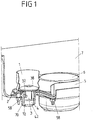
- FIG. 1 shows a perspective view of a section of an airbag module for a motor vehicle, which comprises a arranged in a module housing 7, to protect a vehicle occupant inflatable airbag 2 and arranged on the module housing 7 gas generator 6 for inflating the airbag 2.
- a gas bag holder 5 here in the form of a holding plate, provided which is secured by suitable fasteners 58, here in the form of screws and associated nuts on the module housing 7, more precisely at the bottom, wherein the Airbag 2 is clamped for example between the airbag holder 5 and the module housing 7.
- the gas bag 2 of such an airbag module can, usually sensor-controlled, be filled with gas by means of the gas generator 6, so that it exits the module housing 7 and in unfolded, inflated state a gas cushion to protect a vehicle occupant (or possibly also one outside the motor vehicle person).
- the outlet cross-section of the vent opening is changeable, z. B., in which the inflatable element in a defined manner cooperates with a vent opening associated cover member or even forms such a cover.
- the vent opening can be provided on the gas bag itself.
- the main focus is on the arrangement and fixation of the inflatable element 1 and the associated trip unit 4 on or in the airbag module, which will be described below with reference to FIGS FIG. 1 as well as the detailed representations according to FIG. 2 and 3 will be explained.
- FIG. 2 shows a section of the airbag module FIG. 1 in the region of the trip unit 4 and an associated fastener 3, wherein for better visibility of individual details of the airbag 2 and the inflatable element 1 are not shown.
- FIG. 3 shows a part of the module housing 7 FIG. 1 , Specifically, a section of the bottom portion of that housing to which the gas bag 2 and the gas generator 6 and the inflatable element 1 and the trip unit 4 are arranged.
- the trip unit 4 is disposed within the module housing 7, so that it is surrounded by walls of the module housing 7. Specifically, the trip unit 4 is located in an extension 70 of the module housing, which protrudes from the main chamber of the module housing 7, in which the (folded) airbag 2 is arranged and into which the gas generator 6 serving for inflating the airbag 2 projects.
- the extension 70 of the module housing 7 is (axially) elongated and has an annular, in particular annular, cross-section, so that the release unit 4 can be inserted axially into the extension 70. It is integrally formed in the embodiment of the wall of the main chamber of the module housing 7, more precisely at the bottom thereof.
- One another radially (flat) stops 41, 71 of the trip unit 4 and the extension 70 cause a (radial) securing position of the trip unit. 4
- a captive fixation of the trip unit 4 in the module housing 7 or in the exemplary embodiment more precisely in the extension 70 is achieved by a fastener 3.
- the gas bag holder 5 resting on the bottom of the module housing, formed by a holding plate in the exemplary embodiment, has a Opening on whose edge 52 is engaged behind by latching hooks 32 of the fastening element 3; it may be present in particular a locking connection.
- the fastener 3 is locked in a position in which it holds the trip unit 4 in the extension 70 of the module housing 7.
- at least one stop 34 is provided on the fastener 3, which cooperates with an associated stop 44 of the trip unit 4 and axially opposite the first stop pair 42, 72 of trip unit 4 and extension 70 opposite.
- the tripping unit 4 is fixed axially in the extension 70 of the module housing 7 via the two stop pairs 34, 44 and 42, 72. And perpendicular thereto (in the radial direction) it is held by the annular circumferential wall of the extension 70 and by the projecting into the extension 70 main body 30 of the fastener 3.
- the trip unit 4 also has the tendency to expand when the associated gas source is triggered (in the radial direction R), as a result of which the latching hooks 32 are pressed outwards and the latching action is even more intensified.
- FIG. 2 Furthermore, a gap Z1 between the module housing 7, more precisely its bottom, on the one hand and the gas bag holder 5 attached thereto on the other hand indicated.
- This gap Z1 results from the fact that in FIG. 2 the gas bag to be arranged in the module housing 7 is not shown.
- the intermediate space Z1 of the airbag 2 is clamped in accordance with the intended arrangement in the module housing 7 in a conventional manner in the region of its injection opening between the housing bottom and the gas bag holder 5.
- the triggering unit 4 counteracts an unlocking of the fastening element 3, more precisely the hook 32 of the fastening element 3. Because for an unlocking of the fastener 3, the edge 52 of the airbag retainer engaging behind latching hooks 32 would have to be compressed or pressed inward, but this is prevented by the trip unit 4, the outer wall forms a compression of the latching hooks 32 counteracting stop surface.
- the fastener 3 also has a head 38 which engages over the edge 52 of the opening in the gas bag holder 5.
- a pressure hose inflatable element 1 in the region of its inlet opening form-fitting and / or clamping can be fixed.
- the fastening element 3 defines a passage 36 in the region of the head 38 through which gas released by the triggering unit 4 can pass into the inflatable element 1.
- a single fastener 3 serves both for fixing the trip unit 4 in the module housing 7 or more precisely in an extension 70 of the module housing 7 and for fixing the inflatable element 1 on the module housing, in such a way that it runs inside the airbag 2.
- FIG. 3 can thereby recognize additional details of the bottom of the module housing 7, on which the extension 70 is formed and on which the gas bag holder 5 is applied, compare FIGS. 1 and 2 ,
- the bottom of the module housing 7 has a plurality of fastening openings 76, through which the module housing 7 can be connected to the gas bag holder 5, as in FIGS FIGS. 1 and 2 shown.
- a large-area cutout 75 is provided, through which the gas generator 6 protrudes into the main chamber of the module housing 7, as also in FIG FIG. 1 shown.
- the inflatable element 1 arranged within the airbag 2 according to the exemplary embodiment may alternatively also be provided outside the airbag 2, as in FIG FIG. 2 indicated by dashed lines.
Landscapes
- Engineering & Computer Science (AREA)
- Mechanical Engineering (AREA)
- Physics & Mathematics (AREA)
- Fluid Mechanics (AREA)
- Air Bags (AREA)
Description
- Die Erfindung betrifft ein Airbagmodul für ein Kraftfahrzeug nach dem Oberbegriff des Anspruchs 1.
- Ein derartiges Airbagmodul umfasst einen Gassack, der zum Schutz einer Person, insbesondere eines Fahrzeuginsassen, mittels eines Gasgenerators aufblasbar ist, sowie ein Modulgehäuse zur Aufnahme des Gassackes und eine Gassackhalterung zur Festlegung des Gassackes am Modulgehäuse, welche üblicherweise mit letzterem verbunden ist, z. B. über mindestens eine Schraube.
- Das Airbagmodul weist regelmäßig weiterhin eine Entlüftungsöffnung auf, durch die hindurch aus dem Airbagmodul stammendes Gas, welches vom Gasgenerator zum Aufblasen des Gassackes freigesetzt wurde, aus dem Airbagmodul entweichen kann, wobei zur Regulierung des Gasdrucks im Gassack der Austrittsquerschnitt der Entlüftungsöffnung steuerbar ist. Hierzu ist ein (von dem Gassack verschiedenes) aufblasbares Element vorgesehen, das an der Gassackhalterung festgelegt ist und das im aufgeblasenen Zustand mit einer Entlüftungsöffnung des Airbagmodules zusammenwirkt, um deren Austrittsquerschnitt zu steuern, also insbesondere verändern zu können.
- Dem aufblasbaren Element ist eine (von dem zum Aufblasen des Gassackes dienenden Gasgenerator verschiedene) Auslöseeinheit zugeordnet, über die das aufblasbare Element, z.B. sensorgesteuert, mit Gas befüllbar ist, um eine gewünschte Steuerung bzw. Veränderung des Austrittsquerschnitts der zugeordneten Entlüftungsöffnung des Airbagmodules herbeizuführen.
- Mit einer derartigen Vorrichtung ist es möglich, das sogenannte Entlüften eines Gassackes, d. h., das Ablassen derjenigen Gase, welche zum Schutz eines Fahrzeuginsassen von einem Gasgenerator freigesetzt und in den Gassack eingebracht wurden, gezielt zu steuern, etwa in Abhängigkeit von der Art und Schwere eines Unfalls sowie von der Größe und/oder dem Gewicht und/oder der Sitzposition einer zu schützenden Person, was insbesondere mittels Sensoren erfasst werden kann.
- Zum gezielten Befüllen des aufblasbaren Elementes mit einem Gas, um die gewünschte Regulierung des Gasdruckes im Gassack bzw. eine gewünschte Steuerung des Austrittsquerschnittes der zugehörigen Entlüftungsöffnung herbei zu führen, umfasst die Auslöseeinheit einer Gasquelle, welche beispielsweise pyrotechnisch gezündet werden kann und sodann ein Gas freisetzt, mit dem das aufblasbare Element befüllt wird, so dass es mit der besagten Belüftungsöffnung zusammenwirkt und deren Austrittsquerschnitt steuert (ändert).
- Dabei kann gemäß einer Variante die Entlüftungsöffnung ursprünglich von einem Abdeckteil überdeckt sein, so dass die Steuerung des Austrittsquerschnitts mittels des aufblasbaren Elementes in der Weise erfolgt, dass das aufblasbare Element eine zumindest teilweise Freigabe der Entlüftungsöffnung bewirkt, z.B. durch entsprechende Einwirkung auf das Abdeckteil. Nach einer anderen Variante kann die Entlüftungsöffnung ursprünglich frei liegen und erst beim Befüllen des aufblasbaren Elementes mit Gas zumindest teilweise überdeckt werden. Auch ist es möglich, dass die Entlüftungsöffnung anfänglich durch ein Abdeckteil teilweise überdeckt ist und durch Einwirkung des aufblasbaren Elementes der Überdeckungsgrad geändert wird.
- Ein Airbagmodul mit einem derartigen Mechanismus zur Regulierung des Gasdruckes im Gassack ist aus der
WO 2011/157 631 A1 bekannt. Auf diese Druckschrift wird vorliegend insbesondere hinsichtlich des Befüllens des aufblasbaren Elementes mit einem Gas sowie hinsichtlich des Zusammenwirkens des aufblasbaren Elementes mit einer Entlüftungsöffnung des Airbagmodules vollumfänglich Bezug genommen. - Gemäß der
WO 2011/157 631 A1 ist die dem aufblasbaren Element zugeordnete Auslöseeinheit unterhalb des Bodens des Modulgehäuses angeordnet und im Gehäuseboden ein Durchlass ausgebildet, durch den hindurch die von der Auslöseeinheit freigesetzten Gase in das hiermit zu befüllende aufblasbare Element eingeleitet werden können. - Der Erfindung liegt das Problem zugrunde, ein Airbagmodul der eingangs genannten Art weiter zu verbessern.
- Dieses Problem wird erfindungsgemäß durch die Schaffung eines Airbagmodules mit den Merkmalen des Anspruchs 1 gelöst.
- Danach ist die Auslöseeinheit innerhalb des Modulgehäuses in einem Fortsatz des Modulgehäuses, der von einer den Gassack aufnehmenden Hauptkammer des Modulgehäuses absteht, angeordnet ist. Die Auslöseeinheit lässt sich dabei in einfacher Weise mittels eines, z.B. aus Kunststoff bestehenden, Befestigungselementes, insbesondere mittels genau eines einzelnen Befestigungselementes, im Modulgehäuse bzw. genauer in dessen Fortsatz fixieren. Hierzu kann die Auslöseeinheit formschlüssig mit dem Befestigungselement in Verbindung stehen, insbesondere in der Weise, dass sich die Auslöseeinheit an ihrer Außenseite am Befestigungselement abstützt, gegebenenfalls auch über die gesamte Ausdehnung der Außenseite. So greift das Befestigungselement in den Fortsatz ein und umfasst dort die Auslöseeinheit zumindest abschnittsweise.
- Hierdurch wird einerseits die Auslöseeinheit vor Umwelteinflüssen geschützt und andererseits ist auch die Umgebung des Airbagmoduls vor Einwirkungen der Auslöseeinheit beim Zünden der zugehörigen Gasquelle geschützt.
- Der erfindungsgemäßen Lösung scheint die Schwierigkeit entgegenzustehen, dass das Modulgehäuse durch den in einem zusammengestauchten bzw. gefalteten Zustand hierin untergebrachten Gassack belegt ist und daher im Modulgehäuse kein Raum für die Anordnung der dem aufblasbaren Element zugeordneten Auslöseeinheit zur Verfügung steht.
- Es wurde jedoch erkannt, dass vorliegend eine Anordnung der Auslöseeinheit in einem Fortsatz des Modulgehäuses technisch möglich und vorteilhaft ist, der von der den gefalteten Gassack aufnehmenden Kammer ("Hauptkammer") des Modulgehäuses absteht und einstückig mit dieser geformt ist. Hierdurch kann erreicht werden, dass die Auslöseeinheit einerseits in einem von den Wänden des Modulgehäuses begrenzten (und geschützten) Raum aufgenommen ist, gleichzeitig aber separat von dem im Modulgehäuse vorgesehenen Gassack untergebracht werden kann.
- Gemäß einer Ausführungsform ist jener Fortsatz längs (axial) erstreckt und im Querschnitt ringförmig, insbesondere kreisringförmig umlaufend ausgeführt.
- Konkret kann die Auslöseeinheit zwischen dem Befestigungselement und einem Anschlag des Modulgehäuses, insbesondere einem Anschlag an einem zur Aufnahme der Auslöseeinheit vorgesehenen Fortsatz des Modulgehäuses, gehalten sein.
- Ferner kann das Befestigungselement (z. B. in Form eines Befestigungsclips) mindestens einen Rasthaken aufweisen, der an dem Modulgehäuse und/oder der Gassackhalterung verrastbar ist, um die Fixierung der Auslöseeinheit am Modulgehäuse zu erreichen; also entweder eine direkte Fixierung oder eine indirekte Fixierung über die mit dem Modulgehäuse verbundene Gassackhalterung.
- Die Anordnung kann dabei derart ausgeführt sein, dass der mindestens eine Rasthaken des Befestigungselementes im verrasteten Zustand durch die Auslöseeinheit an einer Entrastung gehindert wird, z. B. indem der Rasthaken mit der Auslöseeinheit in Kontakt gerät, wenn er derart verformt wird, dass er mit der Gassackhalterung außer Eingriff geraten könnte und hierdurch eine weitere Verformung des Rasthakens verhindert wird.
- Bei einem Auslösen der der Auslöseeinheit zugeordneten Gasquelle und einem hiermit verbundenen (radialen) Ausdehnen der Auslöseeinheit können zudem die Rasthaken des Befestigungselementes tendenziell noch derart weggedrückt werden, dass hierdurch die Verbindung zwischen Befestigungselement bzw. Rasthaken einerseits und Gassackhalterung andererseits sogar noch verstärkt wird.
- Das mittels der Auslöseeinheit mit Gas befüllbare aufblasbare Element, welches z. B. als ein aufblasbarer Schlauch ("Druckschlauch") ausgeführt sein kann, ist vorteilhaft innerhalb des zugeordneten Gassackes angeordnet; es kann jedoch auch außerhalb des Gassackes liegen.
- Das zur Fixierung der Auslöseeinheit im Modulgehäuse dienende Befestigungselement kann dabei weiterhin auch zur Festlegung des aufblasbaren Elementes dienen, z. B. indem der mindestens eine Rasthaken und/oder ein Kopf des Befestigungselementes zur Fixierung des aufblasbaren Elementes an der Gassackhalterung vorgesehen ist.
- Die Anordnung und Befestigung einerseits der Auslöseeinheit innerhalb des Modulgehäuses und andererseits des aufblasbaren Elementes innerhalb des Gassackes kann dann mittels der Gassackhalterung und des Befestigungselementes in einem Arbeitsgang erfolgen.
- Weitere Einzelheiten und Vorteile der Erfindung werden bei der nachfolgenden Beschreibung eines Ausführungsbeispieles anhand der Figuren deutlich werden.
- Es zeigen:
- Fig. 1
- einen Ausschnitt eines Airbagmodules, das einen Gassack, einen Gasgenerator zum Aufblasen des Gassackes sowie ein Modulgehäuse zur Aufnahme des Gassackes umfasst;
- Fig. 2
- ein Detail des Airbagmodules aus
Figur 1 im Bereich eines Befestigungselementes, über das ein zur Regulierung des Innendruckes des Gassackes vorgesehenes aufblasbares Element sowie eine zugehörige Auslöseeinheit am Airbagmodul festgelegt sind; - Fig. 3
- einen Ausschnitt des Bodenbereiches des Modulgehäuses aus
Figur 1 . -
Figur 1 zeigt in einer perspektivischen Darstellung einen Ausschnitt eines Airbagmodules für ein Kraftfahrzeug, das einen in einem Modulgehäuse 7 angeordneten, zum Schutz eines Fahrzeuginsassen aufblasbaren Gassack 2 sowie einen am Modulgehäuse 7 angeordneten Gasgenerator 6 zum Aufblasen des Gassackes 2 umfasst. Zur Festlegung des Gassackes 2 am Modulgehäuse 7 ist dabei eine Gassackhalterung 5, hier in Form eines Haltebleches, vorgesehen, welche durch geeignete Befestigungsmittel 58, hier in Form von Schrauben und zugeordneten Muttern, am Modulgehäuse 7, genauer an dessen Boden befestigt ist, wobei der Gassack 2 z.B. zwischen der Gassackhalterung 5 und dem Modulgehäuse 7 verklemmt wird. - Der Gassack 2 eines derartigen Airbagmodules kann, in der Regel sensorgesteuert, mittels des Gasgenerators 6 mit Gas befüllt werden, so dass er aus dem Modulgehäuse 7 austritt und im entfalteten, aufgeblasenen Zustand ein Gaskissen zum Schutz eines Fahrzeuginsassen (oder gegebenenfalls auch einer außerhalb des Kraftfahrzeugs befindlichen Person) bildet.
- Je nach Art und Schwere des Unfalls sowie in Abhängigkeit von Gewicht, Größe und Position der zu schützenden Person können dabei unterschiedliche Druckverhältnisse innerhalb des Gassackes 2 vorteilhaft sein. Es ist daher bekannt, vergleiche etwa
WO 2011/157 631 A1 , den Innendruck des Gassackes 2 bei und/oder nach dem Befüllen mit Gas aus dem Gasgenerator 6 gezielt zu steuern. Hierzu dient gemäß derWO 2011/157 631 A1 z. B. ein aufblasbares Element, insbesondere in Form eines Schlauches, dem eine von dem Gasgenerator verschiedene Gasquelle zugeordnet ist und das im mit Gas befüllten Zustand in definierter Weise mit einer Entlüftungsöffnung des Airbagmodules zusammenwirkt, um den Innendruck des Gassackes zu steuern. Dies kann insbesondere in der Weise erfolgen, dass durch das Befüllen des aufblasbaren Elementes mit Gas der Austrittsquerschnitt der Entlüftungsöffnung veränderbar ist, z. B., in dem das aufblasbare Element in definierter Weise mit einem der Entlüftungsöffnung zugeordneten Abdeckteil zusammenwirkt bzw. selbst ein solches Abdeckteil bildet. Die Entlüftungsöffnung kann dabei am Gassack selbst vorgesehen sein. - Für weitere Einzelheiten zum Aufbau und zur Funktion einer solchen Vorrichtung sei auf die
WO 2011/157 631 A1 verwiesen, auf die in dieser Hinsicht vollumfänglich Bezug genommen wird. - Vorliegend geht es im Weiteren vor allem um die Anordnung und Fixierung des aufblasbaren Elementes 1 sowie der zugehörigen Auslöseeinheit 4 am bzw. im Airbagmodul, was nachfolgend anhand der
Figur 1 sowie der Detaildarstellungen gemäßFigur 2 und3 erläutert werden wird. -
Figur 2 zeigt dabei einen Ausschnitt des Airbagmodules ausFigur 1 im Bereich der Auslöseeinheit 4 und eines zugehörigen Befestigungselementes 3, wobei zur besseren Erkennbarkeit einzelner Details der Gassack 2 sowie das aufblasbare Element 1 nicht mit dargestellt sind. UndFigur 3 zeigt einen Teil des Modulgehäuses 7 ausFigur 1 , und zwar konkret einen Ausschnitt des Bodenbereichs jenes Gehäuses, an welchem der Gassack 2 und der Gasgenerator 6 sowie das aufblasbare Element 1 und die Auslöseeinheit 4 angeordnet sind. - Wie in den
Figuren 1 und2 erkennbar, ist die Auslöseeinheit 4 innerhalb des Modulgehäuses 7 angeordnet, so dass sie von Wänden des Modulgehäuses 7 umgeben ist. Konkret befindet sich die Auslöseeinheit 4 in einem Fortsatz 70 des Modulgehäuses, der von der Hauptkammer des Modulgehäuses 7 absteht, in welcher der (gefaltete) Gassack 2 angeordnet ist und in welche der zum Aufblasen des Gassackes 2 dienende Gasgenerator 6 hineinragt. - Der Fortsatz 70 des Modulgehäuses 7 ist (axial) längserstreckt und weist einen ringförmigen, insbesondere kreisringförmigen, Querschnitt auf, so dass die Auslöseeinheit 4 axial in den Fortsatz 70 einführbar ist. Er ist im Ausführungsbeispiel einstückig an der Wandung der Hauptkammer des Modulgehäuses 7, genauer an deren Boden, angeformt.
- Eine definierte (axiale) Positionierung der Auslöseeinheit 4 in dem Fortsatz 70 des Modulgehäuses 7 erfolgt durch einander zugeordnete Anschläge 42, 72 der Auslöseeinheit 4 einerseits und des Fortsatzes 70 andererseits, über welche sich die Auslöseeinheit 4 (axial) an dem Fortsatz 70 des Modulgehäuses 7 abstützt. Einander radial zugewandte (ebene) Anschläge 41, 71 der Auslöseeinheit 4 und des Fortsatzes 70 bewirken eine (radiale) Lagesicherung der Auslöseeinheit 4.
- Eine verliersichere Fixierung der Auslöseeinheit 4 in dem Modulgehäuse 7 bzw. im Ausführungsbeispiel genauer im Fortsatz 70 wird durch ein Befestigungselement 3 erreicht. Dieses ragt in den Fortsatz 70 hinein und greift mit einem (im Querschnitt ringförmigen, hohlen) Grundkörper 30 zwischen die ringförmig umlaufende Wand des Fortsatzes 70 und die Auslöseeinheit 4, derart, dass sich die Auslöseeinheit 4 radial an dem Grundkörper 30 des Befestigungselementes 3 abstützen kann.
- In dem Bereich des Modulgehäuses 7 bzw. genauer des Bodens des Modulgehäuses 7, in welchem der Fortsatz 70 in die den Gassack 2 aufnehmende Hauptkammer des Modulgehäuses 7 übergeht, weist die am Boden des Modulgehäuses anliegende, im Ausführungsbeispiel durch ein Halteblech gebildete, Gassackhalterung 5 eine Öffnung auf, deren Rand 52 von Rasthaken 32 des Befestigungselementes 3 hintergriffen wird; es kann dabei insbesondere eine Rastverbindung vorliegen. Hierdurch ist das Befestigungselement 3 in einer Position verriegelt, in der es die Auslöseeinheit 4 in dem Fortsatz 70 des Modulgehäuses 7 hält. Hierzu ist an dem Befestigungselement 3 mindestens einen Anschlag 34 vorgesehen, der mit einem zugeordneten Anschlag 44 der Auslöseeinheit 4 zusammenwirkt und zwar axial und dem ersten Anschlagspaar 42, 72 von Auslöseeinheit 4 und Fortsatz 70 gegenüberliegend.
- Über die beiden Anschlagspaare 34, 44 und 42, 72 ist daher die Auslöseeinheit 4 axial in dem Fortsatz 70 des Modulgehäuses 7 fixiert. Und senkrecht hierzu (in radialer Richtung) wird sie durch die ringförmig umlaufende Wandung des Fortsatzes 70 sowie durch den in den Fortsatz 70 hineinragenden Grundkörper 30 des Befestigungselementes 3 gehalten.
- Die Auslöseeinheit 4 hat zudem die Tendenz, sich beim Auslösen der zugeordneten Gasquelle (in radialer Richtung R) auszudehnen, wodurch die Rasthaken 32 nach außen gedrückt und die Rastwirkung noch verstärkt wird.
- In
Figur 2 ist weiterhin ein Zwischenraum Z1 zwischen dem Modulgehäuse 7, genauer dessen Boden, einerseits und der daran befestigten Gassackhalterung 5 andererseits angedeutet. Dieser Zwischenraum Z1 resultiert daraus, dass inFigur 2 der im Modulgehäuse 7 anzuordnende Gassack nicht mit dargestellt ist. In dem Zwischenraum Z1 ist der Gassack 2 bei bestimmungsgemäßer Anordnung im Modulgehäuse 7 in üblicher Weise im Bereich seiner Einblasöffnung zwischen dem Gehäuseboden und der Gassackhalterung 5 eingeklemmt. - Anhand einer Zusammenschau der
Figuren 1 und2 wird weiter deutlich, dass die Auslöseeinheit 4 einer Entriegelung des Befestigungselementes 3, genauer der Haken 32 des Befestigungselementes 3 entgegenwirkt. Denn für eine Entriegelung des Befestigungselementes 3 müssten die den Rand 52 der Gassackhalterung hintergreifenden Rasthaken 32 zusammengedrückt bzw. nach innen gedrückt werden, was aber durch die Auslöseeinheit 4 verhindert wird, deren Außenwand einen dem Zusammendrücken der Rasthaken 32 entgegenwirkende Anschlagfläche bildet. - Gemäß den
Figuren 1 und2 weist das Befestigungselement 3 außerdem einen Kopf 38 auf, der den Rand 52 der Öffnung in der Gassackhalterung 5 übergreift. Hierdurch ist in einem zwischen dem Kopf 38 des Befestigungselementes 3 und der Gassackhalterung 5 gebildeten Zwischenraum Z2 das durch einen Druckschlauch gebildete aufblasbare Element 1 im Bereich seiner Einlassöffnung formschlüssig und/oder klemmend festlegbar. - Das Befestigungselement 3 definiert dabei im Bereich des Kopfes 38 einen Durchlass 36, durch den hindurch von der Auslöseeinheit 4 freigesetztes Gas in das aufblasbare Element 1 gelangen kann.
- Im Ergebnis dient also ein einzelnes Befestigungselement 3 sowohl zur Festlegung der Auslöseeinheit 4 im Modulgehäuse 7 bzw. genauer in einem Fortsatz 70 des Modulgehäuses 7 als auch zur Fixierung des aufblasbaren Elementes 1 am Modulgehäuse, und zwar derart, dass dieses innerhalb des Gassackes 2 verläuft.
-
Figur 3 lässt dabei zusätzliche Einzelheiten des Bodens des Modulgehäuses 7 erkennen, an welchem der Fortsatz 70 angeformt ist und an welchem die Gassackhalterung 5 anliegt, vergleicheFiguren 1 und2 . - Danach weist der Boden des Modulgehäuses 7 eine Mehrzahl Befestigungsöffnungen 76 auf, durch die hindurch das Modulgehäuse 7 mit der Gassackhalterung 5 verbindbar ist, wie in den
Figuren 1 und2 dargestellt. - Ferner ist ein großflächiger Ausschnitt 75 vorgesehen, durch den hindurch der Gasgenerator 6 in die Hauptkammer des Modulgehäuses 7 ragt, wie ebenfalls in
Figur 1 gezeigt. - Das gemäß dem Ausführungsbeispiel innerhalb des Gassackes 2 angeordnete aufblasbare Element 1 kann alternativ auch außerhalb des Gassackes 2 vorgesehen sein, wie in
Figur 2 gestrichelt angedeutet.
Claims (15)
- Airbagmodul für ein Kraftfahrzeug, mit- einem Gassack (2), der zum Schutz einer Person mittels eines Gasgenerators (6) aufblasbar ist,- einem Modulgehäuse (7) zur Aufnahme des Gassackes (2), das einen Fortsatz (70) aufweist, der von einer den Gassack (2) aufnehmenden Hauptkammer des Modulgehäuses (7) absteht,- einer Gassackhalterung (5) zur Festlegung des Gassackes am Modulgehäuse (7),- einem aufblasbaren Element (1) zur Regulierung des Gasdrucks im Gassack (2), das an der Gassackhalterung (5) festgelegt ist und das vorgesehen ist, im aufgeblasenen Zustand mit einer Entlüftungsöffnung zusammenzuwirken, durch die hindurch aus dem Airbagmodul stammendes Gas entweichen kann,- einer Auslöseeinheit (4) mit einer Gasquelle zum Befüllen des aufblasbaren Elementes (1) mit Gas, die innerhalb des Modulgehäuses (7) in dem Fortsatz (70) des Modulgehäuses (7) angeordnet ist, wobei die Gasquelle von dem Gasgenerator (6) verschieden ist, und- einem Befestigungselement (3), mittels dem die Auslöseeinheit (4) am Modulgehäuse (7) fixiert ist,dadurch gekennzeichnet,
dass das Befestigungselement (3) mit einem Grundkörper (30), mit dem es die Auslöseeinheit (4) zumindest abschnittsweise umfasst, in den Fortsatz (70) des Modulgehäuses (7) eingreift. - Airbagmodul nach Anspruch 1, dadurch gekennzeichnet, dass die Auslöseeinheit (4) in einem von den Wänden des Modulgehäuses (7) begrenzten Raum angeordnet ist.
- Airbagmodul nach Anspruch 1, dadurch gekennzeichnet, dass der Fortsatz (70) des Modulgehäuses (7) eine im Querschnitt ringförmig umlaufende Begrenzungswand aufweist.
- Airbagmodul nach Anspruch 1, dadurch gekennzeichnet, dass die Auslöseeinheit (4) mittels des Befestigungselementes (3) formschlüssig am Modulgehäuse fixiert ist.
- Airbagmodul nach einem der Ansprüche 1 bis 4, dadurch gekennzeichnet, dass das Befestigungselement (3) mindestens einen Rasthaken (32) aufweist, mit dem es an der Gassackhalterung (5) und/oder dem Modulgehäuse (7) verrastbar ist.
- Airbagmodul nach Anspruch 5, dadurch gekennzeichnet, dass der mindestens eine Rasthaken (32) des Befestigungselementes (3) durch die Auslöseeinheit (4) an einer Entrastung gehindert wird.
- Airbagmodul nach Anspruch 6, dadurch gekennzeichnet, dass der mindestens eine Rasthaken (32) des Befestigungselementes (3) bei einer Deformation, die zu einem Entrasten führen würde, mit einer Anschlagfläche der Auslöseeinheit (4) zur Anlage gerät, so dass einer weiteren Deformation und damit Entriegelung des Rasthakens entgegengewirkt wird.
- Airbagmodul nach einem der vorhergehenden Ansprüche, dadurch gekennzeichnet, dass das Befestigungselement (3) einen Durchlass (36) aufweist, durch den hindurch von der Auslöseeinheit (4) freigesetztes Gas in das aufblasbare Element (1) strömen kann.
- Airbagmodul nach einem der vorhergehenden Ansprüche, dadurch gekennzeichnet, dass die Auslöseeinheit (4) zwischen dem Befestigungselement (3) und einem Anschlag (72) des Modulgehäuses (7) gehalten wird.
- Airbagmodul nach Anspruch 9, dadurch gekennzeichnet, dass der Anschlag (72) am Fortsatz (70) des Modulgehäuses (7) ausgebildet ist.
- Airbagmodul nach einem der vorhergehenden Ansprüche, dadurch gekennzeichnet, dass das aufblasbare Element (1) als ein aufblasbarer Schlauch ausgeführt ist.
- Airbagmodul nach einem der vorhergehenden Ansprüche, dadurch gekennzeichnet, dass das aufblasbare Element (1) innerhalb des Gassackes (2) angeordnet ist.
- Airbagmodul nach einem der vorhergehenden Ansprüche, dadurch gekennzeichnet, dass das Befestigungselement (3) zusätzlich zur Festlegung des aufblasbaren Elementes (1) an der Gassackhalterung (5) dient.
- Airbagmodul nach Anspruch 13, dadurch gekennzeichnet, dass das aufblasbare Element (1) zwischen einem Kopf (38) des Befestigungselementes (3) und der Gassackhalterung (5) verklemmt ist.
- Airbagmodul nach einem der vorhergehenden Ansprüche, dadurch gekennzeichnet, dass der Austrittsquerschnitt der Entlüftungsöffnung durch Befüllen des aufblasbaren Elementes (1) mit Gas vergrößert oder verkleinert wird.
Applications Claiming Priority (2)
| Application Number | Priority Date | Filing Date | Title |
|---|---|---|---|
| DE102013202846.6A DE102013202846A1 (de) | 2013-02-21 | 2013-02-21 | Airbagmodul für ein Kraftfahrzeug |
| PCT/EP2014/053129 WO2014128121A1 (de) | 2013-02-21 | 2014-02-18 | Airbagmodul für ein kraftfahrzeug |
Publications (2)
| Publication Number | Publication Date |
|---|---|
| EP2958776A1 EP2958776A1 (de) | 2015-12-30 |
| EP2958776B1 true EP2958776B1 (de) | 2017-10-18 |
Family
ID=50238355
Family Applications (1)
| Application Number | Title | Priority Date | Filing Date |
|---|---|---|---|
| EP14708498.2A Active EP2958776B1 (de) | 2013-02-21 | 2014-02-18 | Airbagmodul für ein kraftfahrzeug |
Country Status (6)
| Country | Link |
|---|---|
| US (1) | US20150343982A1 (de) |
| EP (1) | EP2958776B1 (de) |
| JP (1) | JP2016508470A (de) |
| CN (1) | CN204801711U (de) |
| DE (1) | DE102013202846A1 (de) |
| WO (1) | WO2014128121A1 (de) |
Cited By (1)
| Publication number | Priority date | Publication date | Assignee | Title |
|---|---|---|---|---|
| US12296779B2 (en) | 2023-04-19 | 2025-05-13 | Joyson Safety Systems Germany Gmbh | Fastening device and airbag module |
Families Citing this family (4)
| Publication number | Priority date | Publication date | Assignee | Title |
|---|---|---|---|---|
| FR3012595B1 (fr) | 2013-10-25 | 2016-07-01 | Autoliv Dev | Allumeur pyrotechnique |
| FR3012394B1 (fr) * | 2013-10-25 | 2017-05-26 | Autoliv Dev | Interface de fixation pour actionneur pyrotechnique |
| DE102017116868A1 (de) * | 2017-07-26 | 2019-01-31 | Trw Airbag Systems Gmbh | Gasgenerator, Gassackmodul und Fahrzeugsicherheitssystem |
| DE102017129392B3 (de) | 2017-12-11 | 2019-04-18 | Takata AG | Gassackmodul für ein Fahrzeuginsassen-Rückhaltesystem eines Kraftfahrzeuges |
Family Cites Families (5)
| Publication number | Priority date | Publication date | Assignee | Title |
|---|---|---|---|---|
| GB2306409B (en) * | 1995-10-23 | 1999-05-26 | Autoliv Dev | Improvements in or relating to an air-bag arrangement |
| DE102005039418B4 (de) | 2005-08-16 | 2012-06-06 | Takata-Petri Ag | Vorrichtung zur Steuerung des Austrittsquerschnitts mindestens einer Entlüftungsöffnung für ein Airbagmodul und Airbagmodul mit einer Vorrichtung zur Steuerung des Austrittsquerschnitts mindestens einer Entlüftungsöffnung |
| DE102006010953A1 (de) * | 2006-03-03 | 2007-09-06 | Takata-Petri Ag | Airbagmodul für ein Kraftfahrzeug |
| DE102010039895A1 (de) | 2010-06-15 | 2011-12-15 | Takata-Petri Ag | Airbagmodul für ein Kraftfahrzeug |
| DE102011015309A1 (de) * | 2011-03-29 | 2012-10-04 | Autoliv Development Ab | Gassackeinheit mit einer Haltevorrichtung für ein Zugelement |
-
2013
- 2013-02-21 DE DE102013202846.6A patent/DE102013202846A1/de not_active Ceased
-
2014
- 2014-02-18 CN CN201490000327.2U patent/CN204801711U/zh not_active Expired - Fee Related
- 2014-02-18 JP JP2015558422A patent/JP2016508470A/ja active Pending
- 2014-02-18 WO PCT/EP2014/053129 patent/WO2014128121A1/de not_active Ceased
- 2014-02-18 US US14/761,535 patent/US20150343982A1/en not_active Abandoned
- 2014-02-18 EP EP14708498.2A patent/EP2958776B1/de active Active
Non-Patent Citations (1)
| Title |
|---|
| None * |
Cited By (1)
| Publication number | Priority date | Publication date | Assignee | Title |
|---|---|---|---|---|
| US12296779B2 (en) | 2023-04-19 | 2025-05-13 | Joyson Safety Systems Germany Gmbh | Fastening device and airbag module |
Also Published As
| Publication number | Publication date |
|---|---|
| CN204801711U (zh) | 2015-11-25 |
| EP2958776A1 (de) | 2015-12-30 |
| WO2014128121A1 (de) | 2014-08-28 |
| US20150343982A1 (en) | 2015-12-03 |
| JP2016508470A (ja) | 2016-03-22 |
| DE102013202846A1 (de) | 2014-08-21 |
Similar Documents
| Publication | Publication Date | Title |
|---|---|---|
| DE69300496T2 (de) | Reaktionsdose mit kreisförmigem Diffusor. | |
| DE102009023961B4 (de) | Aktuator mit Auslösebolzen | |
| DE69316968T2 (de) | Airbagbefestigung in aufblasbaren Rückhaltesystemen | |
| DE69410870T2 (de) | Reaktionsgehäuse eines aufblasbaren Rückhaltesystems | |
| DE102016224858B4 (de) | Curtain-Airbag für ein Fahrzeug | |
| DE102009044734A1 (de) | Seitenairbageinheit für Fahrzeuge | |
| DE10004483A1 (de) | Befestigungsstruktur für Fahrzeuginsassenschutzvorrichtung einschließlich eines aufblasbaren Vorhangs | |
| DE102006044850A1 (de) | Säulenrampenstruktur zur Verhinderung einer Störung bei der Entfaltung eines Vorhangairbags | |
| DE102009049764B4 (de) | Airbaganordnung | |
| DE29706246U1 (de) | Gassack-Modul für ein Fahrzeuginsassen-Rückhaltesystem | |
| EP1769978B1 (de) | Luftsackmodul mit Abströmöffnung | |
| EP2958776A1 (de) | Airbagmodul für ein kraftfahrzeug | |
| EP2006164A2 (de) | Überrollschutzsystem für Kraftfahrzeuge mit zumindest einem pyrotechnisch aufstellbaren Überrollkörper | |
| DE10260385A1 (de) | Sicherheitseinrichtung für ein Fahrzeug, insbesondere ein Kraftfahrzeug | |
| DE102004038459B4 (de) | Airbagmodul zum Schutz eines Kraftfahrzeuginsassen | |
| DE102012105967A1 (de) | Montagevorrichtung für einen Seitenairbag für ein Fahrzeug | |
| EP2176096B1 (de) | Airbagmodul für ein kraftfahrzeug | |
| EP2190699A1 (de) | Brennkammerbaueinheit für ein airbagmodul | |
| DE10039802B4 (de) | Sicherheitseinrichtung für die Insassen eines Fahrzeugs, insbesondere eines Kraftfahrzeugs | |
| WO2012072234A1 (de) | Airbageinrichtung | |
| DE10221659A1 (de) | Airbagmodul mit Druckentlastungsmittel | |
| EP1088711B1 (de) | Beifahrer-Airbagmodul für Kraftfahrzeuge | |
| DE102012220983B4 (de) | Gassackanordnung für ein Fahrzeuginsassen-Rückhaltesystem | |
| DE102018220480A1 (de) | Modulgehäuse für ein Airbagmodul eines Kraftfahrzeugs | |
| EP3613640B1 (de) | Seitengassack für ein fahrzeuginsassen-rückhaltesystem, fahrzeuginsassen-rückhaltesystem sowie fahrzeug |
Legal Events
| Date | Code | Title | Description |
|---|---|---|---|
| PUAI | Public reference made under article 153(3) epc to a published international application that has entered the european phase |
Free format text: ORIGINAL CODE: 0009012 |
|
| 17P | Request for examination filed |
Effective date: 20150319 |
|
| AK | Designated contracting states |
Kind code of ref document: A1 Designated state(s): AL AT BE BG CH CY CZ DE DK EE ES FI FR GB GR HR HU IE IS IT LI LT LU LV MC MK MT NL NO PL PT RO RS SE SI SK SM TR |
|
| AX | Request for extension of the european patent |
Extension state: BA ME |
|
| DAX | Request for extension of the european patent (deleted) | ||
| GRAP | Despatch of communication of intention to grant a patent |
Free format text: ORIGINAL CODE: EPIDOSNIGR1 |
|
| INTG | Intention to grant announced |
Effective date: 20170428 |
|
| GRAS | Grant fee paid |
Free format text: ORIGINAL CODE: EPIDOSNIGR3 |
|
| GRAJ | Information related to disapproval of communication of intention to grant by the applicant or resumption of examination proceedings by the epo deleted |
Free format text: ORIGINAL CODE: EPIDOSDIGR1 |
|
| GRAL | Information related to payment of fee for publishing/printing deleted |
Free format text: ORIGINAL CODE: EPIDOSDIGR3 |
|
| GRAR | Information related to intention to grant a patent recorded |
Free format text: ORIGINAL CODE: EPIDOSNIGR71 |
|
| GRAA | (expected) grant |
Free format text: ORIGINAL CODE: 0009210 |
|
| INTC | Intention to grant announced (deleted) | ||
| AK | Designated contracting states |
Kind code of ref document: B1 Designated state(s): AL AT BE BG CH CY CZ DE DK EE ES FI FR GB GR HR HU IE IS IT LI LT LU LV MC MK MT NL NO PL PT RO RS SE SI SK SM TR |
|
| INTG | Intention to grant announced |
Effective date: 20170911 |
|
| REG | Reference to a national code |
Ref country code: GB Ref legal event code: FG4D Free format text: NOT ENGLISH |
|
| REG | Reference to a national code |
Ref country code: CH Ref legal event code: EP |
|
| REG | Reference to a national code |
Ref country code: AT Ref legal event code: REF Ref document number: 937636 Country of ref document: AT Kind code of ref document: T Effective date: 20171115 Ref country code: IE Ref legal event code: FG4D Free format text: LANGUAGE OF EP DOCUMENT: GERMAN |
|
| REG | Reference to a national code |
Ref country code: DE Ref legal event code: R096 Ref document number: 502014005858 Country of ref document: DE |
|
| REG | Reference to a national code |
Ref country code: NL Ref legal event code: MP Effective date: 20171018 |
|
| REG | Reference to a national code |
Ref country code: LT Ref legal event code: MG4D |
|
| PG25 | Lapsed in a contracting state [announced via postgrant information from national office to epo] |
Ref country code: NL Free format text: LAPSE BECAUSE OF FAILURE TO SUBMIT A TRANSLATION OF THE DESCRIPTION OR TO PAY THE FEE WITHIN THE PRESCRIBED TIME-LIMIT Effective date: 20171018 |
|
| PG25 | Lapsed in a contracting state [announced via postgrant information from national office to epo] |
Ref country code: NO Free format text: LAPSE BECAUSE OF FAILURE TO SUBMIT A TRANSLATION OF THE DESCRIPTION OR TO PAY THE FEE WITHIN THE PRESCRIBED TIME-LIMIT Effective date: 20180118 Ref country code: LT Free format text: LAPSE BECAUSE OF FAILURE TO SUBMIT A TRANSLATION OF THE DESCRIPTION OR TO PAY THE FEE WITHIN THE PRESCRIBED TIME-LIMIT Effective date: 20171018 Ref country code: ES Free format text: LAPSE BECAUSE OF FAILURE TO SUBMIT A TRANSLATION OF THE DESCRIPTION OR TO PAY THE FEE WITHIN THE PRESCRIBED TIME-LIMIT Effective date: 20171018 Ref country code: SE Free format text: LAPSE BECAUSE OF FAILURE TO SUBMIT A TRANSLATION OF THE DESCRIPTION OR TO PAY THE FEE WITHIN THE PRESCRIBED TIME-LIMIT Effective date: 20171018 Ref country code: FI Free format text: LAPSE BECAUSE OF FAILURE TO SUBMIT A TRANSLATION OF THE DESCRIPTION OR TO PAY THE FEE WITHIN THE PRESCRIBED TIME-LIMIT Effective date: 20171018 |
|
| PG25 | Lapsed in a contracting state [announced via postgrant information from national office to epo] |
Ref country code: RS Free format text: LAPSE BECAUSE OF FAILURE TO SUBMIT A TRANSLATION OF THE DESCRIPTION OR TO PAY THE FEE WITHIN THE PRESCRIBED TIME-LIMIT Effective date: 20171018 Ref country code: HR Free format text: LAPSE BECAUSE OF FAILURE TO SUBMIT A TRANSLATION OF THE DESCRIPTION OR TO PAY THE FEE WITHIN THE PRESCRIBED TIME-LIMIT Effective date: 20171018 Ref country code: BG Free format text: LAPSE BECAUSE OF FAILURE TO SUBMIT A TRANSLATION OF THE DESCRIPTION OR TO PAY THE FEE WITHIN THE PRESCRIBED TIME-LIMIT Effective date: 20180118 Ref country code: LV Free format text: LAPSE BECAUSE OF FAILURE TO SUBMIT A TRANSLATION OF THE DESCRIPTION OR TO PAY THE FEE WITHIN THE PRESCRIBED TIME-LIMIT Effective date: 20171018 Ref country code: GR Free format text: LAPSE BECAUSE OF FAILURE TO SUBMIT A TRANSLATION OF THE DESCRIPTION OR TO PAY THE FEE WITHIN THE PRESCRIBED TIME-LIMIT Effective date: 20180119 Ref country code: IS Free format text: LAPSE BECAUSE OF FAILURE TO SUBMIT A TRANSLATION OF THE DESCRIPTION OR TO PAY THE FEE WITHIN THE PRESCRIBED TIME-LIMIT Effective date: 20180218 |
|
| REG | Reference to a national code |
Ref country code: DE Ref legal event code: R097 Ref document number: 502014005858 Country of ref document: DE |
|
| PG25 | Lapsed in a contracting state [announced via postgrant information from national office to epo] |
Ref country code: DK Free format text: LAPSE BECAUSE OF FAILURE TO SUBMIT A TRANSLATION OF THE DESCRIPTION OR TO PAY THE FEE WITHIN THE PRESCRIBED TIME-LIMIT Effective date: 20171018 Ref country code: EE Free format text: LAPSE BECAUSE OF FAILURE TO SUBMIT A TRANSLATION OF THE DESCRIPTION OR TO PAY THE FEE WITHIN THE PRESCRIBED TIME-LIMIT Effective date: 20171018 Ref country code: CZ Free format text: LAPSE BECAUSE OF FAILURE TO SUBMIT A TRANSLATION OF THE DESCRIPTION OR TO PAY THE FEE WITHIN THE PRESCRIBED TIME-LIMIT Effective date: 20171018 Ref country code: SK Free format text: LAPSE BECAUSE OF FAILURE TO SUBMIT A TRANSLATION OF THE DESCRIPTION OR TO PAY THE FEE WITHIN THE PRESCRIBED TIME-LIMIT Effective date: 20171018 |
|
| PLBE | No opposition filed within time limit |
Free format text: ORIGINAL CODE: 0009261 |
|
| STAA | Information on the status of an ep patent application or granted ep patent |
Free format text: STATUS: NO OPPOSITION FILED WITHIN TIME LIMIT |
|
| PG25 | Lapsed in a contracting state [announced via postgrant information from national office to epo] |
Ref country code: SM Free format text: LAPSE BECAUSE OF FAILURE TO SUBMIT A TRANSLATION OF THE DESCRIPTION OR TO PAY THE FEE WITHIN THE PRESCRIBED TIME-LIMIT Effective date: 20171018 Ref country code: IT Free format text: LAPSE BECAUSE OF FAILURE TO SUBMIT A TRANSLATION OF THE DESCRIPTION OR TO PAY THE FEE WITHIN THE PRESCRIBED TIME-LIMIT Effective date: 20171018 Ref country code: RO Free format text: LAPSE BECAUSE OF FAILURE TO SUBMIT A TRANSLATION OF THE DESCRIPTION OR TO PAY THE FEE WITHIN THE PRESCRIBED TIME-LIMIT Effective date: 20171018 Ref country code: PL Free format text: LAPSE BECAUSE OF FAILURE TO SUBMIT A TRANSLATION OF THE DESCRIPTION OR TO PAY THE FEE WITHIN THE PRESCRIBED TIME-LIMIT Effective date: 20171018 |
|
| REG | Reference to a national code |
Ref country code: CH Ref legal event code: PL |
|
| 26N | No opposition filed |
Effective date: 20180719 |
|
| PG25 | Lapsed in a contracting state [announced via postgrant information from national office to epo] |
Ref country code: MC Free format text: LAPSE BECAUSE OF FAILURE TO SUBMIT A TRANSLATION OF THE DESCRIPTION OR TO PAY THE FEE WITHIN THE PRESCRIBED TIME-LIMIT Effective date: 20171018 Ref country code: MT Free format text: LAPSE BECAUSE OF FAILURE TO SUBMIT A TRANSLATION OF THE DESCRIPTION OR TO PAY THE FEE WITHIN THE PRESCRIBED TIME-LIMIT Effective date: 20171018 |
|
| GBPC | Gb: european patent ceased through non-payment of renewal fee |
Effective date: 20180218 |
|
| REG | Reference to a national code |
Ref country code: IE Ref legal event code: MM4A |
|
| REG | Reference to a national code |
Ref country code: BE Ref legal event code: MM Effective date: 20180228 |
|
| PG25 | Lapsed in a contracting state [announced via postgrant information from national office to epo] |
Ref country code: LU Free format text: LAPSE BECAUSE OF NON-PAYMENT OF DUE FEES Effective date: 20180218 Ref country code: LI Free format text: LAPSE BECAUSE OF NON-PAYMENT OF DUE FEES Effective date: 20180228 Ref country code: SI Free format text: LAPSE BECAUSE OF FAILURE TO SUBMIT A TRANSLATION OF THE DESCRIPTION OR TO PAY THE FEE WITHIN THE PRESCRIBED TIME-LIMIT Effective date: 20171018 Ref country code: CH Free format text: LAPSE BECAUSE OF NON-PAYMENT OF DUE FEES Effective date: 20180228 |
|
| REG | Reference to a national code |
Ref country code: FR Ref legal event code: ST Effective date: 20181031 |
|
| PG25 | Lapsed in a contracting state [announced via postgrant information from national office to epo] |
Ref country code: IE Free format text: LAPSE BECAUSE OF NON-PAYMENT OF DUE FEES Effective date: 20180218 |
|
| PG25 | Lapsed in a contracting state [announced via postgrant information from national office to epo] |
Ref country code: FR Free format text: LAPSE BECAUSE OF NON-PAYMENT OF DUE FEES Effective date: 20180228 Ref country code: GB Free format text: LAPSE BECAUSE OF NON-PAYMENT OF DUE FEES Effective date: 20180218 Ref country code: BE Free format text: LAPSE BECAUSE OF NON-PAYMENT OF DUE FEES Effective date: 20180228 |
|
| REG | Reference to a national code |
Ref country code: DE Ref legal event code: R082 Ref document number: 502014005858 Country of ref document: DE Representative=s name: MAIKOWSKI & NINNEMANN PATENTANWAELTE PARTNERSC, DE Ref country code: DE Ref legal event code: R081 Ref document number: 502014005858 Country of ref document: DE Owner name: JOYSON SAFETY SYSTEMS GERMANY GMBH, DE Free format text: FORMER OWNER: TAKATA AG, 63743 ASCHAFFENBURG, DE |
|
| PG25 | Lapsed in a contracting state [announced via postgrant information from national office to epo] |
Ref country code: TR Free format text: LAPSE BECAUSE OF FAILURE TO SUBMIT A TRANSLATION OF THE DESCRIPTION OR TO PAY THE FEE WITHIN THE PRESCRIBED TIME-LIMIT Effective date: 20171018 |
|
| REG | Reference to a national code |
Ref country code: AT Ref legal event code: MM01 Ref document number: 937636 Country of ref document: AT Kind code of ref document: T Effective date: 20190218 |
|
| PG25 | Lapsed in a contracting state [announced via postgrant information from national office to epo] |
Ref country code: AT Free format text: LAPSE BECAUSE OF NON-PAYMENT OF DUE FEES Effective date: 20190218 |
|
| PG25 | Lapsed in a contracting state [announced via postgrant information from national office to epo] |
Ref country code: PT Free format text: LAPSE BECAUSE OF FAILURE TO SUBMIT A TRANSLATION OF THE DESCRIPTION OR TO PAY THE FEE WITHIN THE PRESCRIBED TIME-LIMIT Effective date: 20171018 |
|
| PG25 | Lapsed in a contracting state [announced via postgrant information from national office to epo] |
Ref country code: HU Free format text: LAPSE BECAUSE OF FAILURE TO SUBMIT A TRANSLATION OF THE DESCRIPTION OR TO PAY THE FEE WITHIN THE PRESCRIBED TIME-LIMIT; INVALID AB INITIO Effective date: 20140218 Ref country code: MK Free format text: LAPSE BECAUSE OF NON-PAYMENT OF DUE FEES Effective date: 20171018 Ref country code: CY Free format text: LAPSE BECAUSE OF FAILURE TO SUBMIT A TRANSLATION OF THE DESCRIPTION OR TO PAY THE FEE WITHIN THE PRESCRIBED TIME-LIMIT Effective date: 20171018 |
|
| PG25 | Lapsed in a contracting state [announced via postgrant information from national office to epo] |
Ref country code: AL Free format text: LAPSE BECAUSE OF FAILURE TO SUBMIT A TRANSLATION OF THE DESCRIPTION OR TO PAY THE FEE WITHIN THE PRESCRIBED TIME-LIMIT Effective date: 20171018 |
|
| PGFP | Annual fee paid to national office [announced via postgrant information from national office to epo] |
Ref country code: DE Payment date: 20260220 Year of fee payment: 13 |