EP3613640B1 - Seitengassack für ein fahrzeuginsassen-rückhaltesystem, fahrzeuginsassen-rückhaltesystem sowie fahrzeug - Google Patents
Seitengassack für ein fahrzeuginsassen-rückhaltesystem, fahrzeuginsassen-rückhaltesystem sowie fahrzeug Download PDFInfo
- Publication number
- EP3613640B1 EP3613640B1 EP19191820.0A EP19191820A EP3613640B1 EP 3613640 B1 EP3613640 B1 EP 3613640B1 EP 19191820 A EP19191820 A EP 19191820A EP 3613640 B1 EP3613640 B1 EP 3613640B1
- Authority
- EP
- European Patent Office
- Prior art keywords
- vehicle
- side airbag
- injection
- airbag
- barrier
- Prior art date
- Legal status (The legal status is an assumption and is not a legal conclusion. Google has not performed a legal analysis and makes no representation as to the accuracy of the status listed.)
- Active
Links
Images
Classifications
-
- B—PERFORMING OPERATIONS; TRANSPORTING
- B60—VEHICLES IN GENERAL
- B60R—VEHICLES, VEHICLE FITTINGS, OR VEHICLE PARTS, NOT OTHERWISE PROVIDED FOR
- B60R21/00—Arrangements or fittings on vehicles for protecting or preventing injuries to occupants or pedestrians in case of accidents or other traffic risks
- B60R21/02—Occupant safety arrangements or fittings, e.g. crash pads
- B60R21/16—Inflatable occupant restraints or confinements designed to inflate upon impact or impending impact, e.g. air bags
- B60R21/23—Inflatable members
- B60R21/231—Inflatable members characterised by their shape, construction or spatial configuration
- B60R21/23138—Inflatable members characterised by their shape, construction or spatial configuration specially adapted for side protection
-
- B—PERFORMING OPERATIONS; TRANSPORTING
- B60—VEHICLES IN GENERAL
- B60R—VEHICLES, VEHICLE FITTINGS, OR VEHICLE PARTS, NOT OTHERWISE PROVIDED FOR
- B60R21/00—Arrangements or fittings on vehicles for protecting or preventing injuries to occupants or pedestrians in case of accidents or other traffic risks
- B60R21/02—Occupant safety arrangements or fittings, e.g. crash pads
- B60R21/16—Inflatable occupant restraints or confinements designed to inflate upon impact or impending impact, e.g. air bags
- B60R21/23—Inflatable members
- B60R21/231—Inflatable members characterised by their shape, construction or spatial configuration
- B60R21/232—Curtain-type airbags deploying mainly in a vertical direction from their top edge
-
- B—PERFORMING OPERATIONS; TRANSPORTING
- B60—VEHICLES IN GENERAL
- B60R—VEHICLES, VEHICLE FITTINGS, OR VEHICLE PARTS, NOT OTHERWISE PROVIDED FOR
- B60R21/00—Arrangements or fittings on vehicles for protecting or preventing injuries to occupants or pedestrians in case of accidents or other traffic risks
- B60R21/02—Occupant safety arrangements or fittings, e.g. crash pads
- B60R21/16—Inflatable occupant restraints or confinements designed to inflate upon impact or impending impact, e.g. air bags
- B60R21/23—Inflatable members
- B60R21/231—Inflatable members characterised by their shape, construction or spatial configuration
- B60R21/2334—Expansion control features
- B60R21/2338—Tethers
- B60R2021/23386—External tether means
Definitions
- the invention relates to a side gas bag for a vehicle occupant restraint system, a vehicle occupant restraint system for a vehicle, and a vehicle with a vehicle occupant restraint system.
- Vehicle occupant restraint systems with side gas bags are known, the deployment behavior of the side gas bags being of great importance due to the large window area and the correspondingly small installation space in vehicles.
- Such side airbags are used in particular to protect the head in the event of a side impact and are arranged on the roof frame and / or one of the vehicle pillars - labeled A, B, C or D-pillars from front to back. This distinguishes them from gas bags integrated into the seat or door sill, which are primarily designed for thorax protection.
- a desired deployment behavior is usually achieved in that the side airbag is fastened to the body or body-fixed components of the vehicle via several fastening points.
- the US 2011/0272928 A1 shows such a single-row gas bag with several fastening points and a dividing seam that forms the chamber of the The gas bag is divided into sub-chambers and extends into the chamber from the opposite side to the inflation side.
- a side airbag for a vehicle occupant restraint system of a vehicle which is intended to be attached above the driver's door to the body of the vehicle or to body-mounted components, with an inflation side and an opposite side opposite the inflation side, between which the side airbag is in the inflated state a chamber of the side airbag is provided.
- the side airbag is designed to hold back the occupants of a single row of seats in the vehicle, the side airbag having a barrier which extends into the chamber from the opposite side to the inflation side and which at least partially blocks a gas flow along the opposite side. For example, the barrier completely blocks the flow of gas.
- the invention is based on the knowledge that the deployment behavior of side airbags can best be controlled when the deployment direction runs from the inflation side to the opposite side.
- the barrier now prevents or retards a gas flow along the opposite side, which would result in an unfolding perpendicular to the desired unfolding direction.
- the gas flows predominantly from the inflation side to the opposite side, as a result of which the side airbag also inflates in a controlled manner from the inflation side to the opposite side, ie in the desired direction of deployment.
- the side airbag is in particular a single-row airbag.
- the side airbag has exactly one chamber for restraining vehicle occupants.
- the barrier extends essentially vertically and / or in the middle third of the opposite side from the opposite side in order to achieve a uniform unfolding behavior.
- the side airbag can have at least two side walls which enclose the chamber, wherein the inflation side and / or the opposite side can be at least partially formed by a seam between the side walls.
- the barrier is preferably formed by a seam, in particular a seam between the two side walls, which makes the barrier particularly special can be carried out inexpensively.
- the barrier extends from the seam on the opposite side.
- the barrier and the seam on the opposite side can be designed as one seam.
- the barrier can extend from the opposite side to an end point which is closer to the opposite side than to the inflation side.
- the side airbag has an injection mouth which is provided in the injection side, in particular an imaginary extension of the barrier intersecting one of the ends of the injection mouth. In this way, the development behavior can be set even more precisely.
- the side airbag can have an inflation area which is provided on the side of the inflation mouth facing away from the opposite side and the chamber, wherein the inflation area can be designed for connection to a gas generator.
- the blow-in area and the chamber can be fluidically connected to one another by means of the blow-in mouth.
- the side airbag has exactly one fastening point which is designed for fastening the side airbag to the vehicle, the fastening point being provided on the inflation side, in particular a longitudinal end of the inflation side.
- the side airbag can be fastened securely and inexpensively to the body or to components of the vehicle that are fixed to the body.
- the longitudinal direction corresponds, for example, essentially to the longitudinal direction of the vehicle when the side airbag is intended to be used.
- the fastening point is provided at the front end of the side airbag, ie the end facing the front of the vehicle.
- the blow-in area optionally being able to be designed for fastening to the body.
- the side airbag has a front side and a tether, in particular wherein the tether extends from the front.
- the geometry of the side airbag can be set more precisely in the inflated state.
- the front is defined in relation to the longitudinal direction of the vehicle.
- the object is also achieved by a vehicle occupant restraint system for a vehicle, with a side airbag according to the invention and a gas generator which is connected to the inflation area.
- the object is also achieved by a vehicle with a vehicle occupant restraint system according to the invention, the side airbag being arranged in the area of only one row of seats in the vehicle.
- the side airbag is preferably only connected to the vehicle body or body-mounted components of the vehicle on the inflation side, in particular only by means of the fastening point, and optionally by means of the tether and / or the inflation area, which greatly simplifies the assembly of the vehicle occupant restraint system.
- the tether is attached to the A-pillar.
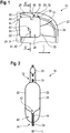
- Figure 1 a portion of a vehicle 10 is shown. More precisely, the area of the driver's door 12 of the vehicle 10 is from the interior of the vehicle 10 can be seen partially. For the sake of clarity, details of the interior, such as the driver's seat, have not been shown.
- the area of the driver's door 12 is equipped with a vehicle occupant restraint system 14, which is shown in the figures in the triggered state.
- the vehicle occupant restraint system 14 comprises at least one side airbag 16 and a gas generator 18, both of which are attached above the driver's door 12 on the body 20 of the vehicle 10 or on components fixed to the body.
- the vehicle occupant restraint system 14 and thus also the side airbag 16 can be designed for the passenger side or for exactly one other row of seats.
- the side airbag 16 is thus a single-row airbag.
- FIG 2 is a sectional view through the side airbag 16 in the inflated state.
- the side airbag 16 has, as in Figure 2 can be seen, two side walls 22 which are connected to one another by means of a seam 24.
- the seam 24 runs around almost the entire circumference of the side airbag 16, so that the two side walls 22 enclose a chamber 26 which holds back the vehicle occupant in the event of an accident.
- the side airbag 16 has only a single chamber 26 for retention.
- the side airbag 16 has an injection area 28 on which the gas generator 18 is provided.
- the blow-in area 28 can also be formed by the two side walls 22 by means of corresponding seams.
- the injection region 28 opens into the chamber 26 at an injection mouth 30 which is provided on one of the sides of the chamber 26.
- the chamber 26 and the blow-in area 28 are thus fluidically connected via the blow-in mouth 30.
- the blow-in area 28 is therefore provided on the side of the blow-in mouth 30 facing away from the chamber 26.
- the side of the side airbag 16 in which the injection mouth 30 is provided is accordingly referred to as the injection side 32.
- the side opposite the inlet side 32 is referred to as the opposite side 34.
- the chamber 26 thus extends between the inlet side 32 and the opposite side 34.
- the inflation side 32 is at the top in the inflated state of the side airbag 16 and the opposite side 34 is at the bottom in the exemplary embodiment shown.
- the inlet side 32 and the opposite side 34 are connected by a front side 35 and a rear side.
- Both the inlet side 32 and the opposite side 34 lie essentially parallel to the longitudinal direction L of the vehicle 10 in the inflated state.
- Both are formed by the seam 24 in the exemplary embodiment shown.
- the front side 35 can also be formed by the seam 24.
- a fastening point 36 is also provided on the inlet side 32, which can be designed as a tab, for example.
- the flap is sewn to the seam 24, for example.
- the fastening point 36 is provided at the front longitudinal end of the inlet side 32, ie it is provided in the longitudinal direction L of the vehicle 10 at the end of the inlet side 32 which is directed towards the front of the vehicle 10.
- the fastening point 36 is fastened to the body 20 of the vehicle 10 or to a component of the vehicle 10 that is fixed to the body.
- the side airbag 16 has a tether 38 which also connects the side airbag 16 to the body 20.
- the tether 38 extends, for example, from the front side 35 and is connected to the body 20, more precisely the A-pillar.
- the limiting strap 38 also extends essentially along the longitudinal axis L in the inflated state of the side airbag 16.
- the side airbag 16 is only connected to the body 20 or body-mounted components of the vehicle 10 via precisely one fastening point 36, apart from the tether 38.
- the side airbag 16 can be connected to the body 20 or components of the vehicle 10 fixed to the body via the blow-in area 28 or the gas generator 18 and / or the tether 38.
- the opposite side 34 is not directly connected to the body 20 or components of the vehicle 10 that are fixed to the body.
- a barrier 40 is provided on the opposite side 34.
- the barrier 40 is provided in the middle of the opposite side 34 and it extends from the opposite side 34 essentially perpendicular to the inlet side 32 and ends at an end point 42.
- the end point 42 is closer to the opposite side 34 than to the inlet side 32, so that the barrier 40 extends over less than half the height of the side airbag 16.
- the barrier 40 is formed by a further seam 44 between the two side walls 22.
- the lock 40 can also be designed differently, for example by an additional component or piece of fabric.
- the barrier 40 is completely closed, so that no gas can flow through the barrier 40.
- the barrier is partially gas-permeable in order to enable a defined gas flow along the opposite side 34.
- the barrier 40 is arranged in such a way that an imaginary extension of the barrier 40 does not intersect the injection mouth.
- the imaginary extension runs between the injection mouth 30 and the gas generator 18.
- the imaginary extension runs on the side of the injection mouth 30 that faces the center of the side airbag 16 in the longitudinal direction.
- the gas generated by the gas generator flows through the injection mouth 30 into the chamber 26 of the side airbag 16, which is not yet inflated at this moment.
- a flow of the gas along the opposite side 34 is at least partially blocked by the lock 40 on the opposite side 34, so that it is ensured that the gas flow predominantly runs from the inlet side 32 to the opposite side 34. In this way it is ensured that the chamber 26 and the side airbag 16 also unfold from the inlet side 32 to the opposite side 34, and this unfolding movement is not disturbed by a transverse flow along the opposite side 34 in the longitudinal direction L.
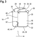
- FIG 3 a second embodiment of the side airbag 16 is shown, which essentially corresponds to that of the first embodiment. In the following, therefore, only the differences will be discussed and parts that are the same and functionally the same are provided with the same reference symbols.
- the injection mouth 30 is not arranged centrally in the injection side 32, but rather adjoins one end of the injection side 32 in the longitudinal direction L, here on the rear end 46.
- the lock 40 is not arranged centrally on the opposite side 34, but is only located in the middle third of the opposite side 34 in the longitudinal direction L.
- the position of the barrier 40 is selected such that an imaginary extension V of the barrier 40 exactly intersects the end 48 of the injection mouth 30 which faces the center of the side airbag 16 or the front side 35.
- the seam 44 of the barrier 40 and the seam 24 of the side walls 22 are also designed as a single, continuous seam in order to save manufacturing costs.
- the side airbag 16 in this embodiment does not have a tether, but is only connected to the body 20 or components of the vehicle 10 fixed to the body via the fastening point 36 and optionally the blow-in area 28 or the gas generator 18.
Landscapes
- Engineering & Computer Science (AREA)
- Mechanical Engineering (AREA)
- Air Bags (AREA)
Description
- Die Erfindung betrifft einen Seitengassack für ein Fahrzeuginsassen-Rückhaltesystem, ein Fahrzeuginsassen-Rückhaltesystem für ein Fahrzeug, sowie ein Fahrzeug mit einem Fahrzeuginsassen-Rückhaltesystem.
- Fahrzeuginsassen-Rückhaltesysteme mit Seitengassäcken sind bekannt, wobei dem Entfaltungsverhalten der Seitengassäcke aufgrund der großen Fensterfläche und dem entsprechend geringen Montageraum in Fahrzeugen eine große Bedeutung zukommt.
- Solche Seitengassäcke dienen insbesondere dem Kopfschutz bei einem Seitenaufprall und sind am Dachrahmen und/oder einer der - von vorne nach hinten mit A, B, C oder D-Säule bezeichneten - Fahrzeugsäulen angeordnet. Damit unterscheiden sie sich von sitz- oder türbrüstungsintegrierten Gassäcken, die vor allem für den Thoraxschutz ausgelegt sind.
- Insbesondere bei kleineren Seitengassäcken, die lediglich für eine einzelne Sitzreihe eines Fahrzeugs vorgesehen sind (Single-Row Gassäcke), ist eine korrekte Entfaltung notwendig, um eine gewünschte Geometrie, die unter Umständen mittels Fangbändern erreicht wird, zu gewährleisten.
- Ein gewünschtes Entfaltungsverhalten wird üblicherweise dadurch erreicht, dass der Seitengassack über mehrere Befestigungsstellen an der Karosserie oder karosseriefesten Bauteilen des Fahrzeugs befestigt ist.
- Solche Befestigungsstellen erhöhen jedoch die Produktions- und Montagekosten des Fahrzeuginsassen-Rückhaltesystems.
- Die
US 2011/0272928 A1 zeigt einen derartigen Single-Row Gassack mit mehreren Befestigungsstellen und einer Unterteilungsnaht, die die Kammer des Gassacks in Teilkammern unterteilt und sich von der Gegenseite zur Einblasseite hin in die Kammer erstreckt. - Es ist daher Aufgabe der Erfindung, einen Seitengassack, ein Fahrzeuginsassen-Rückhaltesystem sowie ein Fahrzeug mit einem Fahrzeuginsassen-Rückhaltesystem bereitzustellen, die geringe Fertigungs- und Montagekoste haben und gleichzeitig ein kontrolliertes Entfaltungsverhalten des Seitengassacks gewährleisten.
- Die Aufgabe wird gelöst durch einen Seitengassack für ein Fahrzeuginsassen-Rückhaltesystem eines Fahrzeugs, der für die Anbringung oberhalb der Fahrertür an der Karosserie des Fahrzeugs oder karosseriefesten Bauteilen vorgesehen ist, mit einer Einblasseite und einer der Einblasseite gegenüberliegenden Gegenseite, zwischen denen im aufgeblasenen Zustand des Seitengassacks eine Kammer des Seitengassacks vorgesehen ist. Der Seitengassack ist dazu ausgelegt, die Insassen einer einzigen Sitzreihe des Fahrzeugs zurückzuhalten, wobei der Seitengassack eine Sperre aufweist, die sich von der Gegenseite zur Einblasseite hin in die Kammer hinein erstreckt und die eine Gasströmung entlang der Gegenseite zumindest teilweise blockiert. Zum Beispiel blockiert die Sperre den Gasstrom vollständig.
- Der Erfindung liegt die Erkenntnis zugrunde, dass das Entfaltungsverhalten von Seitengassäcken am besten kontrolliert werden kann, wenn die Entfaltungsrichtung von der Einblasseite zur Gegenseite verläuft. Durch die Sperre wird nun eine Gasströmung entlang der Gegenseite verhindert bzw. verzögert, die eine Entfaltung senkrecht zur gewünschten Entfaltungsrichtung zur Folge hätte. Im erfindungsgemäßen Seitengassack strömt das Gas also überwiegend von der Einblasseite zur Gegenseite, wodurch sich der Seitengassack ebenfalls von der Einblasseite zur Gegenseite hin kontrolliert aufbläst, also in der gewünschten Entfaltungsrichtung.
- Der Seitengassack ist insbesondere ein Einzelreihenseitengassack (Single-Row Gassack). Beispielsweise hat der Seitengassack genau eine Kammer zum Rückhalten von Fahrzeuginsassen.
- In einer Ausgestaltung der Erfindung erstreckt sich die Sperre im Wesentlichen senkrecht und/oder im mittleren Drittel der Gegenseite von der Gegenseite, um ein gleichmäßiges Entfaltungsverhalten zu erreichen.
- Um den Seitengassack kostengünstig herzustellen, kann der Seitengassack wenigstens zwei Seitenwänden aufweisen, die die Kammer einschließen, wobei die Einblasseite und/oder die Gegenseite zumindest teilweise durch eine Naht zwischen den Seitenwänden gebildet sein kann.
- Vorzugsweise ist die Sperre durch eine Naht gebildet, insbesondere eine Naht zwischen den beiden Seitenwänden, wodurch die Sperre besonders kostengünstig ausgeführt werden kann. Zum Beispiel erstreckt sich die Sperre von der Naht der Gegenseite aus.
- In einer besonders kosteneffektiven Variante können die Sperre und die Naht der Gegenseite als eine Naht ausgeführt sein.
- Um ein schnelles Entfalten des Seitengassacks zu gewährleisten, kann sich die Sperre von der Gegenseite bis zu einem Endpunkt erstrecken, der näher an der Gegenseite als an der Einblasseite liegt.
- In einer Ausführungsform der Erfindung weist der Seitengassack einen Einblasmund auf, der in der Einblasseite vorgesehen ist, insbesondere wobei eine gedachte Verlängerung der Sperre eines der Enden des Einblasmundes schneidet. Auf diese Weise kann das Entfaltungsverhalten noch präziser eingestellt werden.
- Um einen gleichmäßigen Gasstrom in die Kammer zu gewährleisten, kann der Seitengassack einen Einblasbereich aufweisen, der auf der von der Gegenseite und der Kammer abgewandten Seite des Einblasmundes vorgesehen ist, wobei der Einblasbereich zur Verbindung mit einem Gasgenerator ausgebildet sein kann. Dabei können der Einblasbereich und die Kammer mittels des Einblasmundes miteinander fluidisch verbunden sein.
- Erfindungsgemäß weist der Seitengassack genau eine Befestigungsstelle auf, die zur Befestigung des Seitengassacks am Fahrzeug ausgebildet ist, wobei die Befestigungsstelle an der Einblasseite, insbesondere einem Längsende der Einblasseite vorgesehen ist. Auf diese Weise kann der Seitengassack sicher und kostengünstig an der Karosserie oder karosseriefesten Bauteilen des Fahrzeugs befestigt werden.
- Dabei entspricht die Längsrichtung beispielsweise im Wesentlichen der Längsrichtung des Fahrzeugs bei vorgesehener Verwendung des Seitengassack.
- Zum Beispiel ist die Befestigungsstelle am vorderen Ende des Seitengassacks, d.h. dem dem Bug des Fahrzeugs zugewandten Ende vorgesehen. Insbesondere ist nur eine Befestigungsstelle vorgesehen, wobei optional der Einblasbereich zur Befestigung an der Karosserie ausgebildet sein kann.
- In einer Ausführungsform der Erfindung weist der Seitengassack eine Vorderseite und ein Fangband auf, insbesondere wobei sich das Fangband von der Vorderseite erstreckt. Auf diese Weise lässt sich die Geometrie des Seitengassacks im aufgeblasenen Zustand genauer einstellen. Dabei ist die Vorderseite in Bezug zur Längsrichtung des Fahrzeugs definiert.
- Ferner wird die Aufgabe gelöst durch ein Fahrzeuginsassen-Rückhaltesystem für ein Fahrzeug, mit einem erfindungsgemäßen Seitengassack und einem Gasgenerator, der mit dem Einblasbereich verbunden ist.
- Die Aufgabe wird zudem durch ein Fahrzeug mit einem erfindungsgemäßen Fahrzeuginsassen-Rückhaltesystem gelöst, wobei der Seitengassack im Bereich nur einer Sitzreihe des Fahrzeugs angeordnet ist.
- Vorzugsweise ist der Seitengassack nur auf der Einblasseite, insbesondere nur mittels der Befestigungsstelle, und optional mittels des Fangbandes und/oder dem Einblasbereich mit der Karosserie oder karosseriefesten Bauteilen des Fahrzeugs verbunden, wodurch die Montage des Fahrzeuginsassen-Rückhaltesystems stark vereinfacht wird.
- Zum Beispiel ist das Fangband an der A-Säule befestigt.
- Weitere Merkmale und Vorteile der Erfindung ergeben sich aus der nachfolgenden Beschreibung sowie aus den beigefügten Zeichnungen, auf die Bezug genommen wird. In den Zeichnungen zeigen:
-
Figur 1 einen Teil eines erfindungsgemäßen Fahrzeugs mit einem erfindungsgemäßen Fahrzeuginsassen-Rückhaltesystem mit einem erfindungsgemäßen Seitengassack, -
Figur 2 eine Schnittansicht des Seitengassacks nachFigur 1 entlang der Linie II-II, und -
Figur 3 eine zweite Ausführungsform eines erfindungsgemäßen Seitengassacks in Seitenansicht. - In
Figur 1 ist ein Teil eines Fahrzeugs 10 dargestellt. Genauer gesagt ist der Bereich der Fahrertür 12 des Fahrzeugs 10 aus dem Innenraum des Fahrzeugs 10 teilweise zu sehen. Auf die Darstellung von Details des Innenraums, wie dem Fahrersitz, wurde aus Gründen der Übersichtlichkeit verzichtet. - Der Bereich der Fahrertür 12 ist mit einem Fahrzeuginsassen-Rückhaltesystem 14 ausgestattet, das in den Figuren im ausgelösten Zustand dargestellt ist.
- Das Fahrzeuginsassen-Rückhaltesystem 14 umfasst wenigstens einen Seitengassack 16 und einen Gasgenerator 18, die beide oberhalb der Fahrertür 12 an der Karosserie 20 des Fahrzeugs 10 oder karosseriefesten Bauteilen angebracht sind.
- Gut zu erkennen ist, dass das Fahrzeuginsassen-Rückhaltesystem 14 und somit auch der Seitengassack 16 nur für die vordere Sitzreihe des Fahrzeugs 10 ausgelegt sind.
- Selbstverständlich kann das Fahrzeuginsassen-Rückhaltesystem 14 und damit auch der Seitengassack 16 für die Beifahrerseite oder aber auch für genau eine andere Sitzreihe ausgelegt sein.
- Der Seitengassack 16 ist somit ein Einzelreihengassack (Single-Row Gassack).
- In
Figur 2 ist eine Schnittansicht durch den Seitengassack 16 im aufgeblasenen Zustand dargestellt. Der Seitengassack 16 weist, wie inFigur 2 zu erkennen ist, zwei Seitenwände 22 auf, die mittels einer Naht 24 miteinander verbunden sind. - Die Naht 24 umläuft nahezu den gesamten Umfang des Seitengassacks 16, sodass die beiden Seitenwände 22 eine Kammer 26 einschließen, die im Falle eines Unfalls den Fahrzeuginsassen zurückhält.
- Der Seitengassack 16 weist lediglich eine einzige Kammer 26 zur Rückhaltung auf.
- Denkbar ist selbstverständlich auch, dass mehr als zwei Seitenwände zum Einsatz kommen, oder dass die beiden Seitenwände 22 aus einem Stück Stoff hergestellt sind.
- Zudem weist der Seitengassack 16 einen Einblasbereich 28 auf, an dem der Gasgenerator 18 vorgesehen ist. Auch der Einblasbereich 28 kann durch die beiden Seitenwände 22 durch entsprechende Nähte gebildet sein.
- Der Einblasbereich 28 mündet in die Kammer 26 an einem Einblasmund 30, der an einer der Seiten der Kammer 26 vorgesehen ist. Die Kammer 26 und der Einblasbereich 28 sind somit über den Einblasmund 30 fluidisch verbunden. Der Einblasbereich 28 ist also auf der von der Kammer 26 abgewandten Seite des Einblasmundes 30 vorgesehen.
- Die Seite des Seitengassacks 16, in der der Einblasmund 30 vorgesehen ist, wird dementsprechend als Einblasseite 32 bezeichnet.
- Die Seite, die der Einblasseite 32 gegenüberliegt, wird als Gegenseite 34 bezeichnet. Die Kammer 26 erstreckt sich somit zwischen der Einblasseite 32 und der Gegenseite 34.
- Im gezeigten Ausführungsbeispiel befindet sich die Einblasseite 32 im aufgeblasenen Zustand des Seitengassacks 16 oben und die Gegenseite 34 liegt im gezeigten Ausführungsbeispiel unten.
- Die Einblasseite 32 und die Gegenseite 34 sind durch eine Vorderseite 35 und eine Rückseite verbunden.
- Sowohl die Einblasseite 32 als auch die Gegenseite 34 liegen im aufgeblasenen Zustand im Wesentlichen parallel zur Längsrichtung L des Fahrzeugs 10.
- Beide sind im gezeigten Ausführungsbeispiel durch die Naht 24 gebildet. Auch die Vorderseite 35 kann durch die Naht 24 gebildet sein.
- An der Einblasseite 32 ist im gezeigten Ausführungsbeispiel zudem eine Befestigungsstelle 36 vorgesehen, die zum Beispiel als Lasche ausgeführt sein kann. Die Lasche ist beispielsweise mit der Naht 24 vernäht.
- Die Befestigungsstelle 36 ist im gezeigten Ausführungsbeispiel am vorderen Längsende der Einblasseite 32 vorgesehen, d. h. sie ist in Längsrichtung L des Fahrzeugs 10 an dem Ende der Einblasseite 32 vorgesehen, die zum Bug des Fahrzeugs 10 hin gerichtet ist.
- Die Befestigungsstelle 36 ist an der Karosserie 20 des Fahrzeugs 10 oder einem karosseriefesten Bauteil des Fahrzeugs 10 befestigt.
- Außerdem weist der Seitengassack 16 im gezeigten Ausführungsbeispiel ein Fangband 38 auf, das den Seitengassack 16 ebenfalls mit der Karosserie 20 verbindet.
- Das Fangband 38 erstreckt sich beispielsweise von der Vorderseite 35 aus und ist mit der Karosserie 20, genauer gesagt der A-Säule verbunden.
- Auch das Fangband 38 erstreckt sich im Wesentlichen entlang der Längsachse L im aufgeblasenen Zustand des Seitengassacks 16.
- Erfindungsgemäß ist der Seitengassack 16 lediglich über die genau eine Befestigungsstelle 36 mit der Karosserie 20 oder karosseriefesten Bauteilen des Fahrzeugs 10 verbunden, abgesehen von dem Fangband 38.
- Zusätzlich kann der Seitengassack 16 über den Einblasbereich 28 bzw. den Gasgenerator 18 und/oder das Fangband 38 mit der Karosserie 20 oder karosseriefesten Bauteilen des Fahrzeugs 10 verbunden sein.
- Die Gegenseite 34 dagegen ist nicht direkt mit der Karosserie 20 oder karosseriefesten Bauteilen des Fahrzeugs 10 verbunden.
- Um eine gewünschte Gasströmung beim Aufblasen des Seitengassacks 16 zu erreichen, ist an der Gegenseite 34 eine Sperre 40 vorgesehen.
- Die Sperre 40 ist im ersten Ausführungsbeispiel in der Mitte der Gegenseite 34 vorgesehen und sie erstreckt sich von der Gegenseite 34 im Wesentlichen senkrecht zur Einblasseite 32 hin und endet an einem Endpunkt 42.
- Der Endpunkt 42 liegt näher an der Gegenseite 34 als an der Einblasseite 32, sodass sich die Sperre 40 über weniger als die Hälfte der Höhe des Seitengassacks 16 erstreckt.
- Im gezeigten Ausführungsbeispiel ist die Sperre 40 durch eine weitere Naht 44 zwischen den beiden Seitenwänden 22 gebildet. Selbstverständlich kann die Sperre 40 jedoch auch anders ausgestaltet sein, beispielsweise durch ein zusätzliches Bauteil oder Stück Stoff.
- Im gezeigten Ausführungsbeispiel ist die Sperre 40 vollständig geschlossen, sodass kein Gas durch die Sperre 40 strömen kann.
- Denkbar ist selbstverständlich auch, dass die Sperre teilweise gasdurchlässig ist, um eine definierte Gasströmung entlang der Gegenseite 34 zu ermöglichen.
- Im Verhältnis zum Einblasmund 30 ist die Sperre 40 so angeordnet, dass eine gedachte Verlängerung der Sperre 40 den Einblasmund nicht schneidet. Insbesondere verläuft die gedachte Verlängerung zwischen dem Einblasmund 30 und dem Gasgenerator 18. Zum Beispiel verläuft die gedachte Verlängerung auf der Seite des Einblasmundes 30, die der Mitte des Seitengassacks 16 in Längsrichtung zugewandt ist.
- Durch die Sperre 40 wird das Entfaltungsverhalten des Seitengassacks 16 beim Aufblasen, d. h. beim Betätigen des Gasgenerators 18 verbessert.
- Beim Betätigen des Gasgenerators 18 strömt durch den Einblasmund 30 das vom Gasgenerator erzeugte Gas in die Kammer 26 des in diesem Moment noch nicht aufgeblasenen Seitengassacks 16.
- Beim Entfalten und Aufblasen der Kammer 26 entsteht eine Gasströmung innerhalb der Kammer 26 (in
Figur 1 durch Pfeile symbolisiert), die hauptsächlich in Richtung der Gegenseite 34 gerichtet ist. - Durch die Sperre 40 an der Gegenseite 34 wird eine Strömung des Gases entlang der Gegenseite 34 jedoch zumindest teilweise blockiert, sodass gewährleistet ist, dass die Gasströmung überwiegend von der Einblasseite 32 zur Gegenseite 34 verläuft. Auf diese Weise wird sichergestellt, dass die Kammer 26 und der Seitengassack 16 sich ebenfalls von der Einblasseite 32 zur Gegenseite 34 entfalten, und diese Entfaltungsbewegung nicht durch eine Querströmung entlang der Gegenseite 34 in Längsrichtung L gestört wird.
- In
Figur 3 ist eine zweite Ausführungsform des Seitengassacks 16 dargestellt, die im Wesentlichen der der ersten Ausführungsform entspricht. Im Folgenden wird daher lediglich auf die Unterschiede eingegangen und gleiche und funktionsgleiche Teile sind mit denselben Bezugszeichen versehen. - In der zweiten Ausführungsform ist der Einblasmund 30 nicht mittig in der Einblasseite 32 angeordnet, sondern grenzt an ein Ende der Einblasseite 32 in Längsrichtung L an, hier an dem hinteren Ende 46.
- Die Sperre 40 ist in dieser Ausführungsform nicht mittig an der Gegenseite 34 angeordnet, sondern befindet sich lediglich im mittleren Drittel der Gegenseite 34 in Längsrichtung L.
- Außerdem ist die Position der Sperre 40 so gewählt, dass eine gedachte Verlängerung V der Sperre 40 genau das Ende 48 des Einblasmundes 30 schneidet, das der Mitte des Seitengassacks 16 bzw. der Vorderseite 35 zugewandt ist.
- In dieser Ausführungsform ist zudem die Naht 44 der Sperre 40 und die Naht 24 der Seitenwände 22 als eine einzige, durchgehende Naht ausgeführt, um Herstellungskosten zu sparen.
- Außerdem weist der Seitengassack 16 in dieser Ausführungsform kein Fangband auf, sondern ist lediglich über die Befestigungsstelle 36 und optional den Einblasbereich 28 bzw. den Gasgenerator 18 mit der Karosserie 20 oder karosseriefesten Bauteilen des Fahrzeugs 10 verbunden.
Claims (11)
- Seitengassack für ein Fahrzeuginsassen-Rückhaltesystem (14) eines Fahrzeugs (10), der für die Anbringung oberhalb der Fahrertür (12) an der Karosserie (20) des Fahrzeugs (10) oder karosseriefesten Bauteilen vorgesehen ist, mit einer Einblasseite (32) und einer der Einblasseite (32) gegenüberliegenden Gegenseite (34), zwischen denen im aufgeblasenen Zustand des Seitengassacks eine Kammer (26) des Seitengassacks (16) vorgesehen ist,wobei der Seitengassack (16) dazu ausgelegt ist, die Insassen einer einzigen Sitzreihe des Fahrzeugs (10) zurückzuhalten,wobei der Seitengassack (16) eine Sperre (40) aufweist, die sich von der Gegenseite (34) zur Einblasseite (32) hin in die Kammer (26) hinein erstreckt und die eine Gasströmung entlang der Gegenseite (34) zumindest teilweise blockiert,dadurch gekennzeichnet,dass der Seitengassack (16) genau eine Befestigungsstelle (36) aufweist, die zur Befestigung des Seitengassacks (16) am Fahrzeug (10) ausgebildet ist, wobei die Befestigungsstelle (36) an der Einblasseite (32), insbesondere einem Längsende der Einblasseite (32) vorgesehen ist.
- Seitengassack nach Anspruch 1, dadurch gekennzeichnet, dass sich die Sperre (40) im Wesentlichen senkrecht und/oder im mittleren Drittel der Gegenseite (34) von der Gegenseite (34) erstreckt.
- Seitengassack nach Anspruch 1 oder 2, dadurch gekennzeichnet, dass der Seitengassack (16) wenigstens zwei Seitenwänden (22) aufweist, die die Kammer (26) einschließen, wobei die Einblasseite (32) und/oder die Gegenseite (34) zumindest teilweise durch eine Naht (24) zwischen den Seitenwänden (22) gebildet ist.
- Seitengassack nach einem der vorhergehenden Ansprüche, dadurch gekennzeichnet, dass die Sperre (40) durch eine Naht (44) gebildet ist, insbesondere eine Naht (44) zwischen den beiden Seitenwänden (22).
- Seitengassack nach einem der vorhergehenden Ansprüche, dadurch gekennzeichnet, dass sich die Sperre (40) von der Gegenseite (34) bis zu einem Endpunkt erstreckt, der näher an der Gegenseite (34) als an der Einblasseite (32) liegt.
- Seitengassack nach einem der vorhergehenden Ansprüche, dadurch gekennzeichnet, dass der Seitengassack (16) einen Einblasmund (30) aufweist, der in der Einblasseite (32) vorgesehen ist, insbesondere wobei eine gedachte Verlängerung (V) der Sperre (40) eines der Enden (48) des Einblasmundes (30) schneidet.
- Seitengassack nach Anspruch 6, dadurch gekennzeichnet, dass der Seitengassack (16) einen Einblasbereich (28) aufweist, der auf der von der Gegenseite (34) und der Kammer (26) abgewandten Seite des Einblasmundes (30) vorgesehen ist, wobei der Einblasbereich (28) zur Verbindung mit einem Gasgenerator (18) ausgebildet ist.
- Seitengassack nach einem der vorhergehenden Ansprüche, dadurch gekennzeichnet, dass der Seitengassack (16) eine Vorderseite (35) und ein Fangband (38) aufweist, insbesondere wobei sich das Fangband (38) von der Vorderseite (35) erstreckt.
- Fahrzeuginsassen-Rückhaltesystem für ein Fahrzeug (10), mit einem Seitengassack (16) nach einem der vorhergehenden Ansprüche und einem Gasgenerator (18), der mit dem Einblasbereich (28) verbunden ist.
- Fahrzeug mit einem Fahrzeuginsassen-Rückhaltesystem (14) nach Anspruch 9, wobei der Seitengassack (16) im Bereich nur einer Sitzreihe des Fahrzeugs (10) angeordnet ist.
- Fahrzeug nach Anspruch 10, dadurch gekennzeichnet, dass der Seitengassack (16) nur auf der Einblasseite (32), insbesondere nur mittels der Befestigungsstelle (36), und optional mittels des Fangbandes (38) und/oder dem Einblasbereich (28) mit der Karosserie (20) oder karosseriefesten Bauteilen des Fahrzeugs (10) verbunden ist.
Applications Claiming Priority (1)
| Application Number | Priority Date | Filing Date | Title |
|---|---|---|---|
| DE102018120415.9A DE102018120415A1 (de) | 2018-08-21 | 2018-08-21 | Seitengassack für ein fahrzeuginsassen-rückhaltesystem, fahrzeuginsassen-rückhaltesystem sowie fahrzeug |
Publications (2)
| Publication Number | Publication Date |
|---|---|
| EP3613640A1 EP3613640A1 (de) | 2020-02-26 |
| EP3613640B1 true EP3613640B1 (de) | 2021-10-27 |
Family
ID=67658876
Family Applications (1)
| Application Number | Title | Priority Date | Filing Date |
|---|---|---|---|
| EP19191820.0A Active EP3613640B1 (de) | 2018-08-21 | 2019-08-14 | Seitengassack für ein fahrzeuginsassen-rückhaltesystem, fahrzeuginsassen-rückhaltesystem sowie fahrzeug |
Country Status (2)
| Country | Link |
|---|---|
| EP (1) | EP3613640B1 (de) |
| DE (1) | DE102018120415A1 (de) |
Family Cites Families (7)
| Publication number | Priority date | Publication date | Assignee | Title |
|---|---|---|---|---|
| US6575496B2 (en) * | 2001-05-24 | 2003-06-10 | Autoliv Asp, Inc. | System and method and method for seam profile minimization for an inflatable curtain |
| US6991255B2 (en) * | 2002-06-25 | 2006-01-31 | Autoliv Asp, Inc. | Interconnectable inflatable airbag cushion module |
| GB2402111A (en) * | 2003-05-27 | 2004-12-01 | Autoliv Dev | Air bag with two chambers sealed by a strap |
| DE202005011553U1 (de) * | 2004-08-19 | 2005-11-24 | Autoliv Development Ab | Gassack zum Schutz eines Fahrzeuginsassen |
| DE202006010442U1 (de) * | 2005-07-05 | 2006-09-28 | Autoliv Development Ab | Seitenairbageinheit |
| US7556286B2 (en) * | 2005-09-08 | 2009-07-07 | Autoliv Asp, Inc. | Extended inflatable coverage of inflatable curtains |
| US8353530B2 (en) * | 2010-05-07 | 2013-01-15 | Autoliv Asp, Inc. | Inflatable airbag assemblies with anti-slip patches |
-
2018
- 2018-08-21 DE DE102018120415.9A patent/DE102018120415A1/de not_active Withdrawn
-
2019
- 2019-08-14 EP EP19191820.0A patent/EP3613640B1/de active Active
Non-Patent Citations (1)
| Title |
|---|
| None * |
Also Published As
| Publication number | Publication date |
|---|---|
| EP3613640A1 (de) | 2020-02-26 |
| DE102018120415A1 (de) | 2020-02-27 |
Similar Documents
| Publication | Publication Date | Title |
|---|---|---|
| DE4304919B4 (de) | Airbag-Vorrichtung im Bereich eines Dachrahmens eines Fahrzeugs | |
| EP0771698B1 (de) | Gassack-Seitenaufprall-Schutzeinrichtung | |
| DE102011051318B4 (de) | Interne airbag-vorrichtung | |
| DE102016212433B4 (de) | Unidirektionales Ventil für Mehrkammer-Airbags | |
| EP1568544B2 (de) | Seitenaufprall-Rückhaltevorrichtung | |
| DE102011087449B4 (de) | Vorhangairbag für ein Fahrzeug | |
| EP3504089B1 (de) | Airbagvorrichtung für ein kraftfahrzeug, sowie airbagkissen für eine airbagvorrichtung | |
| DE102016224858B4 (de) | Curtain-Airbag für ein Fahrzeug | |
| WO2019166268A1 (de) | Gassackmodul sowie fahrzeuginsassen-rückhaltesystem | |
| DE102007032763A1 (de) | Airbagsystem | |
| DE112017000630B4 (de) | Sicherheits-Airbag | |
| DE102013221983A1 (de) | Vorhangairbag für ein Fahrzeug sowie eine Rückhalteanordnung | |
| DE102017006274B3 (de) | Rückhaltevorrichtung für ein autonom betreibbares Fahrzeug | |
| DE102009019930A1 (de) | Gassackmodul zum Schutz des Thorax- und Kopfbereichs eines Fahrzeuginsassen | |
| WO2019197164A1 (de) | Gassackanordnung für ein fahrzeuginsassen-rückhaltesystem | |
| DE102018202417A1 (de) | Fahrzeuginsassen-Rückhaltesystem | |
| DE102014100550B4 (de) | Produkt, das ein Fahrzeug mit einem Dachrahmen-Airbag umfasst | |
| DE102014004185A1 (de) | Insassenschutzvorrichtung für ein Fahrzeug und Fahrzeug | |
| WO2017103090A1 (de) | Airbagvorrichtung für ein kraftfahrzeug, sowie airbagkissen für eine airbag-vorrichtung | |
| DE102004026313B4 (de) | Überkopf-Airbagsystem | |
| DE102014222658A1 (de) | Seitenvorhang-airbag für fahrzeug mit aufblasbarer erweiterung | |
| EP1745991B1 (de) | Fahrzeuginsassen-Rückhaltesysteme mit einem Gassack | |
| DE20101564U1 (de) | Fahrzeuginsassen-Rückhaltevorrichtung | |
| EP3613640B1 (de) | Seitengassack für ein fahrzeuginsassen-rückhaltesystem, fahrzeuginsassen-rückhaltesystem sowie fahrzeug | |
| DE102020114750A1 (de) | Gassackmodul zur Reduzierung einer schlagartigen Seitwärts- als auch Vorwärtsbewegung eines Insassen |
Legal Events
| Date | Code | Title | Description |
|---|---|---|---|
| PUAI | Public reference made under article 153(3) epc to a published international application that has entered the european phase |
Free format text: ORIGINAL CODE: 0009012 |
|
| STAA | Information on the status of an ep patent application or granted ep patent |
Free format text: STATUS: THE APPLICATION HAS BEEN PUBLISHED |
|
| AK | Designated contracting states |
Kind code of ref document: A1 Designated state(s): AL AT BE BG CH CY CZ DE DK EE ES FI FR GB GR HR HU IE IS IT LI LT LU LV MC MK MT NL NO PL PT RO RS SE SI SK SM TR |
|
| AX | Request for extension of the european patent |
Extension state: BA ME |
|
| RIN1 | Information on inventor provided before grant (corrected) |
Inventor name: SANTIN NAVARRO, PEDRO, JOSE Inventor name: GONZALEZ LOPEZ, CRISTINA |
|
| STAA | Information on the status of an ep patent application or granted ep patent |
Free format text: STATUS: REQUEST FOR EXAMINATION WAS MADE |
|
| 17P | Request for examination filed |
Effective date: 20200826 |
|
| RBV | Designated contracting states (corrected) |
Designated state(s): AL AT BE BG CH CY CZ DE DK EE ES FI FR GB GR HR HU IE IS IT LI LT LU LV MC MK MT NL NO PL PT RO RS SE SI SK SM TR |
|
| STAA | Information on the status of an ep patent application or granted ep patent |
Free format text: STATUS: EXAMINATION IS IN PROGRESS |
|
| 17Q | First examination report despatched |
Effective date: 20201026 |
|
| GRAP | Despatch of communication of intention to grant a patent |
Free format text: ORIGINAL CODE: EPIDOSNIGR1 |
|
| STAA | Information on the status of an ep patent application or granted ep patent |
Free format text: STATUS: GRANT OF PATENT IS INTENDED |
|
| INTG | Intention to grant announced |
Effective date: 20210526 |
|
| RIN1 | Information on inventor provided before grant (corrected) |
Inventor name: GONZALEZ LOPEZ, CRISTINA Inventor name: SANTIN NAVARRO, PEDRO, JOSE |
|
| GRAJ | Information related to disapproval of communication of intention to grant by the applicant or resumption of examination proceedings by the epo deleted |
Free format text: ORIGINAL CODE: EPIDOSDIGR1 |
|
| STAA | Information on the status of an ep patent application or granted ep patent |
Free format text: STATUS: EXAMINATION IS IN PROGRESS |
|
| GRAP | Despatch of communication of intention to grant a patent |
Free format text: ORIGINAL CODE: EPIDOSNIGR1 |
|
| STAA | Information on the status of an ep patent application or granted ep patent |
Free format text: STATUS: GRANT OF PATENT IS INTENDED |
|
| GRAS | Grant fee paid |
Free format text: ORIGINAL CODE: EPIDOSNIGR3 |
|
| INTC | Intention to grant announced (deleted) | ||
| GRAA | (expected) grant |
Free format text: ORIGINAL CODE: 0009210 |
|
| STAA | Information on the status of an ep patent application or granted ep patent |
Free format text: STATUS: THE PATENT HAS BEEN GRANTED |
|
| INTG | Intention to grant announced |
Effective date: 20210910 |
|
| AK | Designated contracting states |
Kind code of ref document: B1 Designated state(s): AL AT BE BG CH CY CZ DE DK EE ES FI FR GB GR HR HU IE IS IT LI LT LU LV MC MK MT NL NO PL PT RO RS SE SI SK SM TR |
|
| REG | Reference to a national code |
Ref country code: GB Ref legal event code: FG4D Free format text: NOT ENGLISH |
|
| REG | Reference to a national code |
Ref country code: CH Ref legal event code: EP |
|
| REG | Reference to a national code |
Ref country code: AT Ref legal event code: REF Ref document number: 1441507 Country of ref document: AT Kind code of ref document: T Effective date: 20211115 |
|
| REG | Reference to a national code |
Ref country code: DE Ref legal event code: R096 Ref document number: 502019002592 Country of ref document: DE |
|
| REG | Reference to a national code |
Ref country code: IE Ref legal event code: FG4D Free format text: LANGUAGE OF EP DOCUMENT: GERMAN |
|
| REG | Reference to a national code |
Ref country code: LT Ref legal event code: MG9D |
|
| REG | Reference to a national code |
Ref country code: NL Ref legal event code: MP Effective date: 20211027 |
|
| PG25 | Lapsed in a contracting state [announced via postgrant information from national office to epo] |
Ref country code: RS Free format text: LAPSE BECAUSE OF FAILURE TO SUBMIT A TRANSLATION OF THE DESCRIPTION OR TO PAY THE FEE WITHIN THE PRESCRIBED TIME-LIMIT Effective date: 20211027 Ref country code: LT Free format text: LAPSE BECAUSE OF FAILURE TO SUBMIT A TRANSLATION OF THE DESCRIPTION OR TO PAY THE FEE WITHIN THE PRESCRIBED TIME-LIMIT Effective date: 20211027 Ref country code: FI Free format text: LAPSE BECAUSE OF FAILURE TO SUBMIT A TRANSLATION OF THE DESCRIPTION OR TO PAY THE FEE WITHIN THE PRESCRIBED TIME-LIMIT Effective date: 20211027 Ref country code: BG Free format text: LAPSE BECAUSE OF FAILURE TO SUBMIT A TRANSLATION OF THE DESCRIPTION OR TO PAY THE FEE WITHIN THE PRESCRIBED TIME-LIMIT Effective date: 20220127 |
|
| PG25 | Lapsed in a contracting state [announced via postgrant information from national office to epo] |
Ref country code: IS Free format text: LAPSE BECAUSE OF FAILURE TO SUBMIT A TRANSLATION OF THE DESCRIPTION OR TO PAY THE FEE WITHIN THE PRESCRIBED TIME-LIMIT Effective date: 20220227 Ref country code: SE Free format text: LAPSE BECAUSE OF FAILURE TO SUBMIT A TRANSLATION OF THE DESCRIPTION OR TO PAY THE FEE WITHIN THE PRESCRIBED TIME-LIMIT Effective date: 20211027 Ref country code: PT Free format text: LAPSE BECAUSE OF FAILURE TO SUBMIT A TRANSLATION OF THE DESCRIPTION OR TO PAY THE FEE WITHIN THE PRESCRIBED TIME-LIMIT Effective date: 20220228 Ref country code: PL Free format text: LAPSE BECAUSE OF FAILURE TO SUBMIT A TRANSLATION OF THE DESCRIPTION OR TO PAY THE FEE WITHIN THE PRESCRIBED TIME-LIMIT Effective date: 20211027 Ref country code: NO Free format text: LAPSE BECAUSE OF FAILURE TO SUBMIT A TRANSLATION OF THE DESCRIPTION OR TO PAY THE FEE WITHIN THE PRESCRIBED TIME-LIMIT Effective date: 20220127 Ref country code: NL Free format text: LAPSE BECAUSE OF FAILURE TO SUBMIT A TRANSLATION OF THE DESCRIPTION OR TO PAY THE FEE WITHIN THE PRESCRIBED TIME-LIMIT Effective date: 20211027 Ref country code: LV Free format text: LAPSE BECAUSE OF FAILURE TO SUBMIT A TRANSLATION OF THE DESCRIPTION OR TO PAY THE FEE WITHIN THE PRESCRIBED TIME-LIMIT Effective date: 20211027 Ref country code: HR Free format text: LAPSE BECAUSE OF FAILURE TO SUBMIT A TRANSLATION OF THE DESCRIPTION OR TO PAY THE FEE WITHIN THE PRESCRIBED TIME-LIMIT Effective date: 20211027 Ref country code: ES Free format text: LAPSE BECAUSE OF FAILURE TO SUBMIT A TRANSLATION OF THE DESCRIPTION OR TO PAY THE FEE WITHIN THE PRESCRIBED TIME-LIMIT Effective date: 20211027 |
|
| REG | Reference to a national code |
Ref country code: DE Ref legal event code: R097 Ref document number: 502019002592 Country of ref document: DE |
|
| PG25 | Lapsed in a contracting state [announced via postgrant information from national office to epo] |
Ref country code: SM Free format text: LAPSE BECAUSE OF FAILURE TO SUBMIT A TRANSLATION OF THE DESCRIPTION OR TO PAY THE FEE WITHIN THE PRESCRIBED TIME-LIMIT Effective date: 20211027 Ref country code: SK Free format text: LAPSE BECAUSE OF FAILURE TO SUBMIT A TRANSLATION OF THE DESCRIPTION OR TO PAY THE FEE WITHIN THE PRESCRIBED TIME-LIMIT Effective date: 20211027 Ref country code: RO Free format text: LAPSE BECAUSE OF FAILURE TO SUBMIT A TRANSLATION OF THE DESCRIPTION OR TO PAY THE FEE WITHIN THE PRESCRIBED TIME-LIMIT Effective date: 20211027 Ref country code: EE Free format text: LAPSE BECAUSE OF FAILURE TO SUBMIT A TRANSLATION OF THE DESCRIPTION OR TO PAY THE FEE WITHIN THE PRESCRIBED TIME-LIMIT Effective date: 20211027 Ref country code: DK Free format text: LAPSE BECAUSE OF FAILURE TO SUBMIT A TRANSLATION OF THE DESCRIPTION OR TO PAY THE FEE WITHIN THE PRESCRIBED TIME-LIMIT Effective date: 20211027 Ref country code: CZ Free format text: LAPSE BECAUSE OF FAILURE TO SUBMIT A TRANSLATION OF THE DESCRIPTION OR TO PAY THE FEE WITHIN THE PRESCRIBED TIME-LIMIT Effective date: 20211027 |
|
| PLBE | No opposition filed within time limit |
Free format text: ORIGINAL CODE: 0009261 |
|
| STAA | Information on the status of an ep patent application or granted ep patent |
Free format text: STATUS: NO OPPOSITION FILED WITHIN TIME LIMIT |
|
| 26N | No opposition filed |
Effective date: 20220728 |
|
| PG25 | Lapsed in a contracting state [announced via postgrant information from national office to epo] |
Ref country code: AL Free format text: LAPSE BECAUSE OF FAILURE TO SUBMIT A TRANSLATION OF THE DESCRIPTION OR TO PAY THE FEE WITHIN THE PRESCRIBED TIME-LIMIT Effective date: 20211027 |
|
| PG25 | Lapsed in a contracting state [announced via postgrant information from national office to epo] |
Ref country code: SI Free format text: LAPSE BECAUSE OF FAILURE TO SUBMIT A TRANSLATION OF THE DESCRIPTION OR TO PAY THE FEE WITHIN THE PRESCRIBED TIME-LIMIT Effective date: 20211027 |
|
| REG | Reference to a national code |
Ref country code: DE Ref legal event code: R082 Ref document number: 502019002592 Country of ref document: DE Representative=s name: MEHNERT, BERNHARD, DE |
|
| PG25 | Lapsed in a contracting state [announced via postgrant information from national office to epo] |
Ref country code: MC Free format text: LAPSE BECAUSE OF FAILURE TO SUBMIT A TRANSLATION OF THE DESCRIPTION OR TO PAY THE FEE WITHIN THE PRESCRIBED TIME-LIMIT Effective date: 20211027 |
|
| REG | Reference to a national code |
Ref country code: CH Ref legal event code: PL |
|
| PG25 | Lapsed in a contracting state [announced via postgrant information from national office to epo] |
Ref country code: LU Free format text: LAPSE BECAUSE OF NON-PAYMENT OF DUE FEES Effective date: 20220814 Ref country code: LI Free format text: LAPSE BECAUSE OF NON-PAYMENT OF DUE FEES Effective date: 20220831 Ref country code: CH Free format text: LAPSE BECAUSE OF NON-PAYMENT OF DUE FEES Effective date: 20220831 |
|
| REG | Reference to a national code |
Ref country code: BE Ref legal event code: MM Effective date: 20220831 |
|
| PG25 | Lapsed in a contracting state [announced via postgrant information from national office to epo] |
Ref country code: IT Free format text: LAPSE BECAUSE OF FAILURE TO SUBMIT A TRANSLATION OF THE DESCRIPTION OR TO PAY THE FEE WITHIN THE PRESCRIBED TIME-LIMIT Effective date: 20211027 |
|
| P01 | Opt-out of the competence of the unified patent court (upc) registered |
Effective date: 20230528 |
|
| PG25 | Lapsed in a contracting state [announced via postgrant information from national office to epo] |
Ref country code: IE Free format text: LAPSE BECAUSE OF NON-PAYMENT OF DUE FEES Effective date: 20220814 |
|
| PG25 | Lapsed in a contracting state [announced via postgrant information from national office to epo] |
Ref country code: BE Free format text: LAPSE BECAUSE OF NON-PAYMENT OF DUE FEES Effective date: 20220831 |
|
| PG25 | Lapsed in a contracting state [announced via postgrant information from national office to epo] |
Ref country code: HU Free format text: LAPSE BECAUSE OF FAILURE TO SUBMIT A TRANSLATION OF THE DESCRIPTION OR TO PAY THE FEE WITHIN THE PRESCRIBED TIME-LIMIT; INVALID AB INITIO Effective date: 20190814 |
|
| GBPC | Gb: european patent ceased through non-payment of renewal fee |
Effective date: 20230814 |
|
| PG25 | Lapsed in a contracting state [announced via postgrant information from national office to epo] |
Ref country code: CY Free format text: LAPSE BECAUSE OF FAILURE TO SUBMIT A TRANSLATION OF THE DESCRIPTION OR TO PAY THE FEE WITHIN THE PRESCRIBED TIME-LIMIT Effective date: 20211027 |
|
| PG25 | Lapsed in a contracting state [announced via postgrant information from national office to epo] |
Ref country code: MK Free format text: LAPSE BECAUSE OF FAILURE TO SUBMIT A TRANSLATION OF THE DESCRIPTION OR TO PAY THE FEE WITHIN THE PRESCRIBED TIME-LIMIT Effective date: 20211027 |
|
| PG25 | Lapsed in a contracting state [announced via postgrant information from national office to epo] |
Ref country code: GB Free format text: LAPSE BECAUSE OF NON-PAYMENT OF DUE FEES Effective date: 20230814 |
|
| PG25 | Lapsed in a contracting state [announced via postgrant information from national office to epo] |
Ref country code: GB Free format text: LAPSE BECAUSE OF NON-PAYMENT OF DUE FEES Effective date: 20230814 |
|
| PG25 | Lapsed in a contracting state [announced via postgrant information from national office to epo] |
Ref country code: MT Free format text: LAPSE BECAUSE OF FAILURE TO SUBMIT A TRANSLATION OF THE DESCRIPTION OR TO PAY THE FEE WITHIN THE PRESCRIBED TIME-LIMIT Effective date: 20211027 |
|
| PG25 | Lapsed in a contracting state [announced via postgrant information from national office to epo] |
Ref country code: GR Free format text: LAPSE BECAUSE OF NON-PAYMENT OF DUE FEES Effective date: 20211027 |
|
| PG25 | Lapsed in a contracting state [announced via postgrant information from national office to epo] |
Ref country code: GR Free format text: LAPSE BECAUSE OF NON-PAYMENT OF DUE FEES Effective date: 20211027 |
|
| PGFP | Annual fee paid to national office [announced via postgrant information from national office to epo] |
Ref country code: FR Payment date: 20250610 Year of fee payment: 7 |
|
| PGFP | Annual fee paid to national office [announced via postgrant information from national office to epo] |
Ref country code: DE Payment date: 20250831 Year of fee payment: 7 |
|
| REG | Reference to a national code |
Ref country code: AT Ref legal event code: MM01 Ref document number: 1441507 Country of ref document: AT Kind code of ref document: T Effective date: 20240814 |
|
| PG25 | Lapsed in a contracting state [announced via postgrant information from national office to epo] |
Ref country code: AT Free format text: LAPSE BECAUSE OF NON-PAYMENT OF DUE FEES Effective date: 20240814 |
|
| PG25 | Lapsed in a contracting state [announced via postgrant information from national office to epo] |
Ref country code: TR Free format text: LAPSE BECAUSE OF FAILURE TO SUBMIT A TRANSLATION OF THE DESCRIPTION OR TO PAY THE FEE WITHIN THE PRESCRIBED TIME-LIMIT Effective date: 20211027 |
|
| PGFP | Annual fee paid to national office [announced via postgrant information from national office to epo] |
Ref country code: AT Payment date: 20260410 Year of fee payment: 5 |