EP2956341B2 - Appareil d'apport d'air comprenant un convertisseur électronique - Google Patents
Appareil d'apport d'air comprenant un convertisseur électronique Download PDFInfo
- Publication number
- EP2956341B2 EP2956341B2 EP14703843.4A EP14703843A EP2956341B2 EP 2956341 B2 EP2956341 B2 EP 2956341B2 EP 14703843 A EP14703843 A EP 14703843A EP 2956341 B2 EP2956341 B2 EP 2956341B2
- Authority
- EP
- European Patent Office
- Prior art keywords
- compressor
- rail vehicle
- electronic converter
- vehicle according
- motor
- Prior art date
- Legal status (The legal status is an assumption and is not a legal conclusion. Google has not performed a legal analysis and makes no representation as to the accuracy of the status listed.)
- Active
Links
- 239000002775 capsule Substances 0.000 claims description 15
- 238000012544 monitoring process Methods 0.000 claims description 6
- 238000011156 evaluation Methods 0.000 claims description 4
- 238000012545 processing Methods 0.000 claims description 3
- 238000012216 screening Methods 0.000 claims 2
- 238000001514 detection method Methods 0.000 description 5
- 239000002184 metal Substances 0.000 description 5
- 238000000034 method Methods 0.000 description 4
- 238000007605 air drying Methods 0.000 description 3
- 238000013461 design Methods 0.000 description 2
- 238000010586 diagram Methods 0.000 description 2
- 230000003213 activating effect Effects 0.000 description 1
- 230000006978 adaptation Effects 0.000 description 1
- 238000004378 air conditioning Methods 0.000 description 1
- 238000004891 communication Methods 0.000 description 1
- 238000001816 cooling Methods 0.000 description 1
- 230000001419 dependent effect Effects 0.000 description 1
- 238000003745 diagnosis Methods 0.000 description 1
- 238000001035 drying Methods 0.000 description 1
- 238000005265 energy consumption Methods 0.000 description 1
- 238000005516 engineering process Methods 0.000 description 1
- 238000009434 installation Methods 0.000 description 1
- 238000012986 modification Methods 0.000 description 1
- 230000004048 modification Effects 0.000 description 1
- 230000008929 regeneration Effects 0.000 description 1
- 238000011069 regeneration method Methods 0.000 description 1
- 238000001179 sorption measurement Methods 0.000 description 1
Images
Classifications
-
- F—MECHANICAL ENGINEERING; LIGHTING; HEATING; WEAPONS; BLASTING
- F04—POSITIVE - DISPLACEMENT MACHINES FOR LIQUIDS; PUMPS FOR LIQUIDS OR ELASTIC FLUIDS
- F04B—POSITIVE-DISPLACEMENT MACHINES FOR LIQUIDS; PUMPS
- F04B49/00—Control, e.g. of pump delivery, or pump pressure of, or safety measures for, machines, pumps, or pumping installations, not otherwise provided for, or of interest apart from, groups F04B1/00 - F04B47/00
- F04B49/06—Control using electricity
-
- B—PERFORMING OPERATIONS; TRANSPORTING
- B60—VEHICLES IN GENERAL
- B60T—VEHICLE BRAKE CONTROL SYSTEMS OR PARTS THEREOF; BRAKE CONTROL SYSTEMS OR PARTS THEREOF, IN GENERAL; ARRANGEMENT OF BRAKING ELEMENTS ON VEHICLES IN GENERAL; PORTABLE DEVICES FOR PREVENTING UNWANTED MOVEMENT OF VEHICLES; VEHICLE MODIFICATIONS TO FACILITATE COOLING OF BRAKES
- B60T17/00—Component parts, details, or accessories of power brake systems not covered by groups B60T8/00, B60T13/00 or B60T15/00, or presenting other characteristic features
- B60T17/002—Air treatment devices
- B60T17/004—Draining and drying devices
-
- B—PERFORMING OPERATIONS; TRANSPORTING
- B60—VEHICLES IN GENERAL
- B60T—VEHICLE BRAKE CONTROL SYSTEMS OR PARTS THEREOF; BRAKE CONTROL SYSTEMS OR PARTS THEREOF, IN GENERAL; ARRANGEMENT OF BRAKING ELEMENTS ON VEHICLES IN GENERAL; PORTABLE DEVICES FOR PREVENTING UNWANTED MOVEMENT OF VEHICLES; VEHICLE MODIFICATIONS TO FACILITATE COOLING OF BRAKES
- B60T17/00—Component parts, details, or accessories of power brake systems not covered by groups B60T8/00, B60T13/00 or B60T15/00, or presenting other characteristic features
- B60T17/02—Arrangements of pumps or compressors, or control devices therefor
-
- B—PERFORMING OPERATIONS; TRANSPORTING
- B60—VEHICLES IN GENERAL
- B60T—VEHICLE BRAKE CONTROL SYSTEMS OR PARTS THEREOF; BRAKE CONTROL SYSTEMS OR PARTS THEREOF, IN GENERAL; ARRANGEMENT OF BRAKING ELEMENTS ON VEHICLES IN GENERAL; PORTABLE DEVICES FOR PREVENTING UNWANTED MOVEMENT OF VEHICLES; VEHICLE MODIFICATIONS TO FACILITATE COOLING OF BRAKES
- B60T17/00—Component parts, details, or accessories of power brake systems not covered by groups B60T8/00, B60T13/00 or B60T15/00, or presenting other characteristic features
- B60T17/18—Safety devices; Monitoring
- B60T17/22—Devices for monitoring or checking brake systems; Signal devices
- B60T17/228—Devices for monitoring or checking brake systems; Signal devices for railway vehicles
-
- F—MECHANICAL ENGINEERING; LIGHTING; HEATING; WEAPONS; BLASTING
- F04—POSITIVE - DISPLACEMENT MACHINES FOR LIQUIDS; PUMPS FOR LIQUIDS OR ELASTIC FLUIDS
- F04B—POSITIVE-DISPLACEMENT MACHINES FOR LIQUIDS; PUMPS
- F04B25/00—Multi-stage pumps
-
- F—MECHANICAL ENGINEERING; LIGHTING; HEATING; WEAPONS; BLASTING
- F04—POSITIVE - DISPLACEMENT MACHINES FOR LIQUIDS; PUMPS FOR LIQUIDS OR ELASTIC FLUIDS
- F04B—POSITIVE-DISPLACEMENT MACHINES FOR LIQUIDS; PUMPS
- F04B35/00—Piston pumps specially adapted for elastic fluids and characterised by the driving means to their working members, or by combination with, or adaptation to, specific driving engines or motors, not otherwise provided for
- F04B35/04—Piston pumps specially adapted for elastic fluids and characterised by the driving means to their working members, or by combination with, or adaptation to, specific driving engines or motors, not otherwise provided for the means being electric
-
- F—MECHANICAL ENGINEERING; LIGHTING; HEATING; WEAPONS; BLASTING
- F04—POSITIVE - DISPLACEMENT MACHINES FOR LIQUIDS; PUMPS FOR LIQUIDS OR ELASTIC FLUIDS
- F04B—POSITIVE-DISPLACEMENT MACHINES FOR LIQUIDS; PUMPS
- F04B49/00—Control, e.g. of pump delivery, or pump pressure of, or safety measures for, machines, pumps, or pumping installations, not otherwise provided for, or of interest apart from, groups F04B1/00 - F04B47/00
- F04B49/06—Control using electricity
- F04B49/065—Control using electricity and making use of computers
-
- F—MECHANICAL ENGINEERING; LIGHTING; HEATING; WEAPONS; BLASTING
- F04—POSITIVE - DISPLACEMENT MACHINES FOR LIQUIDS; PUMPS FOR LIQUIDS OR ELASTIC FLUIDS
- F04C—ROTARY-PISTON, OR OSCILLATING-PISTON, POSITIVE-DISPLACEMENT MACHINES FOR LIQUIDS; ROTARY-PISTON, OR OSCILLATING-PISTON, POSITIVE-DISPLACEMENT PUMPS
- F04C18/00—Rotary-piston pumps specially adapted for elastic fluids
- F04C18/08—Rotary-piston pumps specially adapted for elastic fluids of intermeshing-engagement type, i.e. with engagement of co-operating members similar to that of toothed gearing
- F04C18/12—Rotary-piston pumps specially adapted for elastic fluids of intermeshing-engagement type, i.e. with engagement of co-operating members similar to that of toothed gearing of other than internal-axis type
- F04C18/14—Rotary-piston pumps specially adapted for elastic fluids of intermeshing-engagement type, i.e. with engagement of co-operating members similar to that of toothed gearing of other than internal-axis type with toothed rotary pistons
- F04C18/16—Rotary-piston pumps specially adapted for elastic fluids of intermeshing-engagement type, i.e. with engagement of co-operating members similar to that of toothed gearing of other than internal-axis type with toothed rotary pistons with helical teeth, e.g. chevron-shaped, screw type
-
- F—MECHANICAL ENGINEERING; LIGHTING; HEATING; WEAPONS; BLASTING
- F04—POSITIVE - DISPLACEMENT MACHINES FOR LIQUIDS; PUMPS FOR LIQUIDS OR ELASTIC FLUIDS
- F04C—ROTARY-PISTON, OR OSCILLATING-PISTON, POSITIVE-DISPLACEMENT MACHINES FOR LIQUIDS; ROTARY-PISTON, OR OSCILLATING-PISTON, POSITIVE-DISPLACEMENT PUMPS
- F04C28/00—Control of, monitoring of, or safety arrangements for, pumps or pumping installations specially adapted for elastic fluids
-
- F—MECHANICAL ENGINEERING; LIGHTING; HEATING; WEAPONS; BLASTING
- F04—POSITIVE - DISPLACEMENT MACHINES FOR LIQUIDS; PUMPS FOR LIQUIDS OR ELASTIC FLUIDS
- F04C—ROTARY-PISTON, OR OSCILLATING-PISTON, POSITIVE-DISPLACEMENT MACHINES FOR LIQUIDS; ROTARY-PISTON, OR OSCILLATING-PISTON, POSITIVE-DISPLACEMENT PUMPS
- F04C29/00—Component parts, details or accessories of pumps or pumping installations, not provided for in groups F04C18/00 - F04C28/00
- F04C29/0042—Driving elements, brakes, couplings, transmissions specially adapted for pumps
- F04C29/0085—Prime movers
Definitions
- the present invention relates to an air supply system comprising a compressor driven by a motor to generate compressed air, an air dryer system for dehumidifying the compressed air generated, an electronic converter for demand-dependent compressor control and several analog and / or digital sensors for generating electrical signals.
- the field of application of the invention extends to rail vehicles whose compressed air supply system is primarily used to provide brake pressure for the vehicle brakes.
- auxiliary converters For example, compressor drives for air supply systems in rail vehicles are fed by so-called auxiliary converters.
- An input converter takes care of the adaptation of the input voltage and a large number of output converters adapt to the various consumers.
- the auxiliary converter not only serves the air supply system, but also other devices such as device fans and air conditioning systems.
- A1 shows a compressor device of a rail vehicle, the control device being connectable to the compressor device.
- a first detection means is provided for detecting available regenerated braking energy.
- a control means is provided for activating the compressor device as a function of the braking energy detected by the first detection means.
- the control means is configured in such a way that it activates the compressor device as soon as the first detection means detects a predefinable quantity of available braking energy.
- a second detection means is provided for detecting the pressure in a compressed air line system of the rail vehicle. The task of the control device is to achieve a reduction in energy consumption for a compressor device of a rail vehicle.
- the DE 10 2010 020 266 A1 discloses a compressed air supply system with a compressor for generating compressed air, an air dryer system for dehumidifying the compressed air generated and sensors for generating electrical signals.
- the system is switched between load, regeneration and relief phases by a brake control device that contains two mutually monitoring microprocessors.
- the electrical signals can be used to control the electronic converter and to monitor and control the compressor, the electrical signals generated by the sensors being processed in the electronic converter into bus signals which can be provided for evaluation at a bus interface.
- the electronic converter preferably processes the electrical signals into a CAN bus signal. Separate control units for electronic monitoring of the compressor and the motor can be saved.
- the possibility is created to intelligently couple diagnostic signals of the compressor control with other diagnostic and control signals of the converter, to process them further and to establish advantageous operating states through communication between the control devices for the compressor and / or the air supply system.
- the invention includes the technical teaching that the electronic converter is a frequency converter with a programmable controller.
- a user-defined control program is implemented in the electronic converter via the integrated programmable logic controller. This program reads the signals at the analog and digital inputs, processes them and controls them depending on the programming Output frequency.
- the electronic converter preferably has eight analog inputs for processing the sensor signals for monitoring the compressor.
- software comprising control commands for recognizing limit values and generating warning signals is implemented in the programmable logic controller of the electronic converter.
- the advantage of the version with converter is that the computing power of a master (BSG) is relieved, as it only forwards the signals and therefore no calculation is required.
- the compressor is preferably a two-stage oil-free or oil-lubricated piston compressor.
- a single-stage oil-free or oil-lubricated piston compressor is also conceivable.
- the monitoring of the compressor consists of sensors that in particular monitor at least one cylinder wall temperature, one cooling air temperature, one intake temperature and pressures such as a final pressure, an intermediate pressure and a negative pressure on the intake filter.
- oil-lubricated compressors on the other hand, it is also useful to monitor an oil temperature and an air outlet temperature.
- the compressor is a rotary compressor.
- the compressor is preferably a single-stage screw compressor.
- the electronic converter be attached directly to the motor. This enables a compact design to be implemented.
- the motor and the compressor are arranged in a metal capsule, sensor lines arranged between the metal capsule and the electronic converter and thus extending outside the metal capsule having a shield for shielding against electromagnetic interference.
- An electronic converter generates electromagnetic interference due to its design. These can lead to faults in the sensor lines of the diagnostic signals and cause false signals.
- the shielded sensor lines are attached to the metal capsule, preferably by means of a plug.
- the cables are routed unshielded within the metallic capsule, as the capsule itself serves as a shield. Depending on the space available, it is also conceivable to accommodate the converter within the capsule.
- the sensor lines preferably consist of individual strands with shielding. Sensor signals are shielded from the metal capsule and lead to the converter. If a multi-core shielded cable is used, the shield cannot be led to the connector strips in the electronic converter. It has proven to be particularly advantageous to route each individual sensor signal via a cable, preferably through collective screw connections on a housing of the electronic converter.
- the motor is a three-phase motor.
- three-phase motors are smaller in size and therefore have a higher power density.
- three-phase motors work wear-free, since there is no brush wear.
- electric motors produce lower noise emissions during operation.
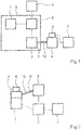
- an air supply system has a compressor 2 operated by an engine 1.
- the compressor 2 is assigned an air dryer system 3 for dehumidifying the compressed air generated.
- the motor 1 is a three-phase motor and the compressor 2 is a single-stage screw compressor.
- the air dryer system 3 works according to the adsorption drying principle.
- various analog and digital sensors 5 are assigned to the compressor 2, which sensors receive various information and feed it to the electronic converter 4 via a sensor line 9.
- the motor 1 as well as the compressor 2 and the sensors 5 are arranged inside a metallic capsule 8.
- the sensor line 9 arranged between sensors 5 and electronic converter 4 has a shield 10 between metallic capsule 8 and electronic converter 4.
- the electrical signals generated by the sensors 5 are used for control purposes of the electronic converter 4 and monitoring of the compressor 2 are used.
- the electrical signals generated by the sensors 5 are processed into bus signals. These bus signals are provided at a bus interface 6 for evaluation.
- a central brake control device 7 the control commands comprehensive software for recognizing limit values and generating warning signals is stored.
- FIG. 2 Another air drying system according to the invention is shown, the electronic converter 4 being attached directly to the motor 1.
- the motor drives the compressor 2 to generate compressed air.
- the air dryer system 3 has the task of dehumidifying the compressed air generated.
- the control commands comprehensive software for the detection of limit values and the generation of warning signals is implemented in the programmable logic controller of the electronic converter 4.
- the electrical connection between sensors 5 and electronic converter 4 takes place via sensor line 9 having shielding 10.
- the invention is not restricted to the preferred exemplary embodiment described above. Rather, modifications thereof are also conceivable, which are also covered by the scope of protection of the following claims.
- the compressor can be a two-stage oil-free or oil-lubricated piston compressor.
Landscapes
- Engineering & Computer Science (AREA)
- Mechanical Engineering (AREA)
- General Engineering & Computer Science (AREA)
- Transportation (AREA)
- Computer Hardware Design (AREA)
- Valves And Accessory Devices For Braking Systems (AREA)
- Control Of Positive-Displacement Pumps (AREA)
- Compressor (AREA)
- Physics & Mathematics (AREA)
- Fuzzy Systems (AREA)
- Mathematical Physics (AREA)
- Software Systems (AREA)
- Theoretical Computer Science (AREA)
- Testing And Monitoring For Control Systems (AREA)
Claims (10)
- Véhicule ferroviaire comportant, pour la mise en œuvre d'une pression de freinage dans des freins de véhicule, un système d'alimentation en air comprimé comportant un compresseur (2) entraîné par un moteur (1) pour produire de l'air comprimé, un système (3) de sécheur d'air pour déshydrater l'air comprimé produit, un convertisseur (4) électronique pour commander le compresseur en fonction des besoins et plusieurs capteurs (5) analogiques et/ou numériques pour produire des signaux électriques,
caractérisé en ce que les signaux électriques peuvent être utilisés pour commander le convertisseur (4) électronique et pour contrôler et commander le compresseur (2) et il s'effectue, dans le convertisseur (4) électronique, une transformation des signaux électriques produits par les capteurs (5) en des signaux de bus, qui peuvent être mis à disposition pour l'exploitation sur une interface (6) de bus. - Véhicule ferroviaire suivant la revendication 1,
caractérisé en ce que le convertisseur (4) électronique est un convertisseur de fréquence ayant une commande à programme enregistré. - Véhicule ferroviaire suivant la revendication 1 ou 2,
caractérisé en ce qu'un logiciel comprenant des instructions de commande est mis en œuvre pour détecter des valeurs limites et pour produire des signaux d'alerte dans la commande à programme enregistré du convertisseur (4) électronique. - Véhicule ferroviaire suivant la revendication 1,
caractérisé en ce que le logiciel, comprenant des instructions de commande pour détecter des valeurs limites et produire des signaux d'alerte, est mémorisé dans un appareil (7) central de commande de frein. - Véhicule ferroviaire suivant la revendication 1,
caractérisé en ce que le compresseur (2) est un compresseur à piston à deux étages, sans huile ou lubrifié à l'huile. - Véhicule ferroviaire suivant la revendication 1,
caractérisé en ce que le compresseur (2) est un compresseur rotatif. - Véhicule ferroviaire suivant la revendication 1,
caractérisé en ce que le convertisseur (4) électronique est fixé directement sur le moteur (1). - Véhicule ferroviaire suivant la revendication 1,
caractérisé en ce que le moteur (1) et le compresseur (2) sont disposés dans une capsule (8) métallique, des lignes (9) de capteur disposées entre la capsule (8) métallique et le convertisseur (4) électronique et s'étendant ainsi à l'extérieur de la capsule (8) métallique, disposant d'un blindage (10) vis-à-vis de parasites électromagnétiques. - Véhicule ferroviaire suivant la revendication 8,
caractérisé en ce que les lignes (9) de capteur sont constituées de torons individuels à blindage. - Véhicule ferroviaire suivant la revendication 1,
caractérisé en ce que le moteur (1) est un moteur à courant triphasé.
Priority Applications (1)
| Application Number | Priority Date | Filing Date | Title |
|---|---|---|---|
| PL14703843T PL2956341T5 (pl) | 2013-02-14 | 2014-02-11 | Instalacja do zasilania w powietrze z przemiennikiem elektronicznym |
Applications Claiming Priority (2)
| Application Number | Priority Date | Filing Date | Title |
|---|---|---|---|
| DE102013101502.6A DE102013101502A1 (de) | 2013-02-14 | 2013-02-14 | Luftversorgungsanlage mit elektronischem Umrichter |
| PCT/EP2014/052599 WO2014124920A1 (fr) | 2013-02-14 | 2014-02-11 | Appareil d'apport d'air comprenant un convertisseur électronique |
Publications (3)
| Publication Number | Publication Date |
|---|---|
| EP2956341A1 EP2956341A1 (fr) | 2015-12-23 |
| EP2956341B1 EP2956341B1 (fr) | 2016-11-30 |
| EP2956341B2 true EP2956341B2 (fr) | 2020-08-12 |
Family
ID=50073188
Family Applications (1)
| Application Number | Title | Priority Date | Filing Date |
|---|---|---|---|
| EP14703843.4A Active EP2956341B2 (fr) | 2013-02-14 | 2014-02-11 | Appareil d'apport d'air comprenant un convertisseur électronique |
Country Status (10)
| Country | Link |
|---|---|
| US (1) | US11300117B2 (fr) |
| EP (1) | EP2956341B2 (fr) |
| JP (1) | JP6448552B2 (fr) |
| KR (1) | KR102157405B1 (fr) |
| CN (1) | CN105008194B (fr) |
| DE (1) | DE102013101502A1 (fr) |
| ES (1) | ES2617703T5 (fr) |
| PL (1) | PL2956341T5 (fr) |
| RU (1) | RU2646961C2 (fr) |
| WO (1) | WO2014124920A1 (fr) |
Families Citing this family (10)
| Publication number | Priority date | Publication date | Assignee | Title |
|---|---|---|---|---|
| DE102015107552A1 (de) | 2015-05-13 | 2016-11-17 | Knorr-Bremse Systeme für Schienenfahrzeuge GmbH | Zentrale Überwachung einer Luftversorgungsanlage für Schienenfahrzeuge |
| DE102016106331A1 (de) | 2016-04-07 | 2017-10-12 | Knorr-Bremse Systeme für Schienenfahrzeuge GmbH | Einrichtung zur Steuerung einer Luftversorgungsanlage eines Fahrzeuges, insbesondere Schienenfahrzeuges |
| DE102016111100A1 (de) | 2016-06-17 | 2017-12-21 | Knorr-Bremse Systeme für Schienenfahrzeuge GmbH | Ventileinrichtung zur Leistungssteigerung mehrstufiger Verdichtereinheiten |
| DE102016111101A1 (de) * | 2016-06-17 | 2017-12-21 | Knorr-Bremse Systeme für Schienenfahrzeuge GmbH | Verfahren und Einrichtung zur Schwingungskompensation bei einem Kolbenkompressor |
| DE102016117327A1 (de) | 2016-09-15 | 2018-03-15 | Knorr-Bremse Systeme für Schienenfahrzeuge GmbH | Hilfsaggregat für eine Lokomotive |
| DE102016011502A1 (de) * | 2016-09-21 | 2018-03-22 | Knorr-Bremse Systeme für Nutzfahrzeuge GmbH | Kompressorsystem für ein Nutzfahrzeug |
| IT201700042515A1 (it) * | 2017-04-18 | 2018-10-18 | D V P Vacuum Tech S P A | Sistema di monitoraggio di una macchina operatrice pneumofora. |
| EP3530530A1 (fr) * | 2018-02-26 | 2019-08-28 | Filkar Otomotiv sanayi ve Ticaret Anonim Sirketi | Système de freinage comportant une unité de commande |
| DE102018215108A1 (de) * | 2018-09-05 | 2020-03-05 | Knorr-Bremse Systeme für Schienenfahrzeuge GmbH | System zur Diagnose und Überwachung von Luftversorgungsanlagen und deren Komponenten |
| DE102019104760A1 (de) * | 2019-02-25 | 2020-08-27 | Knorr-Bremse Systeme für Schienenfahrzeuge GmbH | Luftversorgungsanlage und Verfahren zum Steuern und/oder Überwachen einer Luftversorgungsanlage |
Citations (11)
| Publication number | Priority date | Publication date | Assignee | Title |
|---|---|---|---|---|
| EP0872342A2 (fr) † | 1997-04-17 | 1998-10-21 | MAN Roland Druckmaschinen AG | Système aspiration et/ou soufflage pour une machine d'impression |
| US20060275143A1 (en) † | 2005-05-20 | 2006-12-07 | Copeland Corporation | Sensor for hermetic machine |
| DE102007056318A1 (de) † | 2007-04-12 | 2008-10-16 | Deere & Company, Moline | Kommunikationssystem eines Fahrzeugs und Verfahren zum Betreiben eines Kommunikationssystems |
| US20090254246A1 (en) † | 2008-04-02 | 2009-10-08 | International Truck Intellectual Property Company, Llc | Method and apparatus to optimize energy efficiency of air compressor in vehicle air brake application |
| EP1993893B1 (fr) † | 2006-03-08 | 2010-05-19 | Knorr-Bremse Systeme für Schienenfahrzeuge GmbH | Systeme compresseur |
| EP0976635B2 (fr) † | 1998-07-31 | 2011-01-19 | KNORR-BREMSE Systeme für Nutzfahrzeuge GmbH | Installation d'alimentation en air comprimé pour systèmes à air comprimé de véhicules et procédé d'économie d'énergie dans des installations de préparation d'air comprimé |
| DE102009052510A1 (de) † | 2009-11-11 | 2011-05-12 | Kübrich Ingenieurgesellschaft Mbh & Co. Kg | Kompressor zur Erzeugung von Druckluft |
| DE102010020266A1 (de) † | 2010-05-11 | 2011-11-17 | Knorr-Bremse Systeme für Nutzfahrzeuge GmbH | Vorrichtung zum Steuern einer elektro-pneumatischen Bremseinrichtung |
| EP2388172A1 (fr) † | 2010-05-20 | 2011-11-23 | Siemens Aktiengesellschaft | Module de ramassage électropneumatique pour véhicules ferroviaires |
| CN102588259A (zh) † | 2012-03-01 | 2012-07-18 | 娄卡奔新能源科技发展(上海)有限公司 | 水泥厂空压机组变频恒压控制装置 |
| EP2553537B1 (fr) † | 2010-07-09 | 2015-07-29 | Siemens Aktiengesellschaft | Système de contrôle et de diagnostic pour un système de machine à énergie fluidique et système de machine à énergie fluidique |
Family Cites Families (23)
| Publication number | Priority date | Publication date | Assignee | Title |
|---|---|---|---|---|
| DE3445699A1 (de) * | 1984-12-14 | 1986-06-19 | Knorr-Bremse AG, 8000 München | Lufttrocknungseinrichtung fuer druckluftanlagen |
| JPH01292710A (ja) | 1988-05-19 | 1989-11-27 | Hitachi Cable Ltd | ケーブルコアの製造方法 |
| JP3300770B2 (ja) * | 1993-02-19 | 2002-07-08 | 株式会社日立製作所 | 可変容量形圧縮機 |
| JPH08219058A (ja) | 1995-02-09 | 1996-08-27 | Matsushita Electric Ind Co Ltd | 密閉型電動圧縮機 |
| DE19515895A1 (de) | 1995-04-29 | 1996-10-31 | Bosch Gmbh Robert | Druckluft-Versorgungseinrichtung für Fahrzeug-Druckluftanlagen sowie Verfahren zum Steuern der Druckluft-Versorgungseinrichtung |
| DE19631300A1 (de) * | 1996-08-02 | 1998-02-05 | Alcatel Kabel Ag | Anordnung zum Einführen des Endes einer geschirmten elektrischen Leitung in ein metallisches Gehäuse |
| RU2151326C1 (ru) * | 1997-11-20 | 2000-06-20 | ЗАО ППТФ "Элма-Ко" | Герметичный компрессор с регулируемой холодопроизводительностью |
| JP3966008B2 (ja) | 2002-02-15 | 2007-08-29 | 株式会社豊田自動織機 | コンプレッサユニット |
| RU2254249C2 (ru) * | 2003-09-09 | 2005-06-20 | Российский государственный открытый технический университет путей сообщения Министерства путей сообщения Российской Федерации (РГОТУПС) | Система регулирования давления в пневматической системе тягового транспортного средства |
| US7475556B2 (en) * | 2004-03-15 | 2009-01-13 | Parker Hannifin Corporation | System and apparatus controlling a variable speed compressor system |
| US7260949B2 (en) * | 2004-10-20 | 2007-08-28 | Ingersoll-Rand Company | Compressor variable dryer system |
| DE102006007743B4 (de) | 2006-02-20 | 2016-03-17 | Knorr-Bremse Systeme für Nutzfahrzeuge GmbH | Hubkolbenverdichter mit berührungsloser Spaltdichtung |
| JP4844467B2 (ja) * | 2007-05-07 | 2011-12-28 | 日産自動車株式会社 | 内燃機関の排気浄化装置 |
| US8774972B2 (en) * | 2007-05-14 | 2014-07-08 | Flowserve Management Company | Intelligent pump system |
| JP2009197701A (ja) | 2008-02-22 | 2009-09-03 | Dainippon Printing Co Ltd | 設備運転監視制御装置、プログラム、及び記録媒体 |
| DE102009050720B4 (de) | 2009-10-26 | 2012-09-20 | Bombardier Transportation Gmbh | Steuervorrichtung für eine Kompressoreinrichtung |
| JP2011102674A (ja) * | 2009-11-11 | 2011-05-26 | Mitsubishi Electric Corp | 空気調和機 |
| CN101725515B (zh) * | 2009-11-12 | 2013-08-07 | 厦门市万树科技有限公司 | 空压机节能控制方法 |
| JP5189120B2 (ja) | 2010-03-08 | 2013-04-24 | 日立オートモティブシステムズ株式会社 | 電力変換装置 |
| CA2816527C (fr) * | 2010-12-24 | 2016-08-23 | Mayekawa Mfg. Co., Ltd. | Procede et dispositif pour reguler le fonctionnement d'un dispositif de pompe a chaleur |
| DE102010056567A1 (de) * | 2010-12-30 | 2012-07-05 | Hydac Cooling Gmbh | Flüssigkeits-Luft-Kühlsystem |
| US9337833B2 (en) * | 2011-11-14 | 2016-05-10 | Atmel Corporation | Driven shield for shaping an electric field of a touch sensor |
| US20130280095A1 (en) * | 2012-04-20 | 2013-10-24 | General Electric Company | Method and system for reciprocating compressor starting |
-
2013
- 2013-02-14 DE DE102013101502.6A patent/DE102013101502A1/de not_active Ceased
-
2014
- 2014-02-11 RU RU2015138905A patent/RU2646961C2/ru active
- 2014-02-11 JP JP2015557397A patent/JP6448552B2/ja active Active
- 2014-02-11 WO PCT/EP2014/052599 patent/WO2014124920A1/fr active Application Filing
- 2014-02-11 ES ES14703843T patent/ES2617703T5/es active Active
- 2014-02-11 PL PL14703843T patent/PL2956341T5/pl unknown
- 2014-02-11 US US14/765,195 patent/US11300117B2/en active Active
- 2014-02-11 CN CN201480008877.3A patent/CN105008194B/zh active Active
- 2014-02-11 EP EP14703843.4A patent/EP2956341B2/fr active Active
- 2014-02-11 KR KR1020157023784A patent/KR102157405B1/ko active IP Right Grant
Patent Citations (11)
| Publication number | Priority date | Publication date | Assignee | Title |
|---|---|---|---|---|
| EP0872342A2 (fr) † | 1997-04-17 | 1998-10-21 | MAN Roland Druckmaschinen AG | Système aspiration et/ou soufflage pour une machine d'impression |
| EP0976635B2 (fr) † | 1998-07-31 | 2011-01-19 | KNORR-BREMSE Systeme für Nutzfahrzeuge GmbH | Installation d'alimentation en air comprimé pour systèmes à air comprimé de véhicules et procédé d'économie d'énergie dans des installations de préparation d'air comprimé |
| US20060275143A1 (en) † | 2005-05-20 | 2006-12-07 | Copeland Corporation | Sensor for hermetic machine |
| EP1993893B1 (fr) † | 2006-03-08 | 2010-05-19 | Knorr-Bremse Systeme für Schienenfahrzeuge GmbH | Systeme compresseur |
| DE102007056318A1 (de) † | 2007-04-12 | 2008-10-16 | Deere & Company, Moline | Kommunikationssystem eines Fahrzeugs und Verfahren zum Betreiben eines Kommunikationssystems |
| US20090254246A1 (en) † | 2008-04-02 | 2009-10-08 | International Truck Intellectual Property Company, Llc | Method and apparatus to optimize energy efficiency of air compressor in vehicle air brake application |
| DE102009052510A1 (de) † | 2009-11-11 | 2011-05-12 | Kübrich Ingenieurgesellschaft Mbh & Co. Kg | Kompressor zur Erzeugung von Druckluft |
| DE102010020266A1 (de) † | 2010-05-11 | 2011-11-17 | Knorr-Bremse Systeme für Nutzfahrzeuge GmbH | Vorrichtung zum Steuern einer elektro-pneumatischen Bremseinrichtung |
| EP2388172A1 (fr) † | 2010-05-20 | 2011-11-23 | Siemens Aktiengesellschaft | Module de ramassage électropneumatique pour véhicules ferroviaires |
| EP2553537B1 (fr) † | 2010-07-09 | 2015-07-29 | Siemens Aktiengesellschaft | Système de contrôle et de diagnostic pour un système de machine à énergie fluidique et système de machine à énergie fluidique |
| CN102588259A (zh) † | 2012-03-01 | 2012-07-18 | 娄卡奔新能源科技发展(上海)有限公司 | 水泥厂空压机组变频恒压控制装置 |
Non-Patent Citations (1)
| Title |
|---|
| "Interne Kompressor- Steuerung Sigma Control", KAESER KOMPRESSOREN, 2004 † |
Also Published As
| Publication number | Publication date |
|---|---|
| ES2617703T5 (es) | 2021-06-07 |
| CN105008194A (zh) | 2015-10-28 |
| DE102013101502A1 (de) | 2014-08-14 |
| US11300117B2 (en) | 2022-04-12 |
| US20150369235A1 (en) | 2015-12-24 |
| CN105008194B (zh) | 2017-08-29 |
| ES2617703T3 (es) | 2017-06-19 |
| KR20150118175A (ko) | 2015-10-21 |
| RU2646961C2 (ru) | 2018-03-12 |
| WO2014124920A1 (fr) | 2014-08-21 |
| PL2956341T3 (pl) | 2017-06-30 |
| JP2016514227A (ja) | 2016-05-19 |
| PL2956341T5 (pl) | 2020-11-16 |
| KR102157405B1 (ko) | 2020-09-17 |
| RU2015138905A (ru) | 2017-03-20 |
| JP6448552B2 (ja) | 2019-01-09 |
| EP2956341B1 (fr) | 2016-11-30 |
| EP2956341A1 (fr) | 2015-12-23 |
Similar Documents
| Publication | Publication Date | Title |
|---|---|---|
| EP2956341B2 (fr) | Appareil d'apport d'air comprenant un convertisseur électronique | |
| EP3516218B1 (fr) | Système de compresseur pour véhicule de travail | |
| DE102005016855A1 (de) | Schnittstellenmodul zur Anordnung in oder an einem Motor | |
| EP0275992A2 (fr) | Parc machine avec plusieurs mobiles | |
| EP3078112B1 (fr) | Actionneur avec capteur de position | |
| DE102008016048A1 (de) | Prozessleitsystem einer Automatisierungsanlage | |
| DE102010050820A1 (de) | Vorrichtung zum Ansteuern eines Elektromotors für eine Hilfskraftlenkung | |
| DE102004039998B4 (de) | Nutzfahrzeug mit mehreren, von mindestens einem elektronischen Steuergerät gesteuerten elektrischen Einrichtungen | |
| DE102008043300A1 (de) | Steuereinrichtung eines Lüfter- und Klimatisierungsmoduls für Kraftfahrzeuge | |
| EP3847512B1 (fr) | Système pour le diagnostic et la surveillance d'installations de ventilation et leurs composants | |
| EP2013731B1 (fr) | Agencement de circuit et procédé permettant de faire fonctionner un agencement de circuit | |
| DE4117815C3 (de) | Regelungsanordnung, insbesondere für Kraftfahrzeuge | |
| DE102014212795B4 (de) | Positionssensor für die Erfassung einer Lageposition eines Aktuators | |
| DE10359875A1 (de) | Digitales Netzwerk für Kraftfahrzeuge | |
| EP3043222B1 (fr) | Systeme d'analyse destiné à mesurer et analyser des machines ou installations industrielles | |
| DE102019003477A1 (de) | Verfahren zum Abschleppen eines Fahrzeuges | |
| DE102018103873A1 (de) | Steuergerät für einen Elektromotor und Aktor | |
| EP3088737B1 (fr) | Pompe à vide et procédé de production d'une pompe à vide | |
| DE102016206348B4 (de) | Elektrische Schaltungsanordnung zur Ansteuerung elektromechanischer Assistenzantriebe | |
| DE102017111651A1 (de) | Antriebseinheit einer Automationskomponente, insbesondere einer Greif-, Spann- und Wechsel- oder Schwenkeinheit | |
| EP4234950A1 (fr) | Système hydraulique doté d'un élément fonctionnel à commande mécanique, procédé de fonctionnement d'un système hydraulique et utilisation d'un moyen de détection mécanique | |
| WO2023174631A1 (fr) | Véhicule à moteur électrifié doté d'une fonction de surveillance d'énergie spécifique d'un composant central | |
| DE102022110638A1 (de) | Diagnosevorrichtung, diagnoseverfahren, diagnoseprogramm und stromrichter mit diagnosevorrichtung | |
| DE102014223895A1 (de) | Elektronische Anordnung in einem Kraftfahrzeug | |
| DE102012009138A1 (de) | Fahrzeug-Diagnosebuchse und Kommunikationsnetz |
Legal Events
| Date | Code | Title | Description |
|---|---|---|---|
| PUAI | Public reference made under article 153(3) epc to a published international application that has entered the european phase |
Free format text: ORIGINAL CODE: 0009012 |
|
| 17P | Request for examination filed |
Effective date: 20150914 |
|
| AK | Designated contracting states |
Kind code of ref document: A1 Designated state(s): AL AT BE BG CH CY CZ DE DK EE ES FI FR GB GR HR HU IE IS IT LI LT LU LV MC MK MT NL NO PL PT RO RS SE SI SK SM TR |
|
| AX | Request for extension of the european patent |
Extension state: BA ME |
|
| DAX | Request for extension of the european patent (deleted) | ||
| GRAP | Despatch of communication of intention to grant a patent |
Free format text: ORIGINAL CODE: EPIDOSNIGR1 |
|
| INTG | Intention to grant announced |
Effective date: 20160819 |
|
| GRAS | Grant fee paid |
Free format text: ORIGINAL CODE: EPIDOSNIGR3 |
|
| GRAA | (expected) grant |
Free format text: ORIGINAL CODE: 0009210 |
|
| AK | Designated contracting states |
Kind code of ref document: B1 Designated state(s): AL AT BE BG CH CY CZ DE DK EE ES FI FR GB GR HR HU IE IS IT LI LT LU LV MC MK MT NL NO PL PT RO RS SE SI SK SM TR |
|
| REG | Reference to a national code |
Ref country code: CH Ref legal event code: EP Ref country code: GB Ref legal event code: FG4D Free format text: NOT ENGLISH |
|
| REG | Reference to a national code |
Ref country code: AT Ref legal event code: REF Ref document number: 849487 Country of ref document: AT Kind code of ref document: T Effective date: 20161215 |
|
| REG | Reference to a national code |
Ref country code: IE Ref legal event code: FG4D Free format text: LANGUAGE OF EP DOCUMENT: GERMAN |
|
| REG | Reference to a national code |
Ref country code: DE Ref legal event code: R096 Ref document number: 502014002091 Country of ref document: DE |
|
| REG | Reference to a national code |
Ref country code: CH Ref legal event code: NV Representative=s name: ISLER AND PEDRAZZINI AG, CH |
|
| REG | Reference to a national code |
Ref country code: FR Ref legal event code: PLFP Year of fee payment: 4 |
|
| PG25 | Lapsed in a contracting state [announced via postgrant information from national office to epo] |
Ref country code: LV Free format text: LAPSE BECAUSE OF FAILURE TO SUBMIT A TRANSLATION OF THE DESCRIPTION OR TO PAY THE FEE WITHIN THE PRESCRIBED TIME-LIMIT Effective date: 20161130 |
|
| REG | Reference to a national code |
Ref country code: SE Ref legal event code: TRGR |
|
| REG | Reference to a national code |
Ref country code: LT Ref legal event code: MG4D |
|
| REG | Reference to a national code |
Ref country code: NL Ref legal event code: MP Effective date: 20161130 |
|
| PG25 | Lapsed in a contracting state [announced via postgrant information from national office to epo] |
Ref country code: GR Free format text: LAPSE BECAUSE OF FAILURE TO SUBMIT A TRANSLATION OF THE DESCRIPTION OR TO PAY THE FEE WITHIN THE PRESCRIBED TIME-LIMIT Effective date: 20170301 Ref country code: NO Free format text: LAPSE BECAUSE OF FAILURE TO SUBMIT A TRANSLATION OF THE DESCRIPTION OR TO PAY THE FEE WITHIN THE PRESCRIBED TIME-LIMIT Effective date: 20170228 Ref country code: LT Free format text: LAPSE BECAUSE OF FAILURE TO SUBMIT A TRANSLATION OF THE DESCRIPTION OR TO PAY THE FEE WITHIN THE PRESCRIBED TIME-LIMIT Effective date: 20161130 |
|
| PG25 | Lapsed in a contracting state [announced via postgrant information from national office to epo] |
Ref country code: RS Free format text: LAPSE BECAUSE OF FAILURE TO SUBMIT A TRANSLATION OF THE DESCRIPTION OR TO PAY THE FEE WITHIN THE PRESCRIBED TIME-LIMIT Effective date: 20161130 Ref country code: HR Free format text: LAPSE BECAUSE OF FAILURE TO SUBMIT A TRANSLATION OF THE DESCRIPTION OR TO PAY THE FEE WITHIN THE PRESCRIBED TIME-LIMIT Effective date: 20161130 Ref country code: PT Free format text: LAPSE BECAUSE OF FAILURE TO SUBMIT A TRANSLATION OF THE DESCRIPTION OR TO PAY THE FEE WITHIN THE PRESCRIBED TIME-LIMIT Effective date: 20170330 |
|
| REG | Reference to a national code |
Ref country code: ES Ref legal event code: FG2A Ref document number: 2617703 Country of ref document: ES Kind code of ref document: T3 Effective date: 20170619 |
|
| PG25 | Lapsed in a contracting state [announced via postgrant information from national office to epo] |
Ref country code: NL Free format text: LAPSE BECAUSE OF FAILURE TO SUBMIT A TRANSLATION OF THE DESCRIPTION OR TO PAY THE FEE WITHIN THE PRESCRIBED TIME-LIMIT Effective date: 20161130 |
|
| PG25 | Lapsed in a contracting state [announced via postgrant information from national office to epo] |
Ref country code: SK Free format text: LAPSE BECAUSE OF FAILURE TO SUBMIT A TRANSLATION OF THE DESCRIPTION OR TO PAY THE FEE WITHIN THE PRESCRIBED TIME-LIMIT Effective date: 20161130 Ref country code: RO Free format text: LAPSE BECAUSE OF FAILURE TO SUBMIT A TRANSLATION OF THE DESCRIPTION OR TO PAY THE FEE WITHIN THE PRESCRIBED TIME-LIMIT Effective date: 20161130 Ref country code: DK Free format text: LAPSE BECAUSE OF FAILURE TO SUBMIT A TRANSLATION OF THE DESCRIPTION OR TO PAY THE FEE WITHIN THE PRESCRIBED TIME-LIMIT Effective date: 20161130 Ref country code: CZ Free format text: LAPSE BECAUSE OF FAILURE TO SUBMIT A TRANSLATION OF THE DESCRIPTION OR TO PAY THE FEE WITHIN THE PRESCRIBED TIME-LIMIT Effective date: 20161130 Ref country code: EE Free format text: LAPSE BECAUSE OF FAILURE TO SUBMIT A TRANSLATION OF THE DESCRIPTION OR TO PAY THE FEE WITHIN THE PRESCRIBED TIME-LIMIT Effective date: 20161130 |
|
| REG | Reference to a national code |
Ref country code: DE Ref legal event code: R026 Ref document number: 502014002091 Country of ref document: DE |
|
| PLBI | Opposition filed |
Free format text: ORIGINAL CODE: 0009260 |
|
| PG25 | Lapsed in a contracting state [announced via postgrant information from national office to epo] |
Ref country code: BG Free format text: LAPSE BECAUSE OF FAILURE TO SUBMIT A TRANSLATION OF THE DESCRIPTION OR TO PAY THE FEE WITHIN THE PRESCRIBED TIME-LIMIT Effective date: 20170228 Ref country code: SM Free format text: LAPSE BECAUSE OF FAILURE TO SUBMIT A TRANSLATION OF THE DESCRIPTION OR TO PAY THE FEE WITHIN THE PRESCRIBED TIME-LIMIT Effective date: 20161130 |
|
| 26 | Opposition filed |
Opponent name: VOITH PATENT GMBH Effective date: 20170818 |
|
| PG25 | Lapsed in a contracting state [announced via postgrant information from national office to epo] |
Ref country code: MC Free format text: LAPSE BECAUSE OF FAILURE TO SUBMIT A TRANSLATION OF THE DESCRIPTION OR TO PAY THE FEE WITHIN THE PRESCRIBED TIME-LIMIT Effective date: 20161130 |
|
| PLAX | Notice of opposition and request to file observation + time limit sent |
Free format text: ORIGINAL CODE: EPIDOSNOBS2 |
|
| REG | Reference to a national code |
Ref country code: IE Ref legal event code: MM4A |
|
| PG25 | Lapsed in a contracting state [announced via postgrant information from national office to epo] |
Ref country code: SI Free format text: LAPSE BECAUSE OF FAILURE TO SUBMIT A TRANSLATION OF THE DESCRIPTION OR TO PAY THE FEE WITHIN THE PRESCRIBED TIME-LIMIT Effective date: 20161130 |
|
| PG25 | Lapsed in a contracting state [announced via postgrant information from national office to epo] |
Ref country code: LU Free format text: LAPSE BECAUSE OF NON-PAYMENT OF DUE FEES Effective date: 20170211 |
|
| REG | Reference to a national code |
Ref country code: FR Ref legal event code: PLFP Year of fee payment: 5 |
|
| PLBB | Reply of patent proprietor to notice(s) of opposition received |
Free format text: ORIGINAL CODE: EPIDOSNOBS3 |
|
| PG25 | Lapsed in a contracting state [announced via postgrant information from national office to epo] |
Ref country code: IE Free format text: LAPSE BECAUSE OF NON-PAYMENT OF DUE FEES Effective date: 20170211 |
|
| PG25 | Lapsed in a contracting state [announced via postgrant information from national office to epo] |
Ref country code: MT Free format text: LAPSE BECAUSE OF FAILURE TO SUBMIT A TRANSLATION OF THE DESCRIPTION OR TO PAY THE FEE WITHIN THE PRESCRIBED TIME-LIMIT Effective date: 20161130 |
|
| PG25 | Lapsed in a contracting state [announced via postgrant information from national office to epo] |
Ref country code: HU Free format text: LAPSE BECAUSE OF FAILURE TO SUBMIT A TRANSLATION OF THE DESCRIPTION OR TO PAY THE FEE WITHIN THE PRESCRIBED TIME-LIMIT; INVALID AB INITIO Effective date: 20140211 |
|
| PG25 | Lapsed in a contracting state [announced via postgrant information from national office to epo] |
Ref country code: CY Free format text: LAPSE BECAUSE OF FAILURE TO SUBMIT A TRANSLATION OF THE DESCRIPTION OR TO PAY THE FEE WITHIN THE PRESCRIBED TIME-LIMIT Effective date: 20161130 |
|
| PG25 | Lapsed in a contracting state [announced via postgrant information from national office to epo] |
Ref country code: MK Free format text: LAPSE BECAUSE OF FAILURE TO SUBMIT A TRANSLATION OF THE DESCRIPTION OR TO PAY THE FEE WITHIN THE PRESCRIBED TIME-LIMIT Effective date: 20161130 |
|
| PUAH | Patent maintained in amended form |
Free format text: ORIGINAL CODE: 0009272 |
|
| STAA | Information on the status of an ep patent application or granted ep patent |
Free format text: STATUS: PATENT MAINTAINED AS AMENDED |
|
| PG25 | Lapsed in a contracting state [announced via postgrant information from national office to epo] |
Ref country code: AL Free format text: LAPSE BECAUSE OF FAILURE TO SUBMIT A TRANSLATION OF THE DESCRIPTION OR TO PAY THE FEE WITHIN THE PRESCRIBED TIME-LIMIT Effective date: 20161130 Ref country code: IS Free format text: LAPSE BECAUSE OF FAILURE TO SUBMIT A TRANSLATION OF THE DESCRIPTION OR TO PAY THE FEE WITHIN THE PRESCRIBED TIME-LIMIT Effective date: 20170330 |
|
| REG | Reference to a national code |
Ref country code: CH Ref legal event code: AELC |
|
| 27A | Patent maintained in amended form |
Effective date: 20200812 |
|
| AK | Designated contracting states |
Kind code of ref document: B2 Designated state(s): AL AT BE BG CH CY CZ DE DK EE ES FI FR GB GR HR HU IE IS IT LI LT LU LV MC MK MT NL NO PL PT RO RS SE SI SK SM TR |
|
| REG | Reference to a national code |
Ref country code: DE Ref legal event code: R102 Ref document number: 502014002091 Country of ref document: DE |
|
| REG | Reference to a national code |
Ref country code: SE Ref legal event code: RPEO |
|
| REG | Reference to a national code |
Ref country code: ES Ref legal event code: DC2A Ref document number: 2617703 Country of ref document: ES Kind code of ref document: T5 Effective date: 20210607 |
|
| PGFP | Annual fee paid to national office [announced via postgrant information from national office to epo] |
Ref country code: FI Payment date: 20220215 Year of fee payment: 9 Ref country code: AT Payment date: 20220215 Year of fee payment: 9 |
|
| PGFP | Annual fee paid to national office [announced via postgrant information from national office to epo] |
Ref country code: TR Payment date: 20220128 Year of fee payment: 9 Ref country code: SE Payment date: 20220221 Year of fee payment: 9 Ref country code: PL Payment date: 20220201 Year of fee payment: 9 Ref country code: ES Payment date: 20220318 Year of fee payment: 9 |
|
| PGFP | Annual fee paid to national office [announced via postgrant information from national office to epo] |
Ref country code: FR Payment date: 20230217 Year of fee payment: 10 |
|
| PGFP | Annual fee paid to national office [announced via postgrant information from national office to epo] |
Ref country code: IT Payment date: 20230228 Year of fee payment: 10 Ref country code: BE Payment date: 20230220 Year of fee payment: 10 |
|
| P01 | Opt-out of the competence of the unified patent court (upc) registered |
Effective date: 20230530 |
|
| REG | Reference to a national code |
Ref country code: SE Ref legal event code: EUG |
|
| REG | Reference to a national code |
Ref country code: AT Ref legal event code: MM01 Ref document number: 849487 Country of ref document: AT Kind code of ref document: T Effective date: 20230211 |
|
| PG25 | Lapsed in a contracting state [announced via postgrant information from national office to epo] |
Ref country code: SE Free format text: LAPSE BECAUSE OF NON-PAYMENT OF DUE FEES Effective date: 20230212 Ref country code: FI Free format text: LAPSE BECAUSE OF NON-PAYMENT OF DUE FEES Effective date: 20230211 Ref country code: AT Free format text: LAPSE BECAUSE OF NON-PAYMENT OF DUE FEES Effective date: 20230211 |
|
| REG | Reference to a national code |
Ref country code: ES Ref legal event code: FD2A Effective date: 20240405 |
|
| PG25 | Lapsed in a contracting state [announced via postgrant information from national office to epo] |
Ref country code: ES Free format text: LAPSE BECAUSE OF NON-PAYMENT OF DUE FEES Effective date: 20230212 |
|
| PG25 | Lapsed in a contracting state [announced via postgrant information from national office to epo] |
Ref country code: ES Free format text: LAPSE BECAUSE OF NON-PAYMENT OF DUE FEES Effective date: 20230212 |
|
| PGFP | Annual fee paid to national office [announced via postgrant information from national office to epo] |
Ref country code: DE Payment date: 20240216 Year of fee payment: 11 Ref country code: GB Payment date: 20240222 Year of fee payment: 11 Ref country code: CH Payment date: 20240301 Year of fee payment: 11 |