EP2956341B2 - Air supply system with electronic converter - Google Patents
Air supply system with electronic converter Download PDFInfo
- Publication number
- EP2956341B2 EP2956341B2 EP14703843.4A EP14703843A EP2956341B2 EP 2956341 B2 EP2956341 B2 EP 2956341B2 EP 14703843 A EP14703843 A EP 14703843A EP 2956341 B2 EP2956341 B2 EP 2956341B2
- Authority
- EP
- European Patent Office
- Prior art keywords
- compressor
- rail vehicle
- electronic converter
- vehicle according
- motor
- Prior art date
- Legal status (The legal status is an assumption and is not a legal conclusion. Google has not performed a legal analysis and makes no representation as to the accuracy of the status listed.)
- Active
Links
- 239000002775 capsule Substances 0.000 claims description 15
- 238000012544 monitoring process Methods 0.000 claims description 6
- 238000011156 evaluation Methods 0.000 claims description 4
- 238000012545 processing Methods 0.000 claims description 3
- 238000012216 screening Methods 0.000 claims 2
- 238000001514 detection method Methods 0.000 description 5
- 239000002184 metal Substances 0.000 description 5
- 238000000034 method Methods 0.000 description 4
- 238000007605 air drying Methods 0.000 description 3
- 238000013461 design Methods 0.000 description 2
- 238000010586 diagram Methods 0.000 description 2
- 230000003213 activating effect Effects 0.000 description 1
- 230000006978 adaptation Effects 0.000 description 1
- 238000004378 air conditioning Methods 0.000 description 1
- 238000004891 communication Methods 0.000 description 1
- 238000001816 cooling Methods 0.000 description 1
- 230000001419 dependent effect Effects 0.000 description 1
- 238000003745 diagnosis Methods 0.000 description 1
- 238000001035 drying Methods 0.000 description 1
- 238000005265 energy consumption Methods 0.000 description 1
- 238000005516 engineering process Methods 0.000 description 1
- 238000009434 installation Methods 0.000 description 1
- 238000012986 modification Methods 0.000 description 1
- 230000004048 modification Effects 0.000 description 1
- 230000008929 regeneration Effects 0.000 description 1
- 238000011069 regeneration method Methods 0.000 description 1
- 238000001179 sorption measurement Methods 0.000 description 1
Images
Classifications
-
- F—MECHANICAL ENGINEERING; LIGHTING; HEATING; WEAPONS; BLASTING
- F04—POSITIVE - DISPLACEMENT MACHINES FOR LIQUIDS; PUMPS FOR LIQUIDS OR ELASTIC FLUIDS
- F04B—POSITIVE-DISPLACEMENT MACHINES FOR LIQUIDS; PUMPS
- F04B49/00—Control, e.g. of pump delivery, or pump pressure of, or safety measures for, machines, pumps, or pumping installations, not otherwise provided for, or of interest apart from, groups F04B1/00 - F04B47/00
- F04B49/06—Control using electricity
-
- B—PERFORMING OPERATIONS; TRANSPORTING
- B60—VEHICLES IN GENERAL
- B60T—VEHICLE BRAKE CONTROL SYSTEMS OR PARTS THEREOF; BRAKE CONTROL SYSTEMS OR PARTS THEREOF, IN GENERAL; ARRANGEMENT OF BRAKING ELEMENTS ON VEHICLES IN GENERAL; PORTABLE DEVICES FOR PREVENTING UNWANTED MOVEMENT OF VEHICLES; VEHICLE MODIFICATIONS TO FACILITATE COOLING OF BRAKES
- B60T17/00—Component parts, details, or accessories of power brake systems not covered by groups B60T8/00, B60T13/00 or B60T15/00, or presenting other characteristic features
- B60T17/002—Air treatment devices
- B60T17/004—Draining and drying devices
-
- B—PERFORMING OPERATIONS; TRANSPORTING
- B60—VEHICLES IN GENERAL
- B60T—VEHICLE BRAKE CONTROL SYSTEMS OR PARTS THEREOF; BRAKE CONTROL SYSTEMS OR PARTS THEREOF, IN GENERAL; ARRANGEMENT OF BRAKING ELEMENTS ON VEHICLES IN GENERAL; PORTABLE DEVICES FOR PREVENTING UNWANTED MOVEMENT OF VEHICLES; VEHICLE MODIFICATIONS TO FACILITATE COOLING OF BRAKES
- B60T17/00—Component parts, details, or accessories of power brake systems not covered by groups B60T8/00, B60T13/00 or B60T15/00, or presenting other characteristic features
- B60T17/02—Arrangements of pumps or compressors, or control devices therefor
-
- B—PERFORMING OPERATIONS; TRANSPORTING
- B60—VEHICLES IN GENERAL
- B60T—VEHICLE BRAKE CONTROL SYSTEMS OR PARTS THEREOF; BRAKE CONTROL SYSTEMS OR PARTS THEREOF, IN GENERAL; ARRANGEMENT OF BRAKING ELEMENTS ON VEHICLES IN GENERAL; PORTABLE DEVICES FOR PREVENTING UNWANTED MOVEMENT OF VEHICLES; VEHICLE MODIFICATIONS TO FACILITATE COOLING OF BRAKES
- B60T17/00—Component parts, details, or accessories of power brake systems not covered by groups B60T8/00, B60T13/00 or B60T15/00, or presenting other characteristic features
- B60T17/18—Safety devices; Monitoring
- B60T17/22—Devices for monitoring or checking brake systems; Signal devices
- B60T17/228—Devices for monitoring or checking brake systems; Signal devices for railway vehicles
-
- F—MECHANICAL ENGINEERING; LIGHTING; HEATING; WEAPONS; BLASTING
- F04—POSITIVE - DISPLACEMENT MACHINES FOR LIQUIDS; PUMPS FOR LIQUIDS OR ELASTIC FLUIDS
- F04B—POSITIVE-DISPLACEMENT MACHINES FOR LIQUIDS; PUMPS
- F04B25/00—Multi-stage pumps
-
- F—MECHANICAL ENGINEERING; LIGHTING; HEATING; WEAPONS; BLASTING
- F04—POSITIVE - DISPLACEMENT MACHINES FOR LIQUIDS; PUMPS FOR LIQUIDS OR ELASTIC FLUIDS
- F04B—POSITIVE-DISPLACEMENT MACHINES FOR LIQUIDS; PUMPS
- F04B35/00—Piston pumps specially adapted for elastic fluids and characterised by the driving means to their working members, or by combination with, or adaptation to, specific driving engines or motors, not otherwise provided for
- F04B35/04—Piston pumps specially adapted for elastic fluids and characterised by the driving means to their working members, or by combination with, or adaptation to, specific driving engines or motors, not otherwise provided for the means being electric
-
- F—MECHANICAL ENGINEERING; LIGHTING; HEATING; WEAPONS; BLASTING
- F04—POSITIVE - DISPLACEMENT MACHINES FOR LIQUIDS; PUMPS FOR LIQUIDS OR ELASTIC FLUIDS
- F04B—POSITIVE-DISPLACEMENT MACHINES FOR LIQUIDS; PUMPS
- F04B49/00—Control, e.g. of pump delivery, or pump pressure of, or safety measures for, machines, pumps, or pumping installations, not otherwise provided for, or of interest apart from, groups F04B1/00 - F04B47/00
- F04B49/06—Control using electricity
- F04B49/065—Control using electricity and making use of computers
-
- F—MECHANICAL ENGINEERING; LIGHTING; HEATING; WEAPONS; BLASTING
- F04—POSITIVE - DISPLACEMENT MACHINES FOR LIQUIDS; PUMPS FOR LIQUIDS OR ELASTIC FLUIDS
- F04C—ROTARY-PISTON, OR OSCILLATING-PISTON, POSITIVE-DISPLACEMENT MACHINES FOR LIQUIDS; ROTARY-PISTON, OR OSCILLATING-PISTON, POSITIVE-DISPLACEMENT PUMPS
- F04C18/00—Rotary-piston pumps specially adapted for elastic fluids
- F04C18/08—Rotary-piston pumps specially adapted for elastic fluids of intermeshing-engagement type, i.e. with engagement of co-operating members similar to that of toothed gearing
- F04C18/12—Rotary-piston pumps specially adapted for elastic fluids of intermeshing-engagement type, i.e. with engagement of co-operating members similar to that of toothed gearing of other than internal-axis type
- F04C18/14—Rotary-piston pumps specially adapted for elastic fluids of intermeshing-engagement type, i.e. with engagement of co-operating members similar to that of toothed gearing of other than internal-axis type with toothed rotary pistons
- F04C18/16—Rotary-piston pumps specially adapted for elastic fluids of intermeshing-engagement type, i.e. with engagement of co-operating members similar to that of toothed gearing of other than internal-axis type with toothed rotary pistons with helical teeth, e.g. chevron-shaped, screw type
-
- F—MECHANICAL ENGINEERING; LIGHTING; HEATING; WEAPONS; BLASTING
- F04—POSITIVE - DISPLACEMENT MACHINES FOR LIQUIDS; PUMPS FOR LIQUIDS OR ELASTIC FLUIDS
- F04C—ROTARY-PISTON, OR OSCILLATING-PISTON, POSITIVE-DISPLACEMENT MACHINES FOR LIQUIDS; ROTARY-PISTON, OR OSCILLATING-PISTON, POSITIVE-DISPLACEMENT PUMPS
- F04C28/00—Control of, monitoring of, or safety arrangements for, pumps or pumping installations specially adapted for elastic fluids
-
- F—MECHANICAL ENGINEERING; LIGHTING; HEATING; WEAPONS; BLASTING
- F04—POSITIVE - DISPLACEMENT MACHINES FOR LIQUIDS; PUMPS FOR LIQUIDS OR ELASTIC FLUIDS
- F04C—ROTARY-PISTON, OR OSCILLATING-PISTON, POSITIVE-DISPLACEMENT MACHINES FOR LIQUIDS; ROTARY-PISTON, OR OSCILLATING-PISTON, POSITIVE-DISPLACEMENT PUMPS
- F04C29/00—Component parts, details or accessories of pumps or pumping installations, not provided for in groups F04C18/00 - F04C28/00
- F04C29/0042—Driving elements, brakes, couplings, transmissions specially adapted for pumps
- F04C29/0085—Prime movers
Definitions
- the present invention relates to an air supply system comprising a compressor driven by a motor to generate compressed air, an air dryer system for dehumidifying the compressed air generated, an electronic converter for demand-dependent compressor control and several analog and / or digital sensors for generating electrical signals.
- the field of application of the invention extends to rail vehicles whose compressed air supply system is primarily used to provide brake pressure for the vehicle brakes.
- auxiliary converters For example, compressor drives for air supply systems in rail vehicles are fed by so-called auxiliary converters.
- An input converter takes care of the adaptation of the input voltage and a large number of output converters adapt to the various consumers.
- the auxiliary converter not only serves the air supply system, but also other devices such as device fans and air conditioning systems.
- A1 shows a compressor device of a rail vehicle, the control device being connectable to the compressor device.
- a first detection means is provided for detecting available regenerated braking energy.
- a control means is provided for activating the compressor device as a function of the braking energy detected by the first detection means.
- the control means is configured in such a way that it activates the compressor device as soon as the first detection means detects a predefinable quantity of available braking energy.
- a second detection means is provided for detecting the pressure in a compressed air line system of the rail vehicle. The task of the control device is to achieve a reduction in energy consumption for a compressor device of a rail vehicle.
- the DE 10 2010 020 266 A1 discloses a compressed air supply system with a compressor for generating compressed air, an air dryer system for dehumidifying the compressed air generated and sensors for generating electrical signals.
- the system is switched between load, regeneration and relief phases by a brake control device that contains two mutually monitoring microprocessors.
- the electrical signals can be used to control the electronic converter and to monitor and control the compressor, the electrical signals generated by the sensors being processed in the electronic converter into bus signals which can be provided for evaluation at a bus interface.
- the electronic converter preferably processes the electrical signals into a CAN bus signal. Separate control units for electronic monitoring of the compressor and the motor can be saved.
- the possibility is created to intelligently couple diagnostic signals of the compressor control with other diagnostic and control signals of the converter, to process them further and to establish advantageous operating states through communication between the control devices for the compressor and / or the air supply system.
- the invention includes the technical teaching that the electronic converter is a frequency converter with a programmable controller.
- a user-defined control program is implemented in the electronic converter via the integrated programmable logic controller. This program reads the signals at the analog and digital inputs, processes them and controls them depending on the programming Output frequency.
- the electronic converter preferably has eight analog inputs for processing the sensor signals for monitoring the compressor.
- software comprising control commands for recognizing limit values and generating warning signals is implemented in the programmable logic controller of the electronic converter.
- the advantage of the version with converter is that the computing power of a master (BSG) is relieved, as it only forwards the signals and therefore no calculation is required.
- the compressor is preferably a two-stage oil-free or oil-lubricated piston compressor.
- a single-stage oil-free or oil-lubricated piston compressor is also conceivable.
- the monitoring of the compressor consists of sensors that in particular monitor at least one cylinder wall temperature, one cooling air temperature, one intake temperature and pressures such as a final pressure, an intermediate pressure and a negative pressure on the intake filter.
- oil-lubricated compressors on the other hand, it is also useful to monitor an oil temperature and an air outlet temperature.
- the compressor is a rotary compressor.
- the compressor is preferably a single-stage screw compressor.
- the electronic converter be attached directly to the motor. This enables a compact design to be implemented.
- the motor and the compressor are arranged in a metal capsule, sensor lines arranged between the metal capsule and the electronic converter and thus extending outside the metal capsule having a shield for shielding against electromagnetic interference.
- An electronic converter generates electromagnetic interference due to its design. These can lead to faults in the sensor lines of the diagnostic signals and cause false signals.
- the shielded sensor lines are attached to the metal capsule, preferably by means of a plug.
- the cables are routed unshielded within the metallic capsule, as the capsule itself serves as a shield. Depending on the space available, it is also conceivable to accommodate the converter within the capsule.
- the sensor lines preferably consist of individual strands with shielding. Sensor signals are shielded from the metal capsule and lead to the converter. If a multi-core shielded cable is used, the shield cannot be led to the connector strips in the electronic converter. It has proven to be particularly advantageous to route each individual sensor signal via a cable, preferably through collective screw connections on a housing of the electronic converter.
- the motor is a three-phase motor.
- three-phase motors are smaller in size and therefore have a higher power density.
- three-phase motors work wear-free, since there is no brush wear.
- electric motors produce lower noise emissions during operation.
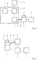
- an air supply system has a compressor 2 operated by an engine 1.
- the compressor 2 is assigned an air dryer system 3 for dehumidifying the compressed air generated.
- the motor 1 is a three-phase motor and the compressor 2 is a single-stage screw compressor.
- the air dryer system 3 works according to the adsorption drying principle.
- various analog and digital sensors 5 are assigned to the compressor 2, which sensors receive various information and feed it to the electronic converter 4 via a sensor line 9.
- the motor 1 as well as the compressor 2 and the sensors 5 are arranged inside a metallic capsule 8.
- the sensor line 9 arranged between sensors 5 and electronic converter 4 has a shield 10 between metallic capsule 8 and electronic converter 4.
- the electrical signals generated by the sensors 5 are used for control purposes of the electronic converter 4 and monitoring of the compressor 2 are used.
- the electrical signals generated by the sensors 5 are processed into bus signals. These bus signals are provided at a bus interface 6 for evaluation.
- a central brake control device 7 the control commands comprehensive software for recognizing limit values and generating warning signals is stored.
- FIG. 2 Another air drying system according to the invention is shown, the electronic converter 4 being attached directly to the motor 1.
- the motor drives the compressor 2 to generate compressed air.
- the air dryer system 3 has the task of dehumidifying the compressed air generated.
- the control commands comprehensive software for the detection of limit values and the generation of warning signals is implemented in the programmable logic controller of the electronic converter 4.
- the electrical connection between sensors 5 and electronic converter 4 takes place via sensor line 9 having shielding 10.
- the invention is not restricted to the preferred exemplary embodiment described above. Rather, modifications thereof are also conceivable, which are also covered by the scope of protection of the following claims.
- the compressor can be a two-stage oil-free or oil-lubricated piston compressor.
Description
Die vorliegende Erfindung betrifft eine Luftversorgungsanlage umfassend einen von einem Motor angetriebenen Kompressor zur Erzeugung von Druckluft, einer Lufttrockneranlage zum Entfeuchten der erzeugten Druckluft, einen elektronischen Umrichter zur bedarfsabhängigen Kompressorsteuerung und mehrere analoge und/oder digitale Sensoren zur Generierung von elektrischen Signalen.The present invention relates to an air supply system comprising a compressor driven by a motor to generate compressed air, an air dryer system for dehumidifying the compressed air generated, an electronic converter for demand-dependent compressor control and several analog and / or digital sensors for generating electrical signals.
Das Einsatzgebiet der Erfindung erstreckt sich auf Schienenfahrzeuge, deren Druckluftversorgungssystem in erster Linie für die Bereitstellung eines Bremsdrucks für die Fahrzeugbremsen dient.The field of application of the invention extends to rail vehicles whose compressed air supply system is primarily used to provide brake pressure for the vehicle brakes.
Aus dem allgemein bekannten Stand der Technik geht hervor, dass Kompressorantriebe für Luftversorgungsanlagen in Schienenfahrzeugen von sogenannten Hilfsbetriebeumrichtern gespeist werden. Dabei sorgt ein Eingangsumrichter für die Anpassung der Eingangsspannung und eine Vielzahl von Ausgangsumrichtern nehmen die Anpassung an die verschiedenen Verbraucher vor. Durch den Hilfsbetriebeumrichter wird nicht nur die Luftversorgungsanlage bedient, sondern auch weitere Geräte wie zum Beispiel Gerätelüfter und Klimaanlagen.The generally known prior art shows that compressor drives for air supply systems in rail vehicles are fed by so-called auxiliary converters. An input converter takes care of the adaptation of the input voltage and a large number of output converters adapt to the various consumers. The auxiliary converter not only serves the air supply system, but also other devices such as device fans and air conditioning systems.
Gesonderte Umrichter die den Antrieb des Kompressors der Luftversorgungsanlage speisen, sind insbesondere in Schienenfahrzeugen eine Ausnahme. Sofern Diagnoeinrichtungen für den Kompressor zum Einsatz kommen, werden diese als zusätzliche Steuergeräte unabhängig vom Umrichter ausgeführt. Darüber hinaus sind, insbesondere für den Bahnbetrieb ausgelegte Umrichter groß in ihrer Abmessung und beanspruchen dadurch viel Bauraum bei meist hohem Gewicht. Eine Tendenz die sich in der Antriebstechnik im zunehmenden Maße durchsetzt ist, dass jeder Verbraucher seinen eigenen Umrichter erhält. Dadurch entstehen neue Möglichkeiten der Steuerung, wobei durch zusätzliche im Umrichter integrierte Elektronik die Gerätediagnose und Signalverarbeitung über den Umrichter realisiert werden kann.Separate converters that feed the drive of the compressor of the air supply system are an exception, especially in rail vehicles. If diagnostic devices are used for the compressor, they are designed as additional control devices independent of the converter. In addition, converters designed especially for rail operations are large in size and therefore take up a lot of installation space and are usually heavy. A tendency that is becoming increasingly common in drive technology is that each consumer receives its own converter. This creates new control options, with additional electronics integrated in the converter enabling device diagnostics and signal processing to be implemented via the converter.
Aus der
Die
Es ist daher die Aufgabe der vorliegenden Erfindung eine Luftversorgungsanlage eines Schienenfahrzeuges zur Verfügung zu stellen, die die Drehzahl des Kompressors bedarfsabhängig steuert, aber auch Signale der Diagnose des Kompressors verarbeitet.It is therefore the object of the present invention to provide an air supply system for a rail vehicle which controls the speed of the compressor as required, but also processes signals from the diagnosis of the compressor.
Erfindungsgemäß sind die elektrischen Signale zur Steuerung des elektronischen Umrichters und zur Überwachung und Steuerung des Kompressors nutzbar, wobei in dem elektronischen Umrichter eine Verarbeitung der von den Sensoren generierten elektrischen Signale zu Bussignalen erfolgt, welche zur Auswertung an einer Busschnittstelle bereitstellbar sind. Vorzugsweise verarbeitet der elektronische Umrichter die elektrischen Signale zu einem CAN-Bussignal. Es können gesonderte Steuergeräte zur elektronischen Überwachung des Kompressors und des Motors eingespart werden. Darüber hinaus wird die Möglichkeit geschaffen, Diagnosesignale der Kompressorsteuerung intelligent mit anderen Diagnose- und Steuersignalen des Umrichters zu koppeln, weiterzuverarbeiten und vorteilhafte Betriebszustände durch Kommunikation unter den Steuergeräten für den Kompressor und/oder die Luftversorgungsanlage herzustellen.According to the invention, the electrical signals can be used to control the electronic converter and to monitor and control the compressor, the electrical signals generated by the sensors being processed in the electronic converter into bus signals which can be provided for evaluation at a bus interface. The electronic converter preferably processes the electrical signals into a CAN bus signal. Separate control units for electronic monitoring of the compressor and the motor can be saved. In addition, the possibility is created to intelligently couple diagnostic signals of the compressor control with other diagnostic and control signals of the converter, to process them further and to establish advantageous operating states through communication between the control devices for the compressor and / or the air supply system.
Die Erfindung schließt die technische Lehre ein, dass der elektronische Umrichter ein Frequenzumrichter mit einer speicherprogrammierbaren Steuerung ist. Über die integrierte speicherprogrammierbare Steuerung wird ein benutzerdefiniertes Steuerprogramm in den elektronischen Umrichter implementiert. Dieses Programm liest die Signale an Analog- und Digitaleingängen ein, verarbeitet sie weiter und regelt je nach Programmierung die Ausgangsfrequenz. Der elektronische Umrichter verfügt vorzugsweise über acht analoge Eingänge zur Verarbeitung der Sensorsignale für die Überwachung des Kompressors.The invention includes the technical teaching that the electronic converter is a frequency converter with a programmable controller. A user-defined control program is implemented in the electronic converter via the integrated programmable logic controller. This program reads the signals at the analog and digital inputs, processes them and controls them depending on the programming Output frequency. The electronic converter preferably has eight analog inputs for processing the sensor signals for monitoring the compressor.
Gemäß einem bevorzugten Ausführungsbeispiel ist die Steuerbefehle umfassende Software zur Erkennung von Grenzwerten und Erzeugung von Warnsignalen in einem zentralen Bremssteuergerät hinterlegt. In einer bevorzugten Variante wird eine Masterfunktion direkt von dem zentralen Bremssteuergerät ausgeführt. Auf diese Weise entfällt die Entwicklung einer kompressorspezifischen Auswertehardware. Ein Grenzwerterkennung berechnendes und Warnsignale erzeugendes Programm mit einer Auswertesoftware wird vorzugsweise in einem Bus-Master hinterlegt.According to a preferred exemplary embodiment, the software comprising control commands for recognizing limit values and generating warning signals is stored in a central brake control device. In a preferred variant, a master function is carried out directly by the central brake control device. In this way, there is no need to develop any compressor-specific evaluation hardware. A program that calculates limit value recognition and generates warning signals with evaluation software is preferably stored in a bus master.
Gemäß einem weiteren bevorzugten Ausführungsbeispiel ist eine Steuerbefehle umfassende Software zur Erkennung von Grenzwerten und Erzeugung von Warnsignalen in der speicherprogrammierbaren Steuerung des elektronischen Umrichters implementiert. Der Vorteil der Ausführung mit Umrichter ist eine Entlastung der Rechenleistung eines Masters (BSG), da dieser nur noch die Signale weiterleitet und eine Berechnung somit entfällt.According to a further preferred exemplary embodiment, software comprising control commands for recognizing limit values and generating warning signals is implemented in the programmable logic controller of the electronic converter. The advantage of the version with converter is that the computing power of a master (BSG) is relieved, as it only forwards the signals and therefore no calculation is required.
Vorzugsweise ist der Kompressor ein zweistufiger ölfreier oder ölgeschmierter Kolbenkompressor. Ein einstufiger ölfreier oder ölgeschmierter Kolbenverdichter ist ebenfalls denkbar. Die Überwachung des Kompressors besteht bei zweistufigen ölfreien Kolbenkompressoren aus Sensoren, die insbesondere mindestens eine Zylinderwandtemperatur, eine Kühllufttemperatur, eine Ansaugtemperatur, sowie Drücke, wie einen Enddruck, einen Zwischendruck und einen Unterdruck an den Ansaugfilter überwachen. Bei ölgeschmierten Kompressoren hingegen ist es zusätzlich sinnvoll insbesondere eine Öltemperatur und eine Luftaustrittstemperatur zu überwachen.The compressor is preferably a two-stage oil-free or oil-lubricated piston compressor. A single-stage oil-free or oil-lubricated piston compressor is also conceivable. In two-stage oil-free piston compressors, the monitoring of the compressor consists of sensors that in particular monitor at least one cylinder wall temperature, one cooling air temperature, one intake temperature and pressures such as a final pressure, an intermediate pressure and a negative pressure on the intake filter. In the case of oil-lubricated compressors, on the other hand, it is also useful to monitor an oil temperature and an air outlet temperature.
Des Weiteren bevorzugt ist, dass der Kompressor ein Rotationsverdichter ist. Der Kompressor ist vorzugsweise ein einstufiger Schraubenkompressor.It is also preferred that the compressor is a rotary compressor. The compressor is preferably a single-stage screw compressor.
Gemäß einer die Erfindung weiter verbessernden Maßnahme wird vorgeschlagen, dass der elektronische Umrichter direkt an dem Motor befestigt ist. Dadurch lässt sich eine kompakte Bauart realisieren.According to a measure which further improves the invention, it is proposed that the electronic converter be attached directly to the motor. This enables a compact design to be implemented.
Gemäß einem bevorzugten Ausführungsbeispiel sind der Motor und der Kompressor in einer metallischen Kapsel angeordnet, wobei zwischen der metallischen Kapsel und dem elektronischen Umrichter angeordnete und somit außerhalb der metallischen Kapsel verlaufende Sensorleitungen über eine Schirmung zur Abschirmung gegen elektromagnetische Störungen verfügen. Ein elektronischer Umrichter erzeugt bauartbedingt elektromagnetische Störungen. Diese können in den Sensorleitungen der Diagnosesignale zu Störungen führen und falsche Signale hervorrufen. Die geschirmten Sensorleitungen werden an der metallischen Kapsel vorzugsweise mittels Stecker befestigt. Innerhalb der metallischen Kapsel werden die Kabel ungeschirmt weitergeführt, da die Kapsel selbst als Schirmung dient. Abhängig von dem vorhandenen Bauraum ist es auch denkbar, den Umrichter innerhalb der Kapsel unterzubringen.According to a preferred exemplary embodiment, the motor and the compressor are arranged in a metal capsule, sensor lines arranged between the metal capsule and the electronic converter and thus extending outside the metal capsule having a shield for shielding against electromagnetic interference. An electronic converter generates electromagnetic interference due to its design. These can lead to faults in the sensor lines of the diagnostic signals and cause false signals. The shielded sensor lines are attached to the metal capsule, preferably by means of a plug. The cables are routed unshielded within the metallic capsule, as the capsule itself serves as a shield. Depending on the space available, it is also conceivable to accommodate the converter within the capsule.
Vorzugsweise bestehen die Sensorleitungen aus Einzellitzen mit Schirmung. Aus der metallischen Kapsel werden Sensorsignale geschirmt zum Umrichter geführt. Bei Verwendung eines mehradrigen geschirmten Kabels kann der Schirm nicht bis an die Steckerleisten im elektronischen Umrichter geführt werden. Es erweist sich als besonders vorteilhaft, jedes einzelne Sensorsignal über ein Kabel vorzugsweise durch Sammelverschraubungen an einem Gehäuse des elektronischen Umrichters zu führen.The sensor lines preferably consist of individual strands with shielding. Sensor signals are shielded from the metal capsule and lead to the converter. If a multi-core shielded cable is used, the shield cannot be led to the connector strips in the electronic converter. It has proven to be particularly advantageous to route each individual sensor signal via a cable, preferably through collective screw connections on a housing of the electronic converter.
Des Weiteren bevorzugt ist, dass der Motor ein Drehstrommotor ist. Drehstrommotoren weisen im Vergleich zu Gleichstrommotoren eine geringere Baugröße und somit eine höhere Leistungsdichte auf. Außerdem arbeiten Drehstrommotoren verschleißfrei, da ein Bürstenverschleiß entfällt. Darüber hinaus weisen Elektromotoren im Betrieb geringere Schallemissionen auf.It is also preferred that the motor is a three-phase motor. In comparison to DC motors, three-phase motors are smaller in size and therefore have a higher power density. In addition, three-phase motors work wear-free, since there is no brush wear. In addition, electric motors produce lower noise emissions during operation.
Weitere, die Erfindung verbessernde Maßnahmen werden nachstehend gemeinsam mit der Beschreibung eines bevorzugten Ausführungsbeispiels der Erfindung anhand der Figuren näher dargestellt. Es zeigen:
- Fig. 1
- ein vereinfachtes Blockschaltbild einer erfindungsgemäßen Lufttrocknungsanlage mit einer metallischen Kapsel, und
- Fig.2
- ein vereinfachtes Blockschaltbild einer erfindungsgemäßen Lufttrocknungsanlage mit einem an einem Motor angeordnetem elektronischen Umrichter.
- Fig. 1
- a simplified block diagram of an air drying system according to the invention with a metallic capsule, and
- Fig.2
- a simplified block diagram of an air drying system according to the invention with an electronic converter arranged on a motor.
Gemäß
In
Die Erfindung ist nicht beschränkt auf das vorstehend beschriebene bevorzugte Ausführungsbeispiel. Es sind vielmehr auch Abwandlungen hiervon denkbar, welche vom Schutzbereich der nachfolgenden Ansprüche mit umfasst sind. So ist es beispielsweise auch möglich, die Sensorleitung 9 aus mehreren Einzellitzen auszubilden, die sofern erforderlich eine Schirmung 10 aufweisen. Ferner kann der Kompressor ein zweistufiger ölfreier oder ölgeschmierter Kolbenkompressor sein.The invention is not restricted to the preferred exemplary embodiment described above. Rather, modifications thereof are also conceivable, which are also covered by the scope of protection of the following claims. For example, it is also possible to form the
Ergänzend ist darauf hinzuweisen, dass "umfassend" keine anderen Elemente oder Schritte ausschließt und "eine" oder "ein" keine Vielzahl ausschließt. Ferner sei darauf hingewiesen, dass Merkmale oder Schritte, die mit Verweis auf eines der obigen Ausführungsbeispiele beschrieben worden sind, auch in Kombination mit anderen Merkmalen oder Schritten anderer oben beschriebener Ausführungsbeispiele verwendet werden können. Bezugszeichen in den Ansprüchen sind nicht als Einschränkung anzusehen.In addition, it should be pointed out that “comprising” does not exclude any other elements or steps and “a” or “an” does not exclude a plurality. It should also be noted that features or steps that have been described with reference to one of the above exemplary embodiments can also be used in combination with other features or steps of other exemplary embodiments described above. Reference signs in the claims are not to be viewed as a restriction.
- 11
- Motorengine
- 22
- Kompressorcompressor
- 33
- LufttrockneranlageAir dryer system
- 44th
- elektronischer Umrichterelectronic converter
- 55
- Sensorsensor
- 66
- BusschnittstelleBus interface
- 77th
- BremssteuergerätBrake control unit
- 88th
- metallische Kapselmetallic capsule
- 99
- SensorleitungSensor cable
- 1010
- SchirmungShielding
Claims (10)
- Rail vehicle with a compressed air supply system for the provision of a brake pressure for vehicle brakes with an air supply system, comprising a compressor (2) driven by a motor (1) for generating compressed air, an air drier system (3) for extracting moisture from the compressed air produced, an electronic converter (4) for demand-based compressor control and a plurality of analogue and/or digital sensors (5) for producing electrical signals,
characterised in that the electrical signals can be used for controlling the electronic converter (4) and for monitoring and controlling the compressor (2), and the processing of the electrical signals produced by the sensors (5) is carried out in the electronic converter (4) to form bus signals which can be provided for evaluation at a bus interface (6). - Rail vehicle according to claim 1,
characterised in that the electronic converter (4) is a frequency converter with a programmable logic controller. - Rail vehicle according to claim 1 or 2,
characterised in that software comprising control commands for detecting limit values and generating warning signals is implemented in the programmable logic controller of the electronic converter (4). - Rail vehicle according to claim 1,
characterised in that the software comprising control commands for detecting limit values and generating warning signals is stored in a central brake control unit (7). - Rail vehicle according to claim 1,
characterised in that the compressor (2) is a two-stage oil-free or oil-lubricated piston compressor. - Rail vehicle according to claim 1,
characterised in that the compressor (2) is a rotation compressor. - Rail vehicle according to claim 1,
characterised in that the electronic converter (4) is directly attached to the motor (1). - Rail vehicle according to claim 1,
characterised in that the motor (1) and the compressor (2) are arranged in a metallic capsule (8), wherein sensor lines (9) arranged between the metallic capsule (8) and the electronic converter (4) and thus extending outside of the metallic capsule (8) have screening (10) for shielding them against electromagnetic interference. - Rail vehicle according to claim 8,
characterised in that the sensor lines (9) consist of single strands with screening. - Rail vehicle according to claim 1,
characterised in that the motor (1) is a three-phase motor.
Priority Applications (1)
| Application Number | Priority Date | Filing Date | Title |
|---|---|---|---|
| PL14703843T PL2956341T5 (en) | 2013-02-14 | 2014-02-11 | Air supply system with electronic converter |
Applications Claiming Priority (2)
| Application Number | Priority Date | Filing Date | Title |
|---|---|---|---|
| DE102013101502.6A DE102013101502A1 (en) | 2013-02-14 | 2013-02-14 | Air supply system with electronic converter |
| PCT/EP2014/052599 WO2014124920A1 (en) | 2013-02-14 | 2014-02-11 | Air supply system with electronic converter |
Publications (3)
| Publication Number | Publication Date |
|---|---|
| EP2956341A1 EP2956341A1 (en) | 2015-12-23 |
| EP2956341B1 EP2956341B1 (en) | 2016-11-30 |
| EP2956341B2 true EP2956341B2 (en) | 2020-08-12 |
Family
ID=50073188
Family Applications (1)
| Application Number | Title | Priority Date | Filing Date |
|---|---|---|---|
| EP14703843.4A Active EP2956341B2 (en) | 2013-02-14 | 2014-02-11 | Air supply system with electronic converter |
Country Status (10)
| Country | Link |
|---|---|
| US (1) | US11300117B2 (en) |
| EP (1) | EP2956341B2 (en) |
| JP (1) | JP6448552B2 (en) |
| KR (1) | KR102157405B1 (en) |
| CN (1) | CN105008194B (en) |
| DE (1) | DE102013101502A1 (en) |
| ES (1) | ES2617703T5 (en) |
| PL (1) | PL2956341T5 (en) |
| RU (1) | RU2646961C2 (en) |
| WO (1) | WO2014124920A1 (en) |
Families Citing this family (10)
| Publication number | Priority date | Publication date | Assignee | Title |
|---|---|---|---|---|
| DE102015107552A1 (en) | 2015-05-13 | 2016-11-17 | Knorr-Bremse Systeme für Schienenfahrzeuge GmbH | Central monitoring of an air supply system for rail vehicles |
| DE102016106331A1 (en) | 2016-04-07 | 2017-10-12 | Knorr-Bremse Systeme für Schienenfahrzeuge GmbH | Device for controlling an air supply system of a vehicle, in particular a rail vehicle |
| DE102016111100A1 (en) | 2016-06-17 | 2017-12-21 | Knorr-Bremse Systeme für Schienenfahrzeuge GmbH | Valve device for increasing the performance of multistage compressor units |
| DE102016111101A1 (en) * | 2016-06-17 | 2017-12-21 | Knorr-Bremse Systeme für Schienenfahrzeuge GmbH | Method and device for vibration compensation in a reciprocating compressor |
| DE102016117327A1 (en) | 2016-09-15 | 2018-03-15 | Knorr-Bremse Systeme für Schienenfahrzeuge GmbH | Auxiliary unit for a locomotive |
| DE102016011502A1 (en) * | 2016-09-21 | 2018-03-22 | Knorr-Bremse Systeme für Nutzfahrzeuge GmbH | Compressor system for a commercial vehicle |
| IT201700042515A1 (en) * | 2017-04-18 | 2018-10-18 | D V P Vacuum Tech S P A | MONITORING SYSTEM FOR A PNEUMOFORA OPERATING MACHINE. |
| EP3530530A1 (en) * | 2018-02-26 | 2019-08-28 | Filkar Otomotiv sanayi ve Ticaret Anonim Sirketi | A brake system with a control unit |
| DE102018215108A1 (en) * | 2018-09-05 | 2020-03-05 | Knorr-Bremse Systeme für Schienenfahrzeuge GmbH | System for diagnosis and monitoring of air supply systems and their components |
| DE102019104760A1 (en) * | 2019-02-25 | 2020-08-27 | Knorr-Bremse Systeme für Schienenfahrzeuge GmbH | Air supply system and method for controlling and / or monitoring an air supply system |
Citations (11)
| Publication number | Priority date | Publication date | Assignee | Title |
|---|---|---|---|---|
| EP0872342A2 (en) † | 1997-04-17 | 1998-10-21 | MAN Roland Druckmaschinen AG | Suction and/or blower system for a printing press |
| US20060275143A1 (en) † | 2005-05-20 | 2006-12-07 | Copeland Corporation | Sensor for hermetic machine |
| DE102007056318A1 (en) † | 2007-04-12 | 2008-10-16 | Deere & Company, Moline | Communication system of a vehicle and method for operating a communication system |
| US20090254246A1 (en) † | 2008-04-02 | 2009-10-08 | International Truck Intellectual Property Company, Llc | Method and apparatus to optimize energy efficiency of air compressor in vehicle air brake application |
| EP1993893B1 (en) † | 2006-03-08 | 2010-05-19 | Knorr-Bremse Systeme für Schienenfahrzeuge GmbH | Compressor assembly |
| EP0976635B2 (en) † | 1998-07-31 | 2011-01-19 | KNORR-BREMSE Systeme für Nutzfahrzeuge GmbH | Compressed-air supply device for vehicle compressed air systems and method for power conserving at compressed air processing system |
| DE102009052510A1 (en) † | 2009-11-11 | 2011-05-12 | Kübrich Ingenieurgesellschaft Mbh & Co. Kg | Compressor for generating compressed air |
| DE102010020266A1 (en) † | 2010-05-11 | 2011-11-17 | Knorr-Bremse Systeme für Nutzfahrzeuge GmbH | Device for controlling e.g. parking brake system in utility vehicle that is utilized for trailer operation, has brake control unit in which control routines are implemented for controlling load, regeneration and relief phases by valves |
| EP2388172A1 (en) † | 2010-05-20 | 2011-11-23 | Siemens Aktiengesellschaft | Electropneumatic towing module for rail vehicles |
| CN102588259A (en) † | 2012-03-01 | 2012-07-18 | 娄卡奔新能源科技发展(上海)有限公司 | Frequency conversion and constant voltage control device of air compressor unit for cement plant |
| EP2553537B1 (en) † | 2010-07-09 | 2015-07-29 | Siemens Aktiengesellschaft | Monitoring and diagnostic system for a fluid energy machine system and fluid energy machine system |
Family Cites Families (23)
| Publication number | Priority date | Publication date | Assignee | Title |
|---|---|---|---|---|
| DE3445699A1 (en) * | 1984-12-14 | 1986-06-19 | Knorr-Bremse AG, 8000 München | AIR DRYING DEVICE FOR COMPRESSED AIR SYSTEMS |
| JPH01292710A (en) | 1988-05-19 | 1989-11-27 | Hitachi Cable Ltd | Manufacture of cable core |
| JP3300770B2 (en) * | 1993-02-19 | 2002-07-08 | 株式会社日立製作所 | Variable displacement compressor |
| JPH08219058A (en) | 1995-02-09 | 1996-08-27 | Matsushita Electric Ind Co Ltd | Hermetic motor-driven compressor |
| DE19515895A1 (en) * | 1995-04-29 | 1996-10-31 | Bosch Gmbh Robert | Compressed air supply device for vehicle compressed air systems and method for controlling the compressed air supply device |
| DE19631300A1 (en) | 1996-08-02 | 1998-02-05 | Alcatel Kabel Ag | Arrangement for inserting the end of a shielded electrical line into a metallic housing |
| RU2151326C1 (en) * | 1997-11-20 | 2000-06-20 | ЗАО ППТФ "Элма-Ко" | Hermetic compressor with adjustable refrigerating capacity |
| JP3966008B2 (en) | 2002-02-15 | 2007-08-29 | 株式会社豊田自動織機 | Compressor unit |
| RU2254249C2 (en) * | 2003-09-09 | 2005-06-20 | Российский государственный открытый технический университет путей сообщения Министерства путей сообщения Российской Федерации (РГОТУПС) | System to control pressure in pneumatic system of traction vehicle |
| US7475556B2 (en) * | 2004-03-15 | 2009-01-13 | Parker Hannifin Corporation | System and apparatus controlling a variable speed compressor system |
| US7260949B2 (en) * | 2004-10-20 | 2007-08-28 | Ingersoll-Rand Company | Compressor variable dryer system |
| DE102006007743B4 (en) | 2006-02-20 | 2016-03-17 | Knorr-Bremse Systeme für Nutzfahrzeuge GmbH | Reciprocating compressor with non-contact gap seal |
| JP4844467B2 (en) * | 2007-05-07 | 2011-12-28 | 日産自動車株式会社 | Exhaust gas purification device for internal combustion engine |
| US8774972B2 (en) * | 2007-05-14 | 2014-07-08 | Flowserve Management Company | Intelligent pump system |
| JP2009197701A (en) | 2008-02-22 | 2009-09-03 | Dainippon Printing Co Ltd | Facility operation monitor control device, program and recording medium |
| DE102009050720B4 (en) | 2009-10-26 | 2012-09-20 | Bombardier Transportation Gmbh | Control device for a compressor device |
| JP2011102674A (en) * | 2009-11-11 | 2011-05-26 | Mitsubishi Electric Corp | Air conditioning machine |
| CN101725515B (en) * | 2009-11-12 | 2013-08-07 | 厦门市万树科技有限公司 | Air compressor energy-saving control method |
| JP5189120B2 (en) | 2010-03-08 | 2013-04-24 | 日立オートモティブシステムズ株式会社 | Power converter |
| ES2548873T3 (en) * | 2010-12-24 | 2015-10-21 | Mayekawa Mfg. Co., Ltd. | Procedure and device to control the operation of a heat pump device |
| DE102010056567A1 (en) * | 2010-12-30 | 2012-07-05 | Hydac Cooling Gmbh | Liquid-air cooling system |
| US9337833B2 (en) * | 2011-11-14 | 2016-05-10 | Atmel Corporation | Driven shield for shaping an electric field of a touch sensor |
| US20130280095A1 (en) * | 2012-04-20 | 2013-10-24 | General Electric Company | Method and system for reciprocating compressor starting |
-
2013
- 2013-02-14 DE DE102013101502.6A patent/DE102013101502A1/en not_active Ceased
-
2014
- 2014-02-11 US US14/765,195 patent/US11300117B2/en active Active
- 2014-02-11 WO PCT/EP2014/052599 patent/WO2014124920A1/en active Application Filing
- 2014-02-11 JP JP2015557397A patent/JP6448552B2/en active Active
- 2014-02-11 PL PL14703843T patent/PL2956341T5/en unknown
- 2014-02-11 ES ES14703843T patent/ES2617703T5/en active Active
- 2014-02-11 CN CN201480008877.3A patent/CN105008194B/en active Active
- 2014-02-11 EP EP14703843.4A patent/EP2956341B2/en active Active
- 2014-02-11 RU RU2015138905A patent/RU2646961C2/en active
- 2014-02-11 KR KR1020157023784A patent/KR102157405B1/en active IP Right Grant
Patent Citations (11)
| Publication number | Priority date | Publication date | Assignee | Title |
|---|---|---|---|---|
| EP0872342A2 (en) † | 1997-04-17 | 1998-10-21 | MAN Roland Druckmaschinen AG | Suction and/or blower system for a printing press |
| EP0976635B2 (en) † | 1998-07-31 | 2011-01-19 | KNORR-BREMSE Systeme für Nutzfahrzeuge GmbH | Compressed-air supply device for vehicle compressed air systems and method for power conserving at compressed air processing system |
| US20060275143A1 (en) † | 2005-05-20 | 2006-12-07 | Copeland Corporation | Sensor for hermetic machine |
| EP1993893B1 (en) † | 2006-03-08 | 2010-05-19 | Knorr-Bremse Systeme für Schienenfahrzeuge GmbH | Compressor assembly |
| DE102007056318A1 (en) † | 2007-04-12 | 2008-10-16 | Deere & Company, Moline | Communication system of a vehicle and method for operating a communication system |
| US20090254246A1 (en) † | 2008-04-02 | 2009-10-08 | International Truck Intellectual Property Company, Llc | Method and apparatus to optimize energy efficiency of air compressor in vehicle air brake application |
| DE102009052510A1 (en) † | 2009-11-11 | 2011-05-12 | Kübrich Ingenieurgesellschaft Mbh & Co. Kg | Compressor for generating compressed air |
| DE102010020266A1 (en) † | 2010-05-11 | 2011-11-17 | Knorr-Bremse Systeme für Nutzfahrzeuge GmbH | Device for controlling e.g. parking brake system in utility vehicle that is utilized for trailer operation, has brake control unit in which control routines are implemented for controlling load, regeneration and relief phases by valves |
| EP2388172A1 (en) † | 2010-05-20 | 2011-11-23 | Siemens Aktiengesellschaft | Electropneumatic towing module for rail vehicles |
| EP2553537B1 (en) † | 2010-07-09 | 2015-07-29 | Siemens Aktiengesellschaft | Monitoring and diagnostic system for a fluid energy machine system and fluid energy machine system |
| CN102588259A (en) † | 2012-03-01 | 2012-07-18 | 娄卡奔新能源科技发展(上海)有限公司 | Frequency conversion and constant voltage control device of air compressor unit for cement plant |
Non-Patent Citations (1)
| Title |
|---|
| "Interne Kompressor- Steuerung Sigma Control", KAESER KOMPRESSOREN, 2004 † |
Also Published As
| Publication number | Publication date |
|---|---|
| KR102157405B1 (en) | 2020-09-17 |
| ES2617703T5 (en) | 2021-06-07 |
| RU2015138905A (en) | 2017-03-20 |
| CN105008194A (en) | 2015-10-28 |
| WO2014124920A1 (en) | 2014-08-21 |
| PL2956341T3 (en) | 2017-06-30 |
| KR20150118175A (en) | 2015-10-21 |
| EP2956341A1 (en) | 2015-12-23 |
| US20150369235A1 (en) | 2015-12-24 |
| PL2956341T5 (en) | 2020-11-16 |
| US11300117B2 (en) | 2022-04-12 |
| ES2617703T3 (en) | 2017-06-19 |
| EP2956341B1 (en) | 2016-11-30 |
| JP6448552B2 (en) | 2019-01-09 |
| DE102013101502A1 (en) | 2014-08-14 |
| RU2646961C2 (en) | 2018-03-12 |
| JP2016514227A (en) | 2016-05-19 |
| CN105008194B (en) | 2017-08-29 |
Similar Documents
| Publication | Publication Date | Title |
|---|---|---|
| EP2956341B2 (en) | Air supply system with electronic converter | |
| EP3516218B1 (en) | Compressor system for a work vehicle | |
| DE102005016855A1 (en) | Interface module for arrangement in or on a motor | |
| WO2017041930A1 (en) | Method for performing a diagnosis in a motor vehicle | |
| EP3078112B1 (en) | Actuator with position sensor | |
| DE102008016048A1 (en) | Process control system of an automation system | |
| DE102010050820A1 (en) | Device for driving an electric motor for a power steering system | |
| EP3268822B1 (en) | Projecting device and method for configuring and/or parameterising automation components of an automation system | |
| DE102008043300A1 (en) | Control device of a fan and air conditioning module for motor vehicles | |
| EP3847512B1 (en) | System for the diagnosis and monitoring of air supply systems and components thereof | |
| EP2013731B1 (en) | Circuit arrangement, and method for the operation of a circuit arrangement | |
| DE102014212795B4 (en) | Position sensor for detecting a position of an actuator | |
| DE10359875A1 (en) | Digital network for vehicle, has sensor/actuators connected to data bus coupled controllers | |
| EP3043222B1 (en) | Analysis system for measuring and analyzing industrial machinery or installations | |
| DE102019003477A1 (en) | Method for towing a vehicle | |
| DE102018103873A1 (en) | Control unit for an electric motor and actuator | |
| EP3088737B1 (en) | Vacuum pump and method for producing a vacuum pump | |
| DE102016206348B4 (en) | Electrical circuit arrangement for controlling electromechanical assistance drives | |
| DE102017111651A1 (en) | Drive unit of an automation component, in particular a gripping, tensioning and alternating or pivoting unit | |
| WO2023174631A1 (en) | Electrified motor vehicle with a central component-specific energy monitoring function | |
| DE102022110638A1 (en) | DIAGNOSTIC DEVICE, DIAGNOSTIC METHOD, DIAGNOSTIC PROGRAM AND POWER CONVERTER WITH DIAGNOSTIC DEVICE | |
| DE102021006193A1 (en) | Sensor and method for monitoring an electrically operated drive system using a sensor | |
| DE102014223895A1 (en) | Electronic arrangement in a motor vehicle | |
| DE102007023190A1 (en) | Sensor interface, particularly for brake module or gear shift actuator, for connection of multiple sensors to control device, has number of control device connections, which are factor smaller than number of sensor connections | |
| DE102012009138A1 (en) | Vehicle-diagnostic connector for communication network, has control unit, where control unit and vehicle-diagnostic connector are connected with each other over diagnosis line |
Legal Events
| Date | Code | Title | Description |
|---|---|---|---|
| PUAI | Public reference made under article 153(3) epc to a published international application that has entered the european phase |
Free format text: ORIGINAL CODE: 0009012 |
|
| 17P | Request for examination filed |
Effective date: 20150914 |
|
| AK | Designated contracting states |
Kind code of ref document: A1 Designated state(s): AL AT BE BG CH CY CZ DE DK EE ES FI FR GB GR HR HU IE IS IT LI LT LU LV MC MK MT NL NO PL PT RO RS SE SI SK SM TR |
|
| AX | Request for extension of the european patent |
Extension state: BA ME |
|
| DAX | Request for extension of the european patent (deleted) | ||
| GRAP | Despatch of communication of intention to grant a patent |
Free format text: ORIGINAL CODE: EPIDOSNIGR1 |
|
| INTG | Intention to grant announced |
Effective date: 20160819 |
|
| GRAS | Grant fee paid |
Free format text: ORIGINAL CODE: EPIDOSNIGR3 |
|
| GRAA | (expected) grant |
Free format text: ORIGINAL CODE: 0009210 |
|
| AK | Designated contracting states |
Kind code of ref document: B1 Designated state(s): AL AT BE BG CH CY CZ DE DK EE ES FI FR GB GR HR HU IE IS IT LI LT LU LV MC MK MT NL NO PL PT RO RS SE SI SK SM TR |
|
| REG | Reference to a national code |
Ref country code: CH Ref legal event code: EP Ref country code: GB Ref legal event code: FG4D Free format text: NOT ENGLISH |
|
| REG | Reference to a national code |
Ref country code: AT Ref legal event code: REF Ref document number: 849487 Country of ref document: AT Kind code of ref document: T Effective date: 20161215 |
|
| REG | Reference to a national code |
Ref country code: IE Ref legal event code: FG4D Free format text: LANGUAGE OF EP DOCUMENT: GERMAN |
|
| REG | Reference to a national code |
Ref country code: DE Ref legal event code: R096 Ref document number: 502014002091 Country of ref document: DE |
|
| REG | Reference to a national code |
Ref country code: CH Ref legal event code: NV Representative=s name: ISLER AND PEDRAZZINI AG, CH |
|
| REG | Reference to a national code |
Ref country code: FR Ref legal event code: PLFP Year of fee payment: 4 |
|
| PG25 | Lapsed in a contracting state [announced via postgrant information from national office to epo] |
Ref country code: LV Free format text: LAPSE BECAUSE OF FAILURE TO SUBMIT A TRANSLATION OF THE DESCRIPTION OR TO PAY THE FEE WITHIN THE PRESCRIBED TIME-LIMIT Effective date: 20161130 |
|
| REG | Reference to a national code |
Ref country code: SE Ref legal event code: TRGR |
|
| REG | Reference to a national code |
Ref country code: LT Ref legal event code: MG4D |
|
| REG | Reference to a national code |
Ref country code: NL Ref legal event code: MP Effective date: 20161130 |
|
| PG25 | Lapsed in a contracting state [announced via postgrant information from national office to epo] |
Ref country code: GR Free format text: LAPSE BECAUSE OF FAILURE TO SUBMIT A TRANSLATION OF THE DESCRIPTION OR TO PAY THE FEE WITHIN THE PRESCRIBED TIME-LIMIT Effective date: 20170301 Ref country code: NO Free format text: LAPSE BECAUSE OF FAILURE TO SUBMIT A TRANSLATION OF THE DESCRIPTION OR TO PAY THE FEE WITHIN THE PRESCRIBED TIME-LIMIT Effective date: 20170228 Ref country code: LT Free format text: LAPSE BECAUSE OF FAILURE TO SUBMIT A TRANSLATION OF THE DESCRIPTION OR TO PAY THE FEE WITHIN THE PRESCRIBED TIME-LIMIT Effective date: 20161130 |
|
| PG25 | Lapsed in a contracting state [announced via postgrant information from national office to epo] |
Ref country code: RS Free format text: LAPSE BECAUSE OF FAILURE TO SUBMIT A TRANSLATION OF THE DESCRIPTION OR TO PAY THE FEE WITHIN THE PRESCRIBED TIME-LIMIT Effective date: 20161130 Ref country code: HR Free format text: LAPSE BECAUSE OF FAILURE TO SUBMIT A TRANSLATION OF THE DESCRIPTION OR TO PAY THE FEE WITHIN THE PRESCRIBED TIME-LIMIT Effective date: 20161130 Ref country code: PT Free format text: LAPSE BECAUSE OF FAILURE TO SUBMIT A TRANSLATION OF THE DESCRIPTION OR TO PAY THE FEE WITHIN THE PRESCRIBED TIME-LIMIT Effective date: 20170330 |
|
| REG | Reference to a national code |
Ref country code: ES Ref legal event code: FG2A Ref document number: 2617703 Country of ref document: ES Kind code of ref document: T3 Effective date: 20170619 |
|
| PG25 | Lapsed in a contracting state [announced via postgrant information from national office to epo] |
Ref country code: NL Free format text: LAPSE BECAUSE OF FAILURE TO SUBMIT A TRANSLATION OF THE DESCRIPTION OR TO PAY THE FEE WITHIN THE PRESCRIBED TIME-LIMIT Effective date: 20161130 |
|
| PG25 | Lapsed in a contracting state [announced via postgrant information from national office to epo] |
Ref country code: SK Free format text: LAPSE BECAUSE OF FAILURE TO SUBMIT A TRANSLATION OF THE DESCRIPTION OR TO PAY THE FEE WITHIN THE PRESCRIBED TIME-LIMIT Effective date: 20161130 Ref country code: RO Free format text: LAPSE BECAUSE OF FAILURE TO SUBMIT A TRANSLATION OF THE DESCRIPTION OR TO PAY THE FEE WITHIN THE PRESCRIBED TIME-LIMIT Effective date: 20161130 Ref country code: DK Free format text: LAPSE BECAUSE OF FAILURE TO SUBMIT A TRANSLATION OF THE DESCRIPTION OR TO PAY THE FEE WITHIN THE PRESCRIBED TIME-LIMIT Effective date: 20161130 Ref country code: CZ Free format text: LAPSE BECAUSE OF FAILURE TO SUBMIT A TRANSLATION OF THE DESCRIPTION OR TO PAY THE FEE WITHIN THE PRESCRIBED TIME-LIMIT Effective date: 20161130 Ref country code: EE Free format text: LAPSE BECAUSE OF FAILURE TO SUBMIT A TRANSLATION OF THE DESCRIPTION OR TO PAY THE FEE WITHIN THE PRESCRIBED TIME-LIMIT Effective date: 20161130 |
|
| REG | Reference to a national code |
Ref country code: DE Ref legal event code: R026 Ref document number: 502014002091 Country of ref document: DE |
|
| PLBI | Opposition filed |
Free format text: ORIGINAL CODE: 0009260 |
|
| PG25 | Lapsed in a contracting state [announced via postgrant information from national office to epo] |
Ref country code: BG Free format text: LAPSE BECAUSE OF FAILURE TO SUBMIT A TRANSLATION OF THE DESCRIPTION OR TO PAY THE FEE WITHIN THE PRESCRIBED TIME-LIMIT Effective date: 20170228 Ref country code: SM Free format text: LAPSE BECAUSE OF FAILURE TO SUBMIT A TRANSLATION OF THE DESCRIPTION OR TO PAY THE FEE WITHIN THE PRESCRIBED TIME-LIMIT Effective date: 20161130 |
|
| 26 | Opposition filed |
Opponent name: VOITH PATENT GMBH Effective date: 20170818 |
|
| PG25 | Lapsed in a contracting state [announced via postgrant information from national office to epo] |
Ref country code: MC Free format text: LAPSE BECAUSE OF FAILURE TO SUBMIT A TRANSLATION OF THE DESCRIPTION OR TO PAY THE FEE WITHIN THE PRESCRIBED TIME-LIMIT Effective date: 20161130 |
|
| PLAX | Notice of opposition and request to file observation + time limit sent |
Free format text: ORIGINAL CODE: EPIDOSNOBS2 |
|
| REG | Reference to a national code |
Ref country code: IE Ref legal event code: MM4A |
|
| PG25 | Lapsed in a contracting state [announced via postgrant information from national office to epo] |
Ref country code: SI Free format text: LAPSE BECAUSE OF FAILURE TO SUBMIT A TRANSLATION OF THE DESCRIPTION OR TO PAY THE FEE WITHIN THE PRESCRIBED TIME-LIMIT Effective date: 20161130 |
|
| PG25 | Lapsed in a contracting state [announced via postgrant information from national office to epo] |
Ref country code: LU Free format text: LAPSE BECAUSE OF NON-PAYMENT OF DUE FEES Effective date: 20170211 |
|
| REG | Reference to a national code |
Ref country code: FR Ref legal event code: PLFP Year of fee payment: 5 |
|
| PLBB | Reply of patent proprietor to notice(s) of opposition received |
Free format text: ORIGINAL CODE: EPIDOSNOBS3 |
|
| PG25 | Lapsed in a contracting state [announced via postgrant information from national office to epo] |
Ref country code: IE Free format text: LAPSE BECAUSE OF NON-PAYMENT OF DUE FEES Effective date: 20170211 |
|
| PG25 | Lapsed in a contracting state [announced via postgrant information from national office to epo] |
Ref country code: MT Free format text: LAPSE BECAUSE OF FAILURE TO SUBMIT A TRANSLATION OF THE DESCRIPTION OR TO PAY THE FEE WITHIN THE PRESCRIBED TIME-LIMIT Effective date: 20161130 |
|
| PG25 | Lapsed in a contracting state [announced via postgrant information from national office to epo] |
Ref country code: HU Free format text: LAPSE BECAUSE OF FAILURE TO SUBMIT A TRANSLATION OF THE DESCRIPTION OR TO PAY THE FEE WITHIN THE PRESCRIBED TIME-LIMIT; INVALID AB INITIO Effective date: 20140211 |
|
| PG25 | Lapsed in a contracting state [announced via postgrant information from national office to epo] |
Ref country code: CY Free format text: LAPSE BECAUSE OF FAILURE TO SUBMIT A TRANSLATION OF THE DESCRIPTION OR TO PAY THE FEE WITHIN THE PRESCRIBED TIME-LIMIT Effective date: 20161130 |
|
| PG25 | Lapsed in a contracting state [announced via postgrant information from national office to epo] |
Ref country code: MK Free format text: LAPSE BECAUSE OF FAILURE TO SUBMIT A TRANSLATION OF THE DESCRIPTION OR TO PAY THE FEE WITHIN THE PRESCRIBED TIME-LIMIT Effective date: 20161130 |
|
| PUAH | Patent maintained in amended form |
Free format text: ORIGINAL CODE: 0009272 |
|
| STAA | Information on the status of an ep patent application or granted ep patent |
Free format text: STATUS: PATENT MAINTAINED AS AMENDED |
|
| PG25 | Lapsed in a contracting state [announced via postgrant information from national office to epo] |
Ref country code: AL Free format text: LAPSE BECAUSE OF FAILURE TO SUBMIT A TRANSLATION OF THE DESCRIPTION OR TO PAY THE FEE WITHIN THE PRESCRIBED TIME-LIMIT Effective date: 20161130 Ref country code: IS Free format text: LAPSE BECAUSE OF FAILURE TO SUBMIT A TRANSLATION OF THE DESCRIPTION OR TO PAY THE FEE WITHIN THE PRESCRIBED TIME-LIMIT Effective date: 20170330 |
|
| REG | Reference to a national code |
Ref country code: CH Ref legal event code: AELC |
|
| 27A | Patent maintained in amended form |
Effective date: 20200812 |
|
| AK | Designated contracting states |
Kind code of ref document: B2 Designated state(s): AL AT BE BG CH CY CZ DE DK EE ES FI FR GB GR HR HU IE IS IT LI LT LU LV MC MK MT NL NO PL PT RO RS SE SI SK SM TR |
|
| REG | Reference to a national code |
Ref country code: DE Ref legal event code: R102 Ref document number: 502014002091 Country of ref document: DE |
|
| REG | Reference to a national code |
Ref country code: SE Ref legal event code: RPEO |
|
| REG | Reference to a national code |
Ref country code: ES Ref legal event code: DC2A Ref document number: 2617703 Country of ref document: ES Kind code of ref document: T5 Effective date: 20210607 |
|
| PGFP | Annual fee paid to national office [announced via postgrant information from national office to epo] |
Ref country code: FI Payment date: 20220215 Year of fee payment: 9 Ref country code: AT Payment date: 20220215 Year of fee payment: 9 |
|
| PGFP | Annual fee paid to national office [announced via postgrant information from national office to epo] |
Ref country code: TR Payment date: 20220128 Year of fee payment: 9 Ref country code: SE Payment date: 20220221 Year of fee payment: 9 Ref country code: PL Payment date: 20220201 Year of fee payment: 9 Ref country code: ES Payment date: 20220318 Year of fee payment: 9 |
|
| PGFP | Annual fee paid to national office [announced via postgrant information from national office to epo] |
Ref country code: FR Payment date: 20230217 Year of fee payment: 10 Ref country code: CH Payment date: 20230307 Year of fee payment: 10 |
|
| PGFP | Annual fee paid to national office [announced via postgrant information from national office to epo] |
Ref country code: IT Payment date: 20230228 Year of fee payment: 10 Ref country code: GB Payment date: 20230221 Year of fee payment: 10 Ref country code: DE Payment date: 20230216 Year of fee payment: 10 Ref country code: BE Payment date: 20230220 Year of fee payment: 10 |
|
| P01 | Opt-out of the competence of the unified patent court (upc) registered |
Effective date: 20230530 |
|
| REG | Reference to a national code |
Ref country code: SE Ref legal event code: EUG |
|
| REG | Reference to a national code |
Ref country code: AT Ref legal event code: MM01 Ref document number: 849487 Country of ref document: AT Kind code of ref document: T Effective date: 20230211 |
|
| PG25 | Lapsed in a contracting state [announced via postgrant information from national office to epo] |
Ref country code: SE Free format text: LAPSE BECAUSE OF NON-PAYMENT OF DUE FEES Effective date: 20230212 Ref country code: FI Free format text: LAPSE BECAUSE OF NON-PAYMENT OF DUE FEES Effective date: 20230211 Ref country code: AT Free format text: LAPSE BECAUSE OF NON-PAYMENT OF DUE FEES Effective date: 20230211 |
|
| REG | Reference to a national code |
Ref country code: ES Ref legal event code: FD2A Effective date: 20240405 |
|
| PG25 | Lapsed in a contracting state [announced via postgrant information from national office to epo] |
Ref country code: ES Free format text: LAPSE BECAUSE OF NON-PAYMENT OF DUE FEES Effective date: 20230212 |