EP3078112B1 - Actuator with position sensor - Google Patents
Actuator with position sensor Download PDFInfo
- Publication number
- EP3078112B1 EP3078112B1 EP15733443.4A EP15733443A EP3078112B1 EP 3078112 B1 EP3078112 B1 EP 3078112B1 EP 15733443 A EP15733443 A EP 15733443A EP 3078112 B1 EP3078112 B1 EP 3078112B1
- Authority
- EP
- European Patent Office
- Prior art keywords
- motor
- voltage
- actuator according
- position sensor
- actuator
- Prior art date
- Legal status (The legal status is an assumption and is not a legal conclusion. Google has not performed a legal analysis and makes no representation as to the accuracy of the status listed.)
- Active
Links
- 239000003990 capacitor Substances 0.000 claims description 5
- 238000011156 evaluation Methods 0.000 claims description 5
- 230000000737 periodic effect Effects 0.000 claims description 3
- 238000010586 diagram Methods 0.000 description 3
- 230000005540 biological transmission Effects 0.000 description 2
- 230000006978 adaptation Effects 0.000 description 1
- 238000001514 detection method Methods 0.000 description 1
- 238000010079 rubber tapping Methods 0.000 description 1
- 230000008054 signal transmission Effects 0.000 description 1
- 238000004804 winding Methods 0.000 description 1
Images

Classifications
-
- H—ELECTRICITY
- H02—GENERATION; CONVERSION OR DISTRIBUTION OF ELECTRIC POWER
- H02K—DYNAMO-ELECTRIC MACHINES
- H02K11/00—Structural association of dynamo-electric machines with electric components or with devices for shielding, monitoring or protection
- H02K11/20—Structural association of dynamo-electric machines with electric components or with devices for shielding, monitoring or protection for measuring, monitoring, testing, protecting or switching
- H02K11/21—Devices for sensing speed or position, or actuated thereby
-
- H—ELECTRICITY
- H02—GENERATION; CONVERSION OR DISTRIBUTION OF ELECTRIC POWER
- H02P—CONTROL OR REGULATION OF ELECTRIC MOTORS, ELECTRIC GENERATORS OR DYNAMO-ELECTRIC CONVERTERS; CONTROLLING TRANSFORMERS, REACTORS OR CHOKE COILS
- H02P6/00—Arrangements for controlling synchronous motors or other dynamo-electric motors using electronic commutation dependent on the rotor position; Electronic commutators therefor
- H02P6/14—Electronic commutators
- H02P6/16—Circuit arrangements for detecting position
-
- H—ELECTRICITY
- H02—GENERATION; CONVERSION OR DISTRIBUTION OF ELECTRIC POWER
- H02P—CONTROL OR REGULATION OF ELECTRIC MOTORS, ELECTRIC GENERATORS OR DYNAMO-ELECTRIC CONVERTERS; CONTROLLING TRANSFORMERS, REACTORS OR CHOKE COILS
- H02P6/00—Arrangements for controlling synchronous motors or other dynamo-electric motors using electronic commutation dependent on the rotor position; Electronic commutators therefor
- H02P6/14—Electronic commutators
-
- H—ELECTRICITY
- H02—GENERATION; CONVERSION OR DISTRIBUTION OF ELECTRIC POWER
- H02P—CONTROL OR REGULATION OF ELECTRIC MOTORS, ELECTRIC GENERATORS OR DYNAMO-ELECTRIC CONVERTERS; CONTROLLING TRANSFORMERS, REACTORS OR CHOKE COILS
- H02P7/00—Arrangements for regulating or controlling the speed or torque of electric DC motors
- H02P7/06—Arrangements for regulating or controlling the speed or torque of electric DC motors for regulating or controlling an individual dc dynamo-electric motor by varying field or armature current
- H02P7/18—Arrangements for regulating or controlling the speed or torque of electric DC motors for regulating or controlling an individual dc dynamo-electric motor by varying field or armature current by master control with auxiliary power
Definitions
- the present invention relates to an actuator with an electric motor controlled by a control unit and an active electronic position sensor for detecting the actuator position with the features of the preamble of patent claim 1.
- Actuators are used for a wide variety of purposes, for example to operate valves or flaps in motor vehicles.
- the actuators discussed here have an electric motor that is controlled by a control unit, for example engine control electronics (ECU).
- the electric motor can, for example, operate an actuating element, the change in position of which is detected by a position sensor via a transmission.
- a supply voltage is required to operate this position sensor.
- connection circuit for a measuring device in which the adaptation of a voltage supply through the use of a converter is described.
- a device for detecting the movement of a movable part in which the position signals emitted by two position sensors are added to a signal which is fed to an evaluation arrangement via a line.
- the position areas assigned by the position sensors have an overlap area.
- the position signals are assigned different discrete values which can be evaluated in the evaluation arrangement with simple means.
- the DE 10 2008 047 494 A1 discloses an electronically commutated direct current motor, in particular for an electronically controlled brake system, comprising a common electronic controller, with several electrical means, in particular with several Hall sensors for detecting the rotor rotation position and / or for detecting a rotor speed. All electrical means are electrical Supply circuit in the common controller with the help of a series circuit connected to one or more winding phases of the DC motor are electrically supplied.
- the invention is based on the object of providing an actuator of the type described at the outset, which is distinguished by a particularly simple structure.
- the invention uses the already existing control line or supply line of the motor from the control unit provided for supplying the position sensor with electrical energy. Additional lines can therefore be omitted.
- the solution according to the invention provides that at least one motor connection supplies a positive pulsed voltage at periodic intervals by providing a rectifier circuit with a series resistor and storage capacitor behind the tap of the motor connections.
- the connections of the control voltages U M1 and U M2 for the operation of the motor are connected in such a way that when the motor is idling (connections U M1 and / or U M2 are switched to high resistance via transistors) and / or during a motor brake (U M1 and U M2 are switched to the same potential ⁇ short circuit between U M1 and U M2 ) at least one of the two motor connections U M1 , U M2 is connected to a positive voltage U B.
- one embodiment provides that there is a common ground for a bridge circuit for motor control and signal evaluation.
- the output signals of the position sensor remain independent of the supply voltage within a defined range (non-ratiometric.
- An embodiment is particularly preferred which is characterized in that a rectifier circuit with a storage capacitor for generating a filtered DC voltage is arranged behind the tap of the motor connections of the control line from the control unit, which supplies the electronic position sensor with sufficient voltage.
- a series resistor can also be provided here.
- the rectifier circuit can include a bridge circuit.
- a separate ground line is routed to the position sensor, the rectifier circuit having only one half-bridge.
- the rectifier circuit can also consist of active transistors. This results in a smaller voltage drop.
- the invention is also suitable for a brushless motor with two or more terminals.
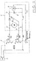
- Figure 1 shows the block diagram of an actuator 3, which is controlled by a control unit (ECU) 1, which is supplied with voltage from a battery 2.
- the actuator 3 has an electric motor 4 which actuates an actuating element (not shown here), the position or change in position of which is detected by a position sensor 9. The corresponding position or change in position is fed from the position sensor 9 in the form of electrical signals via a line 10 to the control unit 1.
- the electric motor 4 is supplied with pulsed voltage via the lines 5, 6 of the control unit 1.
- the supply of the motor 4 is also used to operate the position sensor 9 with electrical energy (direct voltage), so that separate supply lines for operating the sensor 9 can be omitted.
- a rectifier circuit with a series resistor 7 and a storage capacitor 8 is provided behind the tapping of the motor connections. Through this a filtered DC voltage is generated, which supplies the electronic position sensor 9 with sufficient voltage.
- the rectifier circuit has a bridge circuit 13 comprising diodes. It is provided here that at least one connection supplies a positive voltage at periodic intervals and that there is a common ground for the bridge circuit and signal evaluation.
- the connections of the control voltage U M1 and U M2 for operating the motor 4 are connected in such a way that at least one of the two motor connections U M1 , U M2 is connected to a positive voltage U B when the motor is idling and / or during an engine brake.
- the rectifier circuit comprises only one half bridge 12 with diodes.
- the embodiment of the Figure 1 thus represents an actuator feedback system without sensor supply lines in the form of a three-wire concept, while the embodiment of FIG Figure 2 shows such a system in the form of a four-wire concept. In all cases, there is no need for separate feed lines for applying the required supply voltage to the position sensor.
Description
Die vorliegende Erfindung betrifft einen Aktuator mit einem von einer Steuereinheit angesteuerten elektrischen Motor und einem aktiven elektronischen Positionssensor zur Erfassung der Aktuatorposition mit den Merkmalen des Oberbegriffs von Patentanspruch 1.The present invention relates to an actuator with an electric motor controlled by a control unit and an active electronic position sensor for detecting the actuator position with the features of the preamble of patent claim 1.
Aktuatoren werden für die verschiedensten Zwecke eingesetzt, beispielsweise zur Betätigung von Ventilen oder Klappen in Kraftfahrzeugen. Die hier angesprochenen Aktuatoren besitzen einen elektrischen Motor, der von einer Steuereinheit, beispielsweise einer Motorsteuerelektronik (ECU), angesteuert wird. Der elektrische Motor kann beispielsweise ein Betätigungselement betreiben, dessen Lageveränderung über ein Getriebe von einem Positionssensor erfasst wird. Zum Betreiben dieses Positionssensors wird eine Versorgungsspannung benötigt.Actuators are used for a wide variety of purposes, for example to operate valves or flaps in motor vehicles. The actuators discussed here have an electric motor that is controlled by a control unit, for example engine control electronics (ECU). The electric motor can, for example, operate an actuating element, the change in position of which is detected by a position sensor via a transmission. A supply voltage is required to operate this position sensor.
Aktive Positionssensoren für die Lageerfassung bzw. Lageregelung von Aktuatoren werden beim Stand der Technik mit separaten Zuleitungen mit elektrischer Energie (i. d. R. Spannung) versorgt. Es gibt dabei verschiedene Ausgangssignale für die Übertragung der Aktuatorposition. Die bekannte analoge Schnittstelle ist ratiometrisch zur Versorgungsspannung. Daher muss hierbei die Versorgungsspannung, die als Referenz in der Steuereinheit erzeugt wird, auch direkt mit dem Positionssensor verbunden werden. Anders verhält es sich bei versorgungsspannungsunabhängigen (nicht-ratiometrischen) Ausgangssignalen von Positionssensoren. Hier muss nicht zwangsläufig die Versorgungsspannung aus der Steuereinheit zugeführt werden, wenn der Sensor anders mit Energie versorgt werden kann. Nach wie vor besteht jedoch das Problem, dass eine vom Motor separate Versorgungsspannung, beispielsweise von 5 V, für die Positionssensoren über separate Zuleitungen zugeführt werden muss. Dies gilt auch für die neu eingeführte digitale Signalübertragung der Position, wo beispielsweise für eine Punkt-zu-Punkt-Verbindung (kein Bus) ein digitales serielles SENT-Protokoll verwendet wird.In the prior art, active position sensors for position detection or position control of actuators are supplied with electrical energy (usually voltage) with separate supply lines. There are different output signals for the transmission of the actuator position. The well-known analog interface is ratiometric to the supply voltage. Therefore, the supply voltage that is generated as a reference in the control unit must also be connected directly to the position sensor. The situation is different with voltage-independent (non-ratiometric) output signals from position sensors. Here, the supply voltage does not necessarily have to be supplied from the control unit if the sensor can be supplied with energy in another way. As before, however, there is the problem that a separate supply voltage from the motor, for example 5 V, for the position sensors via separate supply lines must be supplied. This also applies to the newly introduced digital signal transmission of the position, where a digital serial SENT protocol is used, for example, for a point-to-point connection (no bus).
Es versteht sich, dass die Anordnung von derartigen separaten Zuleitungen aufwändig ist.It goes without saying that the arrangement of such separate supply lines is complex.
Aus der
Ein weiteres Aktuatorsystem mit entsprechenden Merkmalen ist aus der
Aus der
Aus
Aus der
Die
Der Erfindung liegt die Aufgabe zugrunde, einen Aktuator der eingangs beschriebenen Art zur Verfügung zu stellen, der sich durch einen besonders einfachen Aufbau auszeichnet.The invention is based on the object of providing an actuator of the type described at the outset, which is distinguished by a particularly simple structure.
Diese Aufgabe wird erfindungsgemäß bei einem Aktuator der angegebenen Art durch die kennzeichnenden Merkmale von Patentanspruch 1 gelöst.According to the invention, this object is achieved with an actuator of the specified type by the characterizing features of patent claim 1.
Bei der erfindungsgemäßen Lösung entfallen separate Zuleitungen, über die der Positionssensor mit einer separaten Versorgungsspannung beaufschlagt wird. Stattdessen nutzt die Erfindung die ohnehin vorhandene Ansteuerleitung bzw. Versorgungsleitung des Motors von der vorgesehenen Steuereinheit auch für die Versorgung des Positionssensors mit elektrischer Energie. Zusätzliche Leitungen können daher entfallen.In the solution according to the invention, there is no need for separate supply lines via which the position sensor is subjected to a separate supply voltage. Instead, the invention uses the already existing control line or supply line of the motor from the control unit provided for supplying the position sensor with electrical energy. Additional lines can therefore be omitted.
Bei der erfindungsgemäßen Lösung ist vorgesehen, dass mindestens ein Motoranschluss in periodischen Abständen eine positive getaktete Spannung dadurch liefert, dass hinter dem Abgriff der Motoranschlüsse eine Gleichrichterschaltung mit Vorwiderstand und Speicherkondensator vorgesehen ist. Dabei sind die Anschlüsse der Ansteuerspannungen UM1 und UM2 für den Betrieb des Motors so geschaltet, dass während eines Motorleerlaufs (Anschlüsse UM1 und/oder UM2 sind über Transistoren hochohmig geschaltet) und/oder während einer Motorbremse (UM1 und UM2 sind auf gleiches Potenzial geschaltet → Kurzschluss zwischen UM1 und UM2) mindestens einer der beiden Motoranschlüsse UM1,UM2 mit einer positiven Spannung UB geschaltet ist.The solution according to the invention provides that at least one motor connection supplies a positive pulsed voltage at periodic intervals by providing a rectifier circuit with a series resistor and storage capacitor behind the tap of the motor connections. The connections of the control voltages U M1 and U M2 for the operation of the motor are connected in such a way that when the motor is idling (connections U M1 and / or U M2 are switched to high resistance via transistors) and / or during a motor brake (U M1 and U M2 are switched to the same potential → short circuit between U M1 and U M2 ) at least one of the two motor connections U M1 , U M2 is connected to a positive voltage U B.
Ferner ist in einer Ausgestaltung vorgesehen, dass eine gemeinsame Masse für eine Brückenschaltung der Motoransteuerung und Signalauswertung vorhanden ist.Furthermore, one embodiment provides that there is a common ground for a bridge circuit for motor control and signal evaluation.
Bei der erfindungsgemäßen Lösung bleiben die Ausgangssignale des Positionssensors innerhalb eines festgelegten Bereiches von der Versorgungsspannung unabhängig (nicht-ratiome-trisch.In the solution according to the invention, the output signals of the position sensor remain independent of the supply voltage within a defined range (non-ratiometric.
Besonders bevorzugt wird eine Ausführungsform, die dadurch gekennzeichnet ist, dass hinter dem Abgriff der Motoranschlüsse der Ansteuerleitung von der Steuereinheit eine Gleichrichterschaltung mit Speicherkondensator zur Erzeugung einer gefilterten Gleichspannung angeordnet ist, die den elektronischen Positionssensor mit einer ausreichenden Spannung versorgt. Hierbei kann auch ein Vorwiderstand vorgesehen sein.An embodiment is particularly preferred which is characterized in that a rectifier circuit with a storage capacitor for generating a filtered DC voltage is arranged behind the tap of the motor connections of the control line from the control unit, which supplies the electronic position sensor with sufficient voltage. A series resistor can also be provided here.
Die Gleichrichterschaltung kann hierbei eine Brückenschaltung umfassen.The rectifier circuit can include a bridge circuit.
Bei einer weiteren Ausführungsform ist eine separate Masseleitung zum Positionssensor geführt, wobei die Gleichrichterschaltung nur eine Halbbrücke aufweist.In a further embodiment, a separate ground line is routed to the position sensor, the rectifier circuit having only one half-bridge.
Ferner kann die Gleichrichterschaltung auch aus aktiven Transistoren bestehen. Hierbei ergibt sich ein kleinerer Spannungsabfall.Furthermore, the rectifier circuit can also consist of active transistors. This results in a smaller voltage drop.
Die Erfindung ist auch für einen bürstenlosen Motor mit zwei oder mehr Anschlüssen geeignet.The invention is also suitable for a brushless motor with two or more terminals.
Die Erfindung wird nachfolgend anhand von Ausführungsbeispielen in Verbindung mit der Zeichnung im Einzelnen erläutert. Es zeigen:
- Figur 1
- ein Blockschaltbild einer ersten Ausführungsform eines Aktuators mit Steuereinheit und Stromversorgung; und
Figur 2- ein Blockschaltbild einer zweiten Ausführungsform eines Aktuators mit Steuereinheit und Stromversorgung.
- Figure 1
- a block diagram of a first embodiment of an actuator with control unit and power supply; and
- Figure 2
- a block diagram of a second embodiment of an actuator with control unit and power supply.
Der elektrische Motor 4 wird über die Leitungen 5, 6 der Steuereinheit 1 mit getakteter Spannung beaufschlagt. Die Versorgung des Motors 4 wird ferner dazu benutzt, den Positionssensor 9 mit elektrischer Energie (Gleichspannung) zu betreiben, so dass separate Zuleitungen für den Betrieb des Sensors 9 entfallen können. Im Einzelnen ist dabei hinter dem Abgriff der Motoranschlüsse eine Gleichrichterschaltung mit Vorwiderstand 7 und Speicherkondensator 8 vorgesehen. Hierdurch wird eine gefilterte Gleichspannung erzeugt, die den elektronischen Positionssensor 9 mit einer ausreichenden Spannung versorgt.The electric motor 4 is supplied with pulsed voltage via the
Bei der in
Die in
Die Ausführungsform der
Claims (9)
- Actuator having an electric motor controlled by a control unit and having an active electronic position sensor for detecting the actuator position, wherein electrical energy for the operation of the position sensor is tapped from the control unit via the motor terminals of the motor control line, wherein the two motor terminals (5, 6) of the control voltage UM1 and UM2 for the operation of the motor (4) are switched such that at least one motor terminal (5, 6), at periodic intervals, delivers a positive pulsed voltage, characterized in that a rectifier circuit having a series resistor (7) and storage capacitor (8) is provided down-circuit of the motor terminal (5, 6) tap-off,
wherein, during the idling of the motor, one of the two motor terminals (5, 6) of the control voltage UM1 and UM2 carries a positive voltage UB and, during the braking of the motor, one of the two motor terminals (5, 6) of the control voltage UM1 and UM2 carries a positive voltage UB. - Actuator according to Claim 1, characterized in that a common ground potential is available for a bridge circuit of the motor control system and the signal evaluation system.
- Actuator according to Claim 1 or 2, characterized in that the output signals of the position sensor (9), within a specified range, remain independent of the supply voltage.
- Actuator according to one of the preceding claims, characterized in that, down-circuit of the motor terminal (5, 6) tap-off on the control line of the control unit (1), a rectifier circuit with a storage capacitor (8) for the generation of a filtered DC voltage is arranged, which delivers a sufficient voltage to the electronic position sensor (9).
- Actuator according to Claim 4, characterized in that a series resistor (7) is also provided.
- Actuator according to Claim 4 or 5, characterized in that the rectifier circuit comprises a bridge circuit (13).
- Actuator according to one of Claims 4 to 6, characterized in that a separate ground connection line (11) is routed to the position sensor (9), and in that the rectifier circuit is only provided with a half-bridge (12).
- Actuator according to one of Claims 4 to 7, characterized in that the rectifier circuit is comprised of active transistors.
- Actuator according to one of the preceding claims, characterized in that it is provided with a brushless motor with two or more terminals.
Applications Claiming Priority (2)
| Application Number | Priority Date | Filing Date | Title |
|---|---|---|---|
| DE102014212804.8A DE102014212804B4 (en) | 2014-07-02 | 2014-07-02 | Actuator with position sensor |
| PCT/EP2015/064956 WO2016001289A1 (en) | 2014-07-02 | 2015-07-01 | Actuator having a position sensor |
Publications (2)
| Publication Number | Publication Date |
|---|---|
| EP3078112A1 EP3078112A1 (en) | 2016-10-12 |
| EP3078112B1 true EP3078112B1 (en) | 2020-10-14 |
Family
ID=53499007
Family Applications (1)
| Application Number | Title | Priority Date | Filing Date |
|---|---|---|---|
| EP15733443.4A Active EP3078112B1 (en) | 2014-07-02 | 2015-07-01 | Actuator with position sensor |
Country Status (5)
| Country | Link |
|---|---|
| US (1) | US10630148B2 (en) |
| EP (1) | EP3078112B1 (en) |
| CN (1) | CN105940602B (en) |
| DE (1) | DE102014212804B4 (en) |
| WO (1) | WO2016001289A1 (en) |
Cited By (1)
| Publication number | Priority date | Publication date | Assignee | Title |
|---|---|---|---|---|
| DE102021111644A1 (en) | 2021-05-05 | 2022-11-10 | Schaeffler Technologies AG & Co. KG | Steering actuator and method for processing sensor signals |
Families Citing this family (4)
| Publication number | Priority date | Publication date | Assignee | Title |
|---|---|---|---|---|
| DE102014212804B4 (en) | 2014-07-02 | 2016-09-15 | Continental Automotive Gmbh | Actuator with position sensor |
| CN106783011B (en) * | 2016-12-27 | 2018-05-11 | 宁波市镇海华泰电器厂 | Using the alternating electromagnet of half-bridge circuit |
| CN106783012B (en) * | 2016-12-27 | 2018-06-19 | 宁波市镇海华泰电器厂 | The electromagnet of efficient electricity-saving |
| DE102017105543A1 (en) * | 2017-03-15 | 2018-09-20 | Schaeffler Technologies AG & Co. KG | Method and device for maintaining a detected absolute position of acting as an actuator electric motor in a critical operating case |
Citations (1)
| Publication number | Priority date | Publication date | Assignee | Title |
|---|---|---|---|---|
| EP2680431A2 (en) * | 2012-06-29 | 2014-01-01 | Melexis Technologies NV | Method and system for powering and measuring positions of a plurality of DC-motors over a wire interface |
Family Cites Families (14)
| Publication number | Priority date | Publication date | Assignee | Title |
|---|---|---|---|---|
| WO1994009240A1 (en) * | 1992-10-21 | 1994-04-28 | Robert Bosch Gmbh | Electromotive drive |
| ES2110555T3 (en) * | 1992-10-21 | 1998-02-16 | Bosch Gmbh Robert | DEVICE FOR THE DETECTION OF THE MOVEMENT OF A MOBILE PART. |
| US5389864A (en) * | 1993-03-29 | 1995-02-14 | Lake Center Industries, Inc. | Actuator with motor and feedback driven by a common power supply |
| JPH0775303A (en) * | 1993-07-09 | 1995-03-17 | Tamron Co Ltd | Actuator device and actuator |
| DE19527982C2 (en) * | 1995-07-31 | 2002-08-22 | Fhp Motors Gmbh | Electronically commutated electric motor |
| US6300736B1 (en) * | 1999-04-09 | 2001-10-09 | Melexis Nv | Low pin count DC-motor integrated drive circuit |
| DE19947698C2 (en) | 1999-10-04 | 2003-08-21 | Krohne Messtechnik Kg | gauge |
| US6545441B1 (en) * | 2002-08-21 | 2003-04-08 | Visteon Global Technologies, Inc. | Actuator for driving a driven member |
| US20050046366A1 (en) * | 2003-08-29 | 2005-03-03 | Johnson Controls Technology Company | Circuit for providing power to multiple electrical devices |
| CN1704766B (en) * | 2004-06-01 | 2010-05-05 | 安普生科技股份有限公司 | Hall integrated circuit with low working voltage and voltage regulator thereof |
| CN201142660Y (en) * | 2007-12-27 | 2008-10-29 | 保锐科技股份有限公司 | Motor control device |
| DE102008047494A1 (en) * | 2008-09-17 | 2010-04-15 | Continental Teves Ag & Co. Ohg | Electronically commutated direct current motor i.e. external rotor motor, for e.g. electronically controlled brake system in motor vehicle, has hall sensors that are supplied with electrical power via electrical power supply circuit |
| US9506955B2 (en) * | 2013-07-01 | 2016-11-29 | Apple Inc. | Polarity sensing circuit |
| DE102014212804B4 (en) | 2014-07-02 | 2016-09-15 | Continental Automotive Gmbh | Actuator with position sensor |
-
2014
- 2014-07-02 DE DE102014212804.8A patent/DE102014212804B4/en not_active Expired - Fee Related
-
2015
- 2015-07-01 US US15/115,960 patent/US10630148B2/en active Active
- 2015-07-01 WO PCT/EP2015/064956 patent/WO2016001289A1/en active Application Filing
- 2015-07-01 CN CN201580007204.0A patent/CN105940602B/en active Active
- 2015-07-01 EP EP15733443.4A patent/EP3078112B1/en active Active
Patent Citations (1)
| Publication number | Priority date | Publication date | Assignee | Title |
|---|---|---|---|---|
| EP2680431A2 (en) * | 2012-06-29 | 2014-01-01 | Melexis Technologies NV | Method and system for powering and measuring positions of a plurality of DC-motors over a wire interface |
Cited By (1)
| Publication number | Priority date | Publication date | Assignee | Title |
|---|---|---|---|---|
| DE102021111644A1 (en) | 2021-05-05 | 2022-11-10 | Schaeffler Technologies AG & Co. KG | Steering actuator and method for processing sensor signals |
Also Published As
| Publication number | Publication date |
|---|---|
| CN105940602B (en) | 2019-03-08 |
| DE102014212804A1 (en) | 2016-01-07 |
| EP3078112A1 (en) | 2016-10-12 |
| US20170163128A1 (en) | 2017-06-08 |
| CN105940602A (en) | 2016-09-14 |
| DE102014212804B4 (en) | 2016-09-15 |
| US10630148B2 (en) | 2020-04-21 |
| WO2016001289A1 (en) | 2016-01-07 |
Similar Documents
| Publication | Publication Date | Title |
|---|---|---|
| EP3078112B1 (en) | Actuator with position sensor | |
| DE102015106069A1 (en) | Electric motor drive device | |
| EP2460056B1 (en) | Method and device for monitoring a motion quantity on an electric drive in an error-proof manner | |
| DE102007026125B4 (en) | Control of an alternator for a motor vehicle | |
| EP4049510B1 (en) | Combined capacitive sensor and heating apparatus, method for operating a sensor and heating apparatus, steering input apparatus assembly having a sensor and heating apparatus, and vehicle having a steering input apparatus assembly | |
| DE102015220043A1 (en) | Control device for a rotary electric machine, and electric power steering device using this | |
| DE102019124293A1 (en) | Combined, capacitive sensor and heating device, method for operating a sensor and heating device, steering wheel assembly with a sensor and heating device and vehicle with a steering wheel assembly | |
| EP3188924B1 (en) | Method and device for monitoring an electric network in a rail vehicle and rail vehicle | |
| DE102009024572B4 (en) | Motor control device and motor control method | |
| EP3433134B1 (en) | Control device for a suspension component and suspension component for a vehicle | |
| EP3063505B1 (en) | Position sensor for detecting a position of an actuator | |
| WO2010086227A1 (en) | Method for operating a brushless motor | |
| DE102015005939B3 (en) | Method and system for operating an electrical interface | |
| EP3182607B1 (en) | Ventilator with status signal generation and status signal transfer through a supply line | |
| DE102015201543A1 (en) | Control method for standstill assurance of an electrical machine | |
| DE102014216384A1 (en) | Device and method for powering a sensor | |
| DE4413513A1 (en) | Controlling and monitoring electrical loads using microprocessor | |
| DE102014222665A1 (en) | Motor controller | |
| DE102014019119A1 (en) | Drive device for a motor vehicle | |
| EP3723238A1 (en) | Electrical installation | |
| DE102009007796B4 (en) | Method and device for supplying an electrically operated mechanical brake arranged in the vicinity of an electric motor | |
| DE10353741A1 (en) | Braking apparatus for rotor of electric motor e.g. in production machines and tools, supplies braking current via first switch to windings and diverts via second switch when braking process switched off | |
| DE102009007798A1 (en) | Method for supply of electrical load, involves providing electric power supply, by which secondary voltage is generated in motor current line additional to motor voltage | |
| DE102015223244A1 (en) | Apparatus and method for monitoring the speed of a vacuum pump drive | |
| DE102009003599B4 (en) | Circuit for speed control of an electric motor |
Legal Events
| Date | Code | Title | Description |
|---|---|---|---|
| PUAI | Public reference made under article 153(3) epc to a published international application that has entered the european phase |
Free format text: ORIGINAL CODE: 0009012 |
|
| 17P | Request for examination filed |
Effective date: 20160704 |
|
| AK | Designated contracting states |
Kind code of ref document: A1 Designated state(s): AL AT BE BG CH CY CZ DE DK EE ES FI FR GB GR HR HU IE IS IT LI LT LU LV MC MK MT NL NO PL PT RO RS SE SI SK SM TR |
|
| AX | Request for extension of the european patent |
Extension state: BA ME |
|
| DAV | Request for validation of the european patent (deleted) | ||
| DAX | Request for extension of the european patent (deleted) | ||
| STAA | Information on the status of an ep patent application or granted ep patent |
Free format text: STATUS: EXAMINATION IS IN PROGRESS |
|
| 17Q | First examination report despatched |
Effective date: 20190520 |
|
| RAP1 | Party data changed (applicant data changed or rights of an application transferred) |
Owner name: VITESCO TECHNOLOGIES GMBH |
|
| GRAP | Despatch of communication of intention to grant a patent |
Free format text: ORIGINAL CODE: EPIDOSNIGR1 |
|
| STAA | Information on the status of an ep patent application or granted ep patent |
Free format text: STATUS: GRANT OF PATENT IS INTENDED |
|
| INTG | Intention to grant announced |
Effective date: 20200609 |
|
| GRAS | Grant fee paid |
Free format text: ORIGINAL CODE: EPIDOSNIGR3 |
|
| GRAA | (expected) grant |
Free format text: ORIGINAL CODE: 0009210 |
|
| STAA | Information on the status of an ep patent application or granted ep patent |
Free format text: STATUS: THE PATENT HAS BEEN GRANTED |
|
| AK | Designated contracting states |
Kind code of ref document: B1 Designated state(s): AL AT BE BG CH CY CZ DE DK EE ES FI FR GB GR HR HU IE IS IT LI LT LU LV MC MK MT NL NO PL PT RO RS SE SI SK SM TR |
|
| REG | Reference to a national code |
Ref country code: GB Ref legal event code: FG4D Free format text: NOT ENGLISH |
|
| REG | Reference to a national code |
Ref country code: AT Ref legal event code: REF Ref document number: 1324549 Country of ref document: AT Kind code of ref document: T Effective date: 20201015 Ref country code: CH Ref legal event code: EP |
|
| REG | Reference to a national code |
Ref country code: DE Ref legal event code: R096 Ref document number: 502015013649 Country of ref document: DE |
|
| REG | Reference to a national code |
Ref country code: IE Ref legal event code: FG4D Free format text: LANGUAGE OF EP DOCUMENT: GERMAN |
|
| REG | Reference to a national code |
Ref country code: NL Ref legal event code: MP Effective date: 20201014 |
|
| PG25 | Lapsed in a contracting state [announced via postgrant information from national office to epo] |
Ref country code: RS Free format text: LAPSE BECAUSE OF FAILURE TO SUBMIT A TRANSLATION OF THE DESCRIPTION OR TO PAY THE FEE WITHIN THE PRESCRIBED TIME-LIMIT Effective date: 20201014 Ref country code: PT Free format text: LAPSE BECAUSE OF FAILURE TO SUBMIT A TRANSLATION OF THE DESCRIPTION OR TO PAY THE FEE WITHIN THE PRESCRIBED TIME-LIMIT Effective date: 20210215 Ref country code: FI Free format text: LAPSE BECAUSE OF FAILURE TO SUBMIT A TRANSLATION OF THE DESCRIPTION OR TO PAY THE FEE WITHIN THE PRESCRIBED TIME-LIMIT Effective date: 20201014 Ref country code: NO Free format text: LAPSE BECAUSE OF FAILURE TO SUBMIT A TRANSLATION OF THE DESCRIPTION OR TO PAY THE FEE WITHIN THE PRESCRIBED TIME-LIMIT Effective date: 20210114 Ref country code: NL Free format text: LAPSE BECAUSE OF FAILURE TO SUBMIT A TRANSLATION OF THE DESCRIPTION OR TO PAY THE FEE WITHIN THE PRESCRIBED TIME-LIMIT Effective date: 20201014 Ref country code: GR Free format text: LAPSE BECAUSE OF FAILURE TO SUBMIT A TRANSLATION OF THE DESCRIPTION OR TO PAY THE FEE WITHIN THE PRESCRIBED TIME-LIMIT Effective date: 20210115 |
|
| REG | Reference to a national code |
Ref country code: LT Ref legal event code: MG4D |
|
| PG25 | Lapsed in a contracting state [announced via postgrant information from national office to epo] |
Ref country code: LV Free format text: LAPSE BECAUSE OF FAILURE TO SUBMIT A TRANSLATION OF THE DESCRIPTION OR TO PAY THE FEE WITHIN THE PRESCRIBED TIME-LIMIT Effective date: 20201014 Ref country code: SE Free format text: LAPSE BECAUSE OF FAILURE TO SUBMIT A TRANSLATION OF THE DESCRIPTION OR TO PAY THE FEE WITHIN THE PRESCRIBED TIME-LIMIT Effective date: 20201014 Ref country code: PL Free format text: LAPSE BECAUSE OF FAILURE TO SUBMIT A TRANSLATION OF THE DESCRIPTION OR TO PAY THE FEE WITHIN THE PRESCRIBED TIME-LIMIT Effective date: 20201014 Ref country code: IS Free format text: LAPSE BECAUSE OF FAILURE TO SUBMIT A TRANSLATION OF THE DESCRIPTION OR TO PAY THE FEE WITHIN THE PRESCRIBED TIME-LIMIT Effective date: 20210214 Ref country code: BG Free format text: LAPSE BECAUSE OF FAILURE TO SUBMIT A TRANSLATION OF THE DESCRIPTION OR TO PAY THE FEE WITHIN THE PRESCRIBED TIME-LIMIT Effective date: 20210114 Ref country code: ES Free format text: LAPSE BECAUSE OF FAILURE TO SUBMIT A TRANSLATION OF THE DESCRIPTION OR TO PAY THE FEE WITHIN THE PRESCRIBED TIME-LIMIT Effective date: 20201014 |
|
| PG25 | Lapsed in a contracting state [announced via postgrant information from national office to epo] |
Ref country code: HR Free format text: LAPSE BECAUSE OF FAILURE TO SUBMIT A TRANSLATION OF THE DESCRIPTION OR TO PAY THE FEE WITHIN THE PRESCRIBED TIME-LIMIT Effective date: 20201014 |
|
| REG | Reference to a national code |
Ref country code: DE Ref legal event code: R097 Ref document number: 502015013649 Country of ref document: DE |
|
| PG25 | Lapsed in a contracting state [announced via postgrant information from national office to epo] |
Ref country code: LT Free format text: LAPSE BECAUSE OF FAILURE TO SUBMIT A TRANSLATION OF THE DESCRIPTION OR TO PAY THE FEE WITHIN THE PRESCRIBED TIME-LIMIT Effective date: 20201014 Ref country code: RO Free format text: LAPSE BECAUSE OF FAILURE TO SUBMIT A TRANSLATION OF THE DESCRIPTION OR TO PAY THE FEE WITHIN THE PRESCRIBED TIME-LIMIT Effective date: 20201014 Ref country code: SK Free format text: LAPSE BECAUSE OF FAILURE TO SUBMIT A TRANSLATION OF THE DESCRIPTION OR TO PAY THE FEE WITHIN THE PRESCRIBED TIME-LIMIT Effective date: 20201014 Ref country code: SM Free format text: LAPSE BECAUSE OF FAILURE TO SUBMIT A TRANSLATION OF THE DESCRIPTION OR TO PAY THE FEE WITHIN THE PRESCRIBED TIME-LIMIT Effective date: 20201014 Ref country code: CZ Free format text: LAPSE BECAUSE OF FAILURE TO SUBMIT A TRANSLATION OF THE DESCRIPTION OR TO PAY THE FEE WITHIN THE PRESCRIBED TIME-LIMIT Effective date: 20201014 Ref country code: EE Free format text: LAPSE BECAUSE OF FAILURE TO SUBMIT A TRANSLATION OF THE DESCRIPTION OR TO PAY THE FEE WITHIN THE PRESCRIBED TIME-LIMIT Effective date: 20201014 |
|
| PLBE | No opposition filed within time limit |
Free format text: ORIGINAL CODE: 0009261 |
|
| STAA | Information on the status of an ep patent application or granted ep patent |
Free format text: STATUS: NO OPPOSITION FILED WITHIN TIME LIMIT |
|
| PG25 | Lapsed in a contracting state [announced via postgrant information from national office to epo] |
Ref country code: DK Free format text: LAPSE BECAUSE OF FAILURE TO SUBMIT A TRANSLATION OF THE DESCRIPTION OR TO PAY THE FEE WITHIN THE PRESCRIBED TIME-LIMIT Effective date: 20201014 |
|
| 26N | No opposition filed |
Effective date: 20210715 |
|
| PG25 | Lapsed in a contracting state [announced via postgrant information from national office to epo] |
Ref country code: IT Free format text: LAPSE BECAUSE OF FAILURE TO SUBMIT A TRANSLATION OF THE DESCRIPTION OR TO PAY THE FEE WITHIN THE PRESCRIBED TIME-LIMIT Effective date: 20201014 Ref country code: AL Free format text: LAPSE BECAUSE OF FAILURE TO SUBMIT A TRANSLATION OF THE DESCRIPTION OR TO PAY THE FEE WITHIN THE PRESCRIBED TIME-LIMIT Effective date: 20201014 |
|
| PG25 | Lapsed in a contracting state [announced via postgrant information from national office to epo] |
Ref country code: SI Free format text: LAPSE BECAUSE OF FAILURE TO SUBMIT A TRANSLATION OF THE DESCRIPTION OR TO PAY THE FEE WITHIN THE PRESCRIBED TIME-LIMIT Effective date: 20201014 |
|
| REG | Reference to a national code |
Ref country code: DE Ref legal event code: R081 Ref document number: 502015013649 Country of ref document: DE Owner name: VITESCO TECHNOLOGIES GMBH, DE Free format text: FORMER OWNER: VITESCO TECHNOLOGIES GMBH, 30165 HANNOVER, DE |
|
| REG | Reference to a national code |
Ref country code: CH Ref legal event code: PL |
|
| GBPC | Gb: european patent ceased through non-payment of renewal fee |
Effective date: 20210701 |
|
| PG25 | Lapsed in a contracting state [announced via postgrant information from national office to epo] |
Ref country code: MC Free format text: LAPSE BECAUSE OF FAILURE TO SUBMIT A TRANSLATION OF THE DESCRIPTION OR TO PAY THE FEE WITHIN THE PRESCRIBED TIME-LIMIT Effective date: 20201014 |
|
| REG | Reference to a national code |
Ref country code: BE Ref legal event code: MM Effective date: 20210731 |
|
| PG25 | Lapsed in a contracting state [announced via postgrant information from national office to epo] |
Ref country code: LI Free format text: LAPSE BECAUSE OF NON-PAYMENT OF DUE FEES Effective date: 20210731 Ref country code: GB Free format text: LAPSE BECAUSE OF NON-PAYMENT OF DUE FEES Effective date: 20210701 Ref country code: CH Free format text: LAPSE BECAUSE OF NON-PAYMENT OF DUE FEES Effective date: 20210731 |
|
| PG25 | Lapsed in a contracting state [announced via postgrant information from national office to epo] |
Ref country code: IS Free format text: LAPSE BECAUSE OF FAILURE TO SUBMIT A TRANSLATION OF THE DESCRIPTION OR TO PAY THE FEE WITHIN THE PRESCRIBED TIME-LIMIT Effective date: 20210214 Ref country code: LU Free format text: LAPSE BECAUSE OF NON-PAYMENT OF DUE FEES Effective date: 20210701 |
|
| PG25 | Lapsed in a contracting state [announced via postgrant information from national office to epo] |
Ref country code: IE Free format text: LAPSE BECAUSE OF NON-PAYMENT OF DUE FEES Effective date: 20210701 Ref country code: BE Free format text: LAPSE BECAUSE OF NON-PAYMENT OF DUE FEES Effective date: 20210731 |
|
| REG | Reference to a national code |
Ref country code: AT Ref legal event code: MM01 Ref document number: 1324549 Country of ref document: AT Kind code of ref document: T Effective date: 20210701 |
|
| PG25 | Lapsed in a contracting state [announced via postgrant information from national office to epo] |
Ref country code: AT Free format text: LAPSE BECAUSE OF NON-PAYMENT OF DUE FEES Effective date: 20210701 |
|
| PG25 | Lapsed in a contracting state [announced via postgrant information from national office to epo] |
Ref country code: HU Free format text: LAPSE BECAUSE OF FAILURE TO SUBMIT A TRANSLATION OF THE DESCRIPTION OR TO PAY THE FEE WITHIN THE PRESCRIBED TIME-LIMIT; INVALID AB INITIO Effective date: 20150701 |
|
| PG25 | Lapsed in a contracting state [announced via postgrant information from national office to epo] |
Ref country code: CY Free format text: LAPSE BECAUSE OF FAILURE TO SUBMIT A TRANSLATION OF THE DESCRIPTION OR TO PAY THE FEE WITHIN THE PRESCRIBED TIME-LIMIT Effective date: 20201014 |
|
| P01 | Opt-out of the competence of the unified patent court (upc) registered |
Effective date: 20230530 |
|
| PGFP | Annual fee paid to national office [announced via postgrant information from national office to epo] |
Ref country code: FR Payment date: 20230726 Year of fee payment: 9 Ref country code: DE Payment date: 20230731 Year of fee payment: 9 |