EP2955432A2 - Dispositif d'eclairage pour vehicules - Google Patents
Dispositif d'eclairage pour vehicules Download PDFInfo
- Publication number
- EP2955432A2 EP2955432A2 EP15171347.6A EP15171347A EP2955432A2 EP 2955432 A2 EP2955432 A2 EP 2955432A2 EP 15171347 A EP15171347 A EP 15171347A EP 2955432 A2 EP2955432 A2 EP 2955432A2
- Authority
- EP
- European Patent Office
- Prior art keywords
- light
- boundary surface
- reflection structure
- light guide
- lighting device
- Prior art date
- Legal status (The legal status is an assumption and is not a legal conclusion. Google has not performed a legal analysis and makes no representation as to the accuracy of the status listed.)
- Granted
Links
Images

Classifications
-
- G—PHYSICS
- G02—OPTICS
- G02B—OPTICAL ELEMENTS, SYSTEMS OR APPARATUS
- G02B6/00—Light guides; Structural details of arrangements comprising light guides and other optical elements, e.g. couplings
- G02B6/0001—Light guides; Structural details of arrangements comprising light guides and other optical elements, e.g. couplings specially adapted for lighting devices or systems
- G02B6/0005—Light guides; Structural details of arrangements comprising light guides and other optical elements, e.g. couplings specially adapted for lighting devices or systems the light guides being of the fibre type
- G02B6/001—Light guides; Structural details of arrangements comprising light guides and other optical elements, e.g. couplings specially adapted for lighting devices or systems the light guides being of the fibre type the light being emitted along at least a portion of the lateral surface of the fibre
-
- B—PERFORMING OPERATIONS; TRANSPORTING
- B60—VEHICLES IN GENERAL
- B60Q—ARRANGEMENT OF SIGNALLING OR LIGHTING DEVICES, THE MOUNTING OR SUPPORTING THEREOF OR CIRCUITS THEREFOR, FOR VEHICLES IN GENERAL
- B60Q1/00—Arrangement of optical signalling or lighting devices, the mounting or supporting thereof or circuits therefor
- B60Q1/0029—Spatial arrangement
- B60Q1/0041—Spatial arrangement of several lamps in relation to each other
- B60Q1/0052—Spatial arrangement of several lamps in relation to each other concentric
-
- F—MECHANICAL ENGINEERING; LIGHTING; HEATING; WEAPONS; BLASTING
- F21—LIGHTING
- F21S—NON-PORTABLE LIGHTING DEVICES; SYSTEMS THEREOF; VEHICLE LIGHTING DEVICES SPECIALLY ADAPTED FOR VEHICLE EXTERIORS
- F21S43/00—Signalling devices specially adapted for vehicle exteriors, e.g. brake lamps, direction indicator lights or reversing lights
- F21S43/20—Signalling devices specially adapted for vehicle exteriors, e.g. brake lamps, direction indicator lights or reversing lights characterised by refractors, transparent cover plates, light guides or filters
- F21S43/235—Light guides
- F21S43/236—Light guides characterised by the shape of the light guide
- F21S43/237—Light guides characterised by the shape of the light guide rod-shaped
-
- F—MECHANICAL ENGINEERING; LIGHTING; HEATING; WEAPONS; BLASTING
- F21—LIGHTING
- F21S—NON-PORTABLE LIGHTING DEVICES; SYSTEMS THEREOF; VEHICLE LIGHTING DEVICES SPECIALLY ADAPTED FOR VEHICLE EXTERIORS
- F21S43/00—Signalling devices specially adapted for vehicle exteriors, e.g. brake lamps, direction indicator lights or reversing lights
- F21S43/20—Signalling devices specially adapted for vehicle exteriors, e.g. brake lamps, direction indicator lights or reversing lights characterised by refractors, transparent cover plates, light guides or filters
- F21S43/235—Light guides
- F21S43/236—Light guides characterised by the shape of the light guide
- F21S43/241—Light guides characterised by the shape of the light guide of complex shape
-
- F—MECHANICAL ENGINEERING; LIGHTING; HEATING; WEAPONS; BLASTING
- F21—LIGHTING
- F21S—NON-PORTABLE LIGHTING DEVICES; SYSTEMS THEREOF; VEHICLE LIGHTING DEVICES SPECIALLY ADAPTED FOR VEHICLE EXTERIORS
- F21S43/00—Signalling devices specially adapted for vehicle exteriors, e.g. brake lamps, direction indicator lights or reversing lights
- F21S43/20—Signalling devices specially adapted for vehicle exteriors, e.g. brake lamps, direction indicator lights or reversing lights characterised by refractors, transparent cover plates, light guides or filters
- F21S43/235—Light guides
- F21S43/242—Light guides characterised by the emission area
- F21S43/245—Light guides characterised by the emission area emitting light from one or more of its major surfaces
-
- F—MECHANICAL ENGINEERING; LIGHTING; HEATING; WEAPONS; BLASTING
- F21—LIGHTING
- F21S—NON-PORTABLE LIGHTING DEVICES; SYSTEMS THEREOF; VEHICLE LIGHTING DEVICES SPECIALLY ADAPTED FOR VEHICLE EXTERIORS
- F21S43/00—Signalling devices specially adapted for vehicle exteriors, e.g. brake lamps, direction indicator lights or reversing lights
- F21S43/20—Signalling devices specially adapted for vehicle exteriors, e.g. brake lamps, direction indicator lights or reversing lights characterised by refractors, transparent cover plates, light guides or filters
- F21S43/235—Light guides
- F21S43/251—Light guides the light guides being used to transmit light from remote light sources
-
- G—PHYSICS
- G02—OPTICS
- G02B—OPTICAL ELEMENTS, SYSTEMS OR APPARATUS
- G02B6/00—Light guides; Structural details of arrangements comprising light guides and other optical elements, e.g. couplings
- G02B6/0001—Light guides; Structural details of arrangements comprising light guides and other optical elements, e.g. couplings specially adapted for lighting devices or systems
- G02B6/0011—Light guides; Structural details of arrangements comprising light guides and other optical elements, e.g. couplings specially adapted for lighting devices or systems the light guides being planar or of plate-like form
- G02B6/0033—Means for improving the coupling-out of light from the light guide
- G02B6/0063—Means for improving the coupling-out of light from the light guide for extracting light out both the major surfaces of the light guide
-
- G—PHYSICS
- G02—OPTICS
- G02B—OPTICAL ELEMENTS, SYSTEMS OR APPARATUS
- G02B6/00—Light guides; Structural details of arrangements comprising light guides and other optical elements, e.g. couplings
- G02B6/0001—Light guides; Structural details of arrangements comprising light guides and other optical elements, e.g. couplings specially adapted for lighting devices or systems
- G02B6/0011—Light guides; Structural details of arrangements comprising light guides and other optical elements, e.g. couplings specially adapted for lighting devices or systems the light guides being planar or of plate-like form
- G02B6/0013—Means for improving the coupling-in of light from the light source into the light guide
- G02B6/0015—Means for improving the coupling-in of light from the light source into the light guide provided on the surface of the light guide or in the bulk of it
- G02B6/0018—Redirecting means on the surface of the light guide
-
- G—PHYSICS
- G02—OPTICS
- G02B—OPTICAL ELEMENTS, SYSTEMS OR APPARATUS
- G02B6/00—Light guides; Structural details of arrangements comprising light guides and other optical elements, e.g. couplings
- G02B6/0001—Light guides; Structural details of arrangements comprising light guides and other optical elements, e.g. couplings specially adapted for lighting devices or systems
- G02B6/0011—Light guides; Structural details of arrangements comprising light guides and other optical elements, e.g. couplings specially adapted for lighting devices or systems the light guides being planar or of plate-like form
- G02B6/0013—Means for improving the coupling-in of light from the light source into the light guide
- G02B6/0023—Means for improving the coupling-in of light from the light source into the light guide provided by one optical element, or plurality thereof, placed between the light guide and the light source, or around the light source
- G02B6/0028—Light guide, e.g. taper
-
- G—PHYSICS
- G02—OPTICS
- G02B—OPTICAL ELEMENTS, SYSTEMS OR APPARATUS
- G02B6/00—Light guides; Structural details of arrangements comprising light guides and other optical elements, e.g. couplings
- G02B6/0001—Light guides; Structural details of arrangements comprising light guides and other optical elements, e.g. couplings specially adapted for lighting devices or systems
- G02B6/0011—Light guides; Structural details of arrangements comprising light guides and other optical elements, e.g. couplings specially adapted for lighting devices or systems the light guides being planar or of plate-like form
- G02B6/0033—Means for improving the coupling-out of light from the light guide
- G02B6/0035—Means for improving the coupling-out of light from the light guide provided on the surface of the light guide or in the bulk of it
- G02B6/0038—Linear indentations or grooves, e.g. arc-shaped grooves or meandering grooves, extending over the full length or width of the light guide
-
- G—PHYSICS
- G02—OPTICS
- G02B—OPTICAL ELEMENTS, SYSTEMS OR APPARATUS
- G02B6/00—Light guides; Structural details of arrangements comprising light guides and other optical elements, e.g. couplings
- G02B6/0001—Light guides; Structural details of arrangements comprising light guides and other optical elements, e.g. couplings specially adapted for lighting devices or systems
- G02B6/0011—Light guides; Structural details of arrangements comprising light guides and other optical elements, e.g. couplings specially adapted for lighting devices or systems the light guides being planar or of plate-like form
- G02B6/0033—Means for improving the coupling-out of light from the light guide
- G02B6/0058—Means for improving the coupling-out of light from the light guide varying in density, size, shape or depth along the light guide
- G02B6/0061—Means for improving the coupling-out of light from the light guide varying in density, size, shape or depth along the light guide to provide homogeneous light output intensity
Definitions
- the invention relates to a lighting device for vehicles, in particular motor vehicles, comprising at least one light source and at least one light guide arrangement assigned to the at least one light source for guiding the light emitted by the at least one light source and coupled into the light guide arrangement, wherein one or more light guides in the light guide arrangement, wherein the at least one optical fiber has one or more coupling points for decoupling at least a portion of the coupled-in light, and wherein the at least one optical fiber for deflecting the light towards the at least one decoupling point at least partially at one of the at least one outcoupling point opposite boundary surface of the optical fiber has a reflection structure , wherein the reflection structure comprises a number of reflection structure elements, which reflection structure elements as inward, in the light guide ger Recesses are formed, which are arranged and / or formed such that at least a portion of the luminous flux, preferably the entire luminous flux, which is totally reflected on a structure element surface which limits the reflection structure element, on the structure element surface.
- the invention relates to a vehicle headlight, in particular motor vehicle headlight with at least one such lighting device.
- the invention relates to a vehicle, in particular a motor vehicle with at least one such vehicle headlight.
- At least one, preferably exactly one, optical element for example at least one thick-wall optical system is then provided on at least one light-exit-side boundary surface, into which light is coupled via the at least light-out coupling of the optical waveguide, which light at least a light exit surface of the at least one optical element emerges to form a light function and / or a light distribution.
- the reflection structure comprises coupling-out means for decoupling at least part of the light incident on the reflection structure, preferably incident between the reflection structure elements, in a direction away from the at least one coupling-out location.
- direction away from the point of decoupling means that a vector component of a considered light beam is directed counter to the main decoupling direction.
- the reflection structure elements are arranged one behind the other in a main light-guiding direction and adjacent reflection structure elements are arranged at a distance from one another.
- the main light-guiding direction corresponds to the main light-deflecting direction (s).
- the coupling-out means comprise elevations or are formed as elevations, which elevations on the reflection surface having the boundary surface of the light guide, in areas between adjacent reflection structure elements, of the Boundary surface to the outside, from the at least one output point pioneering, are arranged.
- elevations for example in the form of prisms on the back of the light guide, preferably in the vicinity of the deflection, the total reflection is suppressed, so that the disturbing light impression is prevented in oblique viewing.
- the elevations are, for example, staircase-shaped on the back of the light guide applied (or integrally formed with this) additional surfaces and allow leakage of unwanted light rays to the rear.
- the elevations are configured and / or arranged such that at least a portion of the light which impinges on a elevation boundary surface, which elevation boundary surface in each case delimits an elevation to the outside, exits the light guide via the elevation boundary surface.
- light guides and elevations are made of the same material, in particular, these are preferably produced in one piece.
- the elevations have a prismatic shape or are formed as prisms.
- the elevation boundary surfaces each consist of two boundary subareas, which converge in a survey edge.
- elevation edges may be due to manufacturing technology, e.g. when manufactured by means of an injection process, have slight edge rounding.
- At least one, preferably both limiting partial surfaces are formed as flat surfaces.
- elevations preferably all elevations, extend in each case over the entire area between two reflection structure elements.
- elevations preferably all elevations each extend over substantially the entire height extent of at least one adjacent structural element.
- the local angle between the elevation boundary surface and the original boundary surface of the light guide is less than the angle in a rear region of the elevation boundary surface.
- Each land boundary surface has a “dot” (in fact generally a curve with dots) with maximum distance to the original light pipe boundary surface - this "point” or curve divides the land boundary surface into a front area and a rear area.
- "Rear” and “Front” can be seen in relation to the main guide direction, i. the front region faces the deflection device, the rear region faces away from the deflection device.
- “Local” angle means that with a curved elevation, the angle changes along the elevation boundary surface.
- Local is meant the angle of a tangential plane at a point of interest to the elevation boundary surface.
- each sub-area has exactly one angle, which is preferably measured between the sub-area and a tangent plane to the light guide in the region of the intersection or the interface of the sub-area with the back of the light guide.
- the relation "rear area rear partial area”
- the local angle between the elevation boundary surface and the original boundary surface of the light guide is such it is selected that at least a part of the light incident on the rear area of the elevation boundary surface exits the light guide via the rear area of the elevation boundary surface.
- the local angle between the elevation boundary surface and the original boundary surface of the light guide is selected such that at least a portion of the area at the rear of the elevation area is selected. Impact surface incident light impinges at an angle which is smaller than the limit angle for total reflection in the considered, local point of the survey boundary surface.
- the front partial surface occupies a first angle to the original boundary surface, which is preferably in a range of 12.5 ° - 40 ° and / or the rear Partial surface occupies a second angle to the original boundary surface, which is preferably in a range of 70 ° - 90 °.
- the reflection structure elements have a prismatic shape or are formed as prisms.
- the reflection structure element boundary surfaces each consist of two boundary sub-areas, which converge in one structure element edge.
- At least one, or preferably both reflective structure element partial surfaces are formed as flat surfaces.
- the local angle between the reflection structure element boundary surface and the original boundary surface of the light guide is selected such that at least a part, preferably substantially all of them Reflected area light flux is totally reflected and deflected to at least one Lichtauskoppelstelle.
- the angle to the original boundary surface is in a range of 40 ° -45 °.
- edges of the reflection structure elements and the elevations run parallel to one another.
- the reflection structure elements in particular the edges of the reflection structure elements are arranged equidistantly.
- the height of the reflection structure elements i. the normal distance of the edges of the reflection structure elements to the original boundary surface increases as it progresses along the light guide.
- the height of the elevations i. the normal distance of the edges of the elevations to the original boundary surface, decreases as it progresses along the light guide.
- the height of the elevations decreases to the same extent as the height of the reflection structure elements increases.
- At least one, preferably exactly one optical element for example at least one thick-wall optical system, is then provided on at least one light-exit-side boundary surface into which light is coupled via the at least light coupling-out point of the optical waveguide arrangement Light exits at least one light exit surface of the at least one optical element to form a light function and / or a light distribution.
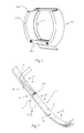
- FIG. 1 shows a lighting device 10 for vehicles, in particular motor vehicles, which at least one light source (not shown) and one of the at least one light source, not shown here in detail light guide assembly 1 for guiding the radiated from the at least one light source and coupled into the light guide assembly 1 comprises light
- the optical waveguide arrangement has, for example, an optical waveguide into which light from the light source is fed via a light-coupling region.
- a light deflection device for example a deflection prism
- the invention is not limited to such a variant.
- an optical element 200 for example, a thick-wall optics is provided, in which light via the light extraction point of the light guide assembly 1 and the light guide is coupled. This light is emitted at a light exit surface 210 of the optical element 200 to form a light function and / or a light distribution.
- lateral illumination spots 300 are formed on the light exit surface 210 of the optical element 200.
- a light guide arrangement according to the invention or a light guide according to the invention is used as described below.
- FIG. 2 shows a light guide assembly 1 according to the invention with a light guide 4, in which via a feed line 3 light from at least one, not shown, light source in the light feed direction L1 is fed.
- a deflecting device 100 is schematically indicated, by means of which, in the shown, non-limiting embodiment, the injected light is fed into both arms of the optical fiber 4.
- the light guide 4 has extraction points 2 for decoupling at least part of the coupled-in light.
- the extraction points are essentially the entire front side 2 of the light guide, from which light can emerge and is emitted into a region in front of the illumination device or in front of the vehicle.
- the reflection structure 5 For deflecting the light to the front side (coupling-out region, coupling-out points) 2 of the optical waveguide, it has a reflection structure 5 on the opposite boundary surface 40 (also referred to below as backside), the reflection structure 5 comprising a number of reflection structure elements 5a, which comprise reflection structure elements 5a inside, in the light guide 4 into (ie in the direction of the front side 2) directed depressions are formed.
- These reflection structure elements 5a are arranged and / or formed such that at least part of the luminous flux, preferably the total luminous flux, which is totally reflected on a structure element surface 5b, 5c which delimits the reflection structure element 5, is totally reflected on the structure element surface 5b, 5c ,
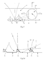
- FIG. 3 shows a known from the prior art light guide 4, which has such reflection structure elements 5a
- FIG. 3a shows these reflection structure elements 5a in detail.
- Light which is coupled into the light guide 4 in the direction L1 (main light-receiving direction) and deflected in the two directions L2 (main light-guiding directions L2) is totally reflected and stepped on the back surface 40 and on the reflecting structure elements 5a of the light guide 4 as shown via the front side 2 from the light guide 4.
- the main light guide direction of the (or the) is also referred to as the main Lichtumlenkraum (en) L2.
- a reflecting structure element 5a is preferably formed, as shown, by two structural element surfaces 5b, 5c which, as shown, are preferably flat and converge in an edge 5d.
- Light, which impinges directly on the front surface 5b, is reflected by this to the front side 2, light, which impinges on the back 40 of the light guide 4 between two reflection structure elements 5a, is also totally reflected there and, optionally after further reflection on the surface 5b, emitted to the front.
- Light is emitted via the front side 2 in the direction of the main light output direction L3, which is generally parallel to the direction of travel of the vehicle in which the lighting device is arranged, and is imaged in an area in front of the vehicle.
- the reflection structure 5 additionally comprises, in addition to the reflection structure elements 5a, outcoupling means 20 for decoupling at least a portion of the light incident on the reflection structure 5 between the reflection structure elements 5 in a direction away from the decoupling point 2.
- FIG. 4a shows in detail this coupling-out means, and as can be seen, the light beam (shown in FIG. 3a was still totally reflected) not totally reflected and exits backwards out of the light guide, so it can no longer contribute to the formation of an unwanted luminance spots.
- the reflection structure elements 5a are arranged one behind the other in a main light-guiding direction L2 and adjacent reflection structure elements 5a are arranged at a distance from one another.
- the reflection structure elements 5a have a prismatic shape or are formed as prisms.
- the reflective feature element boundary surfaces are as related to Figures 3 and 3a already mentioned in each case from two planar boundary partial surfaces 5b, 5c, which converge in a structural element edge 5d.
- the (local) angle 50b between the front planar reflecting structure element delimiting surface 5b and the original limiting surface 40 of the optical waveguide 4 is selected such that at least a part, preferably substantially all, of the luminous flux incident on this region 5b is totally reflected and directed to the light extraction point (front side). 2 is deflected.
- this angle is 50b to the original boundary surface 40 in a range of 40 ° - 45 °.
- the angle 50c of the rear reflective feature limiting surface 5c is larger than the front angle 50b as shown.
- the reflection structure elements 5a in particular the edges 5d of the reflection structure elements 5a are arranged equidistantly. It is also favorable if the height of the reflection structure elements 5a, i. the normal distance of the edges 5d of the reflection structure elements 5a to the original boundary surface 40 increases as it progresses along the light guide. The "progression" begins at the Lichteinkoppel Anlagen and takes place in the light guide.
- the coupling-out means comprise a number of elevations 20, which elevations 20 are arranged on the limiting surface 40 of the light guide 4 having the reflection structure 5, in regions between adjacent reflection structure elements 5, pointing away from the limiting surface 40 to the outside, away from the extraction point 2.
- Such an elevation 20 is in each case located between two reflection structure elements 5 a, wherein an elevation 20 preferably occupies substantially the entire area between the two structural elements 5 a.
- the elevations 20 are configured and / or arranged such that at least part of the light which impinges on an elevation delimiting surface 20a, 20b, which elevation delimiting surface 20a, 20b in each case delimits an elevation 20 toward the outside, projects beyond the elevation area.
- the elevations 20 preferably have a prismatic shape or are formed as prisms. Specifically, in the embodiment shown, the elevations 20 are respectively bounded by two flat boundary partial surfaces 20a, 20b, which converge in a raised edge 20c. These elevation edges may be due to manufacturing technology, e.g. when manufactured by means of an injection process, have slight edge rounding.
- elevations 20, preferably all elevations 20 each extend over substantially the entire height extent of the adjacent structural elements 5 extend.
- the term "height extension” is the extent of the reflection structure elements transverse to a main light-guiding direction, that is to say the direction normal to the plane of the drawing in FIG 4, 4a to understand.
- the angle 120a between a bump boundary surface 20a and the original boundary surface 40 of the light guide 4 is preferably less than the angle 120b between the rear bump boundary surface 20b, as shown.
- the angle (120b) between the rear bump boundary surface 20b and the original boundary surface 40 is selected so that at least part of the light incident on the rear portion of the bump boundary surface 20b exits the light guide 4 via the rear bump boundary surface 20b ,
- the angle 120b is preferably selected such that at least a portion of the light incident on the rear of the bump boundary surface 20b impinges at an angle on the bump boundary surface 20b, which is less than the limit angle for total reflection in the localized one Point of the land boundary surface 20b.
- the angle 120a between a front partial surface 20a and the original limiting surface 40 is in a range of 12.5 ° -40 °
- the second, "rear" angle 120b is preferably in a range of 70 ° -90 °.
- edges 5d of the reflection structure elements 5 and the edges 20c of the elevations 20 preferably run parallel to one another.
- the height of the elevations 20, i. the normal distance of the edges 20c of the projections 20 to the original boundary surface 40 decreases as it progresses along the optical fiber.
- the height of the elevations 20 preferably decreases to the same extent as the height of the reflection structure elements 5a increases.
Landscapes
- Engineering & Computer Science (AREA)
- General Engineering & Computer Science (AREA)
- Physics & Mathematics (AREA)
- General Physics & Mathematics (AREA)
- Optics & Photonics (AREA)
- Mechanical Engineering (AREA)
- Planar Illumination Modules (AREA)
- Non-Portable Lighting Devices Or Systems Thereof (AREA)
Applications Claiming Priority (1)
| Application Number | Priority Date | Filing Date | Title |
|---|---|---|---|
| ATA50401/2014A AT515864B1 (de) | 2014-06-11 | 2014-06-11 | Beleuchtungsvorrichtung für Fahrzeuge sowie Kraftfahrzeugscheinwerfer |
Publications (3)
| Publication Number | Publication Date |
|---|---|
| EP2955432A2 true EP2955432A2 (fr) | 2015-12-16 |
| EP2955432A3 EP2955432A3 (fr) | 2016-01-27 |
| EP2955432B1 EP2955432B1 (fr) | 2021-08-04 |
Family
ID=53442510
Family Applications (1)
| Application Number | Title | Priority Date | Filing Date |
|---|---|---|---|
| EP15171347.6A Active EP2955432B1 (fr) | 2014-06-11 | 2015-06-10 | Dispositif d'eclairage pour vehicules |
Country Status (3)
| Country | Link |
|---|---|
| EP (1) | EP2955432B1 (fr) |
| CN (1) | CN105299558B (fr) |
| AT (1) | AT515864B1 (fr) |
Cited By (7)
| Publication number | Priority date | Publication date | Assignee | Title |
|---|---|---|---|---|
| WO2017215987A1 (fr) * | 2016-06-16 | 2017-12-21 | Philips Lighting Holding B.V. | Système d'éclairage utilisant une structure de guidage de lumière |
| DE102017102237A1 (de) | 2017-02-06 | 2018-08-09 | HELLA GmbH & Co. KGaA | Beleuchtungsvorrichtung für ein Kraftfahrzeug |
| US10073205B1 (en) | 2017-05-05 | 2018-09-11 | Maxzone Vehicle Lighting Corp. | Optical module of vehicle light and light guide |
| CN110187435A (zh) * | 2019-05-30 | 2019-08-30 | 山东光韵智能科技有限公司 | 一种远距离照明用多节点光纤及其制造方法 |
| CZ307956B6 (cs) * | 2018-06-25 | 2019-09-11 | Varroc Lighting Systems, s.r.o. | Světlovodivý optický systém, zejména pro motorová vozidla |
| CN114719223A (zh) * | 2022-02-21 | 2022-07-08 | 岚图汽车科技有限公司 | 一种信号灯和机动车 |
| EP4368880A1 (fr) * | 2022-11-08 | 2024-05-15 | Hella Autotechnik Nova, s.r.o. | Guide de lumière pour lampe de véhicule automobile |
Families Citing this family (5)
| Publication number | Priority date | Publication date | Assignee | Title |
|---|---|---|---|---|
| DE102016115278B4 (de) | 2016-08-17 | 2023-11-02 | Automotive Lighting Reutlingen Gmbh | Beleuchtungseinrichtung für ein Kraftfahrzeug |
| CN108916805B (zh) * | 2017-03-22 | 2021-03-30 | 堤维西交通工业股份有限公司 | 车灯透镜 |
| CN110953547B (zh) * | 2019-12-10 | 2022-08-12 | 东风汽车有限公司 | 用于车灯的厚壁件及车灯 |
| CN112594650A (zh) * | 2020-12-16 | 2021-04-02 | 领为视觉智能科技(宁波)有限公司 | 一种利用光栅全反射的厚壁件及其应用 |
| CN112902105B (zh) * | 2021-03-25 | 2022-09-30 | 兰普电器股份有限公司 | 异型侧反射前照灯 |
Family Cites Families (13)
| Publication number | Priority date | Publication date | Assignee | Title |
|---|---|---|---|---|
| KR100785025B1 (ko) * | 2006-10-26 | 2007-12-12 | 삼성전자주식회사 | 디스플레이 소자용 양면 조명장치 및 이를 채용한 양면디스플레이 소자 |
| TW200900637A (en) * | 2007-04-12 | 2009-01-01 | Koninkl Philips Electronics Nv | Improved light guide and light-output device |
| TWM347535U (en) * | 2008-06-17 | 2008-12-21 | yun-heng Xu | Structural improvement of light guide plate |
| DE102008034052B4 (de) * | 2008-07-22 | 2019-08-14 | HELLA GmbH & Co. KGaA | Lichtleitkörper zur Anwendung als Positionslicht oder als Tagfahrlicht für ein Kraftfahrzeug |
| EP2325545B1 (fr) * | 2008-09-30 | 2014-07-16 | Sharp Kabushiki Kaisha | Dispositif d éclairage, dispositif d affichage et récepteur de télévision |
| WO2010124028A2 (fr) * | 2009-04-21 | 2010-10-28 | Vasylyev Sergiy V | Systèmes de collecte de lumière et d'éclairage à guide d'onde plan |
| JP2011040279A (ja) * | 2009-08-11 | 2011-02-24 | Sony Corp | 面状照明装置 |
| TWI452359B (zh) * | 2011-04-29 | 2014-09-11 | Coretronic Corp | 導光板與光源模組 |
| JP5749576B2 (ja) * | 2011-06-07 | 2015-07-15 | 株式会社小糸製作所 | 車両用灯具 |
| FR2977332B1 (fr) * | 2011-06-29 | 2017-08-11 | Valeo Vision | Guide de lumiere avec portion de decouplage et cache recoltant les rayons decouples |
| ITTV20110100A1 (it) * | 2011-07-13 | 2013-01-14 | Automotive Lighting Italia Spa | Fanale automobilistico |
| DE102012209337A1 (de) * | 2012-06-01 | 2013-12-05 | Automotive Lighting Reutlingen Gmbh | Lichtleiter und Lichtleitervorrichtung |
| DE102013204021B4 (de) * | 2012-06-01 | 2015-02-19 | Automotive Lighting Reutlingen Gmbh | Lichtleiter für eine Beleuchtungseinrichtung |
-
2014
- 2014-06-11 AT ATA50401/2014A patent/AT515864B1/de not_active IP Right Cessation
-
2015
- 2015-06-10 CN CN201510314511.5A patent/CN105299558B/zh active Active
- 2015-06-10 EP EP15171347.6A patent/EP2955432B1/fr active Active
Non-Patent Citations (1)
| Title |
|---|
| None |
Cited By (12)
| Publication number | Priority date | Publication date | Assignee | Title |
|---|---|---|---|---|
| WO2017215987A1 (fr) * | 2016-06-16 | 2017-12-21 | Philips Lighting Holding B.V. | Système d'éclairage utilisant une structure de guidage de lumière |
| DE102017102237A1 (de) | 2017-02-06 | 2018-08-09 | HELLA GmbH & Co. KGaA | Beleuchtungsvorrichtung für ein Kraftfahrzeug |
| US10073205B1 (en) | 2017-05-05 | 2018-09-11 | Maxzone Vehicle Lighting Corp. | Optical module of vehicle light and light guide |
| EP3399227A1 (fr) * | 2017-05-05 | 2018-11-07 | Depo Auto Parts Ind. Co., Ltd. | Module optique d'éclairage de véhicule et guide de lumière |
| CZ307956B6 (cs) * | 2018-06-25 | 2019-09-11 | Varroc Lighting Systems, s.r.o. | Světlovodivý optický systém, zejména pro motorová vozidla |
| DE102019116965A1 (de) | 2018-06-25 | 2020-01-02 | Varroc Lighting Systems S.R.O. | Ein Licht leitendes optisches System, insbesondere für Kraftfahrzeuge |
| US10787111B2 (en) | 2018-06-25 | 2020-09-29 | Varroc Lighting Systems, s.r.o. | Light-guiding optical system, especially for motor vehicles |
| DE102019116965B4 (de) | 2018-06-25 | 2026-03-26 | PO LIGHTING CZECH s.r.o. | Ein Licht leitendes optisches System, insbesondere für Kraftfahrzeuge |
| CN110187435A (zh) * | 2019-05-30 | 2019-08-30 | 山东光韵智能科技有限公司 | 一种远距离照明用多节点光纤及其制造方法 |
| CN114719223A (zh) * | 2022-02-21 | 2022-07-08 | 岚图汽车科技有限公司 | 一种信号灯和机动车 |
| CN114719223B (zh) * | 2022-02-21 | 2023-08-04 | 岚图汽车科技有限公司 | 一种信号灯和机动车 |
| EP4368880A1 (fr) * | 2022-11-08 | 2024-05-15 | Hella Autotechnik Nova, s.r.o. | Guide de lumière pour lampe de véhicule automobile |
Also Published As
| Publication number | Publication date |
|---|---|
| AT515864A1 (de) | 2015-12-15 |
| CN105299558A (zh) | 2016-02-03 |
| EP2955432A3 (fr) | 2016-01-27 |
| AT515864B1 (de) | 2016-03-15 |
| EP2955432B1 (fr) | 2021-08-04 |
| CN105299558B (zh) | 2018-11-16 |
Similar Documents
| Publication | Publication Date | Title |
|---|---|---|
| AT515864B1 (de) | Beleuchtungsvorrichtung für Fahrzeuge sowie Kraftfahrzeugscheinwerfer | |
| DE102014102496B4 (de) | Beleuchtungsvorrichtung für Fahrzeuge | |
| DE102013100557B4 (de) | Beleuchtungsvorrichtung für Fahrzeuge | |
| EP3899358B1 (fr) | Dispositif d'éclairage pour un phare de véhicule automobile ainsi que phare de véhicule automobile | |
| EP3653926B1 (fr) | Dispositif d'éclairage pour un phare de véhicule automobile ainsi que phare de véhicule automobile | |
| EP3063463B1 (fr) | Dispositif d'éclairage pour phare de véhicule automobile | |
| AT517105B1 (de) | Lichtleiteranordnung zur Erzeugung von zumindest einer Beleuchtungsfunktion und/oder Signalisierungsfunktion eines Kraftfahrzeugscheinwerfers | |
| EP3084292B1 (fr) | Lampe de véhicule à moteur équipée d'un guide de lumière | |
| AT518118B1 (de) | Beleuchtungseinheit für ein Kraftfahrzeug | |
| DE102011055429B4 (de) | Beleuchtungsvorrichtung für Fahrzeuge | |
| EP2889529A2 (fr) | Éclairage de véhicule automobile doté d'une apparence extensive ou linéaire | |
| DE102013200441B3 (de) | Kraftfahrzeugbeleuchtungseinrichtung mit einem grabenartige Vertiefungen aufweisenden Lichtleiter | |
| DE102012103310B4 (de) | Beleuchtungsvorrichtung für Fahrzeuge | |
| EP2955062A2 (fr) | Dispositif d'éclairage pour un véhicule | |
| DE102008034052B4 (de) | Lichtleitkörper zur Anwendung als Positionslicht oder als Tagfahrlicht für ein Kraftfahrzeug | |
| DE102006008191B4 (de) | Leuchteneinheit für Fahrzeuge | |
| EP2955554B1 (fr) | Dispositif d'eclairage pour un vehicule | |
| EP4202289A1 (fr) | Système optique pour un phare de véhicule automobile | |
| DE102005059958A1 (de) | Beleuchtungseinrichtung | |
| DE102012213547B4 (de) | Beleuchtungseinrichtung für ein Kraftfahrzeug | |
| DE102007046197B4 (de) | Signalleuchte für Kraftfahrzeuge | |
| DE102014201413A1 (de) | Lichtleiter | |
| WO2019158338A1 (fr) | Dispositif d'éclairage permettant de générer au moins deux fonctions d'éclairage ayant un aspect lumineux de type bande ou de ligne | |
| EP4560185A1 (fr) | Dispositif d'éclairage pour un phare de véhicule automobile et phare de véhicule automobile | |
| DE102023116195A1 (de) | Beleuchtungsvorrichtung für Fahrzeuge |
Legal Events
| Date | Code | Title | Description |
|---|---|---|---|
| PUAI | Public reference made under article 153(3) epc to a published international application that has entered the european phase |
Free format text: ORIGINAL CODE: 0009012 |
|
| AK | Designated contracting states |
Kind code of ref document: A2 Designated state(s): AL AT BE BG CH CY CZ DE DK EE ES FI FR GB GR HR HU IE IS IT LI LT LU LV MC MK MT NL NO PL PT RO RS SE SI SK SM TR |
|
| AX | Request for extension of the european patent |
Extension state: BA ME |
|
| PUAL | Search report despatched |
Free format text: ORIGINAL CODE: 0009013 |
|
| AK | Designated contracting states |
Kind code of ref document: A3 Designated state(s): AL AT BE BG CH CY CZ DE DK EE ES FI FR GB GR HR HU IE IS IT LI LT LU LV MC MK MT NL NO PL PT RO RS SE SI SK SM TR |
|
| AX | Request for extension of the european patent |
Extension state: BA ME |
|
| RIC1 | Information provided on ipc code assigned before grant |
Ipc: F21S 8/10 20060101ALI20151221BHEP Ipc: B60Q 1/00 20060101ALN20151221BHEP Ipc: F21V 8/00 20060101AFI20151221BHEP |
|
| 17P | Request for examination filed |
Effective date: 20160704 |
|
| RBV | Designated contracting states (corrected) |
Designated state(s): AL AT BE BG CH CY CZ DE DK EE ES FI FR GB GR HR HU IE IS IT LI LT LU LV MC MK MT NL NO PL PT RO RS SE SI SK SM TR |
|
| RAP1 | Party data changed (applicant data changed or rights of an application transferred) |
Owner name: ZKW GROUP GMBH |
|
| STAA | Information on the status of an ep patent application or granted ep patent |
Free format text: STATUS: EXAMINATION IS IN PROGRESS |
|
| 17Q | First examination report despatched |
Effective date: 20190523 |
|
| GRAP | Despatch of communication of intention to grant a patent |
Free format text: ORIGINAL CODE: EPIDOSNIGR1 |
|
| STAA | Information on the status of an ep patent application or granted ep patent |
Free format text: STATUS: GRANT OF PATENT IS INTENDED |
|
| RIC1 | Information provided on ipc code assigned before grant |
Ipc: F21V 8/00 20060101AFI20201202BHEP Ipc: F21S 43/237 20180101ALI20201202BHEP Ipc: F21S 43/245 20180101ALI20201202BHEP Ipc: B60Q 1/00 20060101ALN20201202BHEP Ipc: F21S 43/251 20180101ALI20201202BHEP |
|
| INTG | Intention to grant announced |
Effective date: 20201222 |
|
| GRAJ | Information related to disapproval of communication of intention to grant by the applicant or resumption of examination proceedings by the epo deleted |
Free format text: ORIGINAL CODE: EPIDOSDIGR1 |
|
| STAA | Information on the status of an ep patent application or granted ep patent |
Free format text: STATUS: EXAMINATION IS IN PROGRESS |
|
| INTC | Intention to grant announced (deleted) | ||
| RIC1 | Information provided on ipc code assigned before grant |
Ipc: F21V 8/00 20060101AFI20210422BHEP Ipc: F21S 43/237 20180101ALI20210422BHEP Ipc: F21S 43/245 20180101ALI20210422BHEP Ipc: F21S 43/251 20180101ALI20210422BHEP Ipc: B60Q 1/00 20060101ALN20210422BHEP |
|
| GRAP | Despatch of communication of intention to grant a patent |
Free format text: ORIGINAL CODE: EPIDOSNIGR1 |
|
| STAA | Information on the status of an ep patent application or granted ep patent |
Free format text: STATUS: GRANT OF PATENT IS INTENDED |
|
| GRAS | Grant fee paid |
Free format text: ORIGINAL CODE: EPIDOSNIGR3 |
|
| GRAA | (expected) grant |
Free format text: ORIGINAL CODE: 0009210 |
|
| STAA | Information on the status of an ep patent application or granted ep patent |
Free format text: STATUS: THE PATENT HAS BEEN GRANTED |
|
| INTG | Intention to grant announced |
Effective date: 20210616 |
|
| RIC1 | Information provided on ipc code assigned before grant |
Ipc: F21V 8/00 20060101AFI20210608BHEP Ipc: F21S 43/237 20180101ALI20210608BHEP Ipc: F21S 43/245 20180101ALI20210608BHEP Ipc: F21S 43/251 20180101ALI20210608BHEP Ipc: B60Q 1/00 20060101ALN20210608BHEP |
|
| AK | Designated contracting states |
Kind code of ref document: B1 Designated state(s): AL AT BE BG CH CY CZ DE DK EE ES FI FR GB GR HR HU IE IS IT LI LT LU LV MC MK MT NL NO PL PT RO RS SE SI SK SM TR |
|
| REG | Reference to a national code |
Ref country code: GB Ref legal event code: FG4D Free format text: NOT ENGLISH |
|
| REG | Reference to a national code |
Ref country code: AT Ref legal event code: REF Ref document number: 1417333 Country of ref document: AT Kind code of ref document: T Effective date: 20210815 |
|
| REG | Reference to a national code |
Ref country code: CH Ref legal event code: EP |
|
| REG | Reference to a national code |
Ref country code: DE Ref legal event code: R096 Ref document number: 502015015021 Country of ref document: DE |
|
| REG | Reference to a national code |
Ref country code: IE Ref legal event code: FG4D Free format text: LANGUAGE OF EP DOCUMENT: GERMAN |
|
| REG | Reference to a national code |
Ref country code: LT Ref legal event code: MG9D |
|
| REG | Reference to a national code |
Ref country code: NL Ref legal event code: MP Effective date: 20210804 |
|
| PG25 | Lapsed in a contracting state [announced via postgrant information from national office to epo] |
Ref country code: HR Free format text: LAPSE BECAUSE OF FAILURE TO SUBMIT A TRANSLATION OF THE DESCRIPTION OR TO PAY THE FEE WITHIN THE PRESCRIBED TIME-LIMIT Effective date: 20210804 Ref country code: SE Free format text: LAPSE BECAUSE OF FAILURE TO SUBMIT A TRANSLATION OF THE DESCRIPTION OR TO PAY THE FEE WITHIN THE PRESCRIBED TIME-LIMIT Effective date: 20210804 Ref country code: RS Free format text: LAPSE BECAUSE OF FAILURE TO SUBMIT A TRANSLATION OF THE DESCRIPTION OR TO PAY THE FEE WITHIN THE PRESCRIBED TIME-LIMIT Effective date: 20210804 Ref country code: PT Free format text: LAPSE BECAUSE OF FAILURE TO SUBMIT A TRANSLATION OF THE DESCRIPTION OR TO PAY THE FEE WITHIN THE PRESCRIBED TIME-LIMIT Effective date: 20211206 Ref country code: NO Free format text: LAPSE BECAUSE OF FAILURE TO SUBMIT A TRANSLATION OF THE DESCRIPTION OR TO PAY THE FEE WITHIN THE PRESCRIBED TIME-LIMIT Effective date: 20211104 Ref country code: ES Free format text: LAPSE BECAUSE OF FAILURE TO SUBMIT A TRANSLATION OF THE DESCRIPTION OR TO PAY THE FEE WITHIN THE PRESCRIBED TIME-LIMIT Effective date: 20210804 Ref country code: FI Free format text: LAPSE BECAUSE OF FAILURE TO SUBMIT A TRANSLATION OF THE DESCRIPTION OR TO PAY THE FEE WITHIN THE PRESCRIBED TIME-LIMIT Effective date: 20210804 Ref country code: BG Free format text: LAPSE BECAUSE OF FAILURE TO SUBMIT A TRANSLATION OF THE DESCRIPTION OR TO PAY THE FEE WITHIN THE PRESCRIBED TIME-LIMIT Effective date: 20211104 Ref country code: LT Free format text: LAPSE BECAUSE OF FAILURE TO SUBMIT A TRANSLATION OF THE DESCRIPTION OR TO PAY THE FEE WITHIN THE PRESCRIBED TIME-LIMIT Effective date: 20210804 |
|
| PG25 | Lapsed in a contracting state [announced via postgrant information from national office to epo] |
Ref country code: PL Free format text: LAPSE BECAUSE OF FAILURE TO SUBMIT A TRANSLATION OF THE DESCRIPTION OR TO PAY THE FEE WITHIN THE PRESCRIBED TIME-LIMIT Effective date: 20210804 Ref country code: LV Free format text: LAPSE BECAUSE OF FAILURE TO SUBMIT A TRANSLATION OF THE DESCRIPTION OR TO PAY THE FEE WITHIN THE PRESCRIBED TIME-LIMIT Effective date: 20210804 Ref country code: GR Free format text: LAPSE BECAUSE OF FAILURE TO SUBMIT A TRANSLATION OF THE DESCRIPTION OR TO PAY THE FEE WITHIN THE PRESCRIBED TIME-LIMIT Effective date: 20211105 |
|
| PG25 | Lapsed in a contracting state [announced via postgrant information from national office to epo] |
Ref country code: NL Free format text: LAPSE BECAUSE OF FAILURE TO SUBMIT A TRANSLATION OF THE DESCRIPTION OR TO PAY THE FEE WITHIN THE PRESCRIBED TIME-LIMIT Effective date: 20210804 |
|
| PG25 | Lapsed in a contracting state [announced via postgrant information from national office to epo] |
Ref country code: DK Free format text: LAPSE BECAUSE OF FAILURE TO SUBMIT A TRANSLATION OF THE DESCRIPTION OR TO PAY THE FEE WITHIN THE PRESCRIBED TIME-LIMIT Effective date: 20210804 |
|
| REG | Reference to a national code |
Ref country code: DE Ref legal event code: R097 Ref document number: 502015015021 Country of ref document: DE |
|
| PG25 | Lapsed in a contracting state [announced via postgrant information from national office to epo] |
Ref country code: SM Free format text: LAPSE BECAUSE OF FAILURE TO SUBMIT A TRANSLATION OF THE DESCRIPTION OR TO PAY THE FEE WITHIN THE PRESCRIBED TIME-LIMIT Effective date: 20210804 Ref country code: SK Free format text: LAPSE BECAUSE OF FAILURE TO SUBMIT A TRANSLATION OF THE DESCRIPTION OR TO PAY THE FEE WITHIN THE PRESCRIBED TIME-LIMIT Effective date: 20210804 Ref country code: RO Free format text: LAPSE BECAUSE OF FAILURE TO SUBMIT A TRANSLATION OF THE DESCRIPTION OR TO PAY THE FEE WITHIN THE PRESCRIBED TIME-LIMIT Effective date: 20210804 Ref country code: EE Free format text: LAPSE BECAUSE OF FAILURE TO SUBMIT A TRANSLATION OF THE DESCRIPTION OR TO PAY THE FEE WITHIN THE PRESCRIBED TIME-LIMIT Effective date: 20210804 Ref country code: CZ Free format text: LAPSE BECAUSE OF FAILURE TO SUBMIT A TRANSLATION OF THE DESCRIPTION OR TO PAY THE FEE WITHIN THE PRESCRIBED TIME-LIMIT Effective date: 20210804 Ref country code: AL Free format text: LAPSE BECAUSE OF FAILURE TO SUBMIT A TRANSLATION OF THE DESCRIPTION OR TO PAY THE FEE WITHIN THE PRESCRIBED TIME-LIMIT Effective date: 20210804 |
|
| PLBE | No opposition filed within time limit |
Free format text: ORIGINAL CODE: 0009261 |
|
| STAA | Information on the status of an ep patent application or granted ep patent |
Free format text: STATUS: NO OPPOSITION FILED WITHIN TIME LIMIT |
|
| 26N | No opposition filed |
Effective date: 20220506 |
|
| PG25 | Lapsed in a contracting state [announced via postgrant information from national office to epo] |
Ref country code: IT Free format text: LAPSE BECAUSE OF FAILURE TO SUBMIT A TRANSLATION OF THE DESCRIPTION OR TO PAY THE FEE WITHIN THE PRESCRIBED TIME-LIMIT Effective date: 20210804 |
|
| PG25 | Lapsed in a contracting state [announced via postgrant information from national office to epo] |
Ref country code: SI Free format text: LAPSE BECAUSE OF FAILURE TO SUBMIT A TRANSLATION OF THE DESCRIPTION OR TO PAY THE FEE WITHIN THE PRESCRIBED TIME-LIMIT Effective date: 20210804 |
|
| PG25 | Lapsed in a contracting state [announced via postgrant information from national office to epo] |
Ref country code: MC Free format text: LAPSE BECAUSE OF FAILURE TO SUBMIT A TRANSLATION OF THE DESCRIPTION OR TO PAY THE FEE WITHIN THE PRESCRIBED TIME-LIMIT Effective date: 20210804 |
|
| REG | Reference to a national code |
Ref country code: CH Ref legal event code: PL |
|
| REG | Reference to a national code |
Ref country code: BE Ref legal event code: MM Effective date: 20220630 |
|
| GBPC | Gb: european patent ceased through non-payment of renewal fee |
Effective date: 20220610 |
|
| PG25 | Lapsed in a contracting state [announced via postgrant information from national office to epo] |
Ref country code: LU Free format text: LAPSE BECAUSE OF NON-PAYMENT OF DUE FEES Effective date: 20220610 Ref country code: LI Free format text: LAPSE BECAUSE OF NON-PAYMENT OF DUE FEES Effective date: 20220630 Ref country code: IE Free format text: LAPSE BECAUSE OF NON-PAYMENT OF DUE FEES Effective date: 20220610 Ref country code: CH Free format text: LAPSE BECAUSE OF NON-PAYMENT OF DUE FEES Effective date: 20220630 |
|
| PG25 | Lapsed in a contracting state [announced via postgrant information from national office to epo] |
Ref country code: GB Free format text: LAPSE BECAUSE OF NON-PAYMENT OF DUE FEES Effective date: 20220610 Ref country code: BE Free format text: LAPSE BECAUSE OF NON-PAYMENT OF DUE FEES Effective date: 20220630 |
|
| P01 | Opt-out of the competence of the unified patent court (upc) registered |
Effective date: 20230528 |
|
| REG | Reference to a national code |
Ref country code: AT Ref legal event code: MM01 Ref document number: 1417333 Country of ref document: AT Kind code of ref document: T Effective date: 20220610 |
|
| PG25 | Lapsed in a contracting state [announced via postgrant information from national office to epo] |
Ref country code: AT Free format text: LAPSE BECAUSE OF NON-PAYMENT OF DUE FEES Effective date: 20220610 |
|
| PG25 | Lapsed in a contracting state [announced via postgrant information from national office to epo] |
Ref country code: HU Free format text: LAPSE BECAUSE OF FAILURE TO SUBMIT A TRANSLATION OF THE DESCRIPTION OR TO PAY THE FEE WITHIN THE PRESCRIBED TIME-LIMIT; INVALID AB INITIO Effective date: 20150610 |
|
| PG25 | Lapsed in a contracting state [announced via postgrant information from national office to epo] |
Ref country code: MK Free format text: LAPSE BECAUSE OF FAILURE TO SUBMIT A TRANSLATION OF THE DESCRIPTION OR TO PAY THE FEE WITHIN THE PRESCRIBED TIME-LIMIT Effective date: 20210804 Ref country code: CY Free format text: LAPSE BECAUSE OF FAILURE TO SUBMIT A TRANSLATION OF THE DESCRIPTION OR TO PAY THE FEE WITHIN THE PRESCRIBED TIME-LIMIT Effective date: 20210804 |
|
| PG25 | Lapsed in a contracting state [announced via postgrant information from national office to epo] |
Ref country code: TR Free format text: LAPSE BECAUSE OF FAILURE TO SUBMIT A TRANSLATION OF THE DESCRIPTION OR TO PAY THE FEE WITHIN THE PRESCRIBED TIME-LIMIT Effective date: 20210804 |
|
| PG25 | Lapsed in a contracting state [announced via postgrant information from national office to epo] |
Ref country code: MT Free format text: LAPSE BECAUSE OF FAILURE TO SUBMIT A TRANSLATION OF THE DESCRIPTION OR TO PAY THE FEE WITHIN THE PRESCRIBED TIME-LIMIT Effective date: 20210804 |
|
| PGFP | Annual fee paid to national office [announced via postgrant information from national office to epo] |
Ref country code: DE Payment date: 20250618 Year of fee payment: 11 |
|
| PGFP | Annual fee paid to national office [announced via postgrant information from national office to epo] |
Ref country code: FR Payment date: 20250624 Year of fee payment: 11 |