EP2955432B1 - Dispositif d'eclairage pour vehicules - Google Patents
Dispositif d'eclairage pour vehicules Download PDFInfo
- Publication number
- EP2955432B1 EP2955432B1 EP15171347.6A EP15171347A EP2955432B1 EP 2955432 B1 EP2955432 B1 EP 2955432B1 EP 15171347 A EP15171347 A EP 15171347A EP 2955432 B1 EP2955432 B1 EP 2955432B1
- Authority
- EP
- European Patent Office
- Prior art keywords
- light
- boundary surface
- light guide
- reflection structure
- elevation
- Prior art date
- Legal status (The legal status is an assumption and is not a legal conclusion. Google has not performed a legal analysis and makes no representation as to the accuracy of the status listed.)
- Active
Links
Images


Classifications
-
- F—MECHANICAL ENGINEERING; LIGHTING; HEATING; WEAPONS; BLASTING
- F21—LIGHTING
- F21S—NON-PORTABLE LIGHTING DEVICES; SYSTEMS THEREOF; VEHICLE LIGHTING DEVICES SPECIALLY ADAPTED FOR VEHICLE EXTERIORS
- F21S43/00—Signalling devices specially adapted for vehicle exteriors, e.g. brake lamps, direction indicator lights or reversing lights
- F21S43/20—Signalling devices specially adapted for vehicle exteriors, e.g. brake lamps, direction indicator lights or reversing lights characterised by refractors, transparent cover plates, light guides or filters
- F21S43/235—Light guides
- F21S43/242—Light guides characterised by the emission area
- F21S43/245—Light guides characterised by the emission area emitting light from one or more of its major surfaces
-
- G—PHYSICS
- G02—OPTICS
- G02B—OPTICAL ELEMENTS, SYSTEMS OR APPARATUS
- G02B6/00—Light guides; Structural details of arrangements comprising light guides and other optical elements, e.g. couplings
- G02B6/0001—Light guides; Structural details of arrangements comprising light guides and other optical elements, e.g. couplings specially adapted for lighting devices or systems
- G02B6/0005—Light guides; Structural details of arrangements comprising light guides and other optical elements, e.g. couplings specially adapted for lighting devices or systems the light guides being of the fibre type
- G02B6/001—Light guides; Structural details of arrangements comprising light guides and other optical elements, e.g. couplings specially adapted for lighting devices or systems the light guides being of the fibre type the light being emitted along at least a portion of the lateral surface of the fibre
-
- B—PERFORMING OPERATIONS; TRANSPORTING
- B60—VEHICLES IN GENERAL
- B60Q—ARRANGEMENT OF SIGNALLING OR LIGHTING DEVICES, THE MOUNTING OR SUPPORTING THEREOF OR CIRCUITS THEREFOR, FOR VEHICLES IN GENERAL
- B60Q1/00—Arrangement of optical signalling or lighting devices, the mounting or supporting thereof or circuits therefor
- B60Q1/0029—Spatial arrangement
- B60Q1/0041—Spatial arrangement of several lamps in relation to each other
- B60Q1/0052—Spatial arrangement of several lamps in relation to each other concentric
-
- F—MECHANICAL ENGINEERING; LIGHTING; HEATING; WEAPONS; BLASTING
- F21—LIGHTING
- F21S—NON-PORTABLE LIGHTING DEVICES; SYSTEMS THEREOF; VEHICLE LIGHTING DEVICES SPECIALLY ADAPTED FOR VEHICLE EXTERIORS
- F21S43/00—Signalling devices specially adapted for vehicle exteriors, e.g. brake lamps, direction indicator lights or reversing lights
- F21S43/20—Signalling devices specially adapted for vehicle exteriors, e.g. brake lamps, direction indicator lights or reversing lights characterised by refractors, transparent cover plates, light guides or filters
- F21S43/235—Light guides
- F21S43/236—Light guides characterised by the shape of the light guide
- F21S43/237—Light guides characterised by the shape of the light guide rod-shaped
-
- F—MECHANICAL ENGINEERING; LIGHTING; HEATING; WEAPONS; BLASTING
- F21—LIGHTING
- F21S—NON-PORTABLE LIGHTING DEVICES; SYSTEMS THEREOF; VEHICLE LIGHTING DEVICES SPECIALLY ADAPTED FOR VEHICLE EXTERIORS
- F21S43/00—Signalling devices specially adapted for vehicle exteriors, e.g. brake lamps, direction indicator lights or reversing lights
- F21S43/20—Signalling devices specially adapted for vehicle exteriors, e.g. brake lamps, direction indicator lights or reversing lights characterised by refractors, transparent cover plates, light guides or filters
- F21S43/235—Light guides
- F21S43/236—Light guides characterised by the shape of the light guide
- F21S43/241—Light guides characterised by the shape of the light guide of complex shape
-
- F—MECHANICAL ENGINEERING; LIGHTING; HEATING; WEAPONS; BLASTING
- F21—LIGHTING
- F21S—NON-PORTABLE LIGHTING DEVICES; SYSTEMS THEREOF; VEHICLE LIGHTING DEVICES SPECIALLY ADAPTED FOR VEHICLE EXTERIORS
- F21S43/00—Signalling devices specially adapted for vehicle exteriors, e.g. brake lamps, direction indicator lights or reversing lights
- F21S43/20—Signalling devices specially adapted for vehicle exteriors, e.g. brake lamps, direction indicator lights or reversing lights characterised by refractors, transparent cover plates, light guides or filters
- F21S43/235—Light guides
- F21S43/251—Light guides the light guides being used to transmit light from remote light sources
-
- G—PHYSICS
- G02—OPTICS
- G02B—OPTICAL ELEMENTS, SYSTEMS OR APPARATUS
- G02B6/00—Light guides; Structural details of arrangements comprising light guides and other optical elements, e.g. couplings
- G02B6/0001—Light guides; Structural details of arrangements comprising light guides and other optical elements, e.g. couplings specially adapted for lighting devices or systems
- G02B6/0011—Light guides; Structural details of arrangements comprising light guides and other optical elements, e.g. couplings specially adapted for lighting devices or systems the light guides being planar or of plate-like form
- G02B6/0033—Means for improving the coupling-out of light from the light guide
- G02B6/0063—Means for improving the coupling-out of light from the light guide for extracting light out both the major surfaces of the light guide
-
- G—PHYSICS
- G02—OPTICS
- G02B—OPTICAL ELEMENTS, SYSTEMS OR APPARATUS
- G02B6/00—Light guides; Structural details of arrangements comprising light guides and other optical elements, e.g. couplings
- G02B6/0001—Light guides; Structural details of arrangements comprising light guides and other optical elements, e.g. couplings specially adapted for lighting devices or systems
- G02B6/0011—Light guides; Structural details of arrangements comprising light guides and other optical elements, e.g. couplings specially adapted for lighting devices or systems the light guides being planar or of plate-like form
- G02B6/0013—Means for improving the coupling-in of light from the light source into the light guide
- G02B6/0015—Means for improving the coupling-in of light from the light source into the light guide provided on the surface of the light guide or in the bulk of it
- G02B6/0018—Redirecting means on the surface of the light guide
-
- G—PHYSICS
- G02—OPTICS
- G02B—OPTICAL ELEMENTS, SYSTEMS OR APPARATUS
- G02B6/00—Light guides; Structural details of arrangements comprising light guides and other optical elements, e.g. couplings
- G02B6/0001—Light guides; Structural details of arrangements comprising light guides and other optical elements, e.g. couplings specially adapted for lighting devices or systems
- G02B6/0011—Light guides; Structural details of arrangements comprising light guides and other optical elements, e.g. couplings specially adapted for lighting devices or systems the light guides being planar or of plate-like form
- G02B6/0013—Means for improving the coupling-in of light from the light source into the light guide
- G02B6/0023—Means for improving the coupling-in of light from the light source into the light guide provided by one optical element, or plurality thereof, placed between the light guide and the light source, or around the light source
- G02B6/0028—Light guide, e.g. taper
-
- G—PHYSICS
- G02—OPTICS
- G02B—OPTICAL ELEMENTS, SYSTEMS OR APPARATUS
- G02B6/00—Light guides; Structural details of arrangements comprising light guides and other optical elements, e.g. couplings
- G02B6/0001—Light guides; Structural details of arrangements comprising light guides and other optical elements, e.g. couplings specially adapted for lighting devices or systems
- G02B6/0011—Light guides; Structural details of arrangements comprising light guides and other optical elements, e.g. couplings specially adapted for lighting devices or systems the light guides being planar or of plate-like form
- G02B6/0033—Means for improving the coupling-out of light from the light guide
- G02B6/0035—Means for improving the coupling-out of light from the light guide provided on the surface of the light guide or in the bulk of it
- G02B6/0038—Linear indentations or grooves, e.g. arc-shaped grooves or meandering grooves, extending over the full length or width of the light guide
-
- G—PHYSICS
- G02—OPTICS
- G02B—OPTICAL ELEMENTS, SYSTEMS OR APPARATUS
- G02B6/00—Light guides; Structural details of arrangements comprising light guides and other optical elements, e.g. couplings
- G02B6/0001—Light guides; Structural details of arrangements comprising light guides and other optical elements, e.g. couplings specially adapted for lighting devices or systems
- G02B6/0011—Light guides; Structural details of arrangements comprising light guides and other optical elements, e.g. couplings specially adapted for lighting devices or systems the light guides being planar or of plate-like form
- G02B6/0033—Means for improving the coupling-out of light from the light guide
- G02B6/0058—Means for improving the coupling-out of light from the light guide varying in density, size, shape or depth along the light guide
- G02B6/0061—Means for improving the coupling-out of light from the light guide varying in density, size, shape or depth along the light guide to provide homogeneous light output intensity
Definitions
- the invention relates to a lighting device for vehicles, in particular motor vehicles, comprising at least one light source and at least one light guide arrangement assigned to the at least one light source for guiding the light emitted by the at least one light source and coupled into the light guide arrangement, the light guide arrangement comprising one or more light guides, wherein the at least one light guide has one or more decoupling points for decoupling at least part of the coupled-in light, and wherein the at least one light guide for deflecting the light to the at least one decoupling point has a reflection structure at least in some areas on a boundary surface of the light guide opposite the at least one decoupling point, wherein the reflection structure comprises a number of reflection structure elements, which reflection structure elements as inwardly directed into the light guide Depressions are formed which are arranged and / or designed in such a way that at least part of the luminous flux, preferably the entire luminous flux, which falls on a structural element surface which delimits the reflective structural element, is totally reflected on the structural element surface.
- the invention further relates to a vehicle headlight, in particular a motor vehicle headlight, with at least one such lighting device.
- the invention also relates to a vehicle, in particular a motor vehicle, with at least one such vehicle headlight.
- At least one, preferably precisely one, optical element for example at least one thick-walled optic, to be provided next to at least one delimiting surface of the at least one light guide located on the light exit side, into which light is coupled via the at least light decoupling point of the light guide arrangement, which light is on at least one light exit surface of the at least one optical element for forming a light function and / or a light distribution exits.
- Lighting devices mentioned at the beginning are, for example, from DE102008034052A1 , WO2013 / 008215A1 or the US2012 / 0275190A1 famous.
- the reflection structure has coupling-out means for coupling out at least part of the light incident on the reflection structure between the reflection structure elements in a direction facing away from the at least one coupling-out point, so that light rays exit the light guide to the rear and can no longer contribute to a luminance spot or to luminance spots
- the outcoupling means being designed as elevations, wherein, for example, the elevations have a prismatic shape or are designed as prisms, which elevations on the boundary surface of the light guide having the reflective structure, in areas between adjacent reflective structural elements , from the boundary surface to the outside, pointing away from the at least one decoupling point, are arranged.
- direction facing away from the coupling-out point means that a vector component of a light beam under consideration is directed against the main coupling-out direction.
- Total reflection in the area of the decoupling means is thus prevented by means of the decoupling means for at least some of the light rays impinging there, light rays can exit the light guide to the rear and can accordingly no longer contribute to the undesired luminance spot (s), which are thereby weakened or completely eliminated become.
- the reflective structural elements are advantageously arranged one behind the other in a main light guiding direction and adjacent reflective structural elements are arranged at a distance from one another.
- the main light guiding direction corresponds to the main light deflecting direction (s).
- elevations for example in the form of prisms on the back of the light guide, preferably in the vicinity of the deflection device, total reflection is suppressed, so that the annoying light impression is suppressed when viewed from an angle.
- the elevations are, for example, additional surfaces applied to the rear of the light guide in the form of steps (or formed in one piece with it) and allow undesired light rays to exit to the rear.
- elevations designed and / or arranged in such a way that at least part of the light which strikes an elevation delimiting surface, which elevation delimiting surface in each case delimits an elevation to the outside, exits the light guide via the elevation delimiting surface.
- Light guides and elevations are preferred from the same material, in particular these are preferably made in one piece.
- the elevation boundary surfaces each consist of two boundary sub-surfaces which converge in a raised edge.
- These raised edges can have slight rounded edges due to manufacturing technology, e.g. when manufacturing by means of an injection molding process.
- At least one, preferably both, delimiting partial surfaces are designed as flat surfaces.
- elevations preferably all elevations, each extend over the entire area between two reflective structure elements.
- elevations preferably all elevations, each extend over essentially the entire height extension of at least one adjacent structural element.
- Light extension is to be understood as the extension of the reflective structure elements transversely to a main direction of light guidance.
- the local angle between the elevation delimiting surface and the original delimiting surface of the light guide is less than the angle in a rear area of the elevation delimiting surface.
- Each elevation boundary surface has a "point” (actually generally a curve with points) at a maximum distance from the original light guide boundary surface - this "point” or this curve divides the elevation boundary surface into a front area and a rear area.
- "Back" and “Front” are to be seen in relation to the main guiding direction, i.e. the front area faces the deflection device, the rear area faces away from the deflection device.
- “Local” angle means that in the case of a curved elevation, the angle changes along the elevation boundary surface. Local is to be understood as the angle of a tangential plane at a point under consideration on the elevation boundary surface.
- each sub-area has exactly one angle, which is preferably measured between the sub-area and a tangential plane to the light guide in the area of the intersection or the intersection of the sub-area with the rear of the light guide.
- the local angle between the elevation delimiting surface and the original delimiting surface of the light guide in such a way it is selected that at least part of the light impinging on the rear region of the elevation delimiting surface exits the light guide via the rear region of the elevation delimiting surface.
- the local angle between the elevation delimiting surface and the original delimiting surface of the light guide is selected in such a way that at least part of the Boundary surface of incident light strikes at an angle which is smaller than the boundary angle for total reflection in the observed, local point of the elevation boundary surface.
- the front partial surface assumes a first angle to the original delimiting surface, which is preferably in a range of 12.5 ° -40 ° and / or the rear Partial surface assumes a second angle to the original delimiting surface, which is preferably in a range of 70 ° -90 °.
- the reflective structure elements have a prismatic shape or are designed as prisms.
- the reflective structural element boundary surfaces each consist of two boundary partial surfaces which converge in a structural element edge.
- At least one, or preferably both, reflective structure element partial surfaces are designed as flat surfaces.
- the local angle between the reflective structure element boundary surface and the original boundary surface of the light guide is selected such that at least a part, preferably essentially the whole of it Area of incident light flux is totally reflected and deflected to at least one light decoupling point.
- the angle to the original delimitation surface is in a range of 40 ° -45 °.
- edges of the reflective structure elements and the elevations run parallel to one another.
- the reflective structural elements in particular the edges of the reflective structural elements, are arranged equidistantly.
- the height of the reflective structural elements i.e. the normal distance between the edges of the reflective structural elements and the original delimiting surface, increases as the light guide progresses.
- the “progression” begins with the light coupling area and takes place into the light guide.
- the height of the elevations i.e. the normal distance between the edges of the elevations and the original delimiting surface, decreases as the light guide progresses.
- At least one, preferably precisely one, optical element for example at least one thick-walled optic, is provided next to at least one delimiting surface of the at least one light guide located on the light exit side, into which light is coupled via the at least light coupling point of the light guide arrangement , which light exits on at least one light exit surface of the at least one optical element to form a light function and / or a light distribution.
- Figure 1 shows a lighting device 10 for vehicles, in particular motor vehicles, which comprises at least one light source (not shown) and a light guide arrangement 1 assigned to the at least one light source, not shown in detail here, for guiding the light emitted by the at least one light source and coupled into the light guide arrangement 1 .
- the light guide arrangement has, for example, a light guide into which light from the light source is fed via a light coupling area.
- a light deflecting device for example a deflecting prism
- the invention is not restricted to such a variant.
- An optical element 200 for example thick-walled optics, into which light is coupled via the light output point of the light guide arrangement 1 or the light guide, is provided next to a boundary surface of the light guide located on the light exit side, via which the light is coupled out. This light exits on a light exit surface 210 of the optical element 200 to form a light function and / or a light distribution.
- luminance hotspots 300 are formed on the light exit surface 210 of the optical element 200.
- a light guide arrangement according to the invention or a light guide according to the invention is used as described below.
- Figure 2 shows a light guide arrangement 1 according to the invention with a light guide 4, into which light from at least one, not shown, light source is fed in the light feed direction L1 via a feed line 3.
- a deflection device 100 is indicated schematically, by means of which, in the non-limiting embodiment shown, the coupled light is fed into both arms of the light guide 4.
- the light guide 4 has decoupling points 2 for decoupling at least part of the coupled-in light.
- the decoupling points are essentially the entire front side 2 of the light guide, from which light can exit and is emitted into an area in front of the lighting device or in front of the vehicle.
- the reflective structure 5 comprising a number of reflective structural elements 5a, which are reflective structural elements 5a inwardly, into the light guide 4 (ie in the direction of the front side 2) directed depressions are formed.
- These reflective structural elements 5a are arranged and / or designed in such a way that at least part of the luminous flux, preferably the entire luminous flux, which is totally reflected onto a structural element surface 5b, 5c which delimits the reflective structural element 5, is totally reflected on the structural element surface 5b, 5c .
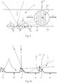
- Figure 3 shows a light guide 4 known from the prior art, which has such reflective structure elements 5a
- Figure 3a shows these reflection structure elements 5a in detail.
- Light which is coupled into the light guide 4 in the direction L1 (main light coupling direction) and is deflected in the two directions L2 (main light guide directions L2) is totally reflected on the rear side 40 and on the reflective structure elements 5a of the light guide 4 as shown and occurs via the front 2 from the light guide 4.
- the main light guiding direction of (or the) are also referred to as main light deflecting direction (s) L2.
- a reflective structural element 5a is preferably formed, as shown, by two structural element surfaces 5b, 5c which, as shown, are preferably flat and converge in an edge 5d. Light which strikes the front surface 5b directly is reflected by this to the front side 2, light which strikes the rear side 40 of the light guide 4 between two reflective structure elements 5a is also totally reflected there and, if necessary after further reflection on the surface 5b, radiated forward.
- Light emerges via the front 2 in the direction of the main light decoupling direction L3, which is generally parallel to the direction of travel of the vehicle in which the lighting device is arranged, and is imaged in an area in front of the vehicle.
- the reflection structure 5 in addition to the reflection structure elements 5a also includes decoupling means 20 for decoupling at least part of the light incident on the reflection structure 5 between the reflection structure elements 5 in a direction facing away from the decoupling point 2.
- Figure 4a shows in detail these coupling-out means, and as can be seen, the light beam shown in dashed lines (the light beam according to FIG Figure 3a was still totally reflected) is not totally reflected and emerges from the light guide to the rear, so it can no longer contribute to the formation of an undesired luminance spot.
- Total reflection in the area of the coupling-out means is thus prevented by means of the coupling-out means for at least some of the light beams impinging there; or contribute to the undesired luminance spot (s), which are thereby weakened or completely eliminated.
- the reflective structure elements 5a are arranged one behind the other in a main light guiding direction L2 and adjacent reflective structure elements 5a are arranged at a distance from one another.
- the reflection structure elements 5a have a prismatic shape or are designed as prisms.
- the reflective structure element boundary surfaces exist, as in connection with Figure 3 and 3a already mentioned, each of two planar delimiting partial surfaces 5b, 5c, which converge in a structural element edge 5d.
- the (local) angle 50b between the front planar reflective structure element delimiting surface 5b and the original delimiting surface 40 of the light guide 4 is selected in such a way that at least part, preferably essentially all of the light flux impinging on this area 5b is totally reflected and to the light decoupling point (front side) 2 is diverted.
- this angle 50b to the original delimiting surface 40 lies in a range of 40 ° -45 °.
- the angle 50c of the rear reflective structure element delimitation surface 5c is generally, as shown, greater than the front angle 50b.
- the reflective structure elements 5a in particular the edges 5d of the reflective structure elements 5a, are arranged equidistantly. It is also favorable if the height of the reflective structural elements 5a, i.e. the normal distance between the edges 5d of the reflective structural elements 5a and the original delimiting surface 40, increases as the light guide progresses. The “progression" begins with the light coupling area and takes place into the light guide.
- the outcoupling means comprise a number of elevations 20, which elevations 20 are arranged on the boundary surface 40 of the light guide 4, which has the reflection structure 5, in areas between adjacent reflection structure elements 5, pointing away from the boundary surface 40 to the outside, away from the uncoupling point 2.
- Such an elevation 20 is located between two reflective structural elements 5a, an elevation 20 preferably occupying essentially the entire area between the two structural elements 5a.
- the elevations 20 are designed and / or arranged in such a way that at least part of the light which strikes an elevation delimiting surface 20a, 20b, which elevation delimiting surface 20a, 20b in each case delimits an elevation 20 to the outside, via the elevation Boundary surface 20a, 20b emerges from the light guide 4, as shown in FIG Figure 4b is shown schematically on the basis of the dashed light beam.
- the elevations 20 preferably have a prismatic shape or are designed as prisms. Specifically, in the embodiment shown, the elevations 20 are each delimited by two flat delimiting partial surfaces 20a, 20b which converge in an elevation edge 20c. These raised edges can have slight rounded edges due to manufacturing technology, e.g. when manufacturing by means of an injection molding process.
- "Height extension” is the extension of the reflective structure elements transversely to a main light guiding direction, that is, the direction normal to the plane of the drawing in FIG Figure 4, 4a to understand.
- the angle 120a between an elevation delimiting surface 20a and the original delimiting surface 40 of the light guide 4 is preferably, as shown, less than the angle 120b between the rear elevation delimiting surface 20b.
- the angle (120b) between the rear elevation delimiting surface 20b and the original delimitation surface 40 is selected such that at least part of the light incident on the rear area of the elevation delimiting surface 20b exits the light guide 4 via the rear elevation delimiting surface 20b .
- the angle 120b is preferably chosen such that at least part of the light striking the rear area of the elevation delimiting surface 20b strikes the elevation delimiting surface 20b at an angle which is smaller than the limiting angle for total reflection in the local area under consideration Point of the elevation boundary surface 20b.
- the angle 120a between a front partial surface 20a and the original delimiting surface 40 is in a range of 12.5 ° -40 °
- the second, "rear" angle 120b is preferably in a range of 70 ° -90 °.
- edges 5d of the reflective structure elements 5 and the edges 20c of the elevations 20 preferably run parallel to one another.
- the height of the elevations 20 preferably decreases to the same extent as the height of the reflective structure elements 5a increases.
Landscapes
- Engineering & Computer Science (AREA)
- General Engineering & Computer Science (AREA)
- Physics & Mathematics (AREA)
- General Physics & Mathematics (AREA)
- Optics & Photonics (AREA)
- Mechanical Engineering (AREA)
- Planar Illumination Modules (AREA)
- Non-Portable Lighting Devices Or Systems Thereof (AREA)
Claims (20)
- Dispositif d'éclairage pour véhicules, en particulier pour véhicules automobiles, comprenant au moins une source de lumière et au moins un dispositif de guidage de lumière (1) associé à ladite au moins une source de lumière pour guider la lumière émise par ladite au moins une source de lumière et couplé dans le dispositif de guidage de lumière (1),
dans lequel le dispositif de guidage de lumière (1) comporte un ou plusieurs guides de lumière (4), ledit au moins un guide de lumière (4) a un ou plusieurs endroits de découplage (2) pour découpler au moins une partie de la lumière couplée, et
ledit au moins un guide de lumière (4) ayant une structure de réflexion (5) au moins dans une région d'une surface de délimitation (40) du guide de lumière (4) opposée audit au moins un endroit de découplage (2) pour dévier la lumière vers ledit au moins un endroit de découplage (2),
la structure de réflexion (5) comprenant un nombre d'éléments de structure de réflexion (5a), lesquels éléments de structure de réflexion (5a) sont conçus comme des dépressions dirigées vers l'intérieur dans le guide de lumière (4), lesquelles dépressions sont disposées et/ou conçues de telle sorte qu'au moins une partie du flux lumineux incident sur une surface d'élément de structure (5b, 5c) qui délimite l'élément de structure de réflexion (5) est totalement réfléchie au niveau de la surface d'élément de structure (5b, 5c),
caractérisé en ce que
la structure de réflexion (5) comprend des moyens de découplage (20) pour découpler au moins une partie de la lumière incidente sur la structure de réflexion (5) et entre les éléments de structure de réflexion (5) dans une direction s'éloignant dudit au moins un endroit de découplage (2), de sorte que des rayons lumineux sortent vers l'arrière du guide de lumière et ne peuvent plus contribuer à une tache de luminance ou à des taches de luminance,
lesdits moyens de découplage étant formés comme des saillies (20), lesdites saillies (20) ayant, par exemple, une forme prismatique ou étant formées comme des prismes, lesquelles saillies (20) sont disposées sur une surface de délimitation (40) du guide de lumière (4) ayant la structure de réflexion (5), dans des zones entre les éléments de structure de réflexion adjacents (5a), orientées vers l'extérieur de la surface de délimitation (40), en s'éloignant dudit au moins un endroit de découplage (2). - Dispositif d'éclairage selon la revendication 1, caractérisé en ce que les éléments de structure de réflexion (5a) sont disposés les uns derrière les autres dans une direction principale de guidage de la lumière (L2), les éléments de structure de réflexion adjacents (5a) étant disposés à distance les uns des autres.
- Dispositif d'éclairage selon la revendication 1 ou 2, caractérisé en ce que les saillies (20) sont conçues et/ou disposées de telle sorte qu'au moins une partie de la lumière incidente sur une surface de délimitation de saillie (20a, 20b), ladite surface de délimitation de saillie (20a, 20b) délimitant respectivement une saillie (20) vers l'extérieur, sort du guide de lumière (4) via la surface de délimitation de saillie (20a, 20b).
- Dispositif d'éclairage selon la revendication 3, caractérisé en ce que la surface de délimitation de saillie se compose de deux surfaces partielles de délimitation (20a, 20b) qui convergent en un bord de saillie (20c), et par exemple, au moins une des surfaces partielles de délimitation (20a, 20b), de préférence les deux, étant formées comme des surfaces planes.
- Dispositif d'éclairage selon l'une quelconque des revendications 1 à 4, caractérisé en ce que des saillies (20), de préférence toutes les saillies (20), s'étendent chacune sur toute la surface entre deux éléments de structure de réflexion (5).
- Dispositif d'éclairage selon l'une quelconque des revendications 1 à 5, caractérisé en ce que des saillies (20), de préférence toutes les saillies (20), s'étendent chacune sur sensiblement toute l'extension en hauteur d'au moins un élément structurel adjacent (5a).
- Dispositif d'éclairage selon l'une quelconque des revendications 1 à 6, caractérisé en ce que, dans une région avant telle que vue dans une direction principale de guidage de la lumière (L2), l'angle local (120a) entre la surface de délimitation de saillie (20a) et la surface de délimitation (40) initiale du guide de lumière (4) est inférieur à l'angle (120b) dans une région arrière de la surface de délimitation de saillie (20b), et de préférence, dans une région arrière de la surface de délimitation de saillie (20b) vue dans une direction principale de guidage de la lumière (L2), l'angle local (120b) entre la surface de délimitation de saillie (20b) et la surface de délimitation (40) initiale du guide de lumière (4) est sélectionné de telle sorte qu'au moins une partie de la lumière incidente sur la région arrière de la surface de délimitation de saillie (20b) sort du guide de lumière (4) via la région arrière de la surface de délimitation de saillie (20b).
- Dispositif d'éclairage selon la revendication 7, caractérisé en ce que, dans la région arrière de la surface de délimitation de saillie (20b) telle que vue dans une direction principale de guidage de la lumière (L2), l'angle local (120b) entre la surface de délimitation de saillie (20b) et la surface de délimitation (40) initiale du guide de lumière (4) est choisi tel qu'au moins une partie de la lumière incidente sur la région arrière de la surface de délimitation de saillie (20b) est incidente à un angle inférieur à l'angle de réflexion totale au point local de la surface de délimitation de saillie (20b) en question.
- Dispositif d'éclairage selon la revendication 7 ou 8, caractérisé en ce que, quant à une surface de délimitation de saillie qui est formée par deux surfaces partielles planes (20a, 20b), la surface partielle avant (20a) fait un premier angle (120a) avec la surface de délimitation initiale (40), qui se situe de préférence dans une plage de 12,5° à 40°, et/ou la surface partielle arrière (20b) fait un deuxième angle (120b) avec la surface de délimitation initiale (40), qui se situe de préférence dans une plage de 70° à 90°.
- Dispositif d'éclairage selon l'une quelconque des revendications 1 à 9, caractérisé en ce que les éléments de structure de réflexion (5) ont une forme prismatique ou sont formés comme des prismes.
- Dispositif d'éclairage selon l'une quelconque des revendications 1 à 10, caractérisé en ce que les surfaces de délimitation d'éléments de structure de réflexion se composent chacune de deux surfaces partielles de délimitation (5b, 5c) qui convergent en un bord d'élément de structure (5d), et au moins une des surfaces partielles d'éléments de structure de réflexion (5b, 5c), de préférence les deux, étant conçue (s) comme des surfaces planes.
- Dispositif d'éclairage selon la revendication 11, caractérisé en ce que, quant à une région avant de la surface de délimitation de l'élément de structure de réflexion (5b) telle que vue dans une direction principale de guidage de la lumière (L2), l'angle local (50b) entre la surface de délimitation de l'élément de structure de réflexion (5b) et la surface de délimitation (40) initiale du guide de lumière (4) est sélectionné de telle sorte qu'au moins une partie, de préférence sensiblement la totalité, du flux lumineux incident sur cette région (5b) est totalement réfléchie et déviée vers au moins un endroit de couplage de sortie de lumière (2), et de préférence, quant à une surface de délimitation d'élément de structure de réflexion frontale (5b), qui est plane, l'angle (50b) par rapport à la surface de délimitation (40) initiale se situe dans une plage de 40° à 45°.
- Dispositif d'éclairage selon la revendication 11 ou 12, caractérisé en ce que les bords (5d) des éléments de structure de réflexion (5a) et les saillies (20c) sont parallèles les uns aux autres.
- Dispositif d'éclairage selon l'une quelconque des revendications 1 à 13, caractérisé en ce que les éléments de structure de réflexion (5a), en particulier les bords (5d) des éléments de structure de réflexion (5), sont disposés de manière équidistante.
- Dispositif d'éclairage selon l'une quelconque des revendications 1 à 14, caractérisé en ce que la hauteur des éléments de structure de réflexion (5a), c'est-à-dire la distance normale des bords (5d) des éléments de structure de réflexion (5a) par rapport à la surface de délimitation (40) initiale, augmente en progressant le long du guide de lumière.
- Dispositif d'éclairage selon l'une quelconque des revendications 1 à 15, caractérisé en ce que la hauteur des saillies (20), c'est-à-dire la distance normale des bords (20c) des saillies (20) par rapport à la surface de délimitation (40) initiale, diminue en progressant le long du guide de lumière.
- Dispositif d'éclairage selon la revendication 15 et la revendication 16, caractérisé en ce que la hauteur des saillies (20) diminue dans la même mesure que la hauteur des éléments de structure de réflexion (5a) augmente.
- Dispositif d'éclairage selon l'une quelconque des revendications 1 à 17, caractérisé en ce que, contigu à au moins une surface de délimitation (2) dudit au moins un guide de lumière (4) situé du côté de la sortie de la lumière, au moins un, de préférence exactement un élément optique (200), par exemple au moins un élément optique à paroi épaisse, est prévu, dans lequel de la lumière est couplée via ledit au moins un endroit de couplage de sortie de lumière (2) du dispositif de guidage de lumière (1), laquelle lumière sort au niveau d'au moins une surface de sortie de lumière (210) de l'au moins un élément optique (200) pour former une fonction de lumière et/ou une distribution de lumière.
- Projecteur de véhicule, notamment projecteur de véhicule automobile, comprenant au moins un dispositif d'éclairage selon l'une quelconque des revendications 1 à 18.
- Véhicule, notamment véhicule automobile, comportant au moins un phare de véhicule selon la revendication 19.
Applications Claiming Priority (1)
| Application Number | Priority Date | Filing Date | Title |
|---|---|---|---|
| ATA50401/2014A AT515864B1 (de) | 2014-06-11 | 2014-06-11 | Beleuchtungsvorrichtung für Fahrzeuge sowie Kraftfahrzeugscheinwerfer |
Publications (3)
| Publication Number | Publication Date |
|---|---|
| EP2955432A2 EP2955432A2 (fr) | 2015-12-16 |
| EP2955432A3 EP2955432A3 (fr) | 2016-01-27 |
| EP2955432B1 true EP2955432B1 (fr) | 2021-08-04 |
Family
ID=53442510
Family Applications (1)
| Application Number | Title | Priority Date | Filing Date |
|---|---|---|---|
| EP15171347.6A Active EP2955432B1 (fr) | 2014-06-11 | 2015-06-10 | Dispositif d'eclairage pour vehicules |
Country Status (3)
| Country | Link |
|---|---|
| EP (1) | EP2955432B1 (fr) |
| CN (1) | CN105299558B (fr) |
| AT (1) | AT515864B1 (fr) |
Families Citing this family (12)
| Publication number | Priority date | Publication date | Assignee | Title |
|---|---|---|---|---|
| EP3472512A1 (fr) * | 2016-06-16 | 2019-04-24 | Signify Holding B.V. | Système d'éclairage utilisant une structure de guidage de lumière |
| DE102016115278B4 (de) | 2016-08-17 | 2023-11-02 | Automotive Lighting Reutlingen Gmbh | Beleuchtungseinrichtung für ein Kraftfahrzeug |
| DE102017102237A1 (de) | 2017-02-06 | 2018-08-09 | HELLA GmbH & Co. KGaA | Beleuchtungsvorrichtung für ein Kraftfahrzeug |
| CN108916805B (zh) * | 2017-03-22 | 2021-03-30 | 堤维西交通工业股份有限公司 | 车灯透镜 |
| TWM548641U (zh) | 2017-05-05 | 2017-09-11 | Depo Auto Parts Ind Co Ltd | 車燈光學模組及光導體 |
| CZ307956B6 (cs) | 2018-06-25 | 2019-09-11 | Varroc Lighting Systems, s.r.o. | Světlovodivý optický systém, zejména pro motorová vozidla |
| CN110187435B (zh) * | 2019-05-30 | 2020-12-01 | 山东光韵智能科技有限公司 | 一种远距离照明用多节点光纤及其制造方法 |
| CN110953547B (zh) * | 2019-12-10 | 2022-08-12 | 东风汽车有限公司 | 用于车灯的厚壁件及车灯 |
| CN112594650A (zh) * | 2020-12-16 | 2021-04-02 | 领为视觉智能科技(宁波)有限公司 | 一种利用光栅全反射的厚壁件及其应用 |
| CN112902105B (zh) * | 2021-03-25 | 2022-09-30 | 兰普电器股份有限公司 | 异型侧反射前照灯 |
| CN114719223B (zh) * | 2022-02-21 | 2023-08-04 | 岚图汽车科技有限公司 | 一种信号灯和机动车 |
| EP4368880A1 (fr) * | 2022-11-08 | 2024-05-15 | Hella Autotechnik Nova, s.r.o. | Guide de lumière pour lampe de véhicule automobile |
Citations (2)
| Publication number | Priority date | Publication date | Assignee | Title |
|---|---|---|---|---|
| US20120275190A1 (en) * | 2011-04-29 | 2012-11-01 | Coretronic Corporation | Light guide plate and light source module |
| US20120314448A1 (en) * | 2011-06-07 | 2012-12-13 | Koito Manufacturing Co., Ltd. | Vehicular Lamp |
Family Cites Families (11)
| Publication number | Priority date | Publication date | Assignee | Title |
|---|---|---|---|---|
| KR100785025B1 (ko) * | 2006-10-26 | 2007-12-12 | 삼성전자주식회사 | 디스플레이 소자용 양면 조명장치 및 이를 채용한 양면디스플레이 소자 |
| TW200900637A (en) * | 2007-04-12 | 2009-01-01 | Koninkl Philips Electronics Nv | Improved light guide and light-output device |
| TWM347535U (en) * | 2008-06-17 | 2008-12-21 | yun-heng Xu | Structural improvement of light guide plate |
| DE102008034052B4 (de) * | 2008-07-22 | 2019-08-14 | HELLA GmbH & Co. KGaA | Lichtleitkörper zur Anwendung als Positionslicht oder als Tagfahrlicht für ein Kraftfahrzeug |
| EP2325545B1 (fr) * | 2008-09-30 | 2014-07-16 | Sharp Kabushiki Kaisha | Dispositif d éclairage, dispositif d affichage et récepteur de télévision |
| WO2010124028A2 (fr) * | 2009-04-21 | 2010-10-28 | Vasylyev Sergiy V | Systèmes de collecte de lumière et d'éclairage à guide d'onde plan |
| JP2011040279A (ja) * | 2009-08-11 | 2011-02-24 | Sony Corp | 面状照明装置 |
| FR2977332B1 (fr) * | 2011-06-29 | 2017-08-11 | Valeo Vision | Guide de lumiere avec portion de decouplage et cache recoltant les rayons decouples |
| ITTV20110100A1 (it) * | 2011-07-13 | 2013-01-14 | Automotive Lighting Italia Spa | Fanale automobilistico |
| DE102012209337A1 (de) * | 2012-06-01 | 2013-12-05 | Automotive Lighting Reutlingen Gmbh | Lichtleiter und Lichtleitervorrichtung |
| DE102013204021B4 (de) * | 2012-06-01 | 2015-02-19 | Automotive Lighting Reutlingen Gmbh | Lichtleiter für eine Beleuchtungseinrichtung |
-
2014
- 2014-06-11 AT ATA50401/2014A patent/AT515864B1/de not_active IP Right Cessation
-
2015
- 2015-06-10 CN CN201510314511.5A patent/CN105299558B/zh active Active
- 2015-06-10 EP EP15171347.6A patent/EP2955432B1/fr active Active
Patent Citations (2)
| Publication number | Priority date | Publication date | Assignee | Title |
|---|---|---|---|---|
| US20120275190A1 (en) * | 2011-04-29 | 2012-11-01 | Coretronic Corporation | Light guide plate and light source module |
| US20120314448A1 (en) * | 2011-06-07 | 2012-12-13 | Koito Manufacturing Co., Ltd. | Vehicular Lamp |
Also Published As
| Publication number | Publication date |
|---|---|
| AT515864A1 (de) | 2015-12-15 |
| CN105299558A (zh) | 2016-02-03 |
| EP2955432A2 (fr) | 2015-12-16 |
| EP2955432A3 (fr) | 2016-01-27 |
| AT515864B1 (de) | 2016-03-15 |
| CN105299558B (zh) | 2018-11-16 |
Similar Documents
| Publication | Publication Date | Title |
|---|---|---|
| EP2955432B1 (fr) | Dispositif d'eclairage pour vehicules | |
| DE102014102496B4 (de) | Beleuchtungsvorrichtung für Fahrzeuge | |
| DE102013226181B4 (de) | Optisches Element, sowie Anordnung zur Lichtabgabe | |
| EP2799761B1 (fr) | Module d'éclairage de phare de véhicule automobile | |
| DE102013100557B4 (de) | Beleuchtungsvorrichtung für Fahrzeuge | |
| EP3899358B1 (fr) | Dispositif d'éclairage pour un phare de véhicule automobile ainsi que phare de véhicule automobile | |
| EP3653926B1 (fr) | Dispositif d'éclairage pour un phare de véhicule automobile ainsi que phare de véhicule automobile | |
| EP3084292B1 (fr) | Lampe de véhicule à moteur équipée d'un guide de lumière | |
| EP3063463B1 (fr) | Dispositif d'éclairage pour phare de véhicule automobile | |
| DE102011055429B4 (de) | Beleuchtungsvorrichtung für Fahrzeuge | |
| EP3112215A1 (fr) | Systeme de guides de lumiere destine a produire au moins une fonction d'eclairage et/ou une fonction de signalisation d'un phare de vehicule automobile | |
| EP3388734B1 (fr) | Unité optique primaire pour un module d'éclairage de phare de véhicule | |
| EP3112216A1 (fr) | Systeme de guides de lumiere destine a produire au moins une fonction d'eclairage et/ou une fonction de signalisation d'un phare de vehicule automobile | |
| EP3839324A1 (fr) | Dispositif d'éclairage pour un phare de véhicule automobile | |
| EP4202289B1 (fr) | Système optique pour un phare de véhicule automobile | |
| DE102005059958A1 (de) | Beleuchtungseinrichtung | |
| DE102012213547B4 (de) | Beleuchtungseinrichtung für ein Kraftfahrzeug | |
| DE102007046197B4 (de) | Signalleuchte für Kraftfahrzeuge | |
| DE102006053020A1 (de) | Linse sowie Scheinwerfer | |
| DE102007007943A1 (de) | Lichteinheit, insbesondere Scheinwerfer, für ein Fahrzeug | |
| EP3550205A1 (fr) | Conducteur de lumière pour un module lumineux de véhicule automobile | |
| DE102015210372B4 (de) | Signallichtmodul für ein Kraftfahrzeug | |
| DE102014201413A1 (de) | Lichtleiter | |
| WO2019158338A1 (fr) | Dispositif d'éclairage permettant de générer au moins deux fonctions d'éclairage ayant un aspect lumineux de type bande ou de ligne | |
| DE102007005932B4 (de) | Fahrzeugscheinwerfer mit Lichtleitelement |
Legal Events
| Date | Code | Title | Description |
|---|---|---|---|
| PUAI | Public reference made under article 153(3) epc to a published international application that has entered the european phase |
Free format text: ORIGINAL CODE: 0009012 |
|
| AK | Designated contracting states |
Kind code of ref document: A2 Designated state(s): AL AT BE BG CH CY CZ DE DK EE ES FI FR GB GR HR HU IE IS IT LI LT LU LV MC MK MT NL NO PL PT RO RS SE SI SK SM TR |
|
| AX | Request for extension of the european patent |
Extension state: BA ME |
|
| PUAL | Search report despatched |
Free format text: ORIGINAL CODE: 0009013 |
|
| AK | Designated contracting states |
Kind code of ref document: A3 Designated state(s): AL AT BE BG CH CY CZ DE DK EE ES FI FR GB GR HR HU IE IS IT LI LT LU LV MC MK MT NL NO PL PT RO RS SE SI SK SM TR |
|
| AX | Request for extension of the european patent |
Extension state: BA ME |
|
| RIC1 | Information provided on ipc code assigned before grant |
Ipc: F21S 8/10 20060101ALI20151221BHEP Ipc: B60Q 1/00 20060101ALN20151221BHEP Ipc: F21V 8/00 20060101AFI20151221BHEP |
|
| 17P | Request for examination filed |
Effective date: 20160704 |
|
| RBV | Designated contracting states (corrected) |
Designated state(s): AL AT BE BG CH CY CZ DE DK EE ES FI FR GB GR HR HU IE IS IT LI LT LU LV MC MK MT NL NO PL PT RO RS SE SI SK SM TR |
|
| RAP1 | Party data changed (applicant data changed or rights of an application transferred) |
Owner name: ZKW GROUP GMBH |
|
| STAA | Information on the status of an ep patent application or granted ep patent |
Free format text: STATUS: EXAMINATION IS IN PROGRESS |
|
| 17Q | First examination report despatched |
Effective date: 20190523 |
|
| GRAP | Despatch of communication of intention to grant a patent |
Free format text: ORIGINAL CODE: EPIDOSNIGR1 |
|
| STAA | Information on the status of an ep patent application or granted ep patent |
Free format text: STATUS: GRANT OF PATENT IS INTENDED |
|
| RIC1 | Information provided on ipc code assigned before grant |
Ipc: F21V 8/00 20060101AFI20201202BHEP Ipc: F21S 43/237 20180101ALI20201202BHEP Ipc: F21S 43/245 20180101ALI20201202BHEP Ipc: B60Q 1/00 20060101ALN20201202BHEP Ipc: F21S 43/251 20180101ALI20201202BHEP |
|
| INTG | Intention to grant announced |
Effective date: 20201222 |
|
| GRAJ | Information related to disapproval of communication of intention to grant by the applicant or resumption of examination proceedings by the epo deleted |
Free format text: ORIGINAL CODE: EPIDOSDIGR1 |
|
| STAA | Information on the status of an ep patent application or granted ep patent |
Free format text: STATUS: EXAMINATION IS IN PROGRESS |
|
| INTC | Intention to grant announced (deleted) | ||
| RIC1 | Information provided on ipc code assigned before grant |
Ipc: F21V 8/00 20060101AFI20210422BHEP Ipc: F21S 43/237 20180101ALI20210422BHEP Ipc: F21S 43/245 20180101ALI20210422BHEP Ipc: F21S 43/251 20180101ALI20210422BHEP Ipc: B60Q 1/00 20060101ALN20210422BHEP |
|
| GRAP | Despatch of communication of intention to grant a patent |
Free format text: ORIGINAL CODE: EPIDOSNIGR1 |
|
| STAA | Information on the status of an ep patent application or granted ep patent |
Free format text: STATUS: GRANT OF PATENT IS INTENDED |
|
| GRAS | Grant fee paid |
Free format text: ORIGINAL CODE: EPIDOSNIGR3 |
|
| GRAA | (expected) grant |
Free format text: ORIGINAL CODE: 0009210 |
|
| STAA | Information on the status of an ep patent application or granted ep patent |
Free format text: STATUS: THE PATENT HAS BEEN GRANTED |
|
| INTG | Intention to grant announced |
Effective date: 20210616 |
|
| RIC1 | Information provided on ipc code assigned before grant |
Ipc: F21V 8/00 20060101AFI20210608BHEP Ipc: F21S 43/237 20180101ALI20210608BHEP Ipc: F21S 43/245 20180101ALI20210608BHEP Ipc: F21S 43/251 20180101ALI20210608BHEP Ipc: B60Q 1/00 20060101ALN20210608BHEP |
|
| AK | Designated contracting states |
Kind code of ref document: B1 Designated state(s): AL AT BE BG CH CY CZ DE DK EE ES FI FR GB GR HR HU IE IS IT LI LT LU LV MC MK MT NL NO PL PT RO RS SE SI SK SM TR |
|
| REG | Reference to a national code |
Ref country code: GB Ref legal event code: FG4D Free format text: NOT ENGLISH |
|
| REG | Reference to a national code |
Ref country code: AT Ref legal event code: REF Ref document number: 1417333 Country of ref document: AT Kind code of ref document: T Effective date: 20210815 |
|
| REG | Reference to a national code |
Ref country code: CH Ref legal event code: EP |
|
| REG | Reference to a national code |
Ref country code: DE Ref legal event code: R096 Ref document number: 502015015021 Country of ref document: DE |
|
| REG | Reference to a national code |
Ref country code: IE Ref legal event code: FG4D Free format text: LANGUAGE OF EP DOCUMENT: GERMAN |
|
| REG | Reference to a national code |
Ref country code: LT Ref legal event code: MG9D |
|
| REG | Reference to a national code |
Ref country code: NL Ref legal event code: MP Effective date: 20210804 |
|
| PG25 | Lapsed in a contracting state [announced via postgrant information from national office to epo] |
Ref country code: HR Free format text: LAPSE BECAUSE OF FAILURE TO SUBMIT A TRANSLATION OF THE DESCRIPTION OR TO PAY THE FEE WITHIN THE PRESCRIBED TIME-LIMIT Effective date: 20210804 Ref country code: SE Free format text: LAPSE BECAUSE OF FAILURE TO SUBMIT A TRANSLATION OF THE DESCRIPTION OR TO PAY THE FEE WITHIN THE PRESCRIBED TIME-LIMIT Effective date: 20210804 Ref country code: RS Free format text: LAPSE BECAUSE OF FAILURE TO SUBMIT A TRANSLATION OF THE DESCRIPTION OR TO PAY THE FEE WITHIN THE PRESCRIBED TIME-LIMIT Effective date: 20210804 Ref country code: PT Free format text: LAPSE BECAUSE OF FAILURE TO SUBMIT A TRANSLATION OF THE DESCRIPTION OR TO PAY THE FEE WITHIN THE PRESCRIBED TIME-LIMIT Effective date: 20211206 Ref country code: NO Free format text: LAPSE BECAUSE OF FAILURE TO SUBMIT A TRANSLATION OF THE DESCRIPTION OR TO PAY THE FEE WITHIN THE PRESCRIBED TIME-LIMIT Effective date: 20211104 Ref country code: ES Free format text: LAPSE BECAUSE OF FAILURE TO SUBMIT A TRANSLATION OF THE DESCRIPTION OR TO PAY THE FEE WITHIN THE PRESCRIBED TIME-LIMIT Effective date: 20210804 Ref country code: FI Free format text: LAPSE BECAUSE OF FAILURE TO SUBMIT A TRANSLATION OF THE DESCRIPTION OR TO PAY THE FEE WITHIN THE PRESCRIBED TIME-LIMIT Effective date: 20210804 Ref country code: BG Free format text: LAPSE BECAUSE OF FAILURE TO SUBMIT A TRANSLATION OF THE DESCRIPTION OR TO PAY THE FEE WITHIN THE PRESCRIBED TIME-LIMIT Effective date: 20211104 Ref country code: LT Free format text: LAPSE BECAUSE OF FAILURE TO SUBMIT A TRANSLATION OF THE DESCRIPTION OR TO PAY THE FEE WITHIN THE PRESCRIBED TIME-LIMIT Effective date: 20210804 |
|
| PG25 | Lapsed in a contracting state [announced via postgrant information from national office to epo] |
Ref country code: PL Free format text: LAPSE BECAUSE OF FAILURE TO SUBMIT A TRANSLATION OF THE DESCRIPTION OR TO PAY THE FEE WITHIN THE PRESCRIBED TIME-LIMIT Effective date: 20210804 Ref country code: LV Free format text: LAPSE BECAUSE OF FAILURE TO SUBMIT A TRANSLATION OF THE DESCRIPTION OR TO PAY THE FEE WITHIN THE PRESCRIBED TIME-LIMIT Effective date: 20210804 Ref country code: GR Free format text: LAPSE BECAUSE OF FAILURE TO SUBMIT A TRANSLATION OF THE DESCRIPTION OR TO PAY THE FEE WITHIN THE PRESCRIBED TIME-LIMIT Effective date: 20211105 |
|
| PG25 | Lapsed in a contracting state [announced via postgrant information from national office to epo] |
Ref country code: NL Free format text: LAPSE BECAUSE OF FAILURE TO SUBMIT A TRANSLATION OF THE DESCRIPTION OR TO PAY THE FEE WITHIN THE PRESCRIBED TIME-LIMIT Effective date: 20210804 |
|
| PG25 | Lapsed in a contracting state [announced via postgrant information from national office to epo] |
Ref country code: DK Free format text: LAPSE BECAUSE OF FAILURE TO SUBMIT A TRANSLATION OF THE DESCRIPTION OR TO PAY THE FEE WITHIN THE PRESCRIBED TIME-LIMIT Effective date: 20210804 |
|
| REG | Reference to a national code |
Ref country code: DE Ref legal event code: R097 Ref document number: 502015015021 Country of ref document: DE |
|
| PG25 | Lapsed in a contracting state [announced via postgrant information from national office to epo] |
Ref country code: SM Free format text: LAPSE BECAUSE OF FAILURE TO SUBMIT A TRANSLATION OF THE DESCRIPTION OR TO PAY THE FEE WITHIN THE PRESCRIBED TIME-LIMIT Effective date: 20210804 Ref country code: SK Free format text: LAPSE BECAUSE OF FAILURE TO SUBMIT A TRANSLATION OF THE DESCRIPTION OR TO PAY THE FEE WITHIN THE PRESCRIBED TIME-LIMIT Effective date: 20210804 Ref country code: RO Free format text: LAPSE BECAUSE OF FAILURE TO SUBMIT A TRANSLATION OF THE DESCRIPTION OR TO PAY THE FEE WITHIN THE PRESCRIBED TIME-LIMIT Effective date: 20210804 Ref country code: EE Free format text: LAPSE BECAUSE OF FAILURE TO SUBMIT A TRANSLATION OF THE DESCRIPTION OR TO PAY THE FEE WITHIN THE PRESCRIBED TIME-LIMIT Effective date: 20210804 Ref country code: CZ Free format text: LAPSE BECAUSE OF FAILURE TO SUBMIT A TRANSLATION OF THE DESCRIPTION OR TO PAY THE FEE WITHIN THE PRESCRIBED TIME-LIMIT Effective date: 20210804 Ref country code: AL Free format text: LAPSE BECAUSE OF FAILURE TO SUBMIT A TRANSLATION OF THE DESCRIPTION OR TO PAY THE FEE WITHIN THE PRESCRIBED TIME-LIMIT Effective date: 20210804 |
|
| PLBE | No opposition filed within time limit |
Free format text: ORIGINAL CODE: 0009261 |
|
| STAA | Information on the status of an ep patent application or granted ep patent |
Free format text: STATUS: NO OPPOSITION FILED WITHIN TIME LIMIT |
|
| 26N | No opposition filed |
Effective date: 20220506 |
|
| PG25 | Lapsed in a contracting state [announced via postgrant information from national office to epo] |
Ref country code: IT Free format text: LAPSE BECAUSE OF FAILURE TO SUBMIT A TRANSLATION OF THE DESCRIPTION OR TO PAY THE FEE WITHIN THE PRESCRIBED TIME-LIMIT Effective date: 20210804 |
|
| PG25 | Lapsed in a contracting state [announced via postgrant information from national office to epo] |
Ref country code: SI Free format text: LAPSE BECAUSE OF FAILURE TO SUBMIT A TRANSLATION OF THE DESCRIPTION OR TO PAY THE FEE WITHIN THE PRESCRIBED TIME-LIMIT Effective date: 20210804 |
|
| PG25 | Lapsed in a contracting state [announced via postgrant information from national office to epo] |
Ref country code: MC Free format text: LAPSE BECAUSE OF FAILURE TO SUBMIT A TRANSLATION OF THE DESCRIPTION OR TO PAY THE FEE WITHIN THE PRESCRIBED TIME-LIMIT Effective date: 20210804 |
|
| REG | Reference to a national code |
Ref country code: CH Ref legal event code: PL |
|
| REG | Reference to a national code |
Ref country code: BE Ref legal event code: MM Effective date: 20220630 |
|
| GBPC | Gb: european patent ceased through non-payment of renewal fee |
Effective date: 20220610 |
|
| PG25 | Lapsed in a contracting state [announced via postgrant information from national office to epo] |
Ref country code: LU Free format text: LAPSE BECAUSE OF NON-PAYMENT OF DUE FEES Effective date: 20220610 Ref country code: LI Free format text: LAPSE BECAUSE OF NON-PAYMENT OF DUE FEES Effective date: 20220630 Ref country code: IE Free format text: LAPSE BECAUSE OF NON-PAYMENT OF DUE FEES Effective date: 20220610 Ref country code: CH Free format text: LAPSE BECAUSE OF NON-PAYMENT OF DUE FEES Effective date: 20220630 |
|
| PG25 | Lapsed in a contracting state [announced via postgrant information from national office to epo] |
Ref country code: GB Free format text: LAPSE BECAUSE OF NON-PAYMENT OF DUE FEES Effective date: 20220610 Ref country code: BE Free format text: LAPSE BECAUSE OF NON-PAYMENT OF DUE FEES Effective date: 20220630 |
|
| P01 | Opt-out of the competence of the unified patent court (upc) registered |
Effective date: 20230528 |
|
| REG | Reference to a national code |
Ref country code: AT Ref legal event code: MM01 Ref document number: 1417333 Country of ref document: AT Kind code of ref document: T Effective date: 20220610 |
|
| PG25 | Lapsed in a contracting state [announced via postgrant information from national office to epo] |
Ref country code: AT Free format text: LAPSE BECAUSE OF NON-PAYMENT OF DUE FEES Effective date: 20220610 |
|
| PG25 | Lapsed in a contracting state [announced via postgrant information from national office to epo] |
Ref country code: HU Free format text: LAPSE BECAUSE OF FAILURE TO SUBMIT A TRANSLATION OF THE DESCRIPTION OR TO PAY THE FEE WITHIN THE PRESCRIBED TIME-LIMIT; INVALID AB INITIO Effective date: 20150610 |
|
| PG25 | Lapsed in a contracting state [announced via postgrant information from national office to epo] |
Ref country code: MK Free format text: LAPSE BECAUSE OF FAILURE TO SUBMIT A TRANSLATION OF THE DESCRIPTION OR TO PAY THE FEE WITHIN THE PRESCRIBED TIME-LIMIT Effective date: 20210804 Ref country code: CY Free format text: LAPSE BECAUSE OF FAILURE TO SUBMIT A TRANSLATION OF THE DESCRIPTION OR TO PAY THE FEE WITHIN THE PRESCRIBED TIME-LIMIT Effective date: 20210804 |
|
| PG25 | Lapsed in a contracting state [announced via postgrant information from national office to epo] |
Ref country code: TR Free format text: LAPSE BECAUSE OF FAILURE TO SUBMIT A TRANSLATION OF THE DESCRIPTION OR TO PAY THE FEE WITHIN THE PRESCRIBED TIME-LIMIT Effective date: 20210804 |
|
| PG25 | Lapsed in a contracting state [announced via postgrant information from national office to epo] |
Ref country code: MT Free format text: LAPSE BECAUSE OF FAILURE TO SUBMIT A TRANSLATION OF THE DESCRIPTION OR TO PAY THE FEE WITHIN THE PRESCRIBED TIME-LIMIT Effective date: 20210804 |
|
| PGFP | Annual fee paid to national office [announced via postgrant information from national office to epo] |
Ref country code: DE Payment date: 20250618 Year of fee payment: 11 |
|
| PGFP | Annual fee paid to national office [announced via postgrant information from national office to epo] |
Ref country code: FR Payment date: 20250624 Year of fee payment: 11 |