EP2799761B1 - Module d'éclairage de phare de véhicule automobile - Google Patents
Module d'éclairage de phare de véhicule automobile Download PDFInfo
- Publication number
- EP2799761B1 EP2799761B1 EP14160613.7A EP14160613A EP2799761B1 EP 2799761 B1 EP2799761 B1 EP 2799761B1 EP 14160613 A EP14160613 A EP 14160613A EP 2799761 B1 EP2799761 B1 EP 2799761B1
- Authority
- EP
- European Patent Office
- Prior art keywords
- light
- diaphragm
- optics
- bulge
- module
- Prior art date
- Legal status (The legal status is an assumption and is not a legal conclusion. Google has not performed a legal analysis and makes no representation as to the accuracy of the status listed.)
- Active
Links
Images


Classifications
-
- F—MECHANICAL ENGINEERING; LIGHTING; HEATING; WEAPONS; BLASTING
- F21—LIGHTING
- F21S—NON-PORTABLE LIGHTING DEVICES; SYSTEMS THEREOF; VEHICLE LIGHTING DEVICES SPECIALLY ADAPTED FOR VEHICLE EXTERIORS
- F21S41/00—Illuminating devices specially adapted for vehicle exteriors, e.g. headlamps
- F21S41/10—Illuminating devices specially adapted for vehicle exteriors, e.g. headlamps characterised by the light source
- F21S41/14—Illuminating devices specially adapted for vehicle exteriors, e.g. headlamps characterised by the light source characterised by the type of light source
- F21S41/141—Light emitting diodes [LED]
- F21S41/147—Light emitting diodes [LED] the main emission direction of the LED being angled to the optical axis of the illuminating device
-
- F—MECHANICAL ENGINEERING; LIGHTING; HEATING; WEAPONS; BLASTING
- F21—LIGHTING
- F21S—NON-PORTABLE LIGHTING DEVICES; SYSTEMS THEREOF; VEHICLE LIGHTING DEVICES SPECIALLY ADAPTED FOR VEHICLE EXTERIORS
- F21S41/00—Illuminating devices specially adapted for vehicle exteriors, e.g. headlamps
- F21S41/20—Illuminating devices specially adapted for vehicle exteriors, e.g. headlamps characterised by refractors, transparent cover plates, light guides or filters
- F21S41/25—Projection lenses
- F21S41/275—Lens surfaces, e.g. coatings or surface structures
-
- F—MECHANICAL ENGINEERING; LIGHTING; HEATING; WEAPONS; BLASTING
- F21—LIGHTING
- F21S—NON-PORTABLE LIGHTING DEVICES; SYSTEMS THEREOF; VEHICLE LIGHTING DEVICES SPECIALLY ADAPTED FOR VEHICLE EXTERIORS
- F21S41/00—Illuminating devices specially adapted for vehicle exteriors, e.g. headlamps
- F21S41/20—Illuminating devices specially adapted for vehicle exteriors, e.g. headlamps characterised by refractors, transparent cover plates, light guides or filters
- F21S41/285—Refractors, transparent cover plates, light guides or filters not provided in groups F21S41/24-F21S41/28
-
- F—MECHANICAL ENGINEERING; LIGHTING; HEATING; WEAPONS; BLASTING
- F21—LIGHTING
- F21S—NON-PORTABLE LIGHTING DEVICES; SYSTEMS THEREOF; VEHICLE LIGHTING DEVICES SPECIALLY ADAPTED FOR VEHICLE EXTERIORS
- F21S41/00—Illuminating devices specially adapted for vehicle exteriors, e.g. headlamps
- F21S41/30—Illuminating devices specially adapted for vehicle exteriors, e.g. headlamps characterised by reflectors
- F21S41/32—Optical layout thereof
- F21S41/321—Optical layout thereof the reflector being a surface of revolution or a planar surface, e.g. truncated
-
- F—MECHANICAL ENGINEERING; LIGHTING; HEATING; WEAPONS; BLASTING
- F21—LIGHTING
- F21S—NON-PORTABLE LIGHTING DEVICES; SYSTEMS THEREOF; VEHICLE LIGHTING DEVICES SPECIALLY ADAPTED FOR VEHICLE EXTERIORS
- F21S41/00—Illuminating devices specially adapted for vehicle exteriors, e.g. headlamps
- F21S41/30—Illuminating devices specially adapted for vehicle exteriors, e.g. headlamps characterised by reflectors
- F21S41/32—Optical layout thereof
- F21S41/322—Optical layout thereof the reflector using total internal reflection
-
- F—MECHANICAL ENGINEERING; LIGHTING; HEATING; WEAPONS; BLASTING
- F21—LIGHTING
- F21S—NON-PORTABLE LIGHTING DEVICES; SYSTEMS THEREOF; VEHICLE LIGHTING DEVICES SPECIALLY ADAPTED FOR VEHICLE EXTERIORS
- F21S41/00—Illuminating devices specially adapted for vehicle exteriors, e.g. headlamps
- F21S41/30—Illuminating devices specially adapted for vehicle exteriors, e.g. headlamps characterised by reflectors
- F21S41/32—Optical layout thereof
- F21S41/33—Multi-surface reflectors, e.g. reflectors with facets or reflectors with portions of different curvature
- F21S41/334—Multi-surface reflectors, e.g. reflectors with facets or reflectors with portions of different curvature the reflector consisting of patch like sectors
- F21S41/336—Multi-surface reflectors, e.g. reflectors with facets or reflectors with portions of different curvature the reflector consisting of patch like sectors with discontinuity at the junction between adjacent areas
-
- F—MECHANICAL ENGINEERING; LIGHTING; HEATING; WEAPONS; BLASTING
- F21—LIGHTING
- F21S—NON-PORTABLE LIGHTING DEVICES; SYSTEMS THEREOF; VEHICLE LIGHTING DEVICES SPECIALLY ADAPTED FOR VEHICLE EXTERIORS
- F21S41/00—Illuminating devices specially adapted for vehicle exteriors, e.g. headlamps
- F21S41/30—Illuminating devices specially adapted for vehicle exteriors, e.g. headlamps characterised by reflectors
- F21S41/32—Optical layout thereof
- F21S41/33—Multi-surface reflectors, e.g. reflectors with facets or reflectors with portions of different curvature
- F21S41/338—Multi-surface reflectors, e.g. reflectors with facets or reflectors with portions of different curvature the reflector having surface portions added to its general concavity
-
- F—MECHANICAL ENGINEERING; LIGHTING; HEATING; WEAPONS; BLASTING
- F21—LIGHTING
- F21S—NON-PORTABLE LIGHTING DEVICES; SYSTEMS THEREOF; VEHICLE LIGHTING DEVICES SPECIALLY ADAPTED FOR VEHICLE EXTERIORS
- F21S41/00—Illuminating devices specially adapted for vehicle exteriors, e.g. headlamps
- F21S41/30—Illuminating devices specially adapted for vehicle exteriors, e.g. headlamps characterised by reflectors
- F21S41/32—Optical layout thereof
- F21S41/36—Combinations of two or more separate reflectors
- F21S41/365—Combinations of two or more separate reflectors successively reflecting the light
-
- F—MECHANICAL ENGINEERING; LIGHTING; HEATING; WEAPONS; BLASTING
- F21—LIGHTING
- F21S—NON-PORTABLE LIGHTING DEVICES; SYSTEMS THEREOF; VEHICLE LIGHTING DEVICES SPECIALLY ADAPTED FOR VEHICLE EXTERIORS
- F21S41/00—Illuminating devices specially adapted for vehicle exteriors, e.g. headlamps
- F21S41/40—Illuminating devices specially adapted for vehicle exteriors, e.g. headlamps characterised by screens, non-reflecting members, light-shielding members or fixed shades
- F21S41/43—Illuminating devices specially adapted for vehicle exteriors, e.g. headlamps characterised by screens, non-reflecting members, light-shielding members or fixed shades characterised by the shape thereof
-
- F—MECHANICAL ENGINEERING; LIGHTING; HEATING; WEAPONS; BLASTING
- F21—LIGHTING
- F21S—NON-PORTABLE LIGHTING DEVICES; SYSTEMS THEREOF; VEHICLE LIGHTING DEVICES SPECIALLY ADAPTED FOR VEHICLE EXTERIORS
- F21S41/00—Illuminating devices specially adapted for vehicle exteriors, e.g. headlamps
- F21S41/60—Illuminating devices specially adapted for vehicle exteriors, e.g. headlamps characterised by a variable light distribution
- F21S41/65—Illuminating devices specially adapted for vehicle exteriors, e.g. headlamps characterised by a variable light distribution by acting on light sources
- F21S41/663—Illuminating devices specially adapted for vehicle exteriors, e.g. headlamps characterised by a variable light distribution by acting on light sources by switching light sources
-
- F—MECHANICAL ENGINEERING; LIGHTING; HEATING; WEAPONS; BLASTING
- F21—LIGHTING
- F21W—INDEXING SCHEME ASSOCIATED WITH SUBCLASSES F21K, F21L, F21S and F21V, RELATING TO USES OR APPLICATIONS OF LIGHTING DEVICES OR SYSTEMS
- F21W2102/00—Exterior vehicle lighting devices for illuminating purposes
- F21W2102/10—Arrangement or contour of the emitted light
- F21W2102/17—Arrangement or contour of the emitted light for regions other than high beam or low beam
- F21W2102/18—Arrangement or contour of the emitted light for regions other than high beam or low beam for overhead signs
Definitions
- the present invention relates to a light module for a motor vehicle headlight according to the preamble of claim 1.
- Such a light module is from DE 10 2006 061 751 A1 and also from the JP 2012/216408 known.
- Such a module generates a light distribution with a cut-off line such as e.g. a low beam or fog light.
- a cut-off line such as e.g. a low beam or fog light.
- such a light module with at least one further light source and further primary optics is also suitable for generating a high beam distribution using the same secondary optics.
- Such light modules are also known as projection systems. They consist of one or more LEDs as light sources with associated lens attachments Primary optics, a horizontal diaphragm and a projection lens as secondary optics. From the DE 10 2011 004 569 A1 a light module is known which uses a reflector as secondary optics. The invention can also be used with such light modules.
- the screen creates a cut-off line that prevents oncoming vehicles from being dazzled.
- a disadvantage of known projection systems is that only a small amount of light reaches the area above the cut-off line, so that objects such as e.g. Traffic signs are not sufficiently illuminated.
- objects such as e.g. Traffic signs are not sufficiently illuminated.
- This area is often referred to as the overhead area.
- the degrees for the vertical direction relate to deviations from a longitudinal direction of the motor vehicle upwards.
- the degrees for the horizontal direction refer to deviations from the longitudinal direction to the right and left.
- the vertex of the angle is in the light module.
- it is from the EP 1 980 787 known to use a lens as secondary optics that has structures that direct light into the overhead area.
- a similar solution is in the EP 1 464 890 described. It is disadvantageous in each case that such structures are visible to the outside for a viewer of the headlight, which is Appearance of the headlight impaired. Particularly at night, the light-scattering areas of the lens are visible to the viewer as bright points, lines or surfaces and are therefore disadvantageous for the appearance of the headlight.
- the one from the DE 10 2009 020 593 known object light is directed into the overhead area by a large number of small prismatic structures on a lens.
- This solution also has the disadvantage that the small prism structures are visible to the viewer of the module.
- the microprisms direct light in a preferred spatial direction, but at their edges, which are rounded in real parts, the microprisms act as scattering structures that scatter light over a large solid angle range.
- the small prisms in contrast to the rest of the surface of the lens, appear bright when the lens is viewed from an area above the light-dark boundary of the light distribution generated by the module. This is typically the case when looking at a car from the front, the headlight of which uses a projection lens provided with such prismatic structures as secondary optics. This appearance is often undesirable.
- the object of the invention is to specify a light module of the type mentioned above, which light module generates a rule-compliant overhead light distribution as a supplement to a rule-compliant low beam distribution without the need for additional components and without the external appearance of the module being influenced.
- the light module should also allow a high beam distribution to be generated.
- Objects such as those from the U.S. 6,736,533 or the EP 624 753 or the DE 10 2006 061 751 A1 are known, are ruled out because they at least partially block the beam path required for the high beam and usually require an additional component.
- the present invention differs in that the primary optics has a light entry surface having several partial surfaces, a light exit surface and a light deflecting side surface and a bulge in its side surface, the bulge being in a part of the side surface of the ancillary optics which faces the same side as the second side of the bezel. Light which at least contributes to the overhead lighting therefore passes the screen in particular outside the contiguous outer edge.
- the primary optics are arranged in relation to the secondary optics in such a way that the secondary optics light of the intermediate light distribution, which passes the cover on an upper side of the cover, in a first beam path into one below the light-dark Limit in the second light distribution area, the primary optics being set up to deflect part of the light emanating from the light source so that it passes the diaphragm in an area below the diaphragm and from the secondary optics in a second beam path is distributed in an area lying above the cut-off line in the second light distribution.
- the diaphragm surface is preferably oriented essentially parallel to the horizon.
- the first side of the bezel is an upper side.
- the first beam path runs up to the diaphragm edge above the diaphragm surface.
- the area on the first side of the cut-off line in the second light distribution is the light area of a low beam distribution. In the second The light distribution is the light area below the cut-off line.
- the second side of the panel is then an underside of the panel.
- the second beam path runs at least as far as the diaphragm edge below the diaphragm surface and the area which is on the second side of the light-dark boundary in the second light distribution is thus above this light-dark boundary. This is the darker area of a low beam distribution.
- the so-called overhead area lies in this darker area of the low beam distribution.
- An essential element of the invention is that part of the light emanating from the light source, which is used for the low beam, is directed by the primary optics under the diaphragm in such a way that it is distributed by the secondary optics into the overhead area.
- the preposition indicating the location relates to an orientation of the light module in space when the light module is used as intended in a motor vehicle that stands on a level surface.
- the invention provides overhead lighting that supplements a low beam distribution and is used, for example, to illuminate gantries.
- a particular advantage is that the invention allows the provision of the overhead lighting with a projection module, that uses semiconductor light sources with primary optics and a mirror shutter.
- the invention can be implemented by changing the primary optics and does not require any changes to the secondary optics. The secondary optics remain unchanged and are illuminated in such a way that they direct light in the direction required for the desired overhead lighting.
- the invention can be used both with light modules that use a projection lens as secondary optics and with light modules that use a reflector as secondary optics.
- the diaphragm preferably extends approximately horizontally between the primary optics and the secondary optics.
- the light source is a semiconductor light source, in particular a light-emitting diode, mounted on a mounting support or a printed circuit board.
- a first side of the panel is implemented as a reflective surface. It is also preferred that both sides of the panel are implemented as reflective surfaces.
- the primary optics have a light entry area having a plurality of partial areas, a light exit area and a side area that deflects light.
- the light entry surface has a central part and peripheral parts adjoining the central part and that the light source and the various parts of the light entry surface are arranged relative to one another in such a way that the light undergoes various changes in direction when passing through the ancillary optics, which are caused by refraction and Reflection.
- the light module is designed so that light, the path of which runs on the first side of the diaphragm, undergoes a refraction when the light enters, which occurs over a peripheral part of the light entry surface and then experiences total internal reflection on a side surface and a Refraction undergoes light exit over the light exit surface.
- the primary optics are set up to allow light which enters the light-conducting material of the primary optics via the central part of the light entry surface to reach the light exit surface directly without being reflected on a side wall.
- the primary optics have a bulge in its side surface, the bulge lying in a part of the side surface of the primary optics which faces the same side as the second side of the screen.
- the bulge is integral with the rest of the primary optics and protrudes as an elevation from the side surface of the rest of the primary optics and is delimited by a bulge side surface and a bulge light exit surface.
- the bulge lies in a part of the side surface of the primary optics which is closer to the light exit surface of the primary optics than to the light entry surface.
- the bulge is a bulge light exit surface which adjoins the rest of the light exit surface of the primary optics, the transition from the bulge light exit surface to the rest of the light exit surface taking place without a kink.
- the bulge side surface and the bulge light exit surface are arranged in relation to their alignment with the light of the light source incident on the bulge side surface so that they at least part of this light on the second side of the diaphragm along the diaphragm onto the secondary optics directs.
- the bulge and, in particular, its light exit surface is designed such that the overhead area of the light distribution is illuminated by the light emerging from the light exit surface.
- Another preferred embodiment is characterized in that the bulge is implemented as an elevation from the rest of the primary optics.
- the bulge lies to the left or right of a plane which is spanned by the optical axis of the secondary optics and a vertical. This facilitates the generation of an overhead light distribution which has a sufficient width.
- Fig. 1 shows in detail a light distribution generated by a light module according to the invention on a measuring screen, the measuring screen being at a distance of several meters in front of the headlight.
- a light distribution results when the light module is used as intended in a motor vehicle headlight in the motor vehicle.
- the line H corresponds to the height of the horizon in front of the vehicle standing on level ground.
- Line V divides the area in front of the vehicle into a right and a left half-space.
- the intersection point HV marks a zero point on both lines, from which deviations are indicated in degrees of angle.
- the area 11 represents a rule-compliant light distribution for right-hand traffic.
- the area 11 hatched with large line spacings is brightly illuminated and is delimited at the top by a light-dark boundary 13.
- This low beam component is used to illuminate the road in front of the vehicle and the areas left and right of the street.
- the cut-off line is asymmetrically high, on the one hand to avoid dazzling oncoming traffic on the left-hand side and on the other hand to achieve the greatest possible range on the right-hand side of the lane.
- the area 12 hatched with smaller line spacings above the light-dark border represents the so-called overhead area. This area is less brightly illuminated than the area 11 but brighter than the surroundings of the areas 11 and 12.
- the overhead area is the range from -8 to +8 degrees in the horizontal direction and from +2 to +4 degrees in the vertical direction.
- this area only low luminous intensities in the range of 64 to 625 cd are required and permitted, so that rule-compliant light modules only direct a small proportion of the luminous flux of the light module into this area.
- the light in this area is mainly required for recognizing traffic signs. Since these have a high degree of reflection and high contrast, only little light is required for recognition. You can therefore keep the glare of oncoming traffic low by using low light intensities in this area and at the same time enable important objects to be recognized.
- Figure 2 shows a side view of an embodiment of a light module 14 according to the invention with beam paths 31, 32 of the low beam portion and a beam path 33 of the overhead light portion.
- the light module 14 has a light source 21, an auxiliary lens 25, a diaphragm 26 and a secondary lens 28 as a configuration of a secondary lens.
- the light source 21 is preferably a semiconductor light source, in particular a light-emitting diode, mounted on a mounting support or a printed circuit board. This applies to all light sources mentioned in this application.
- the ancillary optics 25 represents an embodiment of a primary optic which, due to its arrangement and its optical properties, is set up to convert light emanating from the light source 21 into an intermediate light distribution between the primary optics and the secondary optics, which is concentrated in a small spatial area.
- the primary optics collect and bundle the light emanating from the light source.
- the diaphragm 26 has a diaphragm surface which protrudes into the intermediate light distribution and which is delimited by a diaphragm edge 27.
- the diaphragm 26 is arranged in relation to the secondary optics 28 in such a way that the diaphragm edge 27 is imaged by the secondary optics 28 as a light-dark boundary 13 in a second light distribution that is produced by the secondary optics 28 in an area in front of the light module 18 as an image of the intermediate light distribution is produced.
- the second light distribution is for example that in the Fig. 1 illustrated light distribution 11.
- the primary optics 25 are arranged in relation to the secondary optics 28 in such a way that the secondary optics 28 light of the intermediate light distribution that passes the diaphragm on a first side of the diaphragm 26 in a first beam path 31, 32 into one on a first side of the Light-dark border distributed in the second light distribution area.
- the first side of the diaphragm faces the half-space above the diaphragm.
- the first beam path comprises all the light from the light source that is directed from the primary optics on this first side of the diaphragm past the diaphragm onto the secondary optics.
- the partial beam path 32 comprises that part of the light from the light source detected by the primary optics which is directed by the primary optics onto the secondary optics without touching the diaphragm on the first side of the diaphragm and past the diaphragm.
- the partial beam path 31 comprises that part of the light from the light source detected by the primary optics, which is directed by the primary optics via a reflection occurring on the first side of the diaphragm past the diaphragm onto the secondary optics.
- the first side 19 of the panel 26, realized here as the upper side, is preferably realized as a reflective surface, which can be achieved in particular by a metallic coating. This applies in particular to the part of the first side 19 facing the diaphragm edge 27, since the light intensity of the light incident on the first side is comparatively greatest in the vicinity of the diaphragm edge 27. This results from the fact that the primary optics focus the light in this area. In known light modules, when a low beam distribution is to be generated, the beam paths only run past the screen on the first side of the screen with or without reflection on the first side (top).
- the primary optics and the secondary optics are arranged relative to one another at a distance which corresponds to the sum of a secondary-side image distance of the primary optics and a primary-side focal length of the secondary optics.
- the diaphragm edge 27 is located in the light path preferably at a distance behind the primary optics which corresponds to the secondary-side image distance of the primary optics and at a distance in front of the secondary optics which corresponds to the primary-side focal length of the secondary optics.
- the first side of the screen 26 is its upwardly facing side.
- the area lying on a first side of the cut-off line of the second light distribution is in FIG Figure 1 the bright area 11 lying below the cut-off line, that is to say the low beam distribution.
- the secondary lens 28 images the intermediate light distribution upside down and mirrored (laterally reversed) on a vertical axis.
- a light module like the one in the Figure 2 is shown is also referred to as a projection module.
- projection modules are characterized by the fact that they depict an intermediate light distribution through secondary optics (usually an imaging lens), which is generated by one or more light sources with suitable primary optics (such as reflector or ancillary optics) in an intermediate image plane that is at the focal point of the secondary optics .
- a diaphragm edge which is arranged in the intermediate image plane is usually used to generate a light-dark boundary.
- Known light modules have primary optics and diaphragm arrangements that allow light to pass only above the diaphragm. In this known way, the Fig. 1 shown low beam distribution 11 generated will. However, no light can enter the overhead area 12 according to FIG Figure 1 be steered.
- the invention is characterized in that the primary optics are set up to deflect part of the light emanating from the light source 21 so that it passes the diaphragm on a second side 20 of the diaphragm 26 and from the secondary optics 28 in a second beam path 33 is distributed in an area lying on a second side of the light-dark boundary in the second light distribution.
- the second beam path includes all the light from the light source that is directed from the primary optics on this side of the diaphragm to the secondary optics.
- the secondary optics direct at least part of this light into the overhead area.
- the second side 20 of the diaphragm 26 is its downwardly facing side.
- the area lying on a second side of the cut-off line of the second light distribution is in FIG Figure 1 the light area 12 lying above the cut-off line, ie the overhead light distribution.
- the secondary lens 28 images the intermediate light distribution upside down and mirrored (laterally reversed) on a vertical axis.
- each primary light source is directed towards the diaphragm edge.
- the main direction of emission of the primary light sources is not parallel to the optical axis of the secondary optics.
- the primary light sources for the low beam function are arranged above the horizontal panel surface. In the case of a light module which is also set up to generate high beam distribution, as shown in FIG Figure 6 is shown, the high beam primary light sources are arranged below the horizontal diaphragm surface.
- the light bundle that is generated by the side surface of the bulge runs approximately parallel to the diaphragm surface, so that there is at least one partial light bundle from the overhead light bundle which runs parallel to the diaphragm surface.
- the primary optics or ancillary optics 25 from the Fig. 2 is to a certain extent a hybrid of an internally totally reflective reflector and a lens.
- the ancillary optics has a light entry face comprising several partial faces 18, 19, a light exit face 17 and a light deflecting side face 24, 22 and consists of transparent material such as glass, PC or PMMA.
- the light entry surface 17 has a central part and peripheral parts adjoining the central part.
- the light source 21 and the various parts 18, 19 of the light entry surface are arranged relative to one another in such a way that as large a part of the light emanating from the light source 21 as possible strikes the light entry surface 18 so steeply that this light is not reflected there but is internally reflected in the light totally reflective part of the front lens 25 occurs. Overall, the light experiences 25 different changes of direction when passing through the ancillary optics, which are caused by refraction or reflection.
- the light propagating in the beam paths 31 and 32 experiences its path on the first side of the Aperture (here above) runs along the aperture, a refraction when light enters, which takes place via a peripheral part 18 of the light entry surface, an internal total reflection on a side surface 24 and a refraction when light emerges via the light exit surface 17.
- the internal total reflection has the ancillary optics one light guide together. In contrast to a light guide, however, only very few, preferably only a total internal reflection occur in a beam path of an optical attachment, while there are generally many more reflections in a beam path running in a light guide.
- a light module according to the invention is characterized by primary optics which are set up to deflect part of the light emanating from the light source in such a way that it passes the panel on a second side of the panel and from the secondary optics in one second beam path is distributed in a lying on a second side of the light-dark boundary in the second light distribution area.
- the Figure 2 The auxiliary optics shown have a bulge 15 in its side surface 22.
- the bulge 15 lies in a part of the side surface of the ancillary optics which faces the same side as the second side 20 of the diaphragm 26.
- the bulge 15 is preferably integral with the rest of the ancillary optics and protrudes as an elevation from the side surface 22 of the rest of the ancillary optics and is delimited by a bulge side surface 23 and a bulge light exit surface 16.
- the bulge 2 is the part of the ancillary optics that runs below the dotted line.
- the part of the side surface of the ancillary optics 25 which faces the same side as the second side 20 of the diaphragm 26 has, in addition to the bulge side surface 23, a partial surface 22 which is complementary to the bulge side surface 23 and which reflects light incident on it in such a way that this light propagates in the first beam path.
- this same side is the lower side.
- the bulge 15 is also located in a part of the side face which is closer to the light exit face 17 of the primary optics than to the light entry face.
- the bulge 15 has a light exit surface 16.
- the light exit surface 16 preferably adjoins the remaining light exit surface 17 of the bulge 15.
- the transition from the light exit surface 16 to the rest of the light exit surface 17 preferably takes place without a kink and is thus continuously differentiable.
- the angles of incidence of the light incident on the bulge are the light source set.
- the bulge is preferably arranged in such a way that it deflects the light incident in this solid angle to the light exit surface 16 and / or 17 in such a way that, taking into account the refraction occurring at the light exit surface 16 and / or 17, it passes on the second side of the aperture 22 and is distributed by the secondary optics 28 in a second beam path 33 into the area lying on the second side of the light-dark boundary 13 in the second light distribution. In the Figure 1 this is the area 12 above the cut-off line.
- the bulge 15 and the part 16 of the light exit surface of the ancillary optics that is illuminated via this bulge 15 are also designed in such a way that the light is distributed in an angle range that conforms to the rules for overhead lighting.
- Said solid angle, at which the bulge appears when viewed from the light source is preferably so large that the light from the light source propagating in it satisfies the light intensity requirements of rule-compliant overhead lighting. Due to the only low light intensities permitted there, the light exit surface 16 of the bulge 23 is much smaller than the remaining light exit surface 17 of the ancillary optics 25 and, in the case of a primary optics composed of several ancillary optics, in particular is correspondingly smaller than the light exit area of the entire primary optics. This results from the fact that preferably less than half of the ancillary optics of a primary optics having a plurality of ancillary optics are provided with such a bulge.
- the Figure 2 shows an embodiment as a whole a projection light module according to the invention which can direct sufficient light into the overhead area 12.
- the light source 21 emits light that is bundled by the ancillary optics 25.
- the optical attachment is designed so that the main portion of the light is directed through the parts 22, 24 of the side surface of the optical attachment 25 that are complementary to the bulge side surface 23 of the bulge 15 into the area above the preferably horizontal aperture 26, while a smaller portion of the light is deflected by the bulge 15 into the area below the panel 26.
- the diaphragm edge 27 shades part of the light in an intermediate image plane.
- the intermediate image plane lies in the vicinity of the focal point of the secondary lens 28.
- the secondary lens 28 images the light distribution in the intermediate image plane into the surroundings.
- the rays that are directed via the diaphragm are imaged into the low beam area 11 by the secondary lens.
- the diaphragm edge creates the light-dark boundary 13.
- the surface 23 is designed in such a way that the rays that are directed under the diaphragm are imaged into the overhead area 12 by the secondary lens.
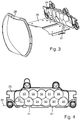
- Figure 3 shows a perspective view of some components of an embodiment of a light module according to the invention.
- the light from a light source is coupled into exactly one optical attachment that is structurally assigned to this light source.
- the light sources are in the for the Figure 3 selected representation behind the drawing plane and are therefore covered by the auxiliary optics of the primary optics.
- the arrangement of the light source and the associated lens attachment corresponds to that with reference to Figure 2 explained arrangement, but only some of the auxiliary optics Figure 3 have the bulge shown in the figure.
- two ancillary optics have an additional surface 61, each of which corresponds to the light exit surface 16 of the in connection with the Figure 2 illustrated bulge 23 corresponds and which serves to direct light into the overhead area. Since the bulges are each implemented as elevations from the rest of the ancillary optics, the light exit surfaces 16, 61 represent additional areas which enlarge the light exit surfaces 17 of the remaining ancillary optics, which are present without such bulges 23. At this additional light exit surface 61, light emerges which is directed under the screen 26 and in this way illuminates the overhead area 12, as described in detail with reference to FIG Figure 1 was explained.
- n can also be not equal to 11 and that n depends in particular on the magnitude of the luminous fluxes of the light sources. The greater the luminous flux of a single light source, the smaller n can be.
- Figure 3 also shows that the n light sources and their n optical attachments are arranged on a mounting support, the fastening elements, here tabs provided with recesses.
- This complex light source is the subject of Figures 3 and 4 a low beam complex light source.
- the complex light source can be fastened to frame structures of the light module and / or a screen assembly and / or a secondary optics assembly, so that a defined arrangement of these components results in relation to one another.
- FIG. 13 shows a view of a light-emitting front side of an arrangement of front optics of the exemplary embodiment from FIG Fig. 3.
- Figure 4 shows in detail the ancillary optics 29 with the light exit areas 42,51,52,53,54,55,56,57,58,59,62 of the 11 individual ancillary optics.
- the light exit surfaces 42 and 62 of two ancillary optics are designed in such a way that they have additional surfaces 41 and 61 which are the light exit surfaces of bulges 23 and with which light is directed under the diaphragm 26.
- auxiliary optics can have a bulge 23. This also depends on the solid angle that a single bulge takes out of the low beam of the light sources and directs into the overhead area. However, embodiments with two or more bulges are preferred, at least one of which is arranged on the right and at least one on the left of a central optical attachment.
- a central attachment lens is understood to mean an attachment lens that is used in a Intended use of the light module is cut from a plane that is spanned by the optical axis of the secondary optics and a vertical. This facilitates homogeneous illumination of the overhead area, since it is wider in the horizontal direction than in the vertical direction.
- the decentralized arrangement of two bulges prevents the overhead light bundle from being removed from the part of the light bundle of the light source with which the center of the light distribution is illuminated. This is advantageous because a light intensity maximum of the low beam distribution is desired in the middle.
- At least one ancillary optics has a bulge which is configured to deflect part of the light emanating from the light source so that it passes the diaphragm on a second side of the diaphragm and from the secondary optics in a second beam path in an area lying on a second side of the light-dark boundary in the second light distribution is distributed, this bulge lying to the left or right of a plane that is spanned by the optical axis of the secondary optics and a vertical.
- the additional surfaces 41 and 61 correspond to those in connection with FIG Figure 2 explained light exit surface 16.
- these additional partial areas of the respective light exit areas of the auxiliary optics lie below the aperture 26, while the other light exit areas 51-59 lie above the aperture 26. Due to the proportions of the areas 41, 61 to the other light exit areas, it is also evident that the vast majority of the light enters the area is steered above the aperture. As a first approximation, the respective light component can be assumed to be proportional to the respective light exit area.
- FIG. 11 shows a view of a rear side of the arrangement of front optics of the exemplary embodiment from FIG Figure 3 .
- the central parts 81,82,83,84,85,86,87,88,89,45,64 of the light entry surfaces of the directly imaging part of the individual ancillary optics are visible, the side surfaces 71,72,73,74,75,76, 77,78,79,43,63 of the non-direct imaging part of the ancillary optics, on which total internal reflections occur, and also reflective surfaces 45,65, which direct light under the diaphragm and thus the internally totally reflective interface of the bulge 23 from the Figure 2 correspond.
- the directly imaging part corresponds to the part of the ancillary optics that acts optically as a lens.
- the indirect imaging part corresponds to the part of the ancillary optics, at the boundary surface of which there are additional internal total reflections.
- the solution described is particularly advantageous for light modules with which both a low beam distribution and a high beam distribution are to be generated.
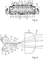
- Figure 6 shows a side view of such a light module 40 as a further embodiment of a light module according to the invention.
- Fig. 6 shows in particular beam paths 31, 32.1, 32.2 of the low beam portion, a beam path 33 of the overhead light portion and beam paths 101, 102, 103 of an additional portion serving to generate a high beam light distribution.
- the high beam component is compared with the subject of Figure 2 additional light sources 91 and ancillary optics 92 generated.
- the light sources 91 are preferably likewise semiconductor light sources, in particular light-emitting diodes.
- the auxiliary optics 92 are preferably also transparent solid bodies with a central part acting as a lens and side surfaces on which concentrating internal total reflections take place.
- the light entry surface is also preferably divided into a central part and peripheral parts, as is the case with the object of Fig. 2 was explained.
- the ancillary optics 92 involved in generating a high-beam portion above the light-dark boundary of the second light distribution do not have any bulges that direct light past a different side of the diaphragm 26 than is done by the rest of the respective ancillary optics.
- the optical attachment 92 directs all of the light coupled in from its structurally associated light source 91 past the second side 20 of the diaphragm 26. This is illustrated by the beam paths 101, 102 and 103.
- the second side is the lower side of the panel, which also corresponds to the arrangement when the light module is used as intended.
- this light illuminates above the cut-off line in the Fig. 1 lying areas.
- the intensity of the in these Light propagating beam paths is significantly greater than the intensity of the overhead light propagating in beam path 33, so that the brightness resulting from the overhead light is completely outshone by the brightness generated by the light sources 91.
- Figure 7 shows a perspective view of some components of a light module set up to generate a low beam portion, an overhead light portion and a high beam portion.
- the light module according to Fig. 7 is based on the light module of Figure 3 and, like this, has a low-beam complex light source, a diaphragm and secondary optics in the form of a projection lens.
- the explanations for Figure 3 also for the subject of Figure 7 .
- the subject of the Fig. 7 an additional assembly that serves as a complex light source 110 for an additional light distribution.
- the additional light distribution lies above the horizon and thus supplements the low beam distribution, which is essentially below the horizon, to form a high beam distribution.
- the complex light source 110 like the complex light source according to FIG Figure 3 , Fastening structures on. These are like the fastening structures of the object of Figure 3 preferably shaped in such a way that the two complex light sources can be connected to form a coherent and inherently rigid assembly, so that an adjustment of the emission directions and an adjustment in the headlight can always take place together. With the fastening elements, the complex light source can be fastened to frame structures of the light module and / or a screen assembly and / or a secondary optics assembly, so that a defined arrangement of these components results in relation to one another.
- the modular structure also enables cost-effective production, because, for example, for light modules that only have to produce a low beam distribution (and an overhead light distribution, but not a high beam distribution) and for light modules which are also to produce a high beam distribution, the same assemblies in the form of the low beam complex light source , bezel assembly, and secondary optics.
- FIG. 13 shows a view of a light-emitting front side of an arrangement of primary optics of the exemplary embodiment from FIG Figure 7 .
- a light module that is intended to generate a high beam distribution in addition to a low beam distribution if the overhead light is generated by an additional diaphragm between the diaphragm and the secondary lens.
- the disadvantage results from the fact that such an additional screen would at least partially block the light path for the high beam.
- a light module according to the invention is characterized in that the lower edge of the low beam directs light under the diaphragm 26 at the points where the low beam front lens 29 with the help of surfaces 41 and 61, i.e. with the help of the light exit surfaces of bulges of the front lens, directs light under the diaphragm 26 -Front optics and the upper edge of the high-beam headlight lens have a sufficient distance 130 from each other, as shown in the Fig. 8 is shown.
- this condition was met by the fact that the front optics 122, 123 of the high beam assembly, which are arranged below the front optics of the low beam assembly having additional bulges 23, are smaller than a central front optics of the high beam assembly that is located between the front optics 122, 123 of High beam assembly lies.
Claims (13)
- Module d'éclairage (14) pour phare de véhicule automobile, comportant au moins une première source de lumière (21), une optique primaire (25), un diaphragme (26) et une optique secondaire (28), dans lequel l'optique primaire est conçue pour transférer de la lumière issue de la source de lumière dans une répartition de lumière intermédiaire entre l'optique primaire et l'optique secondaire, dans lequel le diaphragme présente un bord extérieur cohérent et une surface de diaphragme qui fait saillie dans la répartition de lumière intermédiaire et qui est délimitée par un bord de diaphragme (27), et dans lequel le diaphragme est agencé par rapport à l'optique secondaire de sorte que le bord du diaphragme est représenté par l'optique secondaire sous la forme d'une limite clair-sombre (13) dans une seconde répartition de lumière, qui est générée par l'optique secondaire en amont du module d'éclairage sous la forme d'une image de la répartition de lumière intermédiaire, et dans lequel l'optique primaire est agencée par rapport à l'optique secondaire de telle sorte que l'optique secondaire répartit la lumière de la répartition de lumière intermédiaire, qui passe au niveau du diaphragme sur un premier côté du diaphragme, selon un premier trajet de faisceau (31, 32) dans une zone (11) située sur un premier côté de la limite clair-sombre de la seconde répartition de lumière, dans lequel l'optique primaire est conçue pour dévier une partie de la lumière issue de la source de lumière de telle sorte qu'elle passe sur un second côté (20) du diaphragme à l'extérieur du diaphragme et est distribuée par l'optique secondaire selon un second trajet de faisceau (33) dans une zone située sur un second côté (20) de la limite clair-sombre dans la seconde répartition de lumière, caractérisé en ce que l'optique primaire présente une surface d'entrée de lumière (19) ayant une pluralité de surfaces partielles (18, 19), une surface de sortie de lumière (17) et une surface latérale de déviation de lumière (24, 22) et un renflement (15) dans sa surface latérale, le renflement (15) se trouvant dans une partie de la surface latérale d'une optique additionnelle, qui fait face au même côté que le second côté (20) du diaphragme (26), le renflement (15) étant conçu de sorte que la partie de la lumière issue de la source de lumière qui passe à l'extérieur du diaphragme sur le second côté (20) du diaphragme (26), est distribuée par l'optique secondaire (28) selon le second trajet de faisceau (33) dans la zone située sur le second côté de la limite clair-sombre dans la seconde répartition de lumière.
- Module d'éclairage (14) selon la revendication 1, caractérisé en ce que la source de lumière (21) est une source de lumière à semi-conducteurs, notamment une diode électroluminescente, montée sur un support de montage ou une carte de circuit imprimé.
- Module d'éclairage (14) selon l'une des revendications précédentes, caractérisé en ce qu'un premier côté du diaphragme (26) ou les deux côtés du diaphragme sont réalisés sous la forme d'une surface réfléchissante.
- Module d'éclairage (14) selon l'une des revendications précédentes, caractérisé en ce que la surface d'entrée de lumière (19) présente une partie centrale et des parties périphériques adjacentes à la partie centrale, et en ce que la source de lumière (21) et les différentes parties (18, 19) de la surface d'entrée de lumière sont agencées les unes par rapport aux autres de telle sorte que la lumière subit divers changements de direction lors de son passage à travers l'optique primaire (25), qui sont provoqués par la réfraction et la réflexion.
- Module d'éclairage (14) selon la revendication 4, caractérisé en ce que la lumière dont le trajet s'étend sur le premier côté du diaphragme subit une réfraction lors de l'entrée de lumière, qui se produit via la partie périphérique (18) de la surface d'entrée de lumière, subit une réflexion totale interne sur une surface latérale (24) et subit une réfraction lors de la sortie de la lumière via la surface de sortie de lumière (17).
- Module d'éclairage (14) selon la revendication 4, caractérisé en ce que l'optique primaire est conçue pour permettre à la lumière qui entre dans l'optique primaire (25) via la partie centrale (19) de la surface d'entrée de lumière d'atteindre la surface de sortie de lumière (17) directement sans réflexion sur une paroi latérale.
- Module d'éclairage (14) selon l'une des revendications précédentes, caractérisé en ce que le renflement (15) est monobloc avec le reste de l'optique primaire et fait saillie en élévation par rapport à la surface latérale de l'optique primaire restante et est délimité par une surface latérale de renflement (23) et une surface de sortie de lumière de renflement (16).
- Module d'éclairage (14) selon l'une des revendications précédentes, caractérisé en ce que le renflement (15) se situe dans une partie de la surface latérale de l'optique primaire qui est plus proche de la surface de sortie de lumière (17) de l'optique primaire que de la surface d'entrée de lumière.
- Module d'éclairage (14) selon l'une des revendications précédentes, caractérisé en ce que le renflement (15) a une surface de sortie de lumière de renflement (16) qui jouxte la surface de sortie de lumière restante (17) de l'optique primaire (25), la transition de la surface de sortie de lumière de renflement (16) vers la surface de sortie de lumière restante (17) se faisant sans coude.
- Module d'éclairage (14) selon la revendication 7, caractérisé en ce que la surface latérale de renflement (23) et la surface de sortie de lumière de renflement (16) sont agencées en référence à leur orientation par rapport à la lumière incidente sur la surface latérale de renflement (23), de sorte qu'elle dirige au moins un partie de cette lumière sur le second côté du diaphragme le long du diaphragme sur l'optique secondaire.
- Module d'éclairage (14) selon la revendication 7, caractérisé en ce que le renflement (15) et sa surface de sortie de lumière de renflement (16) sont conçus de telle sorte qu'une zone surélevée (12) de la répartition de lumière est éclairée par la lumière sortant de la surface de sortie de lumière de renflement (16).
- Module d'éclairage (14) selon l'une des revendications précédentes, caractérisé en ce que les renflements sont réalisés chacun sous la forme d'éminences par rapport à l'optique primaire restante (25).
- Module d'éclairage (14) selon l'une des revendications précédentes, caractérisé en ce que le renflement (15) se trouve à gauche ou à droite d'un plan qui est délimité par l'axe optique de l'optique secondaire et une verticale.
Applications Claiming Priority (1)
| Application Number | Priority Date | Filing Date | Title |
|---|---|---|---|
| DE102013207850.1A DE102013207850A1 (de) | 2013-04-29 | 2013-04-29 | Lichtmodul für einen Kraftfahrzeugscheinwerfer |
Publications (3)
| Publication Number | Publication Date |
|---|---|
| EP2799761A2 EP2799761A2 (fr) | 2014-11-05 |
| EP2799761A3 EP2799761A3 (fr) | 2016-08-31 |
| EP2799761B1 true EP2799761B1 (fr) | 2020-10-14 |
Family
ID=50289534
Family Applications (1)
| Application Number | Title | Priority Date | Filing Date |
|---|---|---|---|
| EP14160613.7A Active EP2799761B1 (fr) | 2013-04-29 | 2014-03-19 | Module d'éclairage de phare de véhicule automobile |
Country Status (4)
| Country | Link |
|---|---|
| US (1) | US9249943B2 (fr) |
| EP (1) | EP2799761B1 (fr) |
| CN (1) | CN104121535B (fr) |
| DE (1) | DE102013207850A1 (fr) |
Families Citing this family (38)
| Publication number | Priority date | Publication date | Assignee | Title |
|---|---|---|---|---|
| JP6322931B2 (ja) | 2013-08-29 | 2018-05-16 | 市光工業株式会社 | 車両用灯具 |
| JP6331797B2 (ja) * | 2014-07-14 | 2018-05-30 | ウシオ電機株式会社 | 車載用光源装置 |
| DE102014019344A1 (de) * | 2014-12-22 | 2016-06-23 | GM Global Technology Operations LLC (n. d. Ges. d. Staates Delaware) | Kraftfahrzeugscheinwerfer, Kraftfahrzeugscheinwerfersystem, Kraftfahrzeug sowie Verfahren zum Betrieb eines Kraftfahrzeugs |
| CN104849844A (zh) * | 2015-03-19 | 2015-08-19 | 浙江大学 | 碟式菲涅尔反射聚光方法及其装置 |
| CN107960117B (zh) * | 2015-05-22 | 2021-01-12 | 三菱电机株式会社 | 前照灯模块及前照灯装置 |
| AT517752B1 (de) * | 2015-09-17 | 2018-04-15 | Zkw Group Gmbh | Lichtmodul für einen kraftfahrzeugscheinwerfer zur abstrahlung einer langreichweitigen lichtverteilung sowie beleuchtungsvorrichtung |
| CN105258057B (zh) * | 2015-11-03 | 2017-11-03 | 西安睿莱特汽车科技有限公司 | 一种led车用大灯 |
| CN105276487A (zh) * | 2015-11-25 | 2016-01-27 | 海盐丽光电子科技有限公司 | 一种远近光一体的led汽车透镜 |
| AT518083B1 (de) * | 2015-12-22 | 2017-07-15 | Zkw Group Gmbh | Scheinwerfer für Fahrzeuge mit zumindest einem Laser-Lichtmodul |
| FR3048065B1 (fr) * | 2016-02-23 | 2019-11-29 | Valeo Vision | Module et dispositif d'eclairage a encombrement reduit pour vehicule automobile |
| JP6709654B2 (ja) | 2016-03-25 | 2020-06-17 | 株式会社小糸製作所 | 車両用灯具、および当該車両用灯具を備えた車両 |
| CN106195665A (zh) * | 2016-08-24 | 2016-12-07 | 常州星宇车灯股份有限公司 | 多颗粒led双光透镜模组 |
| DE102016217121A1 (de) * | 2016-09-08 | 2018-03-08 | Osram Gmbh | Optik und optisches System |
| CN106439680A (zh) * | 2016-09-29 | 2017-02-22 | 马瑞利汽车零部件(芜湖)有限公司 | 一种形成近光光型的透镜 |
| JP6980377B2 (ja) * | 2016-12-15 | 2021-12-15 | 株式会社小糸製作所 | 車両用前照灯 |
| DE102017110876A1 (de) * | 2017-05-18 | 2018-11-22 | Automotive Lighting Reutlingen Gmbh | Lichtmodul eines Kraftfahrzeugscheinwerfers und Kraftfahrzeugscheinwerfer mit einem solchen Lichtmodul |
| CN107763566A (zh) * | 2017-11-22 | 2018-03-06 | 上海小糸车灯有限公司 | 一种反射式车灯单元 |
| EP3495718A1 (fr) * | 2017-12-05 | 2019-06-12 | ZKW Group GmbH | Dispositif de projection pour un phare de véhicule automobile |
| FR3075928B1 (fr) * | 2017-12-22 | 2021-06-25 | Valeo Vision | Module lumineux pour projecteur de vehicule |
| DE102018108567A1 (de) * | 2018-04-11 | 2019-10-17 | HELLA GmbH & Co. KGaA | Scheinwerfer für Fahrzeuge |
| CN110454747A (zh) * | 2018-05-07 | 2019-11-15 | 欧司朗有限公司 | 照明装置 |
| JP7269025B2 (ja) * | 2019-02-12 | 2023-05-08 | 株式会社小糸製作所 | 車両用灯具 |
| WO2020173444A1 (fr) * | 2019-02-25 | 2020-09-03 | 华域视觉科技(上海)有限公司 | Dispositif d'éclairage de lampe de véhicule intégré de feux de route et de croisement, lampe de véhicule et véhicule |
| DE102019104722A1 (de) * | 2019-02-25 | 2020-08-27 | Automotive Lighting Reutlingen Gmbh | Scheinwerfer mit einer Mehrzahl von Halbleiterlichtquellen und einem einstückigen Primäroptikfeld |
| CN110220158B (zh) * | 2019-05-20 | 2020-04-21 | 华域视觉科技(上海)有限公司 | 车灯用光学装置、汽车照明装置及汽车 |
| CN110186008A (zh) * | 2019-06-05 | 2019-08-30 | 华域视觉科技(上海)有限公司 | 车辆照明单元及车辆照明车灯 |
| DE102019118968A1 (de) | 2019-07-12 | 2021-01-14 | HELLA GmbH & Co. KGaA | Projektionsscheinwerfer für Fahrzeuge |
| EP3839324A1 (fr) * | 2019-12-16 | 2021-06-23 | ZKW Group GmbH | Dispositif d'éclairage pour un phare de véhicule automobile |
| EP3839327A1 (fr) * | 2019-12-20 | 2021-06-23 | ZKW Group GmbH | Module de projection pour un phare de véhicule automobile |
| KR20210083600A (ko) * | 2019-12-27 | 2021-07-07 | 에스엘 주식회사 | 차량용 램프 |
| CN113124375A (zh) * | 2020-01-15 | 2021-07-16 | 华域视觉科技(上海)有限公司 | 车辆照明装置、车灯以及车辆 |
| CN211694701U (zh) * | 2020-01-20 | 2020-10-16 | 华域视觉科技(上海)有限公司 | 前照灯光学元件、前照灯模组、车灯及车辆 |
| CN113137585A (zh) | 2020-01-20 | 2021-07-20 | 华域视觉科技(上海)有限公司 | 前照灯光学元件、车灯模组、车灯及车辆 |
| EP3971471B1 (fr) * | 2020-09-21 | 2024-01-03 | ZKW Group GmbH | Dispositif d'éclairage pour un projecteur de véhicule automobile permettant de créer une distribution de lumière de base comprenant un faisceau d'illumination des panneaux |
| FR3125860B1 (fr) * | 2021-07-30 | 2023-08-04 | Valeo Vision | Module d’eclairage bi-led avec piece optique transparente mince |
| DE102021130506A1 (de) | 2021-11-22 | 2023-05-25 | Marelli Automotive Lighting Reutlingen (Germany) GmbH | Lichtmodul für einen Kraftfahrzeugscheinwerfer und Befestigung von Bauteilen des Lichtmoduls |
| DE102022111039A1 (de) | 2022-05-04 | 2023-11-09 | Marelli Automotive Lighting Reutlingen (Germany) GmbH | Lichtmodul mit mehreren Vorsatzoptiken |
| CN115435293B (zh) * | 2022-10-27 | 2023-03-24 | 常州星宇车灯股份有限公司 | 聚光效果好的厚壁光学模组及车灯系统 |
Family Cites Families (16)
| Publication number | Priority date | Publication date | Assignee | Title |
|---|---|---|---|---|
| DE4315401A1 (de) | 1993-05-08 | 1994-11-10 | Bosch Gmbh Robert | Scheinwerfer für Fahrzeuge |
| JP3798723B2 (ja) | 2002-04-08 | 2006-07-19 | 株式会社小糸製作所 | 車両用前照灯 |
| FR2853394B1 (fr) | 2003-04-03 | 2006-03-10 | Valeo Vision | Dispositif de projection pour vehicule automobile eclairant des points de portique |
| JP4579154B2 (ja) * | 2005-12-28 | 2010-11-10 | 株式会社小糸製作所 | 車両用前照灯 |
| JP4749968B2 (ja) * | 2006-07-31 | 2011-08-17 | 株式会社小糸製作所 | 車両用前照灯 |
| JP2008226707A (ja) * | 2007-03-14 | 2008-09-25 | Koito Mfg Co Ltd | 車両用灯具 |
| JP4782064B2 (ja) | 2007-04-10 | 2011-09-28 | 株式会社小糸製作所 | 車両用灯具ユニット |
| TW200950996A (en) | 2008-06-06 | 2009-12-16 | Tyc Brother Ind Co Ltd | Vehicle headlight capable of compensating for light intensity of ark region |
| DE102008036192B4 (de) | 2008-08-02 | 2012-05-03 | Automotive Lighting Reutlingen Gmbh | Kraftfahrzeugbeleuchtungseinrichtung |
| DE102009020593B4 (de) | 2009-05-09 | 2017-08-17 | Automotive Lighting Reutlingen Gmbh | Zur Erzeugung einer definierten Overhead-Beleuchtung eingerichteter Fahrzeugscheinwerfer |
| JP5305100B2 (ja) * | 2009-06-04 | 2013-10-02 | スタンレー電気株式会社 | 車両用灯具 |
| JP5535663B2 (ja) * | 2010-01-14 | 2014-07-02 | 株式会社小糸製作所 | 車両用ヘッドランプ |
| DE102010023177A1 (de) * | 2010-06-09 | 2011-12-15 | Automotive Lighting Reutlingen Gmbh | Lichtmodul für eine Beleuchtungseinrichtung eines Kraftfahrzeugs |
| DE102011004569A1 (de) | 2011-02-23 | 2012-08-23 | Automotive Lighting Reutlingen Gmbh | Zum Einbau in einem Kraftfahrzeug vorgesehene Beleuchtungseinrichtung |
| DE102011013211B4 (de) * | 2011-03-05 | 2012-12-06 | Automotive Lighting Reutlingen Gmbh | Kraftfahrzeugscheinwerfer mit einem Mehrfunktions-Projektionsmodul |
| JP2012216408A (ja) * | 2011-03-31 | 2012-11-08 | Ichikoh Ind Ltd | 車両用前照灯 |
-
2013
- 2013-04-29 DE DE102013207850.1A patent/DE102013207850A1/de not_active Withdrawn
-
2014
- 2014-03-19 EP EP14160613.7A patent/EP2799761B1/fr active Active
- 2014-04-22 US US14/258,115 patent/US9249943B2/en active Active
- 2014-04-28 CN CN201410175764.4A patent/CN104121535B/zh active Active
Non-Patent Citations (1)
| Title |
|---|
| None * |
Also Published As
| Publication number | Publication date |
|---|---|
| CN104121535A (zh) | 2014-10-29 |
| US9249943B2 (en) | 2016-02-02 |
| CN104121535B (zh) | 2018-06-12 |
| EP2799761A3 (fr) | 2016-08-31 |
| DE102013207850A1 (de) | 2014-10-30 |
| US20140321143A1 (en) | 2014-10-30 |
| EP2799761A2 (fr) | 2014-11-05 |
Similar Documents
| Publication | Publication Date | Title |
|---|---|---|
| EP2799761B1 (fr) | Module d'éclairage de phare de véhicule automobile | |
| EP2910847B1 (fr) | Module d'éclairage d'un projecteur de véhicule automobile et projecteur avec un tel module d'éclairage | |
| DE102009053581B3 (de) | Lichtmodul für eine Beleuchtungseinrichtung eines Kraftfahrzeugs | |
| DE102014205994B4 (de) | Lichtmodul mit Halbleiterlichtquelle und Vorsatzoptik und Kraftfahrzeugscheinwerfer mit einem solchen Lichtmodul | |
| EP2799762B1 (fr) | Module d'éclairage de phare de véhicule automobile | |
| DE102009037698A1 (de) | Fahrzeugbeleuchtungseinheit und Fahrzeugleuchte | |
| DE102011078653B4 (de) | Vorsatzoptik zur Bündelung von ausgesandtem Licht mindestens einer Halbleiterlichtquelle | |
| DE102014200368B4 (de) | Teilfernlicht-Projektionslichtmodul für einen Kraftfahrzeugscheinwerfer | |
| AT518551B1 (de) | Kraftfahrzeugbeleuchtungsvorrichtung | |
| WO2011154470A1 (fr) | Accessoire optique constitué d'un matériau transparent pour la focalisation de lumière, ensemble de lentilles comportant au moins un tel accessoire optique, et module de lumière doté d'un tel ensemble de lentilles | |
| EP2789901A2 (fr) | Module d'éclairage pour un dispositif d'éclairage de véhicule automobile | |
| EP2730836B1 (fr) | Module d'éclairage pour un phare de véhicule automobile | |
| EP2523022A1 (fr) | Module d'éclairage pour un phare de véhicule automobile destiné à la production d'une distribution lumineuse variable et phare de véhicule automobile doté d'un tel module d'éclairage | |
| EP2984396A2 (fr) | Unité lumineuse dotée d'un cache pourvu d'au moins une fenêtre optique | |
| WO2019233953A1 (fr) | Phare de véhicule à moteur comprenant au moins deux modules d'éclairage | |
| DE102017107781A1 (de) | Primäroptikeinheit für ein Lichtmodul | |
| EP3301350A1 (fr) | Module d'éclairage pour phare de véhicule automobile | |
| DE102018105720B4 (de) | Lichtmodul für Kraftfahrzeugscheinwerfer | |
| DE112017006796B4 (de) | Transparenter fotoleiter mit lichtabschirmfunktion und anwendung dafür | |
| DE102015204735B4 (de) | Lichtleiterelement einer Kraftfahrzeug-Beleuchtungseinrichtung und Kraftfahrzeug-Beleuchtungseinrichtung mit einem solchen Lichtleiterelement | |
| DE102021125141A1 (de) | Leuchte für ein fahrzeug | |
| DE102012215124A1 (de) | Beleuchtungseinrichtung mit Lichtquelle, Lichtleitkörper und Reflektor | |
| AT519356B1 (de) | Lichtmodul für einen Kraftfahrzeugscheinwerfer | |
| DE102015201856A1 (de) | Kfz-Scheinwerfer | |
| EP3719391B1 (fr) | Module de feu de route partiel pour un phare de véhicule automobile |
Legal Events
| Date | Code | Title | Description |
|---|---|---|---|
| PUAI | Public reference made under article 153(3) epc to a published international application that has entered the european phase |
Free format text: ORIGINAL CODE: 0009012 |
|
| 17P | Request for examination filed |
Effective date: 20140319 |
|
| AK | Designated contracting states |
Kind code of ref document: A2 Designated state(s): AL AT BE BG CH CY CZ DE DK EE ES FI FR GB GR HR HU IE IS IT LI LT LU LV MC MK MT NL NO PL PT RO RS SE SI SK SM TR |
|
| AX | Request for extension of the european patent |
Extension state: BA ME |
|
| PUAL | Search report despatched |
Free format text: ORIGINAL CODE: 0009013 |
|
| AK | Designated contracting states |
Kind code of ref document: A3 Designated state(s): AL AT BE BG CH CY CZ DE DK EE ES FI FR GB GR HR HU IE IS IT LI LT LU LV MC MK MT NL NO PL PT RO RS SE SI SK SM TR |
|
| AX | Request for extension of the european patent |
Extension state: BA ME |
|
| RIC1 | Information provided on ipc code assigned before grant |
Ipc: F21S 8/10 20060101AFI20160728BHEP |
|
| STAA | Information on the status of an ep patent application or granted ep patent |
Free format text: STATUS: REQUEST FOR EXAMINATION WAS MADE |
|
| R17P | Request for examination filed (corrected) |
Effective date: 20170228 |
|
| RBV | Designated contracting states (corrected) |
Designated state(s): AL AT BE BG CH CY CZ DE DK EE ES FI FR GB GR HR HU IE IS IT LI LT LU LV MC MK MT NL NO PL PT RO RS SE SI SK SM TR |
|
| REG | Reference to a national code |
Ref country code: DE Ref legal event code: R079 Ref document number: 502014014874 Country of ref document: DE Free format text: PREVIOUS MAIN CLASS: F21S0008100000 Ipc: F21S0041147000 |
|
| GRAP | Despatch of communication of intention to grant a patent |
Free format text: ORIGINAL CODE: EPIDOSNIGR1 |
|
| STAA | Information on the status of an ep patent application or granted ep patent |
Free format text: STATUS: GRANT OF PATENT IS INTENDED |
|
| RIC1 | Information provided on ipc code assigned before grant |
Ipc: F21S 41/663 20180101ALI20191030BHEP Ipc: F21S 41/43 20180101ALI20191030BHEP Ipc: F21S 41/33 20180101ALI20191030BHEP Ipc: F21S 41/275 20180101ALI20191030BHEP Ipc: F21S 41/36 20180101ALI20191030BHEP Ipc: F21S 41/25 20180101ALI20191030BHEP Ipc: F21S 41/32 20180101ALI20191030BHEP Ipc: F21S 41/147 20180101AFI20191030BHEP |
|
| INTG | Intention to grant announced |
Effective date: 20191202 |
|
| GRAJ | Information related to disapproval of communication of intention to grant by the applicant or resumption of examination proceedings by the epo deleted |
Free format text: ORIGINAL CODE: EPIDOSDIGR1 |
|
| STAA | Information on the status of an ep patent application or granted ep patent |
Free format text: STATUS: REQUEST FOR EXAMINATION WAS MADE |
|
| GRAP | Despatch of communication of intention to grant a patent |
Free format text: ORIGINAL CODE: EPIDOSNIGR1 |
|
| STAA | Information on the status of an ep patent application or granted ep patent |
Free format text: STATUS: GRANT OF PATENT IS INTENDED |
|
| INTG | Intention to grant announced |
Effective date: 20200313 |
|
| GRAJ | Information related to disapproval of communication of intention to grant by the applicant or resumption of examination proceedings by the epo deleted |
Free format text: ORIGINAL CODE: EPIDOSDIGR1 |
|
| STAA | Information on the status of an ep patent application or granted ep patent |
Free format text: STATUS: REQUEST FOR EXAMINATION WAS MADE |
|
| GRAS | Grant fee paid |
Free format text: ORIGINAL CODE: EPIDOSNIGR3 |
|
| STAA | Information on the status of an ep patent application or granted ep patent |
Free format text: STATUS: GRANT OF PATENT IS INTENDED |
|
| GRAP | Despatch of communication of intention to grant a patent |
Free format text: ORIGINAL CODE: EPIDOSNIGR1 |
|
| INTC | Intention to grant announced (deleted) | ||
| INTG | Intention to grant announced |
Effective date: 20200811 |
|
| GRAA | (expected) grant |
Free format text: ORIGINAL CODE: 0009210 |
|
| STAA | Information on the status of an ep patent application or granted ep patent |
Free format text: STATUS: THE PATENT HAS BEEN GRANTED |
|
| AK | Designated contracting states |
Kind code of ref document: B1 Designated state(s): AL AT BE BG CH CY CZ DE DK EE ES FI FR GB GR HR HU IE IS IT LI LT LU LV MC MK MT NL NO PL PT RO RS SE SI SK SM TR |
|
| REG | Reference to a national code |
Ref country code: GB Ref legal event code: FG4D Free format text: NOT ENGLISH |
|
| REG | Reference to a national code |
Ref country code: AT Ref legal event code: REF Ref document number: 1323938 Country of ref document: AT Kind code of ref document: T Effective date: 20201015 Ref country code: CH Ref legal event code: EP |
|
| REG | Reference to a national code |
Ref country code: DE Ref legal event code: R096 Ref document number: 502014014874 Country of ref document: DE |
|
| REG | Reference to a national code |
Ref country code: IE Ref legal event code: FG4D Free format text: LANGUAGE OF EP DOCUMENT: GERMAN |
|
| REG | Reference to a national code |
Ref country code: NL Ref legal event code: MP Effective date: 20201014 |
|
| PG25 | Lapsed in a contracting state [announced via postgrant information from national office to epo] |
Ref country code: FI Free format text: LAPSE BECAUSE OF FAILURE TO SUBMIT A TRANSLATION OF THE DESCRIPTION OR TO PAY THE FEE WITHIN THE PRESCRIBED TIME-LIMIT Effective date: 20201014 Ref country code: RS Free format text: LAPSE BECAUSE OF FAILURE TO SUBMIT A TRANSLATION OF THE DESCRIPTION OR TO PAY THE FEE WITHIN THE PRESCRIBED TIME-LIMIT Effective date: 20201014 Ref country code: NL Free format text: LAPSE BECAUSE OF FAILURE TO SUBMIT A TRANSLATION OF THE DESCRIPTION OR TO PAY THE FEE WITHIN THE PRESCRIBED TIME-LIMIT Effective date: 20201014 Ref country code: PT Free format text: LAPSE BECAUSE OF FAILURE TO SUBMIT A TRANSLATION OF THE DESCRIPTION OR TO PAY THE FEE WITHIN THE PRESCRIBED TIME-LIMIT Effective date: 20210215 Ref country code: NO Free format text: LAPSE BECAUSE OF FAILURE TO SUBMIT A TRANSLATION OF THE DESCRIPTION OR TO PAY THE FEE WITHIN THE PRESCRIBED TIME-LIMIT Effective date: 20210114 Ref country code: GR Free format text: LAPSE BECAUSE OF FAILURE TO SUBMIT A TRANSLATION OF THE DESCRIPTION OR TO PAY THE FEE WITHIN THE PRESCRIBED TIME-LIMIT Effective date: 20210115 |
|
| REG | Reference to a national code |
Ref country code: LT Ref legal event code: MG4D |
|
| PG25 | Lapsed in a contracting state [announced via postgrant information from national office to epo] |
Ref country code: ES Free format text: LAPSE BECAUSE OF FAILURE TO SUBMIT A TRANSLATION OF THE DESCRIPTION OR TO PAY THE FEE WITHIN THE PRESCRIBED TIME-LIMIT Effective date: 20201014 Ref country code: BG Free format text: LAPSE BECAUSE OF FAILURE TO SUBMIT A TRANSLATION OF THE DESCRIPTION OR TO PAY THE FEE WITHIN THE PRESCRIBED TIME-LIMIT Effective date: 20210114 Ref country code: LV Free format text: LAPSE BECAUSE OF FAILURE TO SUBMIT A TRANSLATION OF THE DESCRIPTION OR TO PAY THE FEE WITHIN THE PRESCRIBED TIME-LIMIT Effective date: 20201014 Ref country code: IS Free format text: LAPSE BECAUSE OF FAILURE TO SUBMIT A TRANSLATION OF THE DESCRIPTION OR TO PAY THE FEE WITHIN THE PRESCRIBED TIME-LIMIT Effective date: 20210214 Ref country code: SE Free format text: LAPSE BECAUSE OF FAILURE TO SUBMIT A TRANSLATION OF THE DESCRIPTION OR TO PAY THE FEE WITHIN THE PRESCRIBED TIME-LIMIT Effective date: 20201014 Ref country code: PL Free format text: LAPSE BECAUSE OF FAILURE TO SUBMIT A TRANSLATION OF THE DESCRIPTION OR TO PAY THE FEE WITHIN THE PRESCRIBED TIME-LIMIT Effective date: 20201014 |
|
| PG25 | Lapsed in a contracting state [announced via postgrant information from national office to epo] |
Ref country code: HR Free format text: LAPSE BECAUSE OF FAILURE TO SUBMIT A TRANSLATION OF THE DESCRIPTION OR TO PAY THE FEE WITHIN THE PRESCRIBED TIME-LIMIT Effective date: 20201014 |
|
| REG | Reference to a national code |
Ref country code: DE Ref legal event code: R097 Ref document number: 502014014874 Country of ref document: DE |
|
| PG25 | Lapsed in a contracting state [announced via postgrant information from national office to epo] |
Ref country code: SK Free format text: LAPSE BECAUSE OF FAILURE TO SUBMIT A TRANSLATION OF THE DESCRIPTION OR TO PAY THE FEE WITHIN THE PRESCRIBED TIME-LIMIT Effective date: 20201014 Ref country code: RO Free format text: LAPSE BECAUSE OF FAILURE TO SUBMIT A TRANSLATION OF THE DESCRIPTION OR TO PAY THE FEE WITHIN THE PRESCRIBED TIME-LIMIT Effective date: 20201014 Ref country code: LT Free format text: LAPSE BECAUSE OF FAILURE TO SUBMIT A TRANSLATION OF THE DESCRIPTION OR TO PAY THE FEE WITHIN THE PRESCRIBED TIME-LIMIT Effective date: 20201014 Ref country code: EE Free format text: LAPSE BECAUSE OF FAILURE TO SUBMIT A TRANSLATION OF THE DESCRIPTION OR TO PAY THE FEE WITHIN THE PRESCRIBED TIME-LIMIT Effective date: 20201014 Ref country code: CZ Free format text: LAPSE BECAUSE OF FAILURE TO SUBMIT A TRANSLATION OF THE DESCRIPTION OR TO PAY THE FEE WITHIN THE PRESCRIBED TIME-LIMIT Effective date: 20201014 Ref country code: SM Free format text: LAPSE BECAUSE OF FAILURE TO SUBMIT A TRANSLATION OF THE DESCRIPTION OR TO PAY THE FEE WITHIN THE PRESCRIBED TIME-LIMIT Effective date: 20201014 |
|
| PLBE | No opposition filed within time limit |
Free format text: ORIGINAL CODE: 0009261 |
|
| STAA | Information on the status of an ep patent application or granted ep patent |
Free format text: STATUS: NO OPPOSITION FILED WITHIN TIME LIMIT |
|
| PG25 | Lapsed in a contracting state [announced via postgrant information from national office to epo] |
Ref country code: DK Free format text: LAPSE BECAUSE OF FAILURE TO SUBMIT A TRANSLATION OF THE DESCRIPTION OR TO PAY THE FEE WITHIN THE PRESCRIBED TIME-LIMIT Effective date: 20201014 |
|
| 26N | No opposition filed |
Effective date: 20210715 |
|
| PG25 | Lapsed in a contracting state [announced via postgrant information from national office to epo] |
Ref country code: MC Free format text: LAPSE BECAUSE OF FAILURE TO SUBMIT A TRANSLATION OF THE DESCRIPTION OR TO PAY THE FEE WITHIN THE PRESCRIBED TIME-LIMIT Effective date: 20201014 Ref country code: AL Free format text: LAPSE BECAUSE OF FAILURE TO SUBMIT A TRANSLATION OF THE DESCRIPTION OR TO PAY THE FEE WITHIN THE PRESCRIBED TIME-LIMIT Effective date: 20201014 Ref country code: IT Free format text: LAPSE BECAUSE OF FAILURE TO SUBMIT A TRANSLATION OF THE DESCRIPTION OR TO PAY THE FEE WITHIN THE PRESCRIBED TIME-LIMIT Effective date: 20201014 |
|
| REG | Reference to a national code |
Ref country code: CH Ref legal event code: PL |
|
| GBPC | Gb: european patent ceased through non-payment of renewal fee |
Effective date: 20210319 |
|
| PG25 | Lapsed in a contracting state [announced via postgrant information from national office to epo] |
Ref country code: SI Free format text: LAPSE BECAUSE OF FAILURE TO SUBMIT A TRANSLATION OF THE DESCRIPTION OR TO PAY THE FEE WITHIN THE PRESCRIBED TIME-LIMIT Effective date: 20201014 |
|
| REG | Reference to a national code |
Ref country code: BE Ref legal event code: MM Effective date: 20210331 |
|
| PG25 | Lapsed in a contracting state [announced via postgrant information from national office to epo] |
Ref country code: CH Free format text: LAPSE BECAUSE OF NON-PAYMENT OF DUE FEES Effective date: 20210331 Ref country code: LU Free format text: LAPSE BECAUSE OF NON-PAYMENT OF DUE FEES Effective date: 20210319 Ref country code: LI Free format text: LAPSE BECAUSE OF NON-PAYMENT OF DUE FEES Effective date: 20210331 Ref country code: IE Free format text: LAPSE BECAUSE OF NON-PAYMENT OF DUE FEES Effective date: 20210319 Ref country code: GB Free format text: LAPSE BECAUSE OF NON-PAYMENT OF DUE FEES Effective date: 20210319 |
|
| REG | Reference to a national code |
Ref country code: AT Ref legal event code: MM01 Ref document number: 1323938 Country of ref document: AT Kind code of ref document: T Effective date: 20210319 |
|
| PG25 | Lapsed in a contracting state [announced via postgrant information from national office to epo] |
Ref country code: IS Free format text: LAPSE BECAUSE OF FAILURE TO SUBMIT A TRANSLATION OF THE DESCRIPTION OR TO PAY THE FEE WITHIN THE PRESCRIBED TIME-LIMIT Effective date: 20210214 |
|
| PG25 | Lapsed in a contracting state [announced via postgrant information from national office to epo] |
Ref country code: BE Free format text: LAPSE BECAUSE OF NON-PAYMENT OF DUE FEES Effective date: 20210331 |
|
| PG25 | Lapsed in a contracting state [announced via postgrant information from national office to epo] |
Ref country code: AT Free format text: LAPSE BECAUSE OF NON-PAYMENT OF DUE FEES Effective date: 20210319 |
|
| PGFP | Annual fee paid to national office [announced via postgrant information from national office to epo] |
Ref country code: FR Payment date: 20230222 Year of fee payment: 10 |
|
| PG25 | Lapsed in a contracting state [announced via postgrant information from national office to epo] |
Ref country code: HU Free format text: LAPSE BECAUSE OF FAILURE TO SUBMIT A TRANSLATION OF THE DESCRIPTION OR TO PAY THE FEE WITHIN THE PRESCRIBED TIME-LIMIT; INVALID AB INITIO Effective date: 20140319 |
|
| PGFP | Annual fee paid to national office [announced via postgrant information from national office to epo] |
Ref country code: DE Payment date: 20230221 Year of fee payment: 10 |
|
| P01 | Opt-out of the competence of the unified patent court (upc) registered |
Effective date: 20230508 |
|
| PG25 | Lapsed in a contracting state [announced via postgrant information from national office to epo] |
Ref country code: CY Free format text: LAPSE BECAUSE OF FAILURE TO SUBMIT A TRANSLATION OF THE DESCRIPTION OR TO PAY THE FEE WITHIN THE PRESCRIBED TIME-LIMIT Effective date: 20201014 |