EP2952819B1 - Filter element for an extractor hood and extractor hood - Google Patents
Filter element for an extractor hood and extractor hood Download PDFInfo
- Publication number
- EP2952819B1 EP2952819B1 EP15165448.0A EP15165448A EP2952819B1 EP 2952819 B1 EP2952819 B1 EP 2952819B1 EP 15165448 A EP15165448 A EP 15165448A EP 2952819 B1 EP2952819 B1 EP 2952819B1
- Authority
- EP
- European Patent Office
- Prior art keywords
- filter
- air guide
- extractor hood
- hood
- air
- Prior art date
- Legal status (The legal status is an assumption and is not a legal conclusion. Google has not performed a legal analysis and makes no representation as to the accuracy of the status listed.)
- Active
Links
Images


Classifications
-
- F—MECHANICAL ENGINEERING; LIGHTING; HEATING; WEAPONS; BLASTING
- F24—HEATING; RANGES; VENTILATING
- F24C—DOMESTIC STOVES OR RANGES ; DETAILS OF DOMESTIC STOVES OR RANGES, OF GENERAL APPLICATION
- F24C15/00—Details
- F24C15/20—Removing cooking fumes
- F24C15/2035—Arrangement or mounting of filters
Definitions
- the present invention relates to a filter assembly for an extractor hood and an extractor hood with such a filter assembly.
- grease filters are usually filter cassettes, which are introduced into the suction opening of the extractor and fixed in this intake.
- the attachment takes place by means of locking pins on the edge of the filter cartridge for engagement in corresponding openings on a viewing hood of the extractor hood.
- a disadvantage associated with this type of use of grease filters is that at least some of the contaminants can pass through the grease filter and then enter the interior of the extractor hood, where they adhere to the inside of the housing of the extractor hood, in particular at the Lower the inside of the hood of the extractor hood.
- the interior of the cooker hood is difficult to reach even after removal of the grease filter for the user of the hood and can therefore be difficult to clean.
- the inner frame has an interface for attachment to a fan box and at least one attachment area for attachment of at least one filter element.
- the inner frame consists of a trough-shaped base body, which has a back.
- the inner frame preferably has a main body and a rear wall attached to the main body.
- the filter element is attached via Einhticianö réelleen in the rear wall and fastening devices on a light rail of the hood on this.
- the inner frame is attached to the top of the fan box.
- a disadvantage of this extractor hood is that the handling of the inner frame and the filter elements for attachment to the hood is expensive.
- Object of the present invention is thus to provide a solution that can be done with a simple manner and a simple construction of the hood reliable separation of fat particles and by means of which at the same time the unwanted separation of particles inside the hood can be reliably prevented.
- the invention is based on the finding that this object can be achieved by providing a filter arrangement which also covers part of the interior of the extractor hood.
- the object is achieved by a filter arrangement for an extractor hood, which has at least one filter device with at least one filter element.
- the filter device has a filter cover for the at least one filter element, which comprises at least one air guide element, which is connected to the filter element. Between the top of the at least one filter element and the air guide an air guide is formed.
- the filter device has fastening means for releasably securing the filter device to an extractor hood. At least in the region of the air guiding element, the filter cover serves for targeted air guidance of air from the upper side of the filter element to an air outlet opening of the filter arrangement.
- the filter assembly is characterized in that the filter device is a preassembled unit and that the filter element is permanently connected to the filter cover of the filter device.
- an assembly which serves for the separation of particles, in particular fat from fumes and vapor in an extractor hood.
- the extractor hood according to the invention represents, for example, a so-called Esse, in which a fan housing is accommodated in a chimney. The fireplace is followed by a viewing hood down, which at least partially surrounds the chimney and / or protrudes over this forward and / or to the sides.
- the filter assembly according to the invention can also be used in other types of cooker hoods be, for example, in substructure hoods.
- the filter assembly consists of at least one filter device. Each filter device in this case represents a preassembled unit.
- the filter device can be used as a unit in the extractor hood and removed therefrom.
- an assembly is referred to, which comprises at least one filter element.
- the filter assembly consists of a single filter device. Preferably, however, at least two or more filter devices are contained in a filter assembly.
- an element of the filter device is referred to, which consists at least partially of a filter material.
- the filter element may for example consist of expanded metal filter layers, which are optionally held in an element frame.
- the filter device has a filter cover in addition to the filter element.
- the filter cover can also be called an apron.
- the filter cover comprises an air guide element.
- the air guide element is connected to the filter element.
- the air guide element is attached directly or indirectly to the filter element.
- the air guide is made of an air-impermeable material.
- the filter cover therefore serves for air guidance in the filter arrangement and in particular for targeted air guidance of air from the upper side of the filter element to an air outlet opening of the filter arrangement.
- the filter cover may be made of plastic or metal.
- the filter cover may be an injection-molded part or a bent part.
- the spoiler is inventively provided so that between the top of the filter element and the spoiler an air guide is formed.
- the air guide element is at least partially spaced from the top of the filter element.
- the air guide is thus limited downwards from the top of the filter element. Upwards and to the sides of the air guide is at least partially limited by the air guide element, as will be explained in more detail later.
- the Luftleitraum the filter assembly which is optionally formed by a plurality Lucasleitschreib of filter devices, thus only one Air inlet via the filter element and a preferably upwardly directed air outlet.
- the walls of the air duct, which are formed by the one or more air guide elements, however, are impermeable to air.
- Direction information regarding the filter assembly or parts of the filter assembly refer to the filter assembly in the state of the filter assembly inserted in an extractor hood.
- these directions relate to a filter arrangement which is introduced into a horizontal suction opening of the extractor hood.
- the filter assembly according to the invention further comprises fastening means for releasably securing the filter device to an extractor hood.
- fastening means for example latching devices, pins or hooks can be used.
- a fastening means also receiving openings for locking devices, pins or hooks can be used.
- the fastening means may for example also be magnets.
- a filter cover in the filter arrangement which comprises an air guide element which is designed and arranged such that an air guide space is formed between the upper side of the filter element and the air guide element, impurities that should pass through the filter element of the filter device can be provided on the air guide element and thus deposited on a portion of the filter assembly. Contamination of the housing of the hood, in particular the inside of the viewing hood can thus be prevented.
- fastening means for releasably securing the filter device to the extractor hood are provided on the filter arrangement, it is possible to remove the filter device from the extractor hood in order to clean it, for example.
- the filter device is a pre-assembled unit, except the filter element and the associated filter cover removed simultaneously from the hood and can thus also be cleaned outside the hood. Since the filter cover is connected to the filter element, the filter device can be removed as a unit from the hood and inserted into it, whereby the handling and cleaning of the filter assembly is further simplified.
- the filter device is a preassembled unit. This means that the filter element and the filter cover can be connected to each other before introduction into the hood.
- the filter device that is to say the filter element with the associated filter cover of the filter device, constitutes a preassembled unit.
- the filter element is permanently connected to the filter cover of the filter device.
- the filter cover may be formed on the filter element, for example by bending or molding.
- the filter element may also be a frameless filter element, which consists only of the filter material, for example, filter layers but has no element frame.
- the fastening means for releasably securing the filter device to the extractor hood on the filter device are provided in the region of the filter element of the filter device.
- the area of the filter element means in this context preferably in the region of the plane of the filter element.
- the air guiding element extends from at least a part of the edge of the filter element upwards.
- the extension direction of the air guide element can vary over the length of the air guide element.
- the air-guiding element can be inclined upwards from the edge of the filter element and, in the further course of the air-guiding element, pass into an area inclined upwards to the surface of the filter element.
- the air guide element can also have regions which run parallel to the surface of the filter element.
- the air guide is at least partially aligned with the surface of the filter element is inclined.
- a separation of impurities which have passed through the filter element can be improved and prevent dripping down in comparison with a surface aligned parallel to the surface of the filter element.
- the Fettabscheiderate the filter assembly is improved, as well as the part of the impurities that settle on the filter cover are calculated to the Fettabscheiderate, as well as the filter cover can be removed from the hood and cleaned.
- the air guide element covers a part of the surface of the filter element in perpendicular projection onto the filter element and at least one recess is provided in the air guide element which forms at least part of an air outlet opening of the filter arrangement.
- the air guide element in this case preferably extends from the edge of the filter element to a position which corresponds to the air inlet opening for the air inlet into a fan housing connected downstream of the filter element.
- This embodiment of the air guide element ensures reliable guidance of the air in the air guide to an air outlet opening of the filter arrangement and at the same time prevents or at least minimizes the flow through the cover by covering part of the surface of the filter element.
- the area of the air outlet opening or air outlet openings of the filter arrangement preferably has a size which corresponds to the size of an air inlet opening to the housing of a fan of the extractor hood.
- the size of the surface of the air outlet opening is, if only one air outlet opening on the Filter arrangement is preferably equal to the size of the surface of the air inlet opening. If a plurality of air outlet openings are formed on the filter arrangement, then the size of the area formed by the individual air outlet openings is only reduced by stabilizing means.
- the filter arrangement according to the invention consists of at least two filter devices.
- the recesses on the air guide elements of the individual filter devices are arranged so that they adjoin one another in the installed state of the filter assembly in the hood.
- the recess on the air guide element is provided in the region of the air guide element, which has the greatest distance to the surface of the filter element.
- the filter element preferably has a rectangular shape.
- the air guide element preferably extends from at least one edge, but particularly preferably at least from at least two edges of the filter element. If the air guide element is connected to the filter element only at two edges, then these edges lie on opposite sides of the filter element, in particular on the rear side and the front side of the filter element.
- a filter device, in which the air guiding element extends only from two edges thus has two open sides. On these open sides more filter devices can be arranged in the hood. In a filter device in which the air guide element extends from three edges of the filter element, the filter device has only one open side, to which a further filter device can connect in the extractor hood.
- a plurality of filter devices in the filter arrangement can be provided adjacent to one another in exhaust hoods of greater width. This has the advantage that the size of the individual filter devices is smaller and therefore easier for the user of the extractor hood to handle.
- the filter cover comprises a filter frame and the air guide element is designed in one piece with the filter frame.
- a filter frame in this case a region of the filter cover is referred to, in which the filter material is held directly or indirectly.
- the filter frame thus forms the lower part of the Filter cover.
- the filter frame of the filter cover can be a guide for the element frame.
- the lower edge of the filter cover can be folded and thus form a holder and guide for the element frame.
- Even when using a frameless filter element of the filter frame may be formed by a fold and then serves to receive the edges of the filter material, which can be inserted, for example, in the filter cover of the open side of the filter device.
- the filter frame can also be permanently connected to the filter material.
- the filter material can be glued, welded or otherwise connected to at least one of the edges of the filter material with the material of the filter cover, for example, be injected.
- an element frame as a filter frame in the sense of the present invention.
- an insulating material is at least partially provided in at least one filter device. The insulating material is preferably provided in the air guide.
- the insulating material may be provided on the side of the air guide element facing the air guide space and fastened there.
- the insulating material is preferably a Ge Hurschdämmmaterial.
- the insulating material is preferably dishwasher-safe.
- the noise level of the extractor hood can be reduced overall.
- the fat removal rate is further increased in this embodiment, since the surface of an insulating material is generally better suited for the deposition of particles, as a flat surface. Since the filter device according to the invention is pre-assembled, the insulating material can be removed in one unit together with the filter element and the Fitlerabdeckung. The handling of the filter device (s) and thus the filter assembly is therefore further facilitated.
- the cover part is preferably with the Air guide connected via a predetermined breaking point.
- the cover part can be removed by breaking away from the air guide element and thus out of the region of the recess.
- the advantage of providing such a cover part is that the size of the air outlet opening can be easily adapted to the conditions in the extractor hood.
- the size of the air outlet opening through the cover parts can be reduced to the size of the air inlet opening of the fan housing.
- the cover parts of the filter devices can be removed, thus increasing the size of the air outlet opening to the size of the air inlet opening.
- cover parts By providing cover parts can therefore be ensured with minimized storage and simplified production in a simple manner the reliable management of air from the filter element to the air outlet of the filter assembly and through this to the air inlet opening of the fan housing.
- an undesirable passage of contaminants through the air outlet opening of the filter assembly is prevented in a region of the extractor hood except the housing of the fan of the hood.
- the invention relates to an extractor hood. Advantages and features that have been described with respect to the filter assembly, apply - where applicable - according to the cooker hood and vice versa.
- the extractor hood according to the invention is characterized in that it has a filter arrangement according to the invention.
- a filter arrangement with at least two filter devices is arranged in the extractor hood, wherein the filter apparatuses are adjacent to one another and the air ducts of the at least two filter apparatuses merge into one another.
- the filter devices are therefore arranged in the filter assembly and thus in the hood so that open sides of the filter devices face each other.
- two lateral filter devices are provided, which are arranged side by side so that their Liftleitschreib are open to each other.
- the air guide space of the filter arrangement is formed by the two air guide spaces.
- the two lateral filter devices have mirror-symmetrical shapes.
- two lateral filter devices and one middle filter device are provided and the lateral filter devices differ at least in their shape from the middle filter device.
- the lateral filter devices preferably have air guide elements which each extend from three edges of the filter element.
- the middle filter device in this case has an air guide element which extends from one or two opposite edges.
- the side filter devices each have an open side and the middle filter device two opposing open sides. To each of the two opposite open sides of the middle filter device one of the lateral filter devices is attached with its open side.
- filter devices are preferably not connected directly to one another, but are particularly preferably adjacent to one another.
- the relative position of the individual filter devices to one another is set via the attachment of the filter devices to the extractor hood.
- the at least one air outlet opening of the filter arrangement is formed by recesses of at least two air guide elements.
- the extractor hood has a viewing hood whose body is formed exclusively from the outer material of the viewing hood and the filter assembly is detachably mounted in the viewing hood.
- an extractor hood which has a viewing hood, it is in particular a dining, which has a chimney above the viewing hood.
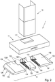
- FIG. 1 an embodiment of the extractor hood 1 according to the invention is shown schematically.
- the extractor hood 1 represents in the embodiment shown a so-called box-Esse dar.
- the hood 1 has a chimney 10 and a below the chimney 10 subsequent viewing hood 11.
- In the chimney 10 is a fan (in FIG. 1 not visible).
- a filter assembly 13 is introduced from below.
- the filter assembly 13 is in the illustrated embodiment of three parts.
- the filter device 130 consists in each case of a filter element 131 and a filter cover 136.
- the filter cover comprises in the illustrated embodiment a filter frame 134 with air guide element 132. Between the top of the filter element 131 and the air guide element 132 of the respective filter device 130, an air guide chamber 133 is formed.
- the side filter devices 130 in this case have such a structure that the filter frame 134 surrounds the flat filter element 131 on three sides. From the edge of the filter element 131, the filter frame 134 extends upwards and merges into the air guide element 132.
- the air guide element 132 is designed in one piece with the filter frame 134. In the illustrated embodiment, the filter frame 134 has a greater height at the rear edge than at the front edge.
- the air guide 132 forms an inclined plane which is inclined from the front edge of the filter element 131 to the rear edge of the filter element 131 upwards.
- a recess 1320 is introduced in the air guide element 132 in the rear region at the edge.
- the entire filter element 131 is covered by the air guide element 132, except for the area below the recess 1320.
- the filter frame 134 is provided at the front edge and the rear edge of the flat filter element 131. Between the front and rear edge of the filter element 131 extends the one with the filter frame 134 ausgestaltetes air guide 132 in the form of a flat, inclined plate arranged.
- the inclination of the air guide element 132 of the central filter device 130 corresponds to the inclination of the air guide elements 132 of the lateral filter devices 130.
- a respective recess 1320 is provided on the two open sides of the filter device 130.
- the size and position of the recesses 1320 corresponds to the size and Position of the recesses 1320 in the right and left filter device 130. Between the recesses 1320, a web 1321 remains.
- the recesses 1320 on the central filter device 130 are separated from the material of the air guiding element 132 by a web 1321.
- two air outlet openings 135 of the filter arrangement 13 are.
- the air outlet openings 135 are aligned with a passage opening 111 in the top of the viewing hood 11.
- the size of the passage opening 111 corresponds to the size of the two air outlet openings 135 and the intermediate web 1321.
- the filter assembly 13 also includes three filter devices 130.
- the width of the three filter devices 130 is the same in this embodiment.
- cover parts 1322 are provided on the side filter devices 130 in the recesses 1320, which cover part of the surface of the recess 1320 formed in the air guide element 132.
- the cover parts 1322 are provided in the recesses 1320 so that the open part of the recess 1320 continues to be on the open side of the filter device 130, that is, the side facing the further filter device 130.
- the central filter device 130 can be recessed. There are thus only the two lateral filter devices 130 introduced into the hood. Since the cover parts 1322 would make the remaining air outlet opening 135 between them too small, in this embodiment of the filter arrangement 13, the cover parts 1322 can be removed from the recesses 1320, in particular broken out. Thus, the entire surfaces of the two recesses 1320 are available as an air outlet opening 135 of the filter arrangement 13 consisting of two filter devices 130.
- the filter element 131 is held in the filter frame 134 of the filter cover 136.
- the filter frame 134 in turn is attached to the air intake opening 110 in the underside of the viewing hood 11.
- one or more fixed pins or hooks may be provided on the rear side of the individual filter devices 130.
- At the front of the filter devices 130 may then be provided corresponding fastening means 137, for example in the form of retractable pins or hooks.
- the filter assembly 13 is not connected to the top of the viewing hood 11.
- the air outlet opening 135 of the filter device abuts against the passage opening 111 of the viewing hood 11.
- the interior of the viewing hood 11 is delimited from the air guide 133 of the filter assembly 13. Via the air outlet opening 135 and the passage opening 111, air can thus pass from the air guide region 133 into the fan housing 120, in which the fan 120 is provided.
- the entire filter arrangement 13 can be removed as a part or at least in each case the individual filter devices 130 of the filter arrangement 13 in each case as a unit from the extractor hood 1 and in particular the viewing hood 11.
- the filter element 131 is taken out of the extractor hood 1 together with the filter cover 136, which comprises the filter frame 134 and the air guide element 132. This is in FIG. 5 indicated schematically.
- the thus removed filter device 130 or filter devices 130 can be cleaned, for example, in a dishwasher.
- FIG. 5 consists of the viewing hood in the embodiment shown exclusively from the outer panel.
- An inner lining of the viewing hood is not required in the extractor hood 1 according to the invention, since the one or more of the air guide elements 132 of the filter assembly 13 take over this function.
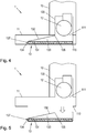
- FIG. 6 is a schematic sectional view of another embodiment of a filter assembly 13 according to the invention shown. Notwithstanding the in FIGS. 4 and 5 shown embodiment is in the embodiment of the filter assembly 13 after FIG. 6 a filter frame 134 is provided, which extends along the side of the filter element 131 and on the underside of the filter element 131 has an inwardly bent edge.
- the filter element 131 which in FIG. 6 is present as a frameless filter element 131 is thus held in the filter frame 134 and can be inserted, for example, in this inseparably connected, for example, injected.
- the further construction of the filter assembly 13 corresponds to that in the FIGS. 4 and 5 shown embodiment.
- the attachment means 137 which is preferably provided in the region of the filter element 131 is not shown. But is also preferred in the embodiment according to FIG. 6 a fastening means 137, for example in the form of retractable locking pins provided.
- FIG. 7 a further embodiment of a filter assembly 13 according to the invention is shown in a schematic sectional view.
- This embodiment corresponds to the in FIG. 6 shown embodiment and differs from this only by the filter element 131 used.
- the filter element 131 is a filter element 131 with element frame 1310.
- the filter element 131 is held over the element frame 1310 in the filter frame 134 and can for example be inserted into this or inextricably linked thereto, for example injected.
- fasteners 137 are preferably provided on this embodiment of the filter assembly 13, in the FIG. 7 but not shown.
- an extractor hood in the form of a so-called box hood, wherein the viewing hood has a box shape can be used.
- This box hood can be configured without a so-called inner frame, that is, in the field of the viewing hood only from the outer wall of the viewing hood - possibly with light bar and controls - exist.
- the filter assembly according to the invention can be introduced or inserted from below.
- the filter material which may also be referred to as filter medium
- a filter cover which may also be referred to as a hood-like apron, preferably inseparably connected to a kind of cartridge.
- This apron is designed under aerodynamic aspects.
- a left and a right filter cartridge together in a 60cm hood that is a hood with a width of the viewing hood of 60 cm, be installed.
- the three different filter cartridges fit together, for example, in a 90cm hood and two middle and the respective side filter cartridges, a 120cm hood can be displayed.
- the use of the filter arrangement according to the invention facilitates the cleaning of, for example, standard / design hoods and has an increased grease filter property.
- no cumbersome cleaning of the hood interior is necessary because it can no longer pollute.
- the filter element can be cleaned in the dishwasher together with the soiled filter cover, which is also referred to as an apron.
- the noise can be reduced because dishwashing machine-resistant insulating material with in the air guide, which can also be referred to as a filter room or filter interior, can be introduced, can be introduced.
Description
Die vorliegende Erfindung betrifft eine Filteranordnung für eine Dunstabzugshaube sowie eine Dunstabzugshaube mit einer solchen Filteranordnung.The present invention relates to a filter assembly for an extractor hood and an extractor hood with such a filter assembly.
Zum Reinigen von Dünsten und Wrasen, die insbesondere beim Kochen entstehen, ist es bekannt, Dunstabzugshauben einzusetzen. Hierin werden in den Dünsten und Wrasen enthaltene Verunreinigungen, wie Fett, Flüssigkeiten oder andere mitgerissene Partikel in sogenannten Fettfiltern abgeschieden. Die Fettfilter stellen in der Regel Filterkassetten dar, die in die Ansaugöffnung der Dunstabzugshaube eingebracht und in dieser Ansaugöffnung befestigt werden. Beispielsweise erfolgt die Befestigung mittels Raststiften am Rand der Filterkassette zum Eingriff in entsprechende Öffnungen an einer Sichthaube der Dunstabzugshaube.For cleaning of fumes and vapors, which arise in particular when cooking, it is known to use cooker hoods. Herein, impurities contained in the fumes and vapors, such as grease, liquids or other entrained particles are deposited in so-called grease filters. The grease filters are usually filter cassettes, which are introduced into the suction opening of the extractor and fixed in this intake. For example, the attachment takes place by means of locking pins on the edge of the filter cartridge for engagement in corresponding openings on a viewing hood of the extractor hood.
Ein Nachteil, der bei dieser Art der Verwendung von Fettfiltern besteht, ist, dass zumindest ein Teil der Verunreinigungen durch den Fettfilter hindurch treten kann und diese dann ins Inneren der Dunstabzugshaube gelangen, wo sie sich an der Innenseite des Gehäuses der Dunstabzugshaube, insbesondere an der Innenseite der Sichthaube der Dunstabzugshaube absetzen. Das Innere der Dunstabzugshaube ist selbst nach Entnahme der Fettfilter für den Benutzer der Dunstabzugshaube schwer zu erreichen und lässt sich daher schwer reinigen.A disadvantage associated with this type of use of grease filters is that at least some of the contaminants can pass through the grease filter and then enter the interior of the extractor hood, where they adhere to the inside of the housing of the extractor hood, in particular at the Lower the inside of the hood of the extractor hood. The interior of the cooker hood is difficult to reach even after removal of the grease filter for the user of the hood and can therefore be difficult to clean.
In der
Ein Nachteil dieser Dunstabzugshaube besteht darin, dass die Handhabung des Innenrahmens und der Filterelemente zur Befestigung an der Dunstabzugshaube aufwendig ist.A disadvantage of this extractor hood is that the handling of the inner frame and the filter elements for attachment to the hood is expensive.
Aufgabe der vorliegenden Erfindung ist es somit eine Lösung zu schaffen, mit der auf einfache Weise und bei einfachem Aufbau der Dunstabzugshaube eine zuverlässige Abscheidung von Fettpartikeln erfolgen kann und mittels derer gleichzeitig das ungewünschte Abscheiden von Partikeln im Inneren der Dunstabzugshaube zuverlässig verhindert werden kann.Object of the present invention is thus to provide a solution that can be done with a simple manner and a simple construction of the hood reliable separation of fat particles and by means of which at the same time the unwanted separation of particles inside the hood can be reliably prevented.
Der Erfindung liegt die Erkenntnis zugrunde, dass diese Aufgabe gelöst werden kann, indem eine Filteranordnung geschaffen wird, die auch einen Teil des Inneren der Dunstabzugshaube abdeckt.The invention is based on the finding that this object can be achieved by providing a filter arrangement which also covers part of the interior of the extractor hood.
Gemäß einem ersten Aspekt der Erfindung wird die Aufgabe gelöst durch eine Filteranordnung für eine Dunstabzugshaube, die mindestens eine Filtervorrichtung mit mindestens einem Filterelement aufweist. Die Filtervorrichtung weist eine Filterabdeckung für das mindestens eine Filterelement auf, die zumindest ein Luftleitelement umfasst, das mit dem Filterelement verbunden ist. Zwischen der Oberseite des mindestens einen Filterelementes und dem Luftleitelement ist ein Luftleitraum gebildet. Die Filtervorrichtung weist Befestigungsmittel zur lösbaren Befestigung der Filtervorrichtung an einer Dunstabzugshaube auf. Zumindest im Bereich des Luftleitelementes dient die Filterabdeckung zur gezielten Luftführung von Luft von der Oberseite des Filterelementes zu einer Luftauslassöffnung der Filteranordnung. Die Filteranordnung ist dadurch gekennzeichnet, dass die Filtervorrichtung eine vormontierte Einheit ist und dass das Filterelement unlösbar mit der Filterabdeckung der Filtervorrichtung verbunden ist.According to a first aspect of the invention, the object is achieved by a filter arrangement for an extractor hood, which has at least one filter device with at least one filter element. The filter device has a filter cover for the at least one filter element, which comprises at least one air guide element, which is connected to the filter element. Between the top of the at least one filter element and the air guide an air guide is formed. The filter device has fastening means for releasably securing the filter device to an extractor hood. At least in the region of the air guiding element, the filter cover serves for targeted air guidance of air from the upper side of the filter element to an air outlet opening of the filter arrangement. The filter assembly is characterized in that the filter device is a preassembled unit and that the filter element is permanently connected to the filter cover of the filter device.
Als Filteranordnung wird eine Baugruppe bezeichnet, die zum Abscheiden von Partikeln, insbesondere von Fett aus Dünsten und Wrasen in einer Dunstabzugshaube dient. Die erfindungsgemäße Dunstabzugshaube stellt beispielsweise eine so genannte Esse dar, bei der ein Lüftergehäuse in einem Kamin aufgenommen ist. An den Kamin schließt sich nach unten eine Sichthaube an, die den Kamin zumindest teilweise umgibt und/oder über diesen nach vorne und/oder zu den Seiten hinausragt. Die erfindungsgemäße Filteranordnung kann aber auch in anderen Arten von Dunstabzugshauben eingesetzt werden, beispielsweise in Unterbauhauben. Die Filteranordnung besteht aus mindestens einer Filtervorrichtung. Jede Filtervorrichtung stellt hierbei eine vormontierbare Einheit dar. Dies bedeutet, dass die Filtervorrichtung als eine Einheit in die Dunstabzugshaube eingesetzt und aus dieser entnommen werden kann. Als Filtervorrichtung wird hierbei eine Baugruppe bezeichnet, die mindestens ein Filterelement umfasst. In der einfachsten Ausführungsform besteht die Filteranordnung aus einer einzigen Filtervorrichtung. Vorzugsweise sind aber mindestens zwei oder mehr Filtervorrichtungen in einer Filteranordnung enthalten.As a filter assembly, an assembly is referred to, which serves for the separation of particles, in particular fat from fumes and vapor in an extractor hood. The extractor hood according to the invention represents, for example, a so-called Esse, in which a fan housing is accommodated in a chimney. The fireplace is followed by a viewing hood down, which at least partially surrounds the chimney and / or protrudes over this forward and / or to the sides. The filter assembly according to the invention can also be used in other types of cooker hoods be, for example, in substructure hoods. The filter assembly consists of at least one filter device. Each filter device in this case represents a preassembled unit. This means that the filter device can be used as a unit in the extractor hood and removed therefrom. As a filter device in this case an assembly is referred to, which comprises at least one filter element. In the simplest embodiment, the filter assembly consists of a single filter device. Preferably, however, at least two or more filter devices are contained in a filter assembly.
Als Filterelement wird ein Element der Filtervorrichtung bezeichnet, das zumindest bereichsweise aus einem Filtermaterial besteht. Das Filterelement kann beispielsweise aus Streckmetallfilterlagen bestehen, die gegebenenfalls in einem Elementrahmen gehalten sind.As a filter element, an element of the filter device is referred to, which consists at least partially of a filter material. The filter element may for example consist of expanded metal filter layers, which are optionally held in an element frame.
Erfindungsgemäß weist die Filtervorrichtung zusätzlich zu dem Filterelement eine Filterabdeckung auf. Die Filterabdeckung kann auch als Schürze bezeichnet werden. Die Filterabdeckung umfasst ein Luftleitelement. Das Luftleitelement ist mit dem Filterelement verbunden. Insbesondere ist das Luftleitelement an dem Filterelement mittelbar oder unmittelbar befestigt. Das Luftleitelement ist aus einem luftundurchlässigen Material hergestellt. Zumindest im Bereich des Luftleitelementes dient die Filterabdeckung daher zur Luftführung in der Filteranordnung und insbesondere zur gezielten Luftführung von Luft von der Oberseite des Filterelementes zu einer Luftauslassöffnung der Filteranordnung. Die Filterabdeckung kann aus Kunststoff oder Metall hergestellt sein. Insbesondere kann es sich bei der Filterabdeckung um ein Spritzgussteil oder ein Biegeteil handeln.According to the invention, the filter device has a filter cover in addition to the filter element. The filter cover can also be called an apron. The filter cover comprises an air guide element. The air guide element is connected to the filter element. In particular, the air guide element is attached directly or indirectly to the filter element. The air guide is made of an air-impermeable material. At least in the region of the air guide element, the filter cover therefore serves for air guidance in the filter arrangement and in particular for targeted air guidance of air from the upper side of the filter element to an air outlet opening of the filter arrangement. The filter cover may be made of plastic or metal. In particular, the filter cover may be an injection-molded part or a bent part.
Das Luftleitelement ist erfindungsgemäß so vorgesehen, dass zwischen der Oberseite des Filterelementes und dem Luftleitelement ein Luftleitraum gebildet wird. Zu diesem Zweck ist das Luftleitelement zumindest bereichsweise von der Oberseite des Filterelementes beabstandet. Der Luftleitraum wird somit nach unten von der Oberseite des Filterelementes begrenzt. Nach oben und zu den Seiten wird der Luftleitraum durch das Luftleitelement zumindest bereichsweise begrenzt, wie später genauer erläutert wird. Besonders bevorzugt weist der Luftleitraum der Filteranordnung, der gegebenenfalls durch mehrere Luftleiträume von Filtervorrichtungen gebildet wird, somit lediglich einen Lufteinlass über das Filterelement und einen nach vorzugsweise nach oben gerichteten Luftauslass auf. Die Wände des Luftleitraumes, die durch das oder die Luftleitelemente gebildet werden, sind hingegen luftundurchlässig.The spoiler is inventively provided so that between the top of the filter element and the spoiler an air guide is formed. For this purpose, the air guide element is at least partially spaced from the top of the filter element. The air guide is thus limited downwards from the top of the filter element. Upwards and to the sides of the air guide is at least partially limited by the air guide element, as will be explained in more detail later. Particularly preferably, the Luftleitraum the filter assembly, which is optionally formed by a plurality Luftleiträume of filter devices, thus only one Air inlet via the filter element and a preferably upwardly directed air outlet. The walls of the air duct, which are formed by the one or more air guide elements, however, are impermeable to air.
Richtungsangaben betreffend die Filteranordnung oder Teile der Filteranordnung, wie oben oder unten, beziehen sich soweit nicht anderes angegeben auf die Filteranordnung in dem in einer Dunstabzugshaube eingebrachten Zustand der Filteranordnung. Insbesondere beziehen sich diese Richtungsangaben auf eine Filteranordnung, die in eine horizontal liegende Ansaugöffnung der Dunstabzugshaube eingebracht ist.Direction information regarding the filter assembly or parts of the filter assembly, such as above or below, unless otherwise stated, refer to the filter assembly in the state of the filter assembly inserted in an extractor hood. In particular, these directions relate to a filter arrangement which is introduced into a horizontal suction opening of the extractor hood.
Die erfindungsgemäße Filteranordnung weist weiterhin Befestigungsmittel zur lösbaren Befestigung der Filtervorrichtung an einer Dunstabzugshaube auf. Als Befestigungsmittel können beispielsweise Rastvorrichtungen, Stifte oder Haken eingesetzt werden. Alternativ können als Befestigungsmittel auch Aufnahmeöffnungen für Rastvorrichtungen, Stifte oder Haken verwendet werden. Weiterhin können die Befestigungsmittel beispielsweise auch Magneten sein.The filter assembly according to the invention further comprises fastening means for releasably securing the filter device to an extractor hood. As fastening means, for example latching devices, pins or hooks can be used. Alternatively, as a fastening means also receiving openings for locking devices, pins or hooks can be used. Furthermore, the fastening means may for example also be magnets.
Indem bei der erfindungsgemäßen Filteranordnung eine Filterabdeckung vorgesehen ist, die ein Luftleitelement umfasst, das so ausgelegt und angeordnet ist, dass zwischen der Oberseite des Filterelementes und dem Luftleitelement ein Luftleitraum gebildet ist, können Verunreinigungen, die das Filterelement der Filtervorrichtung passieren sollten, an dem Luftleitelement und somit an einem Teil der Filteranordnung abgeschieden werden. Eine Verunreinigung des Gehäuses der Dunstabzugshaube, insbesondere der Innenseite der Sichthaube kann somit verhindert werden. Da zudem an der Filteranordnung Befestigungsmittel zur lösbaren Befestigung der Filtervorrichtung an der Dunstabzugshaube vorgesehen sind, ist es möglich die Filtervorrichtung aus der Dunstabzugshaube zu entnehmen, um diese beispielsweise zu reinigen. Indem die Filtervorrichtung eine vormontierbare Einheit darstellt, kann, außer dem Filterelement auch die damit verbundene Filterabdeckung gleichzeitig aus der Dunstabzugshaube entnommen und kann somit ebenfalls außerhalb der Dunstabzugshaube gereinigt werden. Da die Filterabdeckung mit dem Filterelement verbunden ist, kann die Filtervorrichtung als Einheit aus der Dunstabzugshaube entnommen und in diese eingesetzt werden, wodurch die Handhabung und Reinigung der Filteranordnung weiter vereinfacht wird.By providing a filter cover in the filter arrangement according to the invention which comprises an air guide element which is designed and arranged such that an air guide space is formed between the upper side of the filter element and the air guide element, impurities that should pass through the filter element of the filter device can be provided on the air guide element and thus deposited on a portion of the filter assembly. Contamination of the housing of the hood, in particular the inside of the viewing hood can thus be prevented. In addition, since fastening means for releasably securing the filter device to the extractor hood are provided on the filter arrangement, it is possible to remove the filter device from the extractor hood in order to clean it, for example. By the filter device is a pre-assembled unit, except the filter element and the associated filter cover removed simultaneously from the hood and can thus also be cleaned outside the hood. Since the filter cover is connected to the filter element, the filter device can be removed as a unit from the hood and inserted into it, whereby the handling and cleaning of the filter assembly is further simplified.
Die Filtervorrichtung stellt eine vormontierte Einheit dar. Dies bedeutet, dass das Filterelement und die Filterabdeckung vor dem Einbringen in die Dunstabzugshaube miteinander verbunden werden können.The filter device is a preassembled unit. This means that the filter element and the filter cover can be connected to each other before introduction into the hood.
Gemäß einer weiteren Ausführungsform stellt die Filtervorrichtung, das heißt das Filterelement mit der dazugehörigen Filterabdeckung der Filtervorrichtung, eine vormontierte Einheit dar. Erfindungsgemäß ist das Filterelement unlösbar mit der Filterabdeckung der Filtervorrichtung verbunden. Beispielsweise kann die Filterabdeckung an das Filterelement angeformt sein, beispielsweise durch Biegen oder Anspritzen. Insbesondere bei dieser Ausführungsform kann das Filterelement auch ein rahmenloses Filterelement sein, das lediglich aus dem Filtermaterial, beispielsweise aus Filterlagen besteht aber keinen Elementrahmen aufweist. Indem die Filtervorrichtung eine vormontierte Einheit darstellt, ist deren Handhabung weiter vereinfacht. Insbesondere kann die Filtervorrichtung zuverlässig als eine Einheit aus der Dunstabzugshaube entnommen, gereinigt und wieder in die Dunstabzugshaube eingesetzt werden.According to a further embodiment, the filter device, that is to say the filter element with the associated filter cover of the filter device, constitutes a preassembled unit. According to the invention, the filter element is permanently connected to the filter cover of the filter device. For example, the filter cover may be formed on the filter element, for example by bending or molding. In particular, in this embodiment, the filter element may also be a frameless filter element, which consists only of the filter material, for example, filter layers but has no element frame. By the filter device is a preassembled unit, their handling is further simplified. In particular, the filter device can be reliably removed as a unit from the cooker hood, cleaned and used again in the hood.
Gemäß einer bevorzugten Ausführungsform sind die Befestigungsmittel zur lösbaren Befestigung der Filtervorrichtung an der Dunstabzugshaube an der Filtervorrichtung im Bereich des Filterelementes der Filtervorrichtung vorgesehen. Im Bereich des Filterelementes bedeutet in diesem Zusammenhang vorzugsweise im Bereich der Ebene des Filterelementes. Den Vorteil, den diese Anordnung des oder der Befestigungsmittel aufweist besteht darin, dass diese für den Benutzer der Dunstabzugshaube einfach zugänglich sind und auch bei eingebrachtem Filterelement die Filtervorrichtung von der Dunstabzugshaube gelöst werden kann. Beispielsweise kann in der Unterseite des Filterelementes ein Griff zum Betätigen von einfahrbaren Raststiften vorgesehen sein, die über das Filterelement und einen gegebenenfalls vorgesehenen Filterrahmen der Filterabdeckung hinausragen. Durch Einbringen dieser Raststifte in entsprechende Öffnungen in der Ansaugöffnung der Dunstabzugshaube, insbesondere der Sichthaube, wird somit die gesamte Filteranordnung einschließlich der Filterabdeckung in der Dunstabzugshaube gehalten. Ein separates Befestigen der Filterabdeckung beim Einbringen und Lösen der Filterabdeckung zum Herausnehmen ist hierbei nicht erforderlich.According to a preferred embodiment, the fastening means for releasably securing the filter device to the extractor hood on the filter device are provided in the region of the filter element of the filter device. In the area of the filter element means in this context preferably in the region of the plane of the filter element. The advantage of having this arrangement of the fastener or is that they are easily accessible to the user of the hood and even with a fitted filter element, the filter device can be solved by the cooker hood. For example, a handle for actuating retractable locking pins may be provided in the underside of the filter element, which protrude beyond the filter element and an optionally provided filter frame of the filter cover. By introducing these locking pins into corresponding openings in the suction opening of the extractor hood, in particular the viewing hood, the entire filter arrangement including the filter cover is thus held in the extractor hood. A separate attachment of the filter cover when inserting and loosening the filter cover to remove this is not required.
Vorzugsweise erstreckt sich das Luftleitelement von zumindest einem Teil des Randes des Filterelementes aus nach oben. Die Erstreckungsrichtung des Luftleitelementes kann hierbei über die Länge des Luftleitelementes variieren. So kann das Luftleitelement von dem Rand des Filterelementes geneigt nach oben ausgerichtet sein und im weiteren Verlauf des Luftleitelementes in eine zu der Oberfläche des Filterelementes nach oben geneigte Fläche übergehen. Zudem kann das Luftleitelement auch Bereiche aufweisen, die zu der Oberfläche des Filterelementes parallel verlaufen. Vorzugsweise ist das Luftleitelement zumindest bereichsweise zu der Oberfläche des Filterelementes geneigt ausgerichtet ist. Durch eine solche Neigung kann eine Verbesserung der Strömungsbedingungen in dem Luftleitraum der Filtervorrichtung erzielt werden. Zudem kann bei einer zumindest bereichsweise vorgesehenen Neigung des Luftleitelementes ein Abscheiden von Verunreinigungen, die durch das Filterelement passiert sind, verbessert werden und ein Heruntertropfen im Vergleich zu einer parallel zu der Oberfläche des Filterelementes ausgerichteten Fläche verhindern. Somit wird die Fettabscheiderate der Filteranordnung verbessert, da auch der Teil der Verunreinigungen, die sich an der Filterabdeckung absetzen zu der Fettabscheiderate gerechnet werden, da auch die Filterabdeckung aus der Dunstabzugshaube entnommen und gereinigt werden kann.Preferably, the air guiding element extends from at least a part of the edge of the filter element upwards. The extension direction of the air guide element can vary over the length of the air guide element. Thus, the air-guiding element can be inclined upwards from the edge of the filter element and, in the further course of the air-guiding element, pass into an area inclined upwards to the surface of the filter element. In addition, the air guide element can also have regions which run parallel to the surface of the filter element. Preferably, the air guide is at least partially aligned with the surface of the filter element is inclined. By such a tendency, an improvement in the flow conditions in the Luftleitraum the filter device can be achieved. In addition, in the case of an at least partially provided inclination of the air guiding element, a separation of impurities which have passed through the filter element can be improved and prevent dripping down in comparison with a surface aligned parallel to the surface of the filter element. Thus, the Fettabscheiderate the filter assembly is improved, as well as the part of the impurities that settle on the filter cover are calculated to the Fettabscheiderate, as well as the filter cover can be removed from the hood and cleaned.
Gemäß einer bevorzugten Ausführungsform deckt das Luftleitelement in senkrechter Projektion auf das Filterelement einen Teil der Fläche des Filterelementes ab und in dem Luftleitelement ist mindestens eine Aussparung vorgesehen, die zumindest einen Teil einer Luftauslassöffnung der Filteranordnung bildet. Das Luftleitelement erstreckt sich hierbei vorzugsweise vom Rand des Filterelementes bis zu einer Position, die der Lufteinlassöffnung für den Lufteinlass in ein dem Filterelement nachgeschalteten Lüftergehäuse entspricht.According to a preferred embodiment, the air guide element covers a part of the surface of the filter element in perpendicular projection onto the filter element and at least one recess is provided in the air guide element which forms at least part of an air outlet opening of the filter arrangement. The air guide element in this case preferably extends from the edge of the filter element to a position which corresponds to the air inlet opening for the air inlet into a fan housing connected downstream of the filter element.
Durch diese Ausgestaltung des Luftleitelementes wird eine zuverlässige Führung der Luft in dem Luftleitraum zu einer Luftauslassöffnung der Filteranordnung gewährleistet und gleichzeitig wird durch die Abdeckung eines Teils der Fläche des Filterelementes ein ungehindertes Durchströmen von Verunreinigungen durch die Filteranordnung verhindert oder zumindest minimiert. Die Fläche der Luftauslassöffnung oder Luftauslassöffnungen der Filteranordnung weist vorzugsweise eine Größe auf, die der Größe einer Lufteinlassöffnung zu dem Gehäuse eines Lüfters der Dunstabzugshaube entspricht. Die Größe der Fläche der Luftauslassöffnung ist, sofern nur eine Luftauslassöffnung an der Filteranordnung vorgesehen ist vorzugsweise gleich der Größe der Fläche der Lufteinlassöffnung. Sind mehrere Luftauslassöffnungen an der Filteranordnung gebildet, so ist die Größe der durch die einzelnen Luftauslassöffnungen gebildeten Fläche lediglich durch Stabilisierungsmittel verringert. Beispielsweise kann als Stabilisierungsmittel ein Steg zwischen zwei Luftaustrittsöffnungen vorgesehen sein. Vorzugsweise besteht die erfindungsgemäße Filteranordnung aus mindestens zwei Filtervorrichtungen. Die Aussparungen an den Luftleitelementen der einzelnen Filtervorrichtungen sind dabei so angeordnet, dass diese im eingebauten Zustand der Filteranordnung in der Dunstabzugshaube aneinander angrenzen. Die durch die Aussparungen definierten Teilflächen bilden dann zusammen eine Luftauslassöffnung. Die Aussparung an dem Luftleitelement ist in dem Bereich des Luftleitelementes vorgesehen, der den größten Abstand zu der Oberfläche des Filterelementes aufweist.This embodiment of the air guide element ensures reliable guidance of the air in the air guide to an air outlet opening of the filter arrangement and at the same time prevents or at least minimizes the flow through the cover by covering part of the surface of the filter element. The area of the air outlet opening or air outlet openings of the filter arrangement preferably has a size which corresponds to the size of an air inlet opening to the housing of a fan of the extractor hood. The size of the surface of the air outlet opening is, if only one air outlet opening on the Filter arrangement is preferably equal to the size of the surface of the air inlet opening. If a plurality of air outlet openings are formed on the filter arrangement, then the size of the area formed by the individual air outlet openings is only reduced by stabilizing means. For example, may be provided as a stabilizing means a web between two air outlet openings. Preferably, the filter arrangement according to the invention consists of at least two filter devices. The recesses on the air guide elements of the individual filter devices are arranged so that they adjoin one another in the installed state of the filter assembly in the hood. The defined by the recesses faces then together form an air outlet. The recess on the air guide element is provided in the region of the air guide element, which has the greatest distance to the surface of the filter element.
Das Filterelement weist vorzugsweise eine rechteckige Form auf. Das Luftleitelement erstreckt sich vorzugsweise von zumindest einem Rand, besonders bevorzugt aber zumindest von mindestens zwei Rändern des Filterelementes aus. Ist das Luftleitelement lediglich an zwei Rändern mit dem Filterelement verbunden, so liegen diese Ränder an gegenüberliegenden Seiten des Filterelementes, insbesondere an der Rückseite und der Vorderseite des Filterelementes. Eine Filtervorrichtung, bei der sich das Luftleitelement lediglich von zwei Rändern aus erstreckt, weist somit zwei offene Seiten auf. An diese offenen Seiten können in der Dunstabzugshaube weitere Filtervorrichtungen angeordnet werden. Bei einer Filtervorrichtung, bei der sich das Luftleitelement von drei Rändern des Filterelementes aus erstreckt, weist die Filtervorrichtung lediglich eine offene Seite auf, an die sich in der Dunstabzugshaube eine weitere Filtervorrichtung anschließen kann. Durch diese Ausgestaltungen der Luftleitelemente können in Dunstabzugshauben größerer Breite mehrere Filtervorrichtungen in der Filteranordnung benachbart zueinander vorgesehen werden. Dies hat den Vorteil, dass die Größe der einzelnen Filtervorrichtungen geringer ist und diese daher für den Benutzer der Dunstabzugshaube einfacher zu handhaben sind.The filter element preferably has a rectangular shape. The air guide element preferably extends from at least one edge, but particularly preferably at least from at least two edges of the filter element. If the air guide element is connected to the filter element only at two edges, then these edges lie on opposite sides of the filter element, in particular on the rear side and the front side of the filter element. A filter device, in which the air guiding element extends only from two edges, thus has two open sides. On these open sides more filter devices can be arranged in the hood. In a filter device in which the air guide element extends from three edges of the filter element, the filter device has only one open side, to which a further filter device can connect in the extractor hood. By means of these embodiments of the air guiding elements, a plurality of filter devices in the filter arrangement can be provided adjacent to one another in exhaust hoods of greater width. This has the advantage that the size of the individual filter devices is smaller and therefore easier for the user of the extractor hood to handle.
Gemäß einer Ausführungsform umfasst die Filterabdeckung einen Filterrahmen und das Luftleitelement ist mit dem Filterrahmen einteilig ausgestaltet. Als Filterrahmen wird hierbei ein Bereich der Filterabdeckung bezeichnet, in dem das Filtermaterial mittelbar oder unmittelbar gehalten wird. Der Filterrahmen bildet somit den unteren Bereich der Filterabdeckung. Wird ein Filterelement mit Elementrahmen, beispielsweise eine Filterkassette verwendet, kann der Filterrahmen der Filterabdeckung eine Führung für den Elementrahmen darstellen. Beispielsweise kann der untere Rand der Filterabdeckung abgekantet sein und so eine Halterung und Führung für den Elementrahmen bilden. Auch bei Verwendung eines rahmenlosen Filterelementes kann der Filterrahmen durch eine Abkantung gebildet sein und dient dann der Aufnahme der Ränder des Filtermaterials, das beispielsweise in die Filterabdeckung von der offenen Seite der Filtervorrichtung eingeschoben werden kann. Alternativ kann der Filterrahmen aber auch mit dem Filtermaterial unlösbar verbunden sein. In diesem Fall kann beispielsweise das Filtermaterial an mindestens einem der Ränder des Filtermaterials mit dem Material der Filterabdeckung verklebt, verschweißt oder auf andere Art verbunden werden, beispielsweise eingespritzt werden. Schließlich ist es auch möglich einen Elementrahmen als Filterrahmen im Sinne der vorliegenden Erfindung zu verwenden. Hierbei wir an den Außenseiten des Elementrahmens des Filterelementes oder an der Oberseite des Elementrahmens das Luftleitelement an dem Elementrahmen befestigt. Diese Befestigung kann beispielsweise mittels Anschweißen, Anspritzen oder dergleichen erfolgen. Gemäß einer weiteren Ausführungsform ist in mindestens einer Filtervorrichtung zumindest bereichsweise ein Dämmmaterial vorgesehen. Das Dämmmaterial ist vorzugsweise in dem Luftleitraum vorgesehen. Beispielsweise kann das Dämmmaterial an der dem Luftleitraum zugewandten Seite des Luftleitelementes vorgesehen und dort befestigt sein. Das Dämmmaterial ist vorzugsweise ein Geräuschdämmmaterial. Zudem ist das Dämmmaterial vorzugsweise geschirrspülmaschienenfest. Durch das Vorsehen eines Geräuschdämmmaterials kann der Geräuschpegel der Dunstabzugshaube insgesamt verringert werden. Zudem wird die Fettabscheiderate bei dieser Ausführungsform weiter gesteigert, da die Oberfläche eines Dämmmaterials in der Regel besser zur Abscheidung von Partikeln geeignet ist, als eine ebene Oberfläche. Da die erfindungsgemäße Filtervorrichtung vormontiert ist, kann das Dämmmaterial in einer Einheit zusammen mit dem Filterelement und der Fitlerabdeckung entnommen werden. Die Handhabung der Filtervorrichtung(en) und damit der Filteranordnung wird daher weiter erleichtert.According to one embodiment, the filter cover comprises a filter frame and the air guide element is designed in one piece with the filter frame. As a filter frame in this case a region of the filter cover is referred to, in which the filter material is held directly or indirectly. The filter frame thus forms the lower part of the Filter cover. If a filter element with an element frame, for example a filter cassette is used, the filter frame of the filter cover can be a guide for the element frame. For example, the lower edge of the filter cover can be folded and thus form a holder and guide for the element frame. Even when using a frameless filter element of the filter frame may be formed by a fold and then serves to receive the edges of the filter material, which can be inserted, for example, in the filter cover of the open side of the filter device. Alternatively, however, the filter frame can also be permanently connected to the filter material. In this case, for example, the filter material can be glued, welded or otherwise connected to at least one of the edges of the filter material with the material of the filter cover, for example, be injected. Finally, it is also possible to use an element frame as a filter frame in the sense of the present invention. In this case, we attached to the outer sides of the element frame of the filter element or on the upper side of the element frame, the air guide element on the element frame. This attachment can be done for example by means of welding, spraying or the like. According to a further embodiment, an insulating material is at least partially provided in at least one filter device. The insulating material is preferably provided in the air guide. For example, the insulating material may be provided on the side of the air guide element facing the air guide space and fastened there. The insulating material is preferably a Geräuschdämmmaterial. In addition, the insulating material is preferably dishwasher-safe. By providing a noise insulating material, the noise level of the extractor hood can be reduced overall. In addition, the fat removal rate is further increased in this embodiment, since the surface of an insulating material is generally better suited for the deposition of particles, as a flat surface. Since the filter device according to the invention is pre-assembled, the insulating material can be removed in one unit together with the filter element and the Fitlerabdeckung. The handling of the filter device (s) and thus the filter assembly is therefore further facilitated.
Gemäß einer weiteren Ausführungsform ist zumindest ein Teil der Aussparung des Luftleitelementes durch ein Deckteil abgedeckt. Das Deckteil ist vorzugsweise mit dem Luftleitelement über eine Sollbruchstelle verbunden. Dadurch kann das Deckteil durch Herausbrechen von dem Luftleitelement und damit aus dem Bereich der Aussparung entfernt werden. Den Vorteil, den ein Vorsehen eines solchen Deckteils aufweist, besteht darin, dass die Größe der Luftauslassöffnung den Gegebenheiten in der Dunstabzugshaube auf einfache Weise angepasst werden kann. So kann bei einer Dunstabzugshaube, bei der drei Filtervorrichtungen benachbart zueinander vorgesehen werden müssen, die Größe der Luftauslassöffnung durch die Deckteile auf die Größe der Lufteinlassöffnung des Lüftergehäuses verringert sein. Sind hingegen in der Dunstabzugshaube nur zwei Filtervorrichtungen einzubringen, können die Deckteile der Filtervorrichtungen entfernt werden und so die Größe der Luftauslassöffnung auf die Größe der Lufteinlassöffnung vergrößert werden.According to a further embodiment, at least part of the recess of the air guiding element is covered by a cover part. The cover part is preferably with the Air guide connected via a predetermined breaking point. As a result, the cover part can be removed by breaking away from the air guide element and thus out of the region of the recess. The advantage of providing such a cover part is that the size of the air outlet opening can be easily adapted to the conditions in the extractor hood. Thus, in the case of an extractor hood, in which three filter devices must be provided adjacent to one another, the size of the air outlet opening through the cover parts can be reduced to the size of the air inlet opening of the fan housing. On the other hand, if only two filter devices are to be introduced in the extractor hood, the cover parts of the filter devices can be removed, thus increasing the size of the air outlet opening to the size of the air inlet opening.
Durch das Vorsehen von Deckteilen kann daher bei minimierter Lagerhaltung und vereinfachter Herstellung auf einfache Weise die zuverlässige Führung von Luft von dem Filterelement zu der Luftauslassöffnung der Filteranordnung und über diese zu der Lufteinlassöffnung des Lüftergehäuses gewährleistet werden. Zudem wird ein unerwünschtes Durchtreten von Verunreinigungen durch die Luftaustrittsöffnung der Filteranordnung in einen Bereich der Dunstabzugshaube außer dem Gehäuse des Lüfters der Dunstabzugshaube verhindert.By providing cover parts can therefore be ensured with minimized storage and simplified production in a simple manner the reliable management of air from the filter element to the air outlet of the filter assembly and through this to the air inlet opening of the fan housing. In addition, an undesirable passage of contaminants through the air outlet opening of the filter assembly is prevented in a region of the extractor hood except the housing of the fan of the hood.
Gemäß einem weiteren Aspekt betrifft die Erfindung eine Dunstabzugshaube. Vorteile und Merkmale, die bezüglich der Filteranordnung beschrieben wurden, gelten - soweit anwendbar - entsprechend für die Dunstabzugshaube und umgekehrt.According to a further aspect, the invention relates to an extractor hood. Advantages and features that have been described with respect to the filter assembly, apply - where applicable - according to the cooker hood and vice versa.
Die erfindungsgemäße Dunstabzugshaube zeichnet sich dadurch aus, dass diese eine erfindungsgemäße Filteranordnung aufweist.The extractor hood according to the invention is characterized in that it has a filter arrangement according to the invention.
Gemäß einer bevorzugten Ausführungsform ist in der Dunstabzugshaube eine Filteranordnung mit mindestens zwei Filtervorrichtungen angeordnet, wobei die Filtervorrichtungen zueinander benachbart vorliegen und die Luftleiträume der mindestens zwei Filtervorrichtungen ineinander übergehen. Bei dieser Ausführungsform sind die Filtervorrichtungen daher so in der Filteranordnung und damit in der Dunstabzugshaube angeordnet, dass offene Seiten der Filtervorrichtungen einander zugewandt sind. Gemäß einer Ausführungsform sind zwei seitliche Filtervorrichtungen vorgesehen, die so nebeneinander angeordnet sind, dass deren Liftleiträume zueinander offen sind. Dadurch wird durch die beiden Luftleiträume der Luftleitraum der Filteranordnung gebildet. Vorzugsweise weisen die beiden seitlichen Filtervorrichtungen spiegelsymmetrische Forme auf.According to a preferred embodiment, a filter arrangement with at least two filter devices is arranged in the extractor hood, wherein the filter apparatuses are adjacent to one another and the air ducts of the at least two filter apparatuses merge into one another. In this embodiment, the filter devices are therefore arranged in the filter assembly and thus in the hood so that open sides of the filter devices face each other. According to one embodiment, two lateral filter devices are provided, which are arranged side by side so that their Liftleiträume are open to each other. As a result, the air guide space of the filter arrangement is formed by the two air guide spaces. Preferably, the two lateral filter devices have mirror-symmetrical shapes.
Gemäß einer weiteren Ausführungsform sind zwei seitliche Filtervorrichtungen und eine mittlere Filtervorrichtung vorgesehen und die seitlichen Filtervorrichtungen unterscheiden sich zumindest in ihrer Form von der mittleren Filtervorrichtung. Bei dieser Ausführungsform weisen die seitlichen Filtervorrichtungen vorzugsweise Luftleitelemente auf, die sich jeweils von drei Rändern des Filterelementes aus erstrecken. Die mittlere Filtervorrichtung hingegen weist hierbei ein Luftleitelement auf, das sich von einem oder zwei gegenüberliegenden Rändern aus erstreckt. Somit besitzen die seitlichen Filtervorrichtungen jeweils eine offene Seite und die mittlere Filtervorrichtung zwei gegenüberliegende offene Seiten. An die beiden gegenüberliegenden offenen Seiten der mittleren Filtervorrichtung wird jeweils eine der seitlichen Filtervorrichtungen mit deren offenen Seite angefügt.According to a further embodiment, two lateral filter devices and one middle filter device are provided and the lateral filter devices differ at least in their shape from the middle filter device. In this embodiment, the lateral filter devices preferably have air guide elements which each extend from three edges of the filter element. The middle filter device, however, in this case has an air guide element which extends from one or two opposite edges. Thus, the side filter devices each have an open side and the middle filter device two opposing open sides. To each of the two opposite open sides of the middle filter device one of the lateral filter devices is attached with its open side.
Ist mehr als eine Filtervorrichtung in der Filteranordnung vorhanden, so sind diese vorzugsweise nicht unmittelbar miteinander verbunden, liegen aber besonders bevorzugt aneinander an. Die relative Position der einzelnen Filtervorrichtungen zueinander wird über die Befestigung der Filtervorrichtungen an der Dunstabzugshaube eingestellt.If more than one filter device is present in the filter arrangement, these are preferably not connected directly to one another, but are particularly preferably adjacent to one another. The relative position of the individual filter devices to one another is set via the attachment of the filter devices to the extractor hood.
Gemäß einer bevorzugten Ausführungsform wird die mindestens eine Luftauslassöffnung der Filteranordnung durch Aussparungen von mindestens zwei Luftleitelementen gebildet. Alternativ ist es auch möglich die Luftauslassöffnung nur in einer von mehreren Filtervorrichtungen vorzusehen.According to a preferred embodiment, the at least one air outlet opening of the filter arrangement is formed by recesses of at least two air guide elements. Alternatively, it is also possible to provide the air outlet opening only in one of a plurality of filter devices.
Gemäß einer weiteren Ausführungsform weist die Dunstabzugshaube eine Sichthaube auf, deren Korpus ausschließlich aus dem Außenmaterial der Sichthaube gebildet ist und die Filteranordnung lösbar in der Sichthaube befestigt ist. Bei einer Dunstabzugshaube, die eine Sichthaube aufweist, handelt es sich insbesondere um eine Esse, die oberhalb der Sichthaube einen Kamin aufweist. Indem bei der erfindungsgemäßen Dunstabzugshaube eine Filteranordnung verwendet wird, die eine Filterabdeckung aufweist, kann die Ausgestaltung der Sichthaube, in die die Filteranordnung eingebracht wird, vereinfacht werden. Insbesondere ist es nicht erforderlich einen Innenrahmen oder ein anderes Luftleitelement als Teil der Sichthaube vorzusehen. Bei der vorliegenden Erfindung bei der die Filteranordnung eine Filterabdeckung mit Luftleitelement aufweist, kann zudem durch dieses Luftleitelement die Luftführung von dem Filterelement zu dem Gebläse der Dunstabzugshaube gewährleistet werden.According to a further embodiment, the extractor hood has a viewing hood whose body is formed exclusively from the outer material of the viewing hood and the filter assembly is detachably mounted in the viewing hood. In an extractor hood, which has a viewing hood, it is in particular a dining, which has a chimney above the viewing hood. By using in the extractor hood according to the invention a filter assembly comprising a filter cover has, the design of the viewing hood, in which the filter assembly is introduced, can be simplified. In particular, it is not necessary to provide an inner frame or another air guide element as part of the viewing hood. In the present invention, in which the filter assembly comprises a filter cover with air guide, can also be ensured by this air guide the air flow from the filter element to the fan of the hood.
Die Erfindung wird im Folgenden erneut unter Bezugnahme auf die beiliegenden Zeichnungen genauer beschrieben. Es zeigen:
-
Figur 1 : eine perspektivische Ansicht einer Ausführungsform einer erfindungsgemäßen Dunstabzugshaube; -
Figur 2 : eine perspektivische Explosionsansicht der Ausführungsform der Dunstabzugshaube nachFigur 1 ; -
Figur 3 : eine perspektivische Explosionsansicht einer weiteren Ausführungsform einer erfindungsgemäßen Dunstabzugshaube; -
Figur 4 : eine schematische Schnittansicht einer Ausführungsform einer erfindungsgemäßen Dunstabzugshaube mit eingebrachter Filteranordnung; -
Figur 5 : eine schematische Schnittansicht der Ausführungsform der erfindungsgemäßen Dunstabzugshaube nachFigur 4 mit entnommener Filteranordnung; -
Figur 6 : eine schematische Schnittansicht einer weiteren Ausführungsform einer erfindungsgemäßen Filteranordnung; und -
Figur 7 : eine schematische Schnittansicht einer weiteren Ausführungsform einer erfindungsgemäßen Filteranordnung.
-
FIG. 1 a perspective view of an embodiment of an extractor hood according to the invention; -
FIG. 2 : An exploded perspective view of the embodiment of the hood afterFIG. 1 ; -
FIG. 3 a perspective exploded view of another embodiment of an extractor hood according to the invention; -
FIG. 4 a schematic sectional view of an embodiment of an extractor hood according to the invention with incorporated filter assembly; -
FIG. 5 : A schematic sectional view of the embodiment of the extractor hood according to the inventionFIG. 4 with removed filter assembly; -
FIG. 6 a schematic sectional view of a further embodiment of a filter arrangement according to the invention; and -
FIG. 7 : A schematic sectional view of another embodiment of a filter arrangement according to the invention.
In
Wie sich aus
Bei der mittleren Filtervorrichtung 130 ist der Filterrahmen 134 an dem vorderen Rand und dem hinteren Rand des ebenen Filterelementes 131 vorgesehen. Zwischen dem vorderen und hinteren Rand des Filterelementes 131 erstreckt sich das mit dem Filterrahmen 134 einteilig ausgestaltetes Luftleitelement 132 in Form einer ebenen, geneigt angeordneten Platte. Die Neigung des Luftleitelementes 132 der mittleren Filtervorrichtung 130 entspricht der Neigung der Luftleitelemente 132 der seitlichen Filtervorrichtungen 130. An dem Luftleitelement 132 der mittleren Filtervorrichtung 130 ist an den beiden offenen Seiten der Filtervorrichtung 130 jeweils eine Aussparung 1320 vorgesehen. Die Größe und Position der Aussparungen 1320 entspricht der Größe und Position der Aussparungen 1320 in der rechten und linken Filtervorrichtung 130. Zwischen den Aussparungen 1320 verbleibt ein Steg 1321.In the
In dem eingebrachten Zustand der Filteranordnung 13 in die Dunstabzugshaube 1 liegen die offenen Seiten der mittleren Filtervorrichtung 130 jeweils an der offenen Seite der rechten und linken Filtervorrichtung 130 an. In dem in
Da bei der in den
Die Luftauslassöffnungen 135 sind mit einer Durchlassöffnung 111 in der Oberseite der Sichthaube 11 ausgerichtet. Die Größe der Durchlassöffnung 111 entspricht der Größe der beiden Luftauslassöffnungen 135 und des dazwischen liegenden Stegs 1321. Somit kann die Luft, die aus dem Luftleitraum 133 der Filteranordnung 13 durch die Luftauslassöffnung 135 austritt, durch die Durchlassöffnung 111 hindurchtreten, um zu dem Lüfter (nicht gezeigt), der in dem Kamin 10 angeordnet ist, zu gelangen.The
In
Für eine Dunstabzugshaube geringerer Breite kann die mittlere Filtervorrichtung 130 ausgespart werden. Es werden somit lediglich die beiden seitlichen Filtervorrichtungen 130 in die Dunstabzugshaube eingebracht. Da durch die Deckteile 1322 die zwischen diesen verbleibende Luftauslassöffnung 135 zu gering wäre, können bei dieser Ausführungsform der Filteranordnung 13 die Deckteile 1322 aus den Aussparungen 1320 entnommen, insbesondere herausgebrochen werden. Somit stehen die gesamten Flächen der beiden Aussparungen 1320 als Luftauslassöffnung 135 der aus zwei Filtervorrichtungen 130 bestehenden Filteranordnung 13 zur Verfügung.For a cooker hood of smaller width, the
Die Funktionsweise der vorliegenden Erfindung wird erneut unter Bezugnahme auf die
In der dargestellten Ausführungsform in
Beim Betrieb der Dunstabzugshaube 1 werden sich somit an dem oder den Filterelementen 131 der Filteranordnung 13 sowie an der Innenseite der Luftleitelemente 132, die dem Luftleitraum 133 zugewandt ist, Verunreinigungen ansammeln. Zum Reinigen kann die gesamte Filteranordnung 13 als ein Teil oder zumindest jeweils die einzelnen Filtervorrichtungen 130 der Filteranordnung 13 jeweils als eine Einheit aus der Dunstabzugshaube 1 und insbesondere der Sichthaube 11 entnommen werden. Dabei wird das Filterelement 131 zusammen mit der Filterabdeckung 136, die den Filterrahmen 134 und das Luftleitelement 132 umfasst, aus der Dunstabzugshaube 1 entnommen. Dies ist in
Die so entfernte Filtervorrichtung 130 oder Filtervorrichtungen 130 können beispielsweise in einer Spülmaschine gereinigt werden.The thus removed
Wie sich aus der
In
In
Bei der vorliegenden Erfindung kann beispielsweise eine Dunstabzugshaube in Form einer so genannten Boxhaube, bei der die Sichthaube eine Kastenform aufweist, verwendet werden. Diese Boxhaube kann ohne einen sogenannten Innenrahmen ausgestaltet sein, das heißt kann im Bereich der Sichthaube ausschließlich aus der Außenwand der Sichthaube - gegebenenfalls mit Lichtleiste und Bedienelementen - bestehen. In eine solche Dunstabzugshaube kann die erfindungsgemäße Filteranordnung von unten eingebracht oder eingelegt werden.In the present invention, for example, an extractor hood in the form of a so-called box hood, wherein the viewing hood has a box shape can be used. This box hood can be configured without a so-called inner frame, that is, in the field of the viewing hood only from the outer wall of the viewing hood - possibly with light bar and controls - exist. In such an extractor hood, the filter assembly according to the invention can be introduced or inserted from below.
Mit der erfindungsgemäßen Filteranordnung kann das Problem adressiert werden, dass erfahrungsgemäß zwar der Großteil des im Wrasen enthaltenen Fettes im Filtergewebe aufgefangen wird, der Rest des Fettes aber den Filter passiert und sich zum Teil im Inneren der Haube niederschlägt. Um dies zu verhindern wird erfindungsgemäß das Filtermaterial, das auch als Filtermedium bezeichnet werden kann, in der Größe eines aktuellen oder herkömmlichen Filterelementes mit einer Filterabdeckung, die auch als haubenartigen Schürze bezeichnet werden kann, vorzugsweise untrennbar zu einer Art Kartusche verbunden. Diese Schürze ist unter aerodynamischen Gesichtspunkten ausgestaltet. Systemisch betrachtet gibt es erfindungsgemäß vorzugsweise drei unterschiedlich geformte Filtervorrichtungen, die auch als Kartuschen bezeichnet werden können. Insbesondere wird vorzugsweise eine linke, eine mittlere und eine rechte Filtervorrichtung bereitgestellt.With the filter assembly according to the invention, the problem can be addressed that experience has shown that the majority of the fat contained in the vapor is collected in the filter fabric, but the rest of the fat passes through the filter and partly precipitates inside the hood. To prevent this, according to the invention, the filter material, which may also be referred to as filter medium, in the size of a current or conventional filter element with a filter cover, which may also be referred to as a hood-like apron, preferably inseparably connected to a kind of cartridge. This apron is designed under aerodynamic aspects. Viewed systemically, there are preferably three differently shaped filter devices according to the invention, which may also be referred to as cartridges. In particular, preferably a left, a middle and a right filter device is provided.
Hierbei können beispielsweise eine linke und eine rechte Filterkartusche zusammen in eine 60cm Haube, das heißt eine Dunstabzugshaube mit einer Breite der Sichthaube von 60 cm, eingebaut werden.In this case, for example, a left and a right filter cartridge together in a 60cm hood, that is a hood with a width of the viewing hood of 60 cm, be installed.
Die drei unterschiedlichen Filterkartuschen zusammen passen beispielsweise in eine 90cm Haube und aus zwei mittleren und den jeweiligen Seitenfilterkartuschen kann eine 120cm Haube dargestellt werden.The three different filter cartridges fit together, for example, in a 90cm hood and two middle and the respective side filter cartridges, a 120cm hood can be displayed.
Mit der vorliegenden Erfindung wird eine Reihe von Vorteilen erzielt. Insbesondere erleichtert die Verwendung der erfindungsgemäßen Filteranordnung das Reinigen von beispielsweise Standard / Designhauben und besitzt eine erhöhte Fettfiltereigenschaft. Insbesondere ist kein umständliches Reinigen des Haubeninnenraums notwendig, da dieser nicht mehr verschmutzen kann. Das Filterelement kann samt der verschmutzten Filterabdeckung, die auch als Schürze bezeichnet wird, im Geschirrspüler gereinigt werden.With the present invention a number of advantages are achieved. In particular, the use of the filter arrangement according to the invention facilitates the cleaning of, for example, standard / design hoods and has an increased grease filter property. In particular, no cumbersome cleaning of the hood interior is necessary because it can no longer pollute. The filter element can be cleaned in the dishwasher together with the soiled filter cover, which is also referred to as an apron.
Zudem kann die Geräuschentwicklung reduziert werden, da geschirrspülmaschinenfestes Dämmmaterial mit in den Luftleitraum, der auch als Filterraum oder Filterinnenraum bezeichnet werden kann, eingebracht werden kann, eingebracht werden kann.In addition, the noise can be reduced because dishwashing machine-resistant insulating material with in the air guide, which can also be referred to as a filter room or filter interior, can be introduced, can be introduced.
Im Vergleich zu heutigen Filtern ist zudem eine bessere Filtereffizienz zu erzielen, da sich in der zur Filtervorrichtung gehörenden Schürze mehr Fett als am Filterelement alleine absetzt.In comparison to today's filters, a better filter efficiency is also to be achieved, since more grease settles in the apron belonging to the filter device than on the filter element alone.
- 11
- DunstabzugshaubeHood
- 1010
- Kaminfireplace
- 1111
- SichthaubeViewing cover
- 110110
- Luftansaugöffnungair intake opening
- 111111
- DurchlassöffnungPort
- 1212
- LüfterFan
- 120120
- Lüftergehäusefan housing
- 1313
- FilteranordnungA filter assembly
- 130130
- Filtervorrichtungfilter means
- 131131
- Filterelementfilter element
- 13101310
- Elementrahmenelement frame
- 132132
- Luftleitelementair guide
- 13201320
- Aussparungrecess
- 13211321
- Stegweb
- 13221322
- Deckteilcover part
- 13211321
- Stegweb
- 133133
- Luftleitraumair conduit
- 134134
- Filterrahmenfilter frame
- 135135
- Luftauslassöffnungair outlet
- 136136
- Filterabdeckungfilter cover
- 137137
- Befestigungsmittelfastener
Claims (11)
- Filter assembly for an extractor hood (1) which has at least one filter device (130) with at least one filter element (131), wherein the filter device (130) has a filter cover (136) for the at least one filter element (130) comprising at least one air guide element (132) connected to the filter element (131), wherein an air guide space (133) is formed between the top of the at least one filter element (131) and the air guide element (132), the filter device (130) has fastening means (137) for releasably securing the filter device (130) to an extractor hood (1) and wherein at least in the region of the air guide element (132) the filter cover (136) serves for the targeted air guidance of air from the top of the filter element (131) to an air outlet opening (135) of the filter assembly (13), characterised in that the filter device (130) is a pre-installed unit and that the filter element (131) is non-releasably connected to the filter cover (136) of the filter device (130).
- Filter assembly according to claim 1, characterised in that the fastening means (137) for releasably securing the filter device (130) to the extractor hood (1) are provided on the filter device (130) in the region of the filter element (131).
- Filter assembly according to one of claims 1 to 2, characterised in that the air guide element (132) extends from at least part of the edge of the filter element (131) upwards and is preferably at least partially aligned at an incline to the surface of the filter element (131).
- Filter assembly according to one of claims 1 to 3, characterised in that the air guide element (132) covers part of the surface of the filter element (131) in a vertical projection onto the filter element (131) and at least one recess (1320) is provided in the air guide element (132) which forms at least part of an air outlet opening (135) of the filter assembly (13).
- Filter assembly according to one of claims 1 to 4, characterised in that the air guide element (132) extends from at least one edge, preferably from at least two edges, of the filter element (132).
- Filter assembly according to one of claims 1 to 5, characterised in that the filter cover (136) comprises a filter frame (134) and the air guide element (132) is configured integrally with the filter frame (134).
- Filter assembly according to one of claims 1 to 6, characterised in that an insulating material is provided at least in some areas in at least one filter device (130).
- Extractor hood, characterised in that a filter assembly (13) according to one of claims 1 to 7 is arranged in the extractor hood.
- Extractor hood according to claim 8, characterised in that a filter assembly (13) with at least two filter devices (130) is arranged in the extractor hood (1), wherein the filter devices (130) lie adjacent to each other and the air guide spaces (133) of the at least two filter devices (130) merge into each other.
- Extractor hood according to one of claims 8 or 9, characterised in that two lateral filter devices (130) and one central filter device (130) are provided and the lateral filter devices (130) differ at least in their shape from the central filter device (130).
- Extractor hood according to one of claims 8 to 10, characterised in that it comprises a screen (11) whose body is formed exclusively from the outer material of the screen (11) and the filter assembly (13) is releasably secured in the screen (11).
Priority Applications (1)
| Application Number | Priority Date | Filing Date | Title |
|---|---|---|---|
| EP18154919.7A EP3346195B1 (en) | 2014-05-26 | 2015-04-28 | Extractor hood and filter element for an extractor hood |
Applications Claiming Priority (1)
| Application Number | Priority Date | Filing Date | Title |
|---|---|---|---|
| DE102014209953.6A DE102014209953A1 (en) | 2014-05-26 | 2014-05-26 | Filter arrangement for extractor hood and extractor hood |
Related Child Applications (2)
| Application Number | Title | Priority Date | Filing Date |
|---|---|---|---|
| EP18154919.7A Division EP3346195B1 (en) | 2014-05-26 | 2015-04-28 | Extractor hood and filter element for an extractor hood |
| EP18154919.7A Division-Into EP3346195B1 (en) | 2014-05-26 | 2015-04-28 | Extractor hood and filter element for an extractor hood |
Publications (2)
| Publication Number | Publication Date |
|---|---|
| EP2952819A1 EP2952819A1 (en) | 2015-12-09 |
| EP2952819B1 true EP2952819B1 (en) | 2018-10-24 |
Family
ID=53008370
Family Applications (2)
| Application Number | Title | Priority Date | Filing Date |
|---|---|---|---|
| EP18154919.7A Active EP3346195B1 (en) | 2014-05-26 | 2015-04-28 | Extractor hood and filter element for an extractor hood |
| EP15165448.0A Active EP2952819B1 (en) | 2014-05-26 | 2015-04-28 | Filter element for an extractor hood and extractor hood |
Family Applications Before (1)
| Application Number | Title | Priority Date | Filing Date |
|---|---|---|---|
| EP18154919.7A Active EP3346195B1 (en) | 2014-05-26 | 2015-04-28 | Extractor hood and filter element for an extractor hood |
Country Status (4)
| Country | Link |
|---|---|
| EP (2) | EP3346195B1 (en) |
| DE (1) | DE102014209953A1 (en) |
| ES (1) | ES2701830T3 (en) |
| TR (1) | TR201816491T4 (en) |
Families Citing this family (3)
| Publication number | Priority date | Publication date | Assignee | Title |
|---|---|---|---|---|
| DE102016203783A1 (en) | 2016-03-08 | 2017-09-14 | BSH Hausgeräte GmbH | Filter element for extractor hood |
| DE102016204819A1 (en) * | 2016-03-23 | 2017-09-28 | BSH Hausgeräte GmbH | Extractor hood with viewing hood and interior element |
| DE202017003105U1 (en) | 2017-06-13 | 2017-06-29 | BSH Hausgeräte GmbH | Filter element for extractor hood |
Family Cites Families (3)
| Publication number | Priority date | Publication date | Assignee | Title |
|---|---|---|---|---|
| US20050229922A1 (en) * | 2004-03-02 | 2005-10-20 | Erik Magner | Ultra-violet ventilation system having an improved filtering device |
| DE102007047197A1 (en) * | 2007-10-02 | 2009-04-09 | Homeier Küchentechnik GmbH | Smoke i.e. kitchen smoke, extracting method for use during cooking of goods, involves reducing speed of fume flow by expansion of fume flow, so that fat particle is separated from flow through expansion of flow, and is flowed to fat filter |
| DE102009028808A1 (en) * | 2009-08-21 | 2011-02-24 | BSH Bosch und Siemens Hausgeräte GmbH | Inner frame for extractor hood and extractor hood |
-
2014
- 2014-05-26 DE DE102014209953.6A patent/DE102014209953A1/en not_active Withdrawn
-
2015
- 2015-04-28 EP EP18154919.7A patent/EP3346195B1/en active Active
- 2015-04-28 TR TR2018/16491T patent/TR201816491T4/en unknown
- 2015-04-28 EP EP15165448.0A patent/EP2952819B1/en active Active
- 2015-04-28 ES ES15165448T patent/ES2701830T3/en active Active
Non-Patent Citations (1)
| Title |
|---|
| None * |
Also Published As
| Publication number | Publication date |
|---|---|
| EP3346195B1 (en) | 2020-08-26 |
| ES2701830T3 (en) | 2019-02-26 |
| TR201816491T4 (en) | 2018-11-21 |
| EP3346195A1 (en) | 2018-07-11 |
| EP2952819A1 (en) | 2015-12-09 |
| DE102014209953A1 (en) | 2015-11-26 |
Similar Documents
| Publication | Publication Date | Title |
|---|---|---|
| EP3775700B1 (en) | Fume extraction device comprising filter device | |
| EP1890789B1 (en) | Filter arrangement for a range hood | |
| DE102008020149A1 (en) | Filter unit for a fume extractor and fume extractor | |
| WO2017080781A1 (en) | Filter device for a steam extraction device and steam extraction device | |
| EP3287701B1 (en) | Combinations appliance comprising a cooking hob and a fume extractor | |
| DE202018006721U1 (en) | Fume hood for extracting exhaust air generated on a hob in a direction pointing vertically below a hob level | |
| EP2952819B1 (en) | Filter element for an extractor hood and extractor hood | |
| EP2469187A1 (en) | Filter unit for a extractor hood | |
| EP3336438B1 (en) | Extractor hood | |
| EP2772695B1 (en) | Extractor hood | |
| EP3222919B1 (en) | Extractor hood with viewing cover and inner element | |
| EP2420736A1 (en) | Filter unit for a vapour extractor and vapour extractor | |
| EP2144011B1 (en) | Fume extraction device | |
| DE102018215480A1 (en) | Vapor extraction device with flap | |
| EP2615383B1 (en) | Extractor hood | |
| DE102012200284B4 (en) | Air recirculation module for chimney of an extractor hood | |
| DE102013204143A1 (en) | Filter unit for extractor hood and extractor hood | |
| DE102004043069A1 (en) | Extraction hood for e.g. kitchen, has stopper, for rear wall of filter arrangement, provided at housing, where arrangement is provided at distance from resting projection and positioned in angle to resting projection | |
| EP2827066B1 (en) | Extractor hood | |
| EP2554915A2 (en) | Filter holder for odour filter element and vapour extractor | |
| DE102013200104B4 (en) | Extractor hood with chimney and odor filter | |
| EP2985534A1 (en) | Flat element and extractor hood | |
| EP3926242A1 (en) | Filter unit and fume extractor | |
| EP3018421A1 (en) | Tolerance compensation of the filters | |
| DE102020210568A1 (en) | Filter unit for an extractor device and extractor device |
Legal Events
| Date | Code | Title | Description |
|---|---|---|---|
| PUAI | Public reference made under article 153(3) epc to a published international application that has entered the european phase |
Free format text: ORIGINAL CODE: 0009012 |
|
| AK | Designated contracting states |
Kind code of ref document: A1 Designated state(s): AL AT BE BG CH CY CZ DE DK EE ES FI FR GB GR HR HU IE IS IT LI LT LU LV MC MK MT NL NO PL PT RO RS SE SI SK SM TR |
|
| AX | Request for extension of the european patent |
Extension state: BA ME |
|
| 17P | Request for examination filed |
Effective date: 20160609 |
|
| RBV | Designated contracting states (corrected) |
Designated state(s): AL AT BE BG CH CY CZ DE DK EE ES FI FR GB GR HR HU IE IS IT LI LT LU LV MC MK MT NL NO PL PT RO RS SE SI SK SM TR |
|
| GRAP | Despatch of communication of intention to grant a patent |
Free format text: ORIGINAL CODE: EPIDOSNIGR1 |
|
| STAA | Information on the status of an ep patent application or granted ep patent |
Free format text: STATUS: GRANT OF PATENT IS INTENDED |
|
| INTG | Intention to grant announced |
Effective date: 20180524 |
|
| GRAS | Grant fee paid |
Free format text: ORIGINAL CODE: EPIDOSNIGR3 |
|
| GRAA | (expected) grant |
Free format text: ORIGINAL CODE: 0009210 |
|
| STAA | Information on the status of an ep patent application or granted ep patent |
Free format text: STATUS: THE PATENT HAS BEEN GRANTED |
|
| AK | Designated contracting states |
Kind code of ref document: B1 Designated state(s): AL AT BE BG CH CY CZ DE DK EE ES FI FR GB GR HR HU IE IS IT LI LT LU LV MC MK MT NL NO PL PT RO RS SE SI SK SM TR |
|
| REG | Reference to a national code |
Ref country code: CH Ref legal event code: EP |
|
| REG | Reference to a national code |
Ref country code: IE Ref legal event code: FG4D Free format text: LANGUAGE OF EP DOCUMENT: GERMAN |
|
| REG | Reference to a national code |
Ref country code: AT Ref legal event code: REF Ref document number: 1057135 Country of ref document: AT Kind code of ref document: T Effective date: 20181115 |
|
| REG | Reference to a national code |
Ref country code: DE Ref legal event code: R096 Ref document number: 502015006549 Country of ref document: DE |
|
| REG | Reference to a national code |
Ref country code: ES Ref legal event code: FG2A Ref document number: 2701830 Country of ref document: ES Kind code of ref document: T3 Effective date: 20190226 |
|
| REG | Reference to a national code |
Ref country code: NL Ref legal event code: MP Effective date: 20181024 |
|
| REG | Reference to a national code |
Ref country code: LT Ref legal event code: MG4D |
|
| PG25 | Lapsed in a contracting state [announced via postgrant information from national office to epo] |
Ref country code: NL Free format text: LAPSE BECAUSE OF FAILURE TO SUBMIT A TRANSLATION OF THE DESCRIPTION OR TO PAY THE FEE WITHIN THE PRESCRIBED TIME-LIMIT Effective date: 20181024 |
|
| PG25 | Lapsed in a contracting state [announced via postgrant information from national office to epo] |
Ref country code: LV Free format text: LAPSE BECAUSE OF FAILURE TO SUBMIT A TRANSLATION OF THE DESCRIPTION OR TO PAY THE FEE WITHIN THE PRESCRIBED TIME-LIMIT Effective date: 20181024 Ref country code: FI Free format text: LAPSE BECAUSE OF FAILURE TO SUBMIT A TRANSLATION OF THE DESCRIPTION OR TO PAY THE FEE WITHIN THE PRESCRIBED TIME-LIMIT Effective date: 20181024 Ref country code: LT Free format text: LAPSE BECAUSE OF FAILURE TO SUBMIT A TRANSLATION OF THE DESCRIPTION OR TO PAY THE FEE WITHIN THE PRESCRIBED TIME-LIMIT Effective date: 20181024 Ref country code: HR Free format text: LAPSE BECAUSE OF FAILURE TO SUBMIT A TRANSLATION OF THE DESCRIPTION OR TO PAY THE FEE WITHIN THE PRESCRIBED TIME-LIMIT Effective date: 20181024 Ref country code: PL Free format text: LAPSE BECAUSE OF FAILURE TO SUBMIT A TRANSLATION OF THE DESCRIPTION OR TO PAY THE FEE WITHIN THE PRESCRIBED TIME-LIMIT Effective date: 20181024 Ref country code: BG Free format text: LAPSE BECAUSE OF FAILURE TO SUBMIT A TRANSLATION OF THE DESCRIPTION OR TO PAY THE FEE WITHIN THE PRESCRIBED TIME-LIMIT Effective date: 20190124 Ref country code: IS Free format text: LAPSE BECAUSE OF FAILURE TO SUBMIT A TRANSLATION OF THE DESCRIPTION OR TO PAY THE FEE WITHIN THE PRESCRIBED TIME-LIMIT Effective date: 20190224 Ref country code: NO Free format text: LAPSE BECAUSE OF FAILURE TO SUBMIT A TRANSLATION OF THE DESCRIPTION OR TO PAY THE FEE WITHIN THE PRESCRIBED TIME-LIMIT Effective date: 20190124 |
|
| PG25 | Lapsed in a contracting state [announced via postgrant information from national office to epo] |
Ref country code: RS Free format text: LAPSE BECAUSE OF FAILURE TO SUBMIT A TRANSLATION OF THE DESCRIPTION OR TO PAY THE FEE WITHIN THE PRESCRIBED TIME-LIMIT Effective date: 20181024 Ref country code: PT Free format text: LAPSE BECAUSE OF FAILURE TO SUBMIT A TRANSLATION OF THE DESCRIPTION OR TO PAY THE FEE WITHIN THE PRESCRIBED TIME-LIMIT Effective date: 20190224 Ref country code: GR Free format text: LAPSE BECAUSE OF FAILURE TO SUBMIT A TRANSLATION OF THE DESCRIPTION OR TO PAY THE FEE WITHIN THE PRESCRIBED TIME-LIMIT Effective date: 20190125 Ref country code: AL Free format text: LAPSE BECAUSE OF FAILURE TO SUBMIT A TRANSLATION OF THE DESCRIPTION OR TO PAY THE FEE WITHIN THE PRESCRIBED TIME-LIMIT Effective date: 20181024 Ref country code: SE Free format text: LAPSE BECAUSE OF FAILURE TO SUBMIT A TRANSLATION OF THE DESCRIPTION OR TO PAY THE FEE WITHIN THE PRESCRIBED TIME-LIMIT Effective date: 20181024 |
|
| REG | Reference to a national code |
Ref country code: DE Ref legal event code: R097 Ref document number: 502015006549 Country of ref document: DE |
|
| PG25 | Lapsed in a contracting state [announced via postgrant information from national office to epo] |
Ref country code: CZ Free format text: LAPSE BECAUSE OF FAILURE TO SUBMIT A TRANSLATION OF THE DESCRIPTION OR TO PAY THE FEE WITHIN THE PRESCRIBED TIME-LIMIT Effective date: 20181024 Ref country code: DK Free format text: LAPSE BECAUSE OF FAILURE TO SUBMIT A TRANSLATION OF THE DESCRIPTION OR TO PAY THE FEE WITHIN THE PRESCRIBED TIME-LIMIT Effective date: 20181024 |
|
| PG25 | Lapsed in a contracting state [announced via postgrant information from national office to epo] |
Ref country code: SM Free format text: LAPSE BECAUSE OF FAILURE TO SUBMIT A TRANSLATION OF THE DESCRIPTION OR TO PAY THE FEE WITHIN THE PRESCRIBED TIME-LIMIT Effective date: 20181024 Ref country code: EE Free format text: LAPSE BECAUSE OF FAILURE TO SUBMIT A TRANSLATION OF THE DESCRIPTION OR TO PAY THE FEE WITHIN THE PRESCRIBED TIME-LIMIT Effective date: 20181024 Ref country code: SK Free format text: LAPSE BECAUSE OF FAILURE TO SUBMIT A TRANSLATION OF THE DESCRIPTION OR TO PAY THE FEE WITHIN THE PRESCRIBED TIME-LIMIT Effective date: 20181024 Ref country code: RO Free format text: LAPSE BECAUSE OF FAILURE TO SUBMIT A TRANSLATION OF THE DESCRIPTION OR TO PAY THE FEE WITHIN THE PRESCRIBED TIME-LIMIT Effective date: 20181024 |
|
| PLBE | No opposition filed within time limit |
Free format text: ORIGINAL CODE: 0009261 |
|
| STAA | Information on the status of an ep patent application or granted ep patent |
Free format text: STATUS: NO OPPOSITION FILED WITHIN TIME LIMIT |
|
| 26N | No opposition filed |
Effective date: 20190725 |
|
| PG25 | Lapsed in a contracting state [announced via postgrant information from national office to epo] |
Ref country code: SI Free format text: LAPSE BECAUSE OF FAILURE TO SUBMIT A TRANSLATION OF THE DESCRIPTION OR TO PAY THE FEE WITHIN THE PRESCRIBED TIME-LIMIT Effective date: 20181024 |
|
| REG | Reference to a national code |
Ref country code: CH Ref legal event code: PL |
|
| REG | Reference to a national code |
Ref country code: BE Ref legal event code: MM Effective date: 20190430 |
|
| PG25 | Lapsed in a contracting state [announced via postgrant information from national office to epo] |
Ref country code: LU Free format text: LAPSE BECAUSE OF NON-PAYMENT OF DUE FEES Effective date: 20190428 Ref country code: MC Free format text: LAPSE BECAUSE OF FAILURE TO SUBMIT A TRANSLATION OF THE DESCRIPTION OR TO PAY THE FEE WITHIN THE PRESCRIBED TIME-LIMIT Effective date: 20181024 |
|
| PG25 | Lapsed in a contracting state [announced via postgrant information from national office to epo] |
Ref country code: CH Free format text: LAPSE BECAUSE OF NON-PAYMENT OF DUE FEES Effective date: 20190430 Ref country code: LI Free format text: LAPSE BECAUSE OF NON-PAYMENT OF DUE FEES Effective date: 20190430 |
|
| PG25 | Lapsed in a contracting state [announced via postgrant information from national office to epo] |
Ref country code: BE Free format text: LAPSE BECAUSE OF NON-PAYMENT OF DUE FEES Effective date: 20190430 |
|
| PG25 | Lapsed in a contracting state [announced via postgrant information from national office to epo] |
Ref country code: IE Free format text: LAPSE BECAUSE OF NON-PAYMENT OF DUE FEES Effective date: 20190428 |
|
| PG25 | Lapsed in a contracting state [announced via postgrant information from national office to epo] |
Ref country code: CY Free format text: LAPSE BECAUSE OF FAILURE TO SUBMIT A TRANSLATION OF THE DESCRIPTION OR TO PAY THE FEE WITHIN THE PRESCRIBED TIME-LIMIT Effective date: 20181024 |
|
| REG | Reference to a national code |
Ref country code: AT Ref legal event code: MM01 Ref document number: 1057135 Country of ref document: AT Kind code of ref document: T Effective date: 20200428 |
|
| PG25 | Lapsed in a contracting state [announced via postgrant information from national office to epo] |
Ref country code: MT Free format text: LAPSE BECAUSE OF FAILURE TO SUBMIT A TRANSLATION OF THE DESCRIPTION OR TO PAY THE FEE WITHIN THE PRESCRIBED TIME-LIMIT Effective date: 20181024 Ref country code: HU Free format text: LAPSE BECAUSE OF FAILURE TO SUBMIT A TRANSLATION OF THE DESCRIPTION OR TO PAY THE FEE WITHIN THE PRESCRIBED TIME-LIMIT; INVALID AB INITIO Effective date: 20150428 |
|
| PG25 | Lapsed in a contracting state [announced via postgrant information from national office to epo] |
Ref country code: AT Free format text: LAPSE BECAUSE OF NON-PAYMENT OF DUE FEES Effective date: 20200428 |
|
| PG25 | Lapsed in a contracting state [announced via postgrant information from national office to epo] |
Ref country code: MK Free format text: LAPSE BECAUSE OF FAILURE TO SUBMIT A TRANSLATION OF THE DESCRIPTION OR TO PAY THE FEE WITHIN THE PRESCRIBED TIME-LIMIT Effective date: 20181024 |
|
| PGFP | Annual fee paid to national office [announced via postgrant information from national office to epo] |
Ref country code: IT Payment date: 20230428 Year of fee payment: 9 Ref country code: FR Payment date: 20230417 Year of fee payment: 9 Ref country code: ES Payment date: 20230517 Year of fee payment: 9 Ref country code: DE Payment date: 20230430 Year of fee payment: 9 |
|
| PGFP | Annual fee paid to national office [announced via postgrant information from national office to epo] |
Ref country code: TR Payment date: 20230426 Year of fee payment: 9 |
|
| PGFP | Annual fee paid to national office [announced via postgrant information from national office to epo] |
Ref country code: GB Payment date: 20230420 Year of fee payment: 9 |