EP2952819B1 - Système de filtre pour hotte aspirante et hotte aspirante - Google Patents
Système de filtre pour hotte aspirante et hotte aspirante Download PDFInfo
- Publication number
- EP2952819B1 EP2952819B1 EP15165448.0A EP15165448A EP2952819B1 EP 2952819 B1 EP2952819 B1 EP 2952819B1 EP 15165448 A EP15165448 A EP 15165448A EP 2952819 B1 EP2952819 B1 EP 2952819B1
- Authority
- EP
- European Patent Office
- Prior art keywords
- filter
- air guide
- extractor hood
- hood
- air
- Prior art date
- Legal status (The legal status is an assumption and is not a legal conclusion. Google has not performed a legal analysis and makes no representation as to the accuracy of the status listed.)
- Active
Links
Images


Classifications
-
- F—MECHANICAL ENGINEERING; LIGHTING; HEATING; WEAPONS; BLASTING
- F24—HEATING; RANGES; VENTILATING
- F24C—DOMESTIC STOVES OR RANGES ; DETAILS OF DOMESTIC STOVES OR RANGES, OF GENERAL APPLICATION
- F24C15/00—Details
- F24C15/20—Removing cooking fumes
- F24C15/2035—Arrangement or mounting of filters
Definitions
- the present invention relates to a filter assembly for an extractor hood and an extractor hood with such a filter assembly.
- grease filters are usually filter cassettes, which are introduced into the suction opening of the extractor and fixed in this intake.
- the attachment takes place by means of locking pins on the edge of the filter cartridge for engagement in corresponding openings on a viewing hood of the extractor hood.
- a disadvantage associated with this type of use of grease filters is that at least some of the contaminants can pass through the grease filter and then enter the interior of the extractor hood, where they adhere to the inside of the housing of the extractor hood, in particular at the Lower the inside of the hood of the extractor hood.
- the interior of the cooker hood is difficult to reach even after removal of the grease filter for the user of the hood and can therefore be difficult to clean.
- the inner frame has an interface for attachment to a fan box and at least one attachment area for attachment of at least one filter element.
- the inner frame consists of a trough-shaped base body, which has a back.
- the inner frame preferably has a main body and a rear wall attached to the main body.
- the filter element is attached via Einhticianö réelleen in the rear wall and fastening devices on a light rail of the hood on this.
- the inner frame is attached to the top of the fan box.
- a disadvantage of this extractor hood is that the handling of the inner frame and the filter elements for attachment to the hood is expensive.
- Object of the present invention is thus to provide a solution that can be done with a simple manner and a simple construction of the hood reliable separation of fat particles and by means of which at the same time the unwanted separation of particles inside the hood can be reliably prevented.
- the invention is based on the finding that this object can be achieved by providing a filter arrangement which also covers part of the interior of the extractor hood.
- the object is achieved by a filter arrangement for an extractor hood, which has at least one filter device with at least one filter element.
- the filter device has a filter cover for the at least one filter element, which comprises at least one air guide element, which is connected to the filter element. Between the top of the at least one filter element and the air guide an air guide is formed.
- the filter device has fastening means for releasably securing the filter device to an extractor hood. At least in the region of the air guiding element, the filter cover serves for targeted air guidance of air from the upper side of the filter element to an air outlet opening of the filter arrangement.
- the filter assembly is characterized in that the filter device is a preassembled unit and that the filter element is permanently connected to the filter cover of the filter device.
- an assembly which serves for the separation of particles, in particular fat from fumes and vapor in an extractor hood.
- the extractor hood according to the invention represents, for example, a so-called Esse, in which a fan housing is accommodated in a chimney. The fireplace is followed by a viewing hood down, which at least partially surrounds the chimney and / or protrudes over this forward and / or to the sides.
- the filter assembly according to the invention can also be used in other types of cooker hoods be, for example, in substructure hoods.
- the filter assembly consists of at least one filter device. Each filter device in this case represents a preassembled unit.
- the filter device can be used as a unit in the extractor hood and removed therefrom.
- an assembly is referred to, which comprises at least one filter element.
- the filter assembly consists of a single filter device. Preferably, however, at least two or more filter devices are contained in a filter assembly.
- an element of the filter device is referred to, which consists at least partially of a filter material.
- the filter element may for example consist of expanded metal filter layers, which are optionally held in an element frame.
- the filter device has a filter cover in addition to the filter element.
- the filter cover can also be called an apron.
- the filter cover comprises an air guide element.
- the air guide element is connected to the filter element.
- the air guide element is attached directly or indirectly to the filter element.
- the air guide is made of an air-impermeable material.
- the filter cover therefore serves for air guidance in the filter arrangement and in particular for targeted air guidance of air from the upper side of the filter element to an air outlet opening of the filter arrangement.
- the filter cover may be made of plastic or metal.
- the filter cover may be an injection-molded part or a bent part.
- the spoiler is inventively provided so that between the top of the filter element and the spoiler an air guide is formed.
- the air guide element is at least partially spaced from the top of the filter element.
- the air guide is thus limited downwards from the top of the filter element. Upwards and to the sides of the air guide is at least partially limited by the air guide element, as will be explained in more detail later.
- the Luftleitraum the filter assembly which is optionally formed by a plurality Lucasleitschreib of filter devices, thus only one Air inlet via the filter element and a preferably upwardly directed air outlet.
- the walls of the air duct, which are formed by the one or more air guide elements, however, are impermeable to air.
- Direction information regarding the filter assembly or parts of the filter assembly refer to the filter assembly in the state of the filter assembly inserted in an extractor hood.
- these directions relate to a filter arrangement which is introduced into a horizontal suction opening of the extractor hood.
- the filter assembly according to the invention further comprises fastening means for releasably securing the filter device to an extractor hood.
- fastening means for example latching devices, pins or hooks can be used.
- a fastening means also receiving openings for locking devices, pins or hooks can be used.
- the fastening means may for example also be magnets.
- a filter cover in the filter arrangement which comprises an air guide element which is designed and arranged such that an air guide space is formed between the upper side of the filter element and the air guide element, impurities that should pass through the filter element of the filter device can be provided on the air guide element and thus deposited on a portion of the filter assembly. Contamination of the housing of the hood, in particular the inside of the viewing hood can thus be prevented.
- fastening means for releasably securing the filter device to the extractor hood are provided on the filter arrangement, it is possible to remove the filter device from the extractor hood in order to clean it, for example.
- the filter device is a pre-assembled unit, except the filter element and the associated filter cover removed simultaneously from the hood and can thus also be cleaned outside the hood. Since the filter cover is connected to the filter element, the filter device can be removed as a unit from the hood and inserted into it, whereby the handling and cleaning of the filter assembly is further simplified.
- the filter device is a preassembled unit. This means that the filter element and the filter cover can be connected to each other before introduction into the hood.
- the filter device that is to say the filter element with the associated filter cover of the filter device, constitutes a preassembled unit.
- the filter element is permanently connected to the filter cover of the filter device.
- the filter cover may be formed on the filter element, for example by bending or molding.
- the filter element may also be a frameless filter element, which consists only of the filter material, for example, filter layers but has no element frame.
- the fastening means for releasably securing the filter device to the extractor hood on the filter device are provided in the region of the filter element of the filter device.
- the area of the filter element means in this context preferably in the region of the plane of the filter element.
- the air guiding element extends from at least a part of the edge of the filter element upwards.
- the extension direction of the air guide element can vary over the length of the air guide element.
- the air-guiding element can be inclined upwards from the edge of the filter element and, in the further course of the air-guiding element, pass into an area inclined upwards to the surface of the filter element.
- the air guide element can also have regions which run parallel to the surface of the filter element.
- the air guide is at least partially aligned with the surface of the filter element is inclined.
- a separation of impurities which have passed through the filter element can be improved and prevent dripping down in comparison with a surface aligned parallel to the surface of the filter element.
- the Fettabscheiderate the filter assembly is improved, as well as the part of the impurities that settle on the filter cover are calculated to the Fettabscheiderate, as well as the filter cover can be removed from the hood and cleaned.
- the air guide element covers a part of the surface of the filter element in perpendicular projection onto the filter element and at least one recess is provided in the air guide element which forms at least part of an air outlet opening of the filter arrangement.
- the air guide element in this case preferably extends from the edge of the filter element to a position which corresponds to the air inlet opening for the air inlet into a fan housing connected downstream of the filter element.
- This embodiment of the air guide element ensures reliable guidance of the air in the air guide to an air outlet opening of the filter arrangement and at the same time prevents or at least minimizes the flow through the cover by covering part of the surface of the filter element.
- the area of the air outlet opening or air outlet openings of the filter arrangement preferably has a size which corresponds to the size of an air inlet opening to the housing of a fan of the extractor hood.
- the size of the surface of the air outlet opening is, if only one air outlet opening on the Filter arrangement is preferably equal to the size of the surface of the air inlet opening. If a plurality of air outlet openings are formed on the filter arrangement, then the size of the area formed by the individual air outlet openings is only reduced by stabilizing means.
- the filter arrangement according to the invention consists of at least two filter devices.
- the recesses on the air guide elements of the individual filter devices are arranged so that they adjoin one another in the installed state of the filter assembly in the hood.
- the recess on the air guide element is provided in the region of the air guide element, which has the greatest distance to the surface of the filter element.
- the filter element preferably has a rectangular shape.
- the air guide element preferably extends from at least one edge, but particularly preferably at least from at least two edges of the filter element. If the air guide element is connected to the filter element only at two edges, then these edges lie on opposite sides of the filter element, in particular on the rear side and the front side of the filter element.
- a filter device, in which the air guiding element extends only from two edges thus has two open sides. On these open sides more filter devices can be arranged in the hood. In a filter device in which the air guide element extends from three edges of the filter element, the filter device has only one open side, to which a further filter device can connect in the extractor hood.
- a plurality of filter devices in the filter arrangement can be provided adjacent to one another in exhaust hoods of greater width. This has the advantage that the size of the individual filter devices is smaller and therefore easier for the user of the extractor hood to handle.
- the filter cover comprises a filter frame and the air guide element is designed in one piece with the filter frame.
- a filter frame in this case a region of the filter cover is referred to, in which the filter material is held directly or indirectly.
- the filter frame thus forms the lower part of the Filter cover.
- the filter frame of the filter cover can be a guide for the element frame.
- the lower edge of the filter cover can be folded and thus form a holder and guide for the element frame.
- Even when using a frameless filter element of the filter frame may be formed by a fold and then serves to receive the edges of the filter material, which can be inserted, for example, in the filter cover of the open side of the filter device.
- the filter frame can also be permanently connected to the filter material.
- the filter material can be glued, welded or otherwise connected to at least one of the edges of the filter material with the material of the filter cover, for example, be injected.
- an element frame as a filter frame in the sense of the present invention.
- an insulating material is at least partially provided in at least one filter device. The insulating material is preferably provided in the air guide.
- the insulating material may be provided on the side of the air guide element facing the air guide space and fastened there.
- the insulating material is preferably a Ge Hurschdämmmaterial.
- the insulating material is preferably dishwasher-safe.
- the noise level of the extractor hood can be reduced overall.
- the fat removal rate is further increased in this embodiment, since the surface of an insulating material is generally better suited for the deposition of particles, as a flat surface. Since the filter device according to the invention is pre-assembled, the insulating material can be removed in one unit together with the filter element and the Fitlerabdeckung. The handling of the filter device (s) and thus the filter assembly is therefore further facilitated.
- the cover part is preferably with the Air guide connected via a predetermined breaking point.
- the cover part can be removed by breaking away from the air guide element and thus out of the region of the recess.
- the advantage of providing such a cover part is that the size of the air outlet opening can be easily adapted to the conditions in the extractor hood.
- the size of the air outlet opening through the cover parts can be reduced to the size of the air inlet opening of the fan housing.
- the cover parts of the filter devices can be removed, thus increasing the size of the air outlet opening to the size of the air inlet opening.
- cover parts By providing cover parts can therefore be ensured with minimized storage and simplified production in a simple manner the reliable management of air from the filter element to the air outlet of the filter assembly and through this to the air inlet opening of the fan housing.
- an undesirable passage of contaminants through the air outlet opening of the filter assembly is prevented in a region of the extractor hood except the housing of the fan of the hood.
- the invention relates to an extractor hood. Advantages and features that have been described with respect to the filter assembly, apply - where applicable - according to the cooker hood and vice versa.
- the extractor hood according to the invention is characterized in that it has a filter arrangement according to the invention.
- a filter arrangement with at least two filter devices is arranged in the extractor hood, wherein the filter apparatuses are adjacent to one another and the air ducts of the at least two filter apparatuses merge into one another.
- the filter devices are therefore arranged in the filter assembly and thus in the hood so that open sides of the filter devices face each other.
- two lateral filter devices are provided, which are arranged side by side so that their Liftleitschreib are open to each other.
- the air guide space of the filter arrangement is formed by the two air guide spaces.
- the two lateral filter devices have mirror-symmetrical shapes.
- two lateral filter devices and one middle filter device are provided and the lateral filter devices differ at least in their shape from the middle filter device.
- the lateral filter devices preferably have air guide elements which each extend from three edges of the filter element.
- the middle filter device in this case has an air guide element which extends from one or two opposite edges.
- the side filter devices each have an open side and the middle filter device two opposing open sides. To each of the two opposite open sides of the middle filter device one of the lateral filter devices is attached with its open side.
- filter devices are preferably not connected directly to one another, but are particularly preferably adjacent to one another.
- the relative position of the individual filter devices to one another is set via the attachment of the filter devices to the extractor hood.
- the at least one air outlet opening of the filter arrangement is formed by recesses of at least two air guide elements.
- the extractor hood has a viewing hood whose body is formed exclusively from the outer material of the viewing hood and the filter assembly is detachably mounted in the viewing hood.
- an extractor hood which has a viewing hood, it is in particular a dining, which has a chimney above the viewing hood.
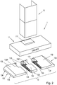
- FIG. 1 an embodiment of the extractor hood 1 according to the invention is shown schematically.
- the extractor hood 1 represents in the embodiment shown a so-called box-Esse dar.
- the hood 1 has a chimney 10 and a below the chimney 10 subsequent viewing hood 11.
- In the chimney 10 is a fan (in FIG. 1 not visible).
- a filter assembly 13 is introduced from below.
- the filter assembly 13 is in the illustrated embodiment of three parts.
- the filter device 130 consists in each case of a filter element 131 and a filter cover 136.
- the filter cover comprises in the illustrated embodiment a filter frame 134 with air guide element 132. Between the top of the filter element 131 and the air guide element 132 of the respective filter device 130, an air guide chamber 133 is formed.
- the side filter devices 130 in this case have such a structure that the filter frame 134 surrounds the flat filter element 131 on three sides. From the edge of the filter element 131, the filter frame 134 extends upwards and merges into the air guide element 132.
- the air guide element 132 is designed in one piece with the filter frame 134. In the illustrated embodiment, the filter frame 134 has a greater height at the rear edge than at the front edge.
- the air guide 132 forms an inclined plane which is inclined from the front edge of the filter element 131 to the rear edge of the filter element 131 upwards.
- a recess 1320 is introduced in the air guide element 132 in the rear region at the edge.
- the entire filter element 131 is covered by the air guide element 132, except for the area below the recess 1320.
- the filter frame 134 is provided at the front edge and the rear edge of the flat filter element 131. Between the front and rear edge of the filter element 131 extends the one with the filter frame 134 ausgestaltetes air guide 132 in the form of a flat, inclined plate arranged.
- the inclination of the air guide element 132 of the central filter device 130 corresponds to the inclination of the air guide elements 132 of the lateral filter devices 130.
- a respective recess 1320 is provided on the two open sides of the filter device 130.
- the size and position of the recesses 1320 corresponds to the size and Position of the recesses 1320 in the right and left filter device 130. Between the recesses 1320, a web 1321 remains.
- the recesses 1320 on the central filter device 130 are separated from the material of the air guiding element 132 by a web 1321.
- two air outlet openings 135 of the filter arrangement 13 are.
- the air outlet openings 135 are aligned with a passage opening 111 in the top of the viewing hood 11.
- the size of the passage opening 111 corresponds to the size of the two air outlet openings 135 and the intermediate web 1321.
- the filter assembly 13 also includes three filter devices 130.
- the width of the three filter devices 130 is the same in this embodiment.
- cover parts 1322 are provided on the side filter devices 130 in the recesses 1320, which cover part of the surface of the recess 1320 formed in the air guide element 132.
- the cover parts 1322 are provided in the recesses 1320 so that the open part of the recess 1320 continues to be on the open side of the filter device 130, that is, the side facing the further filter device 130.
- the central filter device 130 can be recessed. There are thus only the two lateral filter devices 130 introduced into the hood. Since the cover parts 1322 would make the remaining air outlet opening 135 between them too small, in this embodiment of the filter arrangement 13, the cover parts 1322 can be removed from the recesses 1320, in particular broken out. Thus, the entire surfaces of the two recesses 1320 are available as an air outlet opening 135 of the filter arrangement 13 consisting of two filter devices 130.
- the filter element 131 is held in the filter frame 134 of the filter cover 136.
- the filter frame 134 in turn is attached to the air intake opening 110 in the underside of the viewing hood 11.
- one or more fixed pins or hooks may be provided on the rear side of the individual filter devices 130.
- At the front of the filter devices 130 may then be provided corresponding fastening means 137, for example in the form of retractable pins or hooks.
- the filter assembly 13 is not connected to the top of the viewing hood 11.
- the air outlet opening 135 of the filter device abuts against the passage opening 111 of the viewing hood 11.
- the interior of the viewing hood 11 is delimited from the air guide 133 of the filter assembly 13. Via the air outlet opening 135 and the passage opening 111, air can thus pass from the air guide region 133 into the fan housing 120, in which the fan 120 is provided.
- the entire filter arrangement 13 can be removed as a part or at least in each case the individual filter devices 130 of the filter arrangement 13 in each case as a unit from the extractor hood 1 and in particular the viewing hood 11.
- the filter element 131 is taken out of the extractor hood 1 together with the filter cover 136, which comprises the filter frame 134 and the air guide element 132. This is in FIG. 5 indicated schematically.
- the thus removed filter device 130 or filter devices 130 can be cleaned, for example, in a dishwasher.
- FIG. 5 consists of the viewing hood in the embodiment shown exclusively from the outer panel.
- An inner lining of the viewing hood is not required in the extractor hood 1 according to the invention, since the one or more of the air guide elements 132 of the filter assembly 13 take over this function.
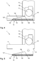
- FIG. 6 is a schematic sectional view of another embodiment of a filter assembly 13 according to the invention shown. Notwithstanding the in FIGS. 4 and 5 shown embodiment is in the embodiment of the filter assembly 13 after FIG. 6 a filter frame 134 is provided, which extends along the side of the filter element 131 and on the underside of the filter element 131 has an inwardly bent edge.
- the filter element 131 which in FIG. 6 is present as a frameless filter element 131 is thus held in the filter frame 134 and can be inserted, for example, in this inseparably connected, for example, injected.
- the further construction of the filter assembly 13 corresponds to that in the FIGS. 4 and 5 shown embodiment.
- the attachment means 137 which is preferably provided in the region of the filter element 131 is not shown. But is also preferred in the embodiment according to FIG. 6 a fastening means 137, for example in the form of retractable locking pins provided.
- FIG. 7 a further embodiment of a filter assembly 13 according to the invention is shown in a schematic sectional view.
- This embodiment corresponds to the in FIG. 6 shown embodiment and differs from this only by the filter element 131 used.
- the filter element 131 is a filter element 131 with element frame 1310.
- the filter element 131 is held over the element frame 1310 in the filter frame 134 and can for example be inserted into this or inextricably linked thereto, for example injected.
- fasteners 137 are preferably provided on this embodiment of the filter assembly 13, in the FIG. 7 but not shown.
- an extractor hood in the form of a so-called box hood, wherein the viewing hood has a box shape can be used.
- This box hood can be configured without a so-called inner frame, that is, in the field of the viewing hood only from the outer wall of the viewing hood - possibly with light bar and controls - exist.
- the filter assembly according to the invention can be introduced or inserted from below.
- the filter material which may also be referred to as filter medium
- a filter cover which may also be referred to as a hood-like apron, preferably inseparably connected to a kind of cartridge.
- This apron is designed under aerodynamic aspects.
- a left and a right filter cartridge together in a 60cm hood that is a hood with a width of the viewing hood of 60 cm, be installed.
- the three different filter cartridges fit together, for example, in a 90cm hood and two middle and the respective side filter cartridges, a 120cm hood can be displayed.
- the use of the filter arrangement according to the invention facilitates the cleaning of, for example, standard / design hoods and has an increased grease filter property.
- no cumbersome cleaning of the hood interior is necessary because it can no longer pollute.
- the filter element can be cleaned in the dishwasher together with the soiled filter cover, which is also referred to as an apron.
- the noise can be reduced because dishwashing machine-resistant insulating material with in the air guide, which can also be referred to as a filter room or filter interior, can be introduced, can be introduced.
Claims (11)
- Agencement de filtre pour une hotte aspirante (1), lequel présente au moins un dispositif de filtrage (130) comprenant au moins un élément filtrant (131), le dispositif de filtrage (130) présentant un revêtement de filtre (136) pour l'au moins un élément filtrant (130), lequel revêtement de filtre comprend au moins un élément de guidage d'air (132) qui est relié à l'élément filtrant (131), un espace de guidage d'air (133) étant formé entre le côté supérieur de l'au moins un élément filtrant (131) et l'élément de guidage d'air (132), le dispositif de filtrage (130) présentant des moyens de fixation (137) pour la fixation amovible du dispositif de filtrage (130) sur une hotte aspirante (1), et le revêtement de filtre (136) servant au guidage d'air ciblé de l'air du côté supérieur de l'élément filtrant (131) vers une ouverture de sortie d'air (135) de l'agencement de filtre (13) au moins dans la partie de l'élément de guidage d'air (132), caractérisé en ce que le dispositif de filtrage (130) est une unité pré-assemblée et en ce que l'élément filtrant (131) est relié de manière inamovible au revêtement de filtre (136) du dispositif de filtrage (130).
- Agencement de filtre selon la revendication 1,
caractérisé en ce
que les moyens de fixation (137) sont ménagés sur le dispositif de filtrage (130) dans la partie de l'élément filtrant (131) pour la fixation amovible du dispositif de filtrage (130) sur la hotte aspirante (1). - Agencement de filtre selon l'une quelconque des revendications 1 à 2,
caractérisé en ce
que l'élément de guidage d'air (132) s'étend vers le haut depuis au moins une partie du bord de l'élément filtrant (131) et est orienté de préférence au moins en partie de manière inclinée vers la surface de l'élément filtrant (131). - Agencement de filtre selon l'une quelconque des revendications 1 à 3,
caractérisé en ce
que l'élément de guidage d'air (132), en projection verticale sur l'élément filtrant (131), recouvre une partie de la surface de l'élément filtrant (131) et en ce qu'au moins un évidement (1320) est ménagé dans l'élément de guidage d'air (132), lequel forme au moins une partie d'une ouverture de sortie d'air (135) de l'agencement de filtre (13). - Agencement de filtre selon l'une quelconque des revendications 1 à 4,
caractérisé en ce
que l'élément de guidage d'air (132) s'étend d'au moins un bord, de préférence d'au moins deux bords, de l'élément filtrant (132). - Agencement de filtre selon l'une quelconque des revendications 1 à 5,
caractérisé en ce
que le revêtement de filtre (136) comprend un cadre de filtre (134) et en ce que l'élément de guidage d'air (132) est conçu d'une seule pièce avec le cadre de filtre (134). - Agencement de filtre selon l'une quelconque des revendications 1 à 6,
caractérisé en ce
qu'une matière isolante est ménagée au moins par endroits dans au moins un dispositif de filtrage (130). - Hotte aspirante, caractérisée en ce qu'un agencement de filtre (13) selon l'une quelconque des revendications 1 à 7 est disposé dans la hotte aspirante.
- Hotte aspirante selon la revendication 8,
caractérisée en ce
qu'un agencement de filtre (13) comprenant au moins deux dispositifs de filtrage (130) est disposé dans la hotte aspirante (1), les dispositifs de filtrage (130) étant situés de manière avoisinante l'un à l'autre et les espaces de guidage d'air (133) des au moins deux dispositifs de filtrage (130) passant l'un dans l'autre. - Hotte aspirante selon l'une quelconque des revendications 8 ou 9,
caractérisée en ce
que deux dispositifs de filtrage (130) latéraux et un dispositif de filtrage (130) central sont ménagés et en ce que les dispositifs de filtrage (130) latéraux se distinguent du dispositif de filtrage (130) central au moins dans leur forme. - Hotte aspirante selon l'une quelconque des revendications 8 à 10,
caractérisée en ce
que celle-ci présente une calotte de visibilité (11) dont le corps est formé uniquement de la matière extérieure de la calotte de visibilité (11) et en ce que l'agencement de filtre (13) est fixé de manière amovible dans la calotte de visibilité (11).
Priority Applications (1)
| Application Number | Priority Date | Filing Date | Title |
|---|---|---|---|
| EP18154919.7A EP3346195B1 (fr) | 2014-05-26 | 2015-04-28 | Système de filtre pour hotte aspirante et hotte aspirante |
Applications Claiming Priority (1)
| Application Number | Priority Date | Filing Date | Title |
|---|---|---|---|
| DE102014209953.6A DE102014209953A1 (de) | 2014-05-26 | 2014-05-26 | Filteranordung für Dunstabzugshaube und Dunstabzugshaube |
Related Child Applications (2)
| Application Number | Title | Priority Date | Filing Date |
|---|---|---|---|
| EP18154919.7A Division EP3346195B1 (fr) | 2014-05-26 | 2015-04-28 | Système de filtre pour hotte aspirante et hotte aspirante |
| EP18154919.7A Division-Into EP3346195B1 (fr) | 2014-05-26 | 2015-04-28 | Système de filtre pour hotte aspirante et hotte aspirante |
Publications (2)
| Publication Number | Publication Date |
|---|---|
| EP2952819A1 EP2952819A1 (fr) | 2015-12-09 |
| EP2952819B1 true EP2952819B1 (fr) | 2018-10-24 |
Family
ID=53008370
Family Applications (2)
| Application Number | Title | Priority Date | Filing Date |
|---|---|---|---|
| EP15165448.0A Active EP2952819B1 (fr) | 2014-05-26 | 2015-04-28 | Système de filtre pour hotte aspirante et hotte aspirante |
| EP18154919.7A Active EP3346195B1 (fr) | 2014-05-26 | 2015-04-28 | Système de filtre pour hotte aspirante et hotte aspirante |
Family Applications After (1)
| Application Number | Title | Priority Date | Filing Date |
|---|---|---|---|
| EP18154919.7A Active EP3346195B1 (fr) | 2014-05-26 | 2015-04-28 | Système de filtre pour hotte aspirante et hotte aspirante |
Country Status (4)
| Country | Link |
|---|---|
| EP (2) | EP2952819B1 (fr) |
| DE (1) | DE102014209953A1 (fr) |
| ES (1) | ES2701830T3 (fr) |
| TR (1) | TR201816491T4 (fr) |
Families Citing this family (3)
| Publication number | Priority date | Publication date | Assignee | Title |
|---|---|---|---|---|
| DE102016203783A1 (de) | 2016-03-08 | 2017-09-14 | BSH Hausgeräte GmbH | Filterelement für Dunstabzugshaube |
| DE102016204819A1 (de) * | 2016-03-23 | 2017-09-28 | BSH Hausgeräte GmbH | Dunstabzugshaube mit Sichthaube und Innenelement |
| DE202017003105U1 (de) | 2017-06-13 | 2017-06-29 | BSH Hausgeräte GmbH | Filterelement für Dunstabzugshaube |
Family Cites Families (3)
| Publication number | Priority date | Publication date | Assignee | Title |
|---|---|---|---|---|
| WO2005084722A1 (fr) * | 2004-03-02 | 2005-09-15 | Garland Commercial Ranges Limited | Systeme de ventilation par ultraviolets dote d'un dispositif de filtration ameliore |
| DE102007047197A1 (de) * | 2007-10-02 | 2009-04-09 | Homeier Küchentechnik GmbH | Verfahren und Vorrichtung zum Absaugen von Dunst, insbesondere Küchendunst |
| DE102009028808A1 (de) * | 2009-08-21 | 2011-02-24 | BSH Bosch und Siemens Hausgeräte GmbH | Innenrahmen für Dunstabzugshaube und Dunstabzugshaube |
-
2014
- 2014-05-26 DE DE102014209953.6A patent/DE102014209953A1/de not_active Withdrawn
-
2015
- 2015-04-28 EP EP15165448.0A patent/EP2952819B1/fr active Active
- 2015-04-28 EP EP18154919.7A patent/EP3346195B1/fr active Active
- 2015-04-28 ES ES15165448T patent/ES2701830T3/es active Active
- 2015-04-28 TR TR2018/16491T patent/TR201816491T4/tr unknown
Non-Patent Citations (1)
| Title |
|---|
| None * |
Also Published As
| Publication number | Publication date |
|---|---|
| ES2701830T3 (es) | 2019-02-26 |
| EP3346195A1 (fr) | 2018-07-11 |
| EP3346195B1 (fr) | 2020-08-26 |
| TR201816491T4 (tr) | 2018-11-21 |
| DE102014209953A1 (de) | 2015-11-26 |
| EP2952819A1 (fr) | 2015-12-09 |
Similar Documents
| Publication | Publication Date | Title |
|---|---|---|
| EP3775700B1 (fr) | Dispositif d'évacuation de fumée comprenant un dispositif de filtrage | |
| EP1890789B1 (fr) | Systeme filtrant d'une hotte aspirante | |
| DE102008020149A1 (de) | Filtereinheit für eine Dunstabzugsvorrichtung und Dunstabzugsvorrichtung | |
| WO2017080781A1 (fr) | Dispositif de filtration pour dispositif d'aspiration de fumées et dispositif d'aspiration de fumées | |
| EP3287701B1 (fr) | Appareil combiné comprenant une plaque de cuisson et une extracteur de fumées | |
| DE202018006721U1 (de) | Dunstabzug zum Abzug von auf einem Kochfeld erzeugter Abluft in vertikal unterhalb einer Kochfeldebene weisender Richtung | |
| EP2952819B1 (fr) | Système de filtre pour hotte aspirante et hotte aspirante | |
| EP2469187A1 (fr) | Unité de filtre pour une hotte aspirante | |
| EP3336438B1 (fr) | Hotte aspirante | |
| EP2772695B1 (fr) | Hotte aspirante | |
| EP3222919B1 (fr) | Hotte aspirante comprenant un couvercle transparent et élément interne | |
| EP2420736A1 (fr) | Unité de filtre pour une hotte aspirante et hotte aspirante | |
| EP2144011B1 (fr) | Dispositif d'aspiration de vapeur | |
| EP3956611A1 (fr) | Dispositif de filtrage pour un dispositif d'extraction de fumées et dispositif d'extraction de fumées avec dispositif de filtrage | |
| DE102018215480A1 (de) | Dunstabzugsvorrichtung mit Verschlussklappe | |
| EP2615383B1 (fr) | Hotte aspirante | |
| DE102012200284B4 (de) | Umluftmodul für Kamin einer Dunstabzugshaube | |
| DE102004043069A1 (de) | Dunstabzugshaube | |
| EP2827066B1 (fr) | Hotte aspirante | |
| EP2803913B1 (fr) | Élément de filtre pour hotte aspirante et hotte aspirante | |
| EP2554915A2 (fr) | Porte-filtre pour élément de filtre à odeurs et hotte aspirante | |
| DE102013200104B4 (de) | Dunstabzugshaube mit Kamin und Geruchsfilter | |
| EP2985534A1 (fr) | Élément plat et hotte aspirante | |
| EP3926242A1 (fr) | Unité de filtre et hotte aspirante | |
| EP3018421A1 (fr) | Équilibrage de tolérance de filtres |
Legal Events
| Date | Code | Title | Description |
|---|---|---|---|
| PUAI | Public reference made under article 153(3) epc to a published international application that has entered the european phase |
Free format text: ORIGINAL CODE: 0009012 |
|
| AK | Designated contracting states |
Kind code of ref document: A1 Designated state(s): AL AT BE BG CH CY CZ DE DK EE ES FI FR GB GR HR HU IE IS IT LI LT LU LV MC MK MT NL NO PL PT RO RS SE SI SK SM TR |
|
| AX | Request for extension of the european patent |
Extension state: BA ME |
|
| 17P | Request for examination filed |
Effective date: 20160609 |
|
| RBV | Designated contracting states (corrected) |
Designated state(s): AL AT BE BG CH CY CZ DE DK EE ES FI FR GB GR HR HU IE IS IT LI LT LU LV MC MK MT NL NO PL PT RO RS SE SI SK SM TR |
|
| GRAP | Despatch of communication of intention to grant a patent |
Free format text: ORIGINAL CODE: EPIDOSNIGR1 |
|
| STAA | Information on the status of an ep patent application or granted ep patent |
Free format text: STATUS: GRANT OF PATENT IS INTENDED |
|
| INTG | Intention to grant announced |
Effective date: 20180524 |
|
| GRAS | Grant fee paid |
Free format text: ORIGINAL CODE: EPIDOSNIGR3 |
|
| GRAA | (expected) grant |
Free format text: ORIGINAL CODE: 0009210 |
|
| STAA | Information on the status of an ep patent application or granted ep patent |
Free format text: STATUS: THE PATENT HAS BEEN GRANTED |
|
| AK | Designated contracting states |
Kind code of ref document: B1 Designated state(s): AL AT BE BG CH CY CZ DE DK EE ES FI FR GB GR HR HU IE IS IT LI LT LU LV MC MK MT NL NO PL PT RO RS SE SI SK SM TR |
|
| REG | Reference to a national code |
Ref country code: CH Ref legal event code: EP |
|
| REG | Reference to a national code |
Ref country code: IE Ref legal event code: FG4D Free format text: LANGUAGE OF EP DOCUMENT: GERMAN |
|
| REG | Reference to a national code |
Ref country code: AT Ref legal event code: REF Ref document number: 1057135 Country of ref document: AT Kind code of ref document: T Effective date: 20181115 |
|
| REG | Reference to a national code |
Ref country code: DE Ref legal event code: R096 Ref document number: 502015006549 Country of ref document: DE |
|
| REG | Reference to a national code |
Ref country code: ES Ref legal event code: FG2A Ref document number: 2701830 Country of ref document: ES Kind code of ref document: T3 Effective date: 20190226 |
|
| REG | Reference to a national code |
Ref country code: NL Ref legal event code: MP Effective date: 20181024 |
|
| REG | Reference to a national code |
Ref country code: LT Ref legal event code: MG4D |
|
| PG25 | Lapsed in a contracting state [announced via postgrant information from national office to epo] |
Ref country code: NL Free format text: LAPSE BECAUSE OF FAILURE TO SUBMIT A TRANSLATION OF THE DESCRIPTION OR TO PAY THE FEE WITHIN THE PRESCRIBED TIME-LIMIT Effective date: 20181024 |
|
| PG25 | Lapsed in a contracting state [announced via postgrant information from national office to epo] |
Ref country code: LV Free format text: LAPSE BECAUSE OF FAILURE TO SUBMIT A TRANSLATION OF THE DESCRIPTION OR TO PAY THE FEE WITHIN THE PRESCRIBED TIME-LIMIT Effective date: 20181024 Ref country code: FI Free format text: LAPSE BECAUSE OF FAILURE TO SUBMIT A TRANSLATION OF THE DESCRIPTION OR TO PAY THE FEE WITHIN THE PRESCRIBED TIME-LIMIT Effective date: 20181024 Ref country code: LT Free format text: LAPSE BECAUSE OF FAILURE TO SUBMIT A TRANSLATION OF THE DESCRIPTION OR TO PAY THE FEE WITHIN THE PRESCRIBED TIME-LIMIT Effective date: 20181024 Ref country code: HR Free format text: LAPSE BECAUSE OF FAILURE TO SUBMIT A TRANSLATION OF THE DESCRIPTION OR TO PAY THE FEE WITHIN THE PRESCRIBED TIME-LIMIT Effective date: 20181024 Ref country code: PL Free format text: LAPSE BECAUSE OF FAILURE TO SUBMIT A TRANSLATION OF THE DESCRIPTION OR TO PAY THE FEE WITHIN THE PRESCRIBED TIME-LIMIT Effective date: 20181024 Ref country code: BG Free format text: LAPSE BECAUSE OF FAILURE TO SUBMIT A TRANSLATION OF THE DESCRIPTION OR TO PAY THE FEE WITHIN THE PRESCRIBED TIME-LIMIT Effective date: 20190124 Ref country code: IS Free format text: LAPSE BECAUSE OF FAILURE TO SUBMIT A TRANSLATION OF THE DESCRIPTION OR TO PAY THE FEE WITHIN THE PRESCRIBED TIME-LIMIT Effective date: 20190224 Ref country code: NO Free format text: LAPSE BECAUSE OF FAILURE TO SUBMIT A TRANSLATION OF THE DESCRIPTION OR TO PAY THE FEE WITHIN THE PRESCRIBED TIME-LIMIT Effective date: 20190124 |
|
| PG25 | Lapsed in a contracting state [announced via postgrant information from national office to epo] |
Ref country code: RS Free format text: LAPSE BECAUSE OF FAILURE TO SUBMIT A TRANSLATION OF THE DESCRIPTION OR TO PAY THE FEE WITHIN THE PRESCRIBED TIME-LIMIT Effective date: 20181024 Ref country code: PT Free format text: LAPSE BECAUSE OF FAILURE TO SUBMIT A TRANSLATION OF THE DESCRIPTION OR TO PAY THE FEE WITHIN THE PRESCRIBED TIME-LIMIT Effective date: 20190224 Ref country code: GR Free format text: LAPSE BECAUSE OF FAILURE TO SUBMIT A TRANSLATION OF THE DESCRIPTION OR TO PAY THE FEE WITHIN THE PRESCRIBED TIME-LIMIT Effective date: 20190125 Ref country code: AL Free format text: LAPSE BECAUSE OF FAILURE TO SUBMIT A TRANSLATION OF THE DESCRIPTION OR TO PAY THE FEE WITHIN THE PRESCRIBED TIME-LIMIT Effective date: 20181024 Ref country code: SE Free format text: LAPSE BECAUSE OF FAILURE TO SUBMIT A TRANSLATION OF THE DESCRIPTION OR TO PAY THE FEE WITHIN THE PRESCRIBED TIME-LIMIT Effective date: 20181024 |
|
| REG | Reference to a national code |
Ref country code: DE Ref legal event code: R097 Ref document number: 502015006549 Country of ref document: DE |
|
| PG25 | Lapsed in a contracting state [announced via postgrant information from national office to epo] |
Ref country code: CZ Free format text: LAPSE BECAUSE OF FAILURE TO SUBMIT A TRANSLATION OF THE DESCRIPTION OR TO PAY THE FEE WITHIN THE PRESCRIBED TIME-LIMIT Effective date: 20181024 Ref country code: DK Free format text: LAPSE BECAUSE OF FAILURE TO SUBMIT A TRANSLATION OF THE DESCRIPTION OR TO PAY THE FEE WITHIN THE PRESCRIBED TIME-LIMIT Effective date: 20181024 |
|
| PG25 | Lapsed in a contracting state [announced via postgrant information from national office to epo] |
Ref country code: SM Free format text: LAPSE BECAUSE OF FAILURE TO SUBMIT A TRANSLATION OF THE DESCRIPTION OR TO PAY THE FEE WITHIN THE PRESCRIBED TIME-LIMIT Effective date: 20181024 Ref country code: EE Free format text: LAPSE BECAUSE OF FAILURE TO SUBMIT A TRANSLATION OF THE DESCRIPTION OR TO PAY THE FEE WITHIN THE PRESCRIBED TIME-LIMIT Effective date: 20181024 Ref country code: SK Free format text: LAPSE BECAUSE OF FAILURE TO SUBMIT A TRANSLATION OF THE DESCRIPTION OR TO PAY THE FEE WITHIN THE PRESCRIBED TIME-LIMIT Effective date: 20181024 Ref country code: RO Free format text: LAPSE BECAUSE OF FAILURE TO SUBMIT A TRANSLATION OF THE DESCRIPTION OR TO PAY THE FEE WITHIN THE PRESCRIBED TIME-LIMIT Effective date: 20181024 |
|
| PLBE | No opposition filed within time limit |
Free format text: ORIGINAL CODE: 0009261 |
|
| STAA | Information on the status of an ep patent application or granted ep patent |
Free format text: STATUS: NO OPPOSITION FILED WITHIN TIME LIMIT |
|
| 26N | No opposition filed |
Effective date: 20190725 |
|
| PG25 | Lapsed in a contracting state [announced via postgrant information from national office to epo] |
Ref country code: SI Free format text: LAPSE BECAUSE OF FAILURE TO SUBMIT A TRANSLATION OF THE DESCRIPTION OR TO PAY THE FEE WITHIN THE PRESCRIBED TIME-LIMIT Effective date: 20181024 |
|
| REG | Reference to a national code |
Ref country code: CH Ref legal event code: PL |
|
| REG | Reference to a national code |
Ref country code: BE Ref legal event code: MM Effective date: 20190430 |
|
| PG25 | Lapsed in a contracting state [announced via postgrant information from national office to epo] |
Ref country code: LU Free format text: LAPSE BECAUSE OF NON-PAYMENT OF DUE FEES Effective date: 20190428 Ref country code: MC Free format text: LAPSE BECAUSE OF FAILURE TO SUBMIT A TRANSLATION OF THE DESCRIPTION OR TO PAY THE FEE WITHIN THE PRESCRIBED TIME-LIMIT Effective date: 20181024 |
|
| PG25 | Lapsed in a contracting state [announced via postgrant information from national office to epo] |
Ref country code: CH Free format text: LAPSE BECAUSE OF NON-PAYMENT OF DUE FEES Effective date: 20190430 Ref country code: LI Free format text: LAPSE BECAUSE OF NON-PAYMENT OF DUE FEES Effective date: 20190430 |
|
| PG25 | Lapsed in a contracting state [announced via postgrant information from national office to epo] |
Ref country code: BE Free format text: LAPSE BECAUSE OF NON-PAYMENT OF DUE FEES Effective date: 20190430 |
|
| PG25 | Lapsed in a contracting state [announced via postgrant information from national office to epo] |
Ref country code: IE Free format text: LAPSE BECAUSE OF NON-PAYMENT OF DUE FEES Effective date: 20190428 |
|
| PG25 | Lapsed in a contracting state [announced via postgrant information from national office to epo] |
Ref country code: CY Free format text: LAPSE BECAUSE OF FAILURE TO SUBMIT A TRANSLATION OF THE DESCRIPTION OR TO PAY THE FEE WITHIN THE PRESCRIBED TIME-LIMIT Effective date: 20181024 |
|
| REG | Reference to a national code |
Ref country code: AT Ref legal event code: MM01 Ref document number: 1057135 Country of ref document: AT Kind code of ref document: T Effective date: 20200428 |
|
| PG25 | Lapsed in a contracting state [announced via postgrant information from national office to epo] |
Ref country code: MT Free format text: LAPSE BECAUSE OF FAILURE TO SUBMIT A TRANSLATION OF THE DESCRIPTION OR TO PAY THE FEE WITHIN THE PRESCRIBED TIME-LIMIT Effective date: 20181024 Ref country code: HU Free format text: LAPSE BECAUSE OF FAILURE TO SUBMIT A TRANSLATION OF THE DESCRIPTION OR TO PAY THE FEE WITHIN THE PRESCRIBED TIME-LIMIT; INVALID AB INITIO Effective date: 20150428 |
|
| PG25 | Lapsed in a contracting state [announced via postgrant information from national office to epo] |
Ref country code: AT Free format text: LAPSE BECAUSE OF NON-PAYMENT OF DUE FEES Effective date: 20200428 |
|
| PG25 | Lapsed in a contracting state [announced via postgrant information from national office to epo] |
Ref country code: MK Free format text: LAPSE BECAUSE OF FAILURE TO SUBMIT A TRANSLATION OF THE DESCRIPTION OR TO PAY THE FEE WITHIN THE PRESCRIBED TIME-LIMIT Effective date: 20181024 |
|
| PGFP | Annual fee paid to national office [announced via postgrant information from national office to epo] |
Ref country code: IT Payment date: 20230428 Year of fee payment: 9 Ref country code: FR Payment date: 20230417 Year of fee payment: 9 Ref country code: ES Payment date: 20230517 Year of fee payment: 9 Ref country code: DE Payment date: 20230430 Year of fee payment: 9 |
|
| PGFP | Annual fee paid to national office [announced via postgrant information from national office to epo] |
Ref country code: TR Payment date: 20230426 Year of fee payment: 9 |
|
| PGFP | Annual fee paid to national office [announced via postgrant information from national office to epo] |
Ref country code: GB Payment date: 20230420 Year of fee payment: 9 |