EP2950155B1 - Image forming apparatus - Google Patents
Image forming apparatus Download PDFInfo
- Publication number
- EP2950155B1 EP2950155B1 EP15168004.8A EP15168004A EP2950155B1 EP 2950155 B1 EP2950155 B1 EP 2950155B1 EP 15168004 A EP15168004 A EP 15168004A EP 2950155 B1 EP2950155 B1 EP 2950155B1
- Authority
- EP
- European Patent Office
- Prior art keywords
- recording medium
- secondary transfer
- nip
- thickness
- contact
- Prior art date
- Legal status (The legal status is an assumption and is not a legal conclusion. Google has not performed a legal analysis and makes no representation as to the accuracy of the status listed.)
- Active
Links
Images


Classifications
-
- G—PHYSICS
- G03—PHOTOGRAPHY; CINEMATOGRAPHY; ANALOGOUS TECHNIQUES USING WAVES OTHER THAN OPTICAL WAVES; ELECTROGRAPHY; HOLOGRAPHY
- G03G—ELECTROGRAPHY; ELECTROPHOTOGRAPHY; MAGNETOGRAPHY
- G03G15/00—Apparatus for electrographic processes using a charge pattern
- G03G15/14—Apparatus for electrographic processes using a charge pattern for transferring a pattern to a second base
- G03G15/16—Apparatus for electrographic processes using a charge pattern for transferring a pattern to a second base of a toner pattern, e.g. a powder pattern, e.g. magnetic transfer
- G03G15/1665—Apparatus for electrographic processes using a charge pattern for transferring a pattern to a second base of a toner pattern, e.g. a powder pattern, e.g. magnetic transfer by introducing the second base in the nip formed by the recording member and at least one transfer member, e.g. in combination with bias or heat
-
- G—PHYSICS
- G03—PHOTOGRAPHY; CINEMATOGRAPHY; ANALOGOUS TECHNIQUES USING WAVES OTHER THAN OPTICAL WAVES; ELECTROGRAPHY; HOLOGRAPHY
- G03G—ELECTROGRAPHY; ELECTROPHOTOGRAPHY; MAGNETOGRAPHY
- G03G15/00—Apparatus for electrographic processes using a charge pattern
- G03G15/14—Apparatus for electrographic processes using a charge pattern for transferring a pattern to a second base
- G03G15/16—Apparatus for electrographic processes using a charge pattern for transferring a pattern to a second base of a toner pattern, e.g. a powder pattern, e.g. magnetic transfer
- G03G15/1605—Apparatus for electrographic processes using a charge pattern for transferring a pattern to a second base of a toner pattern, e.g. a powder pattern, e.g. magnetic transfer using at least one intermediate support
-
- G—PHYSICS
- G03—PHOTOGRAPHY; CINEMATOGRAPHY; ANALOGOUS TECHNIQUES USING WAVES OTHER THAN OPTICAL WAVES; ELECTROGRAPHY; HOLOGRAPHY
- G03G—ELECTROGRAPHY; ELECTROPHOTOGRAPHY; MAGNETOGRAPHY
- G03G2215/00—Apparatus for electrophotographic processes
- G03G2215/00362—Apparatus for electrophotographic processes relating to the copy medium handling
- G03G2215/00535—Stable handling of copy medium
- G03G2215/00717—Detection of physical properties
- G03G2215/00738—Detection of physical properties of sheet thickness or rigidity
-
- G—PHYSICS
- G03—PHOTOGRAPHY; CINEMATOGRAPHY; ANALOGOUS TECHNIQUES USING WAVES OTHER THAN OPTICAL WAVES; ELECTROGRAPHY; HOLOGRAPHY
- G03G—ELECTROGRAPHY; ELECTROPHOTOGRAPHY; MAGNETOGRAPHY
- G03G2215/00—Apparatus for electrophotographic processes
- G03G2215/01—Apparatus for electrophotographic processes for producing multicoloured copies
- G03G2215/019—Structural features of the multicolour image forming apparatus
- G03G2215/0193—Structural features of the multicolour image forming apparatus transfer member separable from recording member
Definitions
- Exemplary aspects of the present disclosure generally relate to a transfer device and an image forming apparatus including the transfer device, and more particularly to an image forming apparatus such as a copier, a facsimile machine, and a printer.
- An image forming apparatus equipped with a transfer device that transfers a toner image from an image bearer onto a recording medium interposed in a so-called transfer nip at which the image bearer and a nip forming device contact.
- a transfer bias is applied to the transfer nip by a transfer bias power source to transfer the toner image from the image bearer onto the recording medium.
- a secondary transfer device is known to transfer secondarily a composite toner image formed on an intermediate transfer belt onto the recording medium.
- toner images formed on a plurality of photoconductors are transferred onto the intermediate transfer belt in primary transfer nips at which the photoconductors and the intermediate transfer belt contact such that the toner images are superimposed one atop the other, thereby forming the composite toner image.
- the composite toner image is then transferred secondarily from the intermediate transfer belt to the recording medium by the secondary transfer device.
- the secondary transfer device includes a secondary transfer roller as a nip forming device and a secondary-transfer opposed roller.
- the secondary transfer roller contacts the intermediate transfer belt serving as the image bearer.
- the secondary-transfer opposed roller is disposed opposite the secondary transfer roller via the intermediate transfer belt and contacts the intermediate transfer belt from the back thereof.
- the intermediate transfer belt is interposed between the secondary transfer roller and the secondary-transfer opposed roller to form a secondary transfer nip.
- the traveling speed of the intermediate transfer belt changes suddenly which then causes an image to be transferred onto the intermediate transfer belt from the photoconductor in the primary transfer nip to stretch or shrink undesirably.
- the density of toner changes at a place where the density is expected to be constant, thereby generating undesirable streaking or a so-called shock jitter.
- a known image forming apparatus includes a contact-and-separation device that moves an intermediate transfer belt and a secondary transfer roller to contact and separate from each other.
- a contact-and-separation device that moves an intermediate transfer belt and a secondary transfer roller to contact and separate from each other.
- an eccentric cam of the contact-and-separation device separates the secondary transfer roller from the intermediate transfer belt. Accordingly, the secondary transfer roller and the intermediate transfer belt are separated, and a certain space is formed therebetween, hence reducing shock jitter when the recording medium enters the secondary transfer nip.
- the secondary transfer roller is released by the eccentric cam and is pushed against the intermediate transfer belt by a spring.
- the secondary transfer roller contacts the intermediate transfer belt, and adequate transfer pressure is obtained at the secondary transfer nip during transfer, thereby preventing transfer failure.
- the eccentric cam of the contact-and-separation device separates the secondary transfer roller from the intermediate transfer belt by the same predetermined amount.
- the secondary transfer roller and the intermediate transfer belt are separated when the recording medium exits the secondary transfer nip, hence reducing shock jitter when the recording medium exits the secondary transfer nip.
- the intermediate transfer belt and the secondary transfer roller are spaced apart a certain distance such that the impact is reduced as much as possible when the intermediate transfer belt and the secondary transfer roller come in contact and the transfer pressure is zero in accordance with a thickness of the recording medium when the recording medium enters and exits the secondary transfer nip.
- the impact is reduced when the intermediate transfer belt and the secondary transfer roller come in contact and hence shock jitter is reduced without separating the intermediate transfer belt and the secondary transfer roller in accordance with the thickness of the recording medium more than necessary.
- the recording media When performing continuous printing in which images are formed on a plurality of recording media, the recording media generally have the same thickness, but there may be a case in which recording media with different thicknesses may be used during continuous printing.
- the thickness of a successive sheet is different from the thickness of a preceding sheet, after the preceding sheet exits the secondary transfer nip but during a time in which a sheet interval area, i.e., an area between the preceding sheet and the successive sheet, passes through the secondary transfer nip, the space between the intermediate transfer belt and the secondary transfer roller is changed in accordance with the thickness of the successive sheet.
- the interval between the preceding sheet and the successive sheet is significantly short.
- the contact-and-separation device cannot change the size of the space between the intermediate transfer belt and the secondary transfer roller in accordance with the thickness of the successive sheet while the sheet interval area between the preceding sheet and the successive sheet passes through the secondary transfer nip. That is, the space between the intermediate transfer belt and the secondary transfer roller cannot be changed before the successive sheet enters the secondary transfer nip.
- the sheet interval area between the preceding sheet and the successive sheet may be increased so that the contact-and-separation device can change the space between the intermediate transfer belt and the secondary transfer nip before the successive sheet enters the secondary transfer nip.
- a wider sheet interval area between the preceding sheet and the successive sheet decreases productivity in the continuous printing.
- EP 2 395 401 A1 relates to a transfer device and image forming apparatus incorporating transfer device.
- An image transfer system comprises an image bearer and an opposed member having a contact surface contacting a recording medium and opposed to a surface of the image bearer to form a transfer nip.
- a pressing device applies pressure to the transfer nip.
- An engaging and disengaging member engages and disengages the contact surface from the surface of the image bearer.
- a transfer bias device applies a transfer bias transferring an image formed on the image bearer onto the recording medium conveyed and pinched at the transfer nip.
- the image is composed of an adjustment pattern formed on a portion of the image bearer corresponding to an interval between recording mediums successively conveyed through the transfer nip.
- the engaging and disengaging device disengages the contact surface from the surface of the image bearer to form a gap therebetween when the adjustment pattern passes therethrough.
- a transfer device includes a moving device to move a contact surface of an opposing member toward and away from an image bearing surface of an image bearing member.
- the moving device includes a cam and a cam driving device to rotate the cam. When the cam is at a first position, the image bearing surface and the contact surface are separated. When the cam is at a second position, the image bearing surface and the contact surface contact each other.
- the cam After a recording medium enters a transfer nip between the image bearing surface and the contact surface, the cam is at the second position, and when the recording medium exits the transfer nip a timing at which the cam starts to rotate from the second position to the first position changes depending on a thickness of the recording medium, to reduce pressure in the transfer nip.
- a distance adjusting unit adjusts an inter-unit distance between a contact unit and an image carrier by moving the image carrier or the contact unit by applying an opposing force to the image carrier or the contact unit against a biasing force applied by a biasing unit based on thickness information of a recording sheet acquired by a thickness-information acquiring unit and data indicating a relationship between the thickness information and an inter-unit distance change amount stored in a data storage unit.
- An image forming apparatus includes a first rotator by which one surface of a paper is subjected to image transferring, image fixing, or other processings, a second rotator which presses the paper against the first rotator from the other surface of the paper, a space changing unit which changes a space between axial cores of the first rotator and the second rotator, a feeding unit which feeds the paper between the first rotator and the second rotator, and a control unit which adjusts a driving timing of the space changing unit in accordance with the driving of the feeding unit, wherein when the paper is thinner than a set value, the control unit makes the paper enter between both the rotators in a state where the second rotator is pressed against the first rotator, and when the paper is equal to or thicker than the set value, the control unit controls to press the second rotator against the first rotator at a timing where a distal end of the paper passes
- JP 2007-139915 A1 relates to an image forming device.
- the image forming device is provided with the secondary transfer roller bringing an intermediate transfer belt into a press-contact to the recording paper in order to transfer an image transferred to an intermediate transfer belt to the recording paper again; and a registration roller to supply the recording paper to a secondary transfer part.
- recording paper thickness detecting mechanisms for detecting the thickness of the recording paper are provided in a transporting path of the recording paper.
- the secondary transfer roller is opened or closed according to the thickness of the detected recording paper.
- shock jitter is reduced without degrading productivity during continuous printing.
- first, second, etc. may be used herein to describe various elements, components, regions, layers and/or sections, it should be understood that such elements, components, regions, layers and/or sections are not limited thereby because such terms are relative, that is, used only to distinguish one element, component, region, layer or section from another region, layer or section.
- a first element, component, region, layer or section discussed below could be termed a second element, component, region, layer or section without departing from the teachings of this disclosure.
- paper is the medium from which is made a sheet on which an image is to be formed. It should be noted, however, that other printable media are available in sheet form, and accordingly their use here is included. Thus, solely for simplicity, although this Detailed Description section refers to paper, sheets thereof, paper feeder, etc., it should be understood that the sheets, etc., are not limited only to paper, but include other printable media as well.
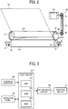
- FIG. 1 is a schematic diagram illustrating an image forming apparatus 1 according to an illustrative embodiment of the present disclosure.
- the image forming apparatus 1 illustrated in FIG. 1 is a tandem-type color image forming apparatus in which multiple image forming stations are arranged in tandem.
- the image forming apparatus 1 includes an image reader 10, an image forming unit 11, a paper feed unit 12, a transfer unit 13, a fixing unit 14, and a paper output unit 15.
- the image forming apparatus includes a controller 200.
- the image reader 10 includes an exposure glass 101, a reading device 102, a cover 103, a light source, and so forth.
- a document is placed on the exposure glass 101.
- the reading device 102 reads image information of the document on the exposure glass 101 by receiving reflected light reflected upon the document irradiated by the light source.
- the cover 103 is rotatable about a rotary shaft 103a and is openably closable.
- the cover 103 is opened, allowing the document to be placed on the exposure glass 101. After the cover 103 is closed, the light source of the image reader 10 irradiates the document with light.
- the reading device 102 consisting of a Charge Coupled Device (CCD), a Contact Image Sensors (CIS), and so forth receives light reflected upon the document, and reads color-separation signals for each of three primary colors of light, i.e., red, green, and blue.
- the image forming unit 11 includes image forming stations 110S, 110Y, 110M, 110C, and 110K, one for each of colors, special color, yellow, magenta, cyan, and black, respectively.
- the suffixes S, Y, C, M, and K denote the colors, special color, yellow, cyan, magenta, and black, respectively.
- Special color herein refers to a color that cannot be produced with the toners of yellow, cyan, magenta, and black, for example, a clear toner, metallic, white, and so forth.
- the suffixes S, Y, M, C, and K indicating colors are omitted herein unless otherwise specified.
- the image forming stations 110S, 110Y, 110M, 110C, and 110K all have the same configuration, differing only in the color of toner employed.
- the image forming stations 110S, 110Y, 110M, 110C, and 110K employ toners of different colors, that is, special color, yellow, magenta, cyan, and black, respectively.
- the image forming stations 110S, 110Y, 110M, 110C, and 110K are replaced upon reaching their product life cycles.
- Each of image forming stations 11 0S, 110Y, 110M, 110C, and 110K is detachably mountable as a process cartridge relative to a main body 2 of the image forming apparatus.
- the image forming stations 110S, 110Y, 110M, 110C, and 110K all have the same configuration, differing only in the color of toner employed. Thus, a description is provided of the image forming station 110K for forming a toner image of black as a representative example of the image forming station,
- the image forming station 110K includes a charging device 111K, a photo conductor 112K serving as an image bearer or a latent image bearer, a developing device 114K, a static eliminator 115K, a photoconductor cleaner 116K, and so forth. These devices are held in a common holder so that they are detachably attachable together and replaced at the same time.
- the photoconductor 112K includes a drum-shaped base on which an organic photosensitive layer is disposed, with the external diameter of approximately 60 mm.
- the photoconductor 112K is rotated in a counterclockwise direction by a driving device.
- the charging device 111K includes a charging wire which is a charged electrode of a charger. A charging bias is applied to the charging wire to generate electrical discharge between the charging wire and the outer peripheral surface of the photoconductor 112K. Accordingly, the surface of the photoconductor 112K is uniformly charged.
- the photoconductor 112K is uniformly charged with a negative polarity which is the same polarity as the polarity of normally-charged toner.
- a charging bias an alternating current (AC) voltage superimposed on a direct current (DC) voltage is employed.
- a charging roller that contacts the photoconductor 112K or is disposed near the photoconductor 112K is employed.
- the uniformly charged surface of the photoconductor 112K is scanned by a light beam projected from an exposure device 113, thereby forming an electrostatic latent image for black on the surface of the photoconductor 112K.
- the potential of the irradiated portion of the photoconductor 112K attenuates and becomes less than the potential of other areas, that is, the background portion (non-image portion), thereby forming the electrostatic latent image on the photoconductor 112K.
- the electrostatic latent image for black on the photoconductor 112K is developed with black toner by the developing device 114K. Accordingly, a visible image, also known as a toner image of black, is formed on the photoconductor 112K. As will be described later in detail, the toner image is transferred primarily onto an intermediate transfer belt 131 in a process known as a primary transfer process.
- the developing device 114K includes and a container that stores a two-component developing agent including black toner and carrier particles.
- a developing sleeve disposed inside the container includes a magnetic roller inside the developing sleeve. The magnetic force of the magnetic roller attracts the developing agent onto the surface of the developing sleeve.
- a developing bias having the same polarity as that of the toner is applied to the developing sleeve.
- the developing bias has a potential greater than that of the electrostatic latent image on the photoconductor 112K, but less than the charging potential of the uniformly charged photoconductor 112K.
- a developing potential that causes the toner on the developing sleeve to move electrostatically to the electrostatic latent image on the photoconductor 112K acts between the developing sleeve and the electrostatic latent image on the photoconductor 112K.
- a non-developing potential acts between the developing sleeve and the non-image formation area of the photoconductor 112, causing the toner on the developing sleeve to move to the sleeve surface.
- the toner on the developing sleeve adheres selectively to the electrostatic latent image formed on the photoconductor 112K, thereby forming a visible image, known as a toner image.
- the static eliminator 115K removes residual charges on the surface of the photoconductor 112K after the toner image is transferred primarily onto the intermediate transfer belt 131 in the primary transfer process.
- the photoconductor cleaner 116K includes a cleaning blade and a cleaning brush to remove residual toner remaining on the surface of the photoconductor 112K after the static eliminator 115K removes charges from the surface of the photoconductor 112K.
- toner images of cyan, magenta, yellow, and special color are formed on the photoconductors 112C , 112M, 112Y, and 112S of the image forming stations 110C, 110M, 110Y, and 110S, respectively.
- the image forming stations 110C, 110M, 110Y, and 110S include charging devices 111C, 111M, 111Y, and 111S, the developing devices 114C, 114M, 114Y, and 114S, static eliminators 115C, 115M, 115Y, 115Y, and 115S, photoconductor cleaners 116C, 116M, 116Y, and 116S, respectively.
- the exposure device 113 serving as a latent image writer or an exposure mechanism is disposed above the image forming stations 110S, 110Y, 110M, 110C, and 110K. Based on image information provided by external devices such as a personal computer (PC), the exposure device 113 illuminates the photoconductors 112S, 112Y, 112M, 112C, and 112K with laser light projected from a light source such as a laser diode of the exposure device 113.
- a light source such as a laser diode of the exposure device 113.
- the exposure device 113 includes a polygon mirror, a plurality of optical lenses, and mirrors.
- the light beam projected from the laser diode serving as a light source is deflected in a main scanning direction by the polygon mirror rotated by a polygon motor, The deflected light, then, strikes the optical lenses and mirrors, thereby irradiating the photoconductors 112S, 112Y, 112M, and 112C.
- the exposure device 113 may employ a plurality of light emitting diodes (LED) to optically write with LED light.
- LED light emitting diodes
- the paper feed unit 12 supplies recording media P to the transfer unit 13.
- the paper feed unit 12 includes a paper bank 121, a pickup roller 122, a paper delivery path 123, and a pair of registration rollers 124.
- the pickup roller 122 rotates and picks up a recording medium P stored in the paper bank 121, and feeds it to the paper delivery path 123.
- the pickup roller 122 picks up a top sheet of recording media P stored in the paper bank 121 one by one, and feeds it to the paper delivery path 123.
- the recording medium P is fed to the paper delivery path 123 by the pickup roller 122 and delivered to the transfer unit 13 by conveyor rollers.
- the leading end of the recording medium P is interposed between the pair of registration rollers 124, thereby stopping conveyance of the recording medium P temporarily.
- the pair of registration rollers 124 feeds the recording medium P to a secondary transfer nip N at which the intermediate transfer belt 131 meets a secondary transfer roller 135, in appropriate timing such that the recording medium P is aligned with a toner image formed on the intermediate transfer belt 131.
- the transfer unit 13 is disposed substantially below the image forming stations 110S, 110Y, 110M, 110C, and 110K.
- the transfer unit 13 includes a driving roller 132, a driven roller 133, the intermediate transfer belt 131, primary transfer rollers 134S, 134Y, 134M, 134C, and 134K, the secondary transfer roller 135 rotatable about a rotary shaft 135a, a secondary-transfer opposed roller 136 rotatable about a rotary shaft 136a, a toner detector 137, a belt cleaning device 138, and so forth.
- the intermediate transfer belt 131 is an image bearer made of a belt formed into an endless loop.
- the intermediate transfer belt 131 is entrained about and stretched taut by the driving roller 132, the driven roller 133, the secondary-transfer opposed roller 136, the primary transfer rollers 134S, 134Y, 134M, 134C, and 134K, and so forth, which are all disposed inside the loop formed by the intermediate transfer belt 131.
- the intermediate transfer belt 131 is entrained about these rollers at a certain tension.
- the driving roller 132 is driven to rotate clockwise in FIG. 1 by a drive motor, and the rotation of the driving roller 132 enables the intermediate transfer belt 131 to endlessly move clockwise indicated by arrow D1 in FIG. 1 while contacting the photoconductors 112S, 112Y, 112M, 112C, and 112K.
- a process linear velocity of the intermediate transfer belt 131 is adjusted to approximately 415 mm/sec.
- the intermediate transfer belt 131 includes a single layer or multiple layers including, but not limited to, polyimide (PI), polyvinylidene fluoride (PVDF), ethylene tetrafluoroethylene (ETFE), and polycarbonate (PC), with conductive material such as carbon black dispersed therein.
- PI polyimide
- PVDF polyvinylidene fluoride
- ETFE ethylene tetrafluoroethylene
- PC polycarbonate
- the volume resistivity is adjusted to be in a range from 10 8 [ ⁇ cm] to 10 12 [ ⁇ cm]
- the surface resistivity is adjusted to be in a range from 10 9 ⁇ /sq and 10 13 ⁇ /sq.
- the intermediate transfer belt 131 may include a release layer on the surface thereof.
- the release layer may include, but is not limited to, fluorocarbon resin such as ETFE, polytetrafluoroethylene (PTFE), PVDF, perfluoroalkoxy polymer resin (PFA), fluorinated ethylene propylene (FEP), and polyvinyl fluoride (PVF).
- fluorocarbon resin such as ETFE, polytetrafluoroethylene (PTFE), PVDF, perfluoroalkoxy polymer resin (PFA), fluorinated ethylene propylene (FEP), and polyvinyl fluoride (PVF).
- ETFE polytetrafluoroethylene
- PVDF polytetrafluoroethylene
- PFA perfluoroalkoxy polymer resin
- FEP fluorinated ethylene propylene
- PVF polyvinyl fluoride
- the materials for the release layer are not limited thereto.
- the intermediate transfer belt 131 is manufactured through a casting process, a centrifugal casting process, and the like.
- the surface of the intermediate transfer belt 131 may be polished as necessary.
- the volume resistivity of the intermediate transfer belt 131 exceeds the above described range, the bias voltage necessary for the transfer process increases, resulting in an increase in the power and its cost. In the transfer and the sheet stripping process, the electrical potential of the intermediate transfer belt 131 increases, and self discharge becomes difficult. Thus, the static eliminator is necessary.
- volume resistivity and the surface resistivity are below the above-described range, attenuation of the electrical potential accelerates, which is advantageous in removing charges through self discharge.
- electric current flows in the surface direction upon transfer, causing the toner to scatter.
- the volume resistivity and the surface resistivity of the intermediate transfer belt 131 need to be within the above described range.
- the volume resistivity and the surface resistivity of the intermediate transfer belt 131 are measured as follows.
- the volume resistivity and the surface resistivity can be measured by connecting an HRS Probe having an inner electrode diameter of 5.9 mm and a ring caliber of 11 mm to a high resistivity meter, Hiresta IP, (Mitsubishi Chemical, Ltd).
- the volume resistivity is calculated after 10 seconds when a voltage of 100 V (for the surface resistivity, a voltage of 500 V) is applied to both sides of the intermediate transfer belt 131.
- the toner detector 137 is disposed opposite to a portion of the intermediate transfer belt 131 entrained about the driving roller 132 with a certain space therebetween.
- the primary transfer rollers 134S, 134Y, 134M, 134C, and 134K are disposed opposite the respective photoconductors 112S, 112Y, 112M, 112C, and 112K via the intermediate transfer belt 131, and are rotated to move the intermediate transfer belt 131 in the direction of arrow D1. Accordingly, primary transfer nips are formed between the front surface (image bearing surface) of the intermediate transfer belt 131 and the photoconductors 112S, 112Y, 112M, 112C, and 112K, contacting the intermediate transfer belt 131.
- Contact herein refers to a state in which an object contacts with or without pressure.
- a primary transfer bias is applied to the primary transfer rollers 134S, 134Y, 134M, 134C, and 134K by a primary-transfer bias power source.
- a primary transfer bias of +1800 V is applied.
- a primary transfer electric field is formed between each of the toner images on the photoconductors 112S, 112Y, 112M, 112C, and 112K, and the primary transfer rollers 134S, 134Y, 134M, 134C, and 134K, respectively.
- the toner images are transferred onto the intermediate transfer belt 131 such that they are superimposed one atop the other, thereby forming a composite toner image on the intermediate transfer belt 131.
- the image forming apparatus 1 is capable of carrying out four different imaging modes: a full-color mode, a monochrome mode, a special color mode, and a combination mode which is a combination of the full-color mode and the special color mode.
- the image forming apparatus 1 includes a primary-transfer contact-and-separation device that moves the primary transfer rollers 134 towards and away from the photoconductors 112, thereby enabling the intermediate transfer belt 131 and the photoconductors 112 to contact and separate from each other.
- a full-color image is formed by the image forming stations 110Y, 110M, 110C, and 110K using toners in yellow, magenta, cyan, and black, respectively.
- the primary transfer rollers 134Y, 134M, 134C, and 134K are situated near the photoconductors 112Y, 112M, 112C, and 112K, respectively, thereby causing the intermediate transfer belt 131 to contact the photoconductors 112Y, 112M, 112C, and 112K.
- the primary transfer roller 134S is situated away from the photoconductor 112S, thereby separating the intermediate transfer belt 131 from the photoconductor 112S.
- a monochrome image is formed by the image forming station 1 10K using a black toner.
- the primary transfer roller 134K is situated near the photoconductor 112K, causing the intermediate transfer belt 131 to contact the photoconductor 112K.
- the primary transfer rollers 134S, 134Y, 134M, and 134C are situated away from the photoconductors 112S, 112Y, 112M, and 112C, thereby separating the intermediate transfer belt 131 from the photoconductors 112S, 112Y, 112M, and 112C.
- an image is formed by the image forming station 110S using a clear or transparent toner.
- the primary transfer roller 134S is situated near the photoconductor 112S, causing the intermediate transfer belt 131 to contact the photoconductor 112S.
- the primary transfer rollers 134Y, 134M, 134C, and 134K are situated away from the photo conductors 112Y, 112M, 112C, and 112K, thereby separating the intermediate transfer belt 131 from the photoconductors 112Y, 112M, 112C, and 112K.
- an image is formed using all the image forming stations 110S, 110Y, 110M, 110C, and 110K.
- the primary transfer rollers 134S, 134Y, 134M, 134C, and 134K are situated near the photoconductors 112S, 112Y, 112M, 112C, and 112K, respectively, causing the intermediate transfer belt 131 to contact the photoconductors 112S, 112Y, 112M, 112C, and 112K.
- the intermediate transfer belt 131 is interposed between the secondary transfer roller 135 and the secondary-transfer opposed roller 136, and a secondary transfer nip N, at which the front surface or the image bearing surface of the intermediate transfer belt 131 and the secondary transfer roller 135 meet and press against each other, is formed.
- the secondary transfer roller 135 is driven to rotate by a driving device.
- the secondary transfer roller 135 serves as a nip forming device and as a transfer device.
- the secondary-transfer opposed roller 136 serves as a nip forming device and as an opposed member.
- the secondary transfer roller 135 is grounded.
- a secondary transfer bias is applied to the secondary-transfer opposed roller 136 by a secondary transfer bias power source 130.
- the secondary transfer bias power source 130 serving as a secondary transfer bias output device includes a direct current (DC) power source and an alternating current (AC) power source, and an alternating current (AC) voltage superimposed on a direct current (DC) voltage is output as the secondary transfer bias.
- the output terminal of the secondary transfer bias power source 130 is connected to a metal cored bar of the secondary-transfer opposed roller 136.
- the potential of the metal cored bar of the secondary-transfer opposed roller 136 has a similar or the same value as the output voltage output from the secondary transfer bias power source 130.
- a secondary transfer electric field is formed between the secondary-transfer opposed roller 136 and the secondary transfer roller 135 so that the toner having a negative polarity is transferred electrostatically from the secondary-transfer opposed roller side to the secondary transfer roller side.
- the toner having the negative polarity on the intermediate transfer belt 131 is moved from the secondary-transfer opposed roller side to the secondary transfer roller side.
- a direct current (DC) component having the same negative polarity as that of the toner is used, and the time-averaged potential of the superimposed bias has the same negative polarity as that of the toner.
- the metal cored bar of the secondary-transfer opposed roller 136 is grounded while the superimposed bias is applied to the secondary transfer roller 135. In this case, the polarity of the DC voltage and the DC component is changed.
- the secondary transfer roller 135 is constituted of a metal cored bar made of, for example, stainless steel and aluminum on which a resistance layer and a releasing layer are laminated.
- Specific preferred materials suitable for the resistance layer include, but are not limited to, polycarbonate, fluorine-based rubber, silicon rubber, and the like in which conductive particles such as carbon and metal complex are dispersed, or rubbers such as nitrile rubber (NBR) and Ethylene Propylene Diene Monomer (EPDM), rubber of NBR/ECO copolymer, and semiconductive rubber such as polyurethane.
- the volume resistivity of the resistance layer is in a range from 10 6 ⁇ to 10 12 ⁇ , more preferably, in a range from 10 7 ⁇ to 10 9 ⁇ .
- the resistance layer may be a foam-type having the hardness in a range of from 20 degrees and 50 degrees or a rubber-type having a hardness in a range of from 30 degrees and 60 degrees on Asker C hardness scale.
- a sponge-type layer is preferred to prevent reliably toner dropouts in character images or thin-line images. Toner dropouts are a partial toner transfer failure in images.
- the residual toner not having been transferred onto the recording medium P remains on the intermediate transfer belt 131.
- the residual toner is removed from the intermediate transfer belt 131 by a cleaning blade of the belt cleaning device 138 which contacts the surface of the intermediate transfer belt 131.
- the fixing unit 14 employs a belt fixing method and includes a fixing belt 141 formed into an endless loop and a pressing roller 142 that is pressed against the fixing belt 141.
- the fixing belt 141 is entrained about a fixing roller 143 and a heating roller 144.
- One of the fixing roller 143 and the heating roller 144 includes a heat source such as a heater, a lamp, and an electromagnetic induction type heating device.
- the fixing belt 141 is interposed between the fixing roller 143 and the pressing roller 142 and pressingly contacts the fixing roller 143, thereby forming a heated area called a fixing nip between the fixing belt 141 and the pressing roller 142.
- the recording medium P bearing an unfixed toner image on the surface thereof is delivered to the fixing nip at which the surface of the recording medium P bearing the unfixed toner image tightly contacts the fixing belt 141 in the fixing unit 14. Under heat and pressure in the fixing nip, the toner adhered to the toner image is softened and fixed to the recording medium P.
- the recording medium P is delivered to a sheet reversing device in which the recording medium P is reversed after the fixing process. Subsequently, similar to the above-described image forming process, a toner image is formed on the other side of the recording medium P.
- the recording medium P on which the toner image is fixed in the fixing unit 14 is output onto an output tray 151 from the main body 2 of the image forming apparatus 1 via output rollers of a paper output unit 15.
- FIG. 2 there is provided a schematic diagram illustrating a contact-and-separation device 30 that moves the intermediate transfer belt 131 and the secondary transfer roller 135 to contact and separate from each other.
- the secondary transfer roller 135 is disposed below the secondary-transfer opposed roller 136 via the intermediate transfer belt 131.
- the secondary transfer roller 135 is pressed by a biasing member such as a spring 37 against the secondary-transfer opposed roller 136.
- the spring 37 includes, but is not limited to, a compression spring and a tension spring.
- the spring 37 presses the secondary transfer roller 135 to apply a predetermined transfer pressure to a recording medium P and the intermediate transfer belt 131.
- the contact-and-separation device 30 includes a stepping motor 33 and eccentric cams 31.
- the contact-and-separation device 30 moves the intermediate transfer belt 131 and the secondary transfer roller 135 to contact and separate from each other freely within a certain range.
- the eccentric cam 31 is disposed at both ends of the secondary-transfer opposed roller 136 in an axial direction of the secondary-transfer opposed roller 136, coaxially on the same shaft as the secondary-transfer opposed roller 136.
- a ball bearing 32 is disposed at both ends of the secondary transfer roller 135 in an axial direction of the secondary transfer roller 135 in such a manner that the ball bearing 32 does not interfere with rotation of the secondary transfer roller 135.
- the ball bearing 32 contacts the eccentric cam 31.
- the eccentric cam 31 is fitted to a groove (e.g., D-cut groove) or the like formed in a cam shaft 31a such that as the cam shaft 31a with the eccentric cam 31 attached thereto is rotated by a rotary driving force from the stepping motor 33 the eccentric cam 31 rotates at the same timing and at the same angle.
- the eccentric cam 31 has such a shape that the shortest distance from the center of rotation of the eccentric cam 31 to the periphery of the eccentric cam 31 is shorter than the diameter of the secondary-transfer opposed roller 136. Furthermore, the longest distance from the center of rotation of the eccentric cam 31 to the periphery of the eccentric cam 31 is longer than the diameter of the secondary-transfer opposed roller 136.
- Rotation of the cam shaft 31a is controlled freely by the stepping motor 33, and the rotary driving force of the stepping motor 33 is transmitted to the cam shaft 31a via gears 34 and 35, and a timing belt 36.
- the stepping motor 33 is capable of rotation control with a 1.8° step angle. Before the recording medium P enters the secondary transfer nip N, the rotary driving force from the stepping motor 33 rotates the eccentric cam 31.
- the eccentric cam 31 contacts the ball bearing 32.
- L1 > L2 where L1 is a sum of a distance from the center of rotation of the eccentric cam 31 to a contact portion of the eccentric cam 31 contacting the ball bearing 32 and a radius of the ball bearing 32, and L2 is a sum of the radius of the secondary-transfer opposed roller 136, the thickness of the intermediate transfer belt 131, and the radius of the secondary transfer roller 135.
- the secondary transfer roller 135 is pushed down against the pressure of the spring 37 in a direction in which the secondary transfer roller 135 separates from the intermediate transfer belt 131.
- the intermediate transfer belt 131 and the secondary transfer roller 135 are separated from each other, thereby preventing impact of the recording medium P upon entering the secondary transfer nip N and changes in the process linear velocity (traveling speed) of the intermediate transfer belt 131.
- the eccentric cam 31 is disposed on the secondary-transfer opposed roller 136, and the ball bearing 32 is disposed on the secondary transfer roller 135.
- the eccentric cam 31 may be disposed on the secondary transfer roller 135, and the ball bearing 32 is disposed on the secondary-transfer opposed roller 136. That is, the eccentric cam 31 is disposed coaxially on both ends of the shaft of the secondary transfer roller 135 in the axial direction thereof, and the ball bearing 32 is disposed coaxially on both ends of the secondary-transfer opposed roller 136 in the axial direction thereof in such a manner that the eccentric cams 31 contact the ball bearings 32.
- FIG. 3 is a block diagram illustrating a controller 200 of the image forming apparatus 1 according to an illustrative embodiment of the present disclosure.
- the image forming apparatus 1 includes the controller 200 that controls various operations including an image reading operation and an image forming operation.
- the controller 200 includes a central processing unit (CPU) 201 to run control programs, a Read Only Memory (ROM) 202 to store the control programs, and a Random Access Memory (RAM) 203 to allow the control programs to be read and to temporarily store data.
- CPU central processing unit
- ROM Read Only Memory
- RAM Random Access Memory
- a motor drive circuit 50 to control the stepping motor 33, a thickness detector 160, an operation panel 170, and so forth are connected to the controller 200.
- the thickness detector 160 serves as a thickness information retrieving device to obtain information on the thickness of the recording medium P.
- the controller 200 controls the stepping motor 33 via the motor drive circuit 50. Accordingly, the controller 200 controls rotation of the eccentric cam 31.
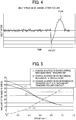
- FIG. 4 is a graph showing fluctuations in the process linear velocity of the intermediate transfer belt 131.
- the intermediate transfer belt 131 travels at a constant process linear velocity within a certain range around a preset process linear velocity.
- the impact thus produced and load on the torque cause the process linear velocity of the intermediate transfer belt 131 to slow down such as shown at the valley portion of the graph in FIG. 4 .
- the recording medium P no longer causes the load on the torque. Therefore, the process linear velocity of the intermediate transfer belt 131 gets accelerated such as shown at the peak portion of the graph in FIG. 4 . If the impact on the secondary transfer nip N is large when the recording medium P enters the secondary transfer nip N, the deceleration ratio of the intermediate transfer belt 131 becomes large, and hence the dip of the valley portion in the graph in FIG. 4 becomes large. As a result, undesirable streaking (horizontal streaking) or a so-called shock jitter appears in halftone images.
- FIG. 5 is a graph showing relations between a space between the intermediate transfer belt 131 and the secondary transfer roller 135, and changes in the process linear velocity of the intermediate transfer belt 131.
- (1) represents changes in the process linear velocity when the recording medium P enters the secondary transfer nip N.
- (2) represents changes in the process linear velocity when the recording medium P exits the secondary transfer nip N.
- (3) represents changes in the process linear velocity when the intermediate transfer belt 131 and the secondary transfer roller 135 that are separated come in contact each other.
- the vertical axis of the graph represents an amount of change in the process linear velocity of the intermediate transfer belt 131, and shows the absolute value at its maximum indicating how much the speed has changed from an average process linear velocity.
- the horizontal axis of the graph represents an amount of space between the intermediate transfer belt 131 and the secondary transfer roller 135 when the intermediate transfer belt 131 and the secondary transfer roller 135 are separated from each other.
- the larger is the space the greater is the impact generated when the intermediate transfer belt 131 and the secondary transfer roller 135 that are separated come in contact with each other again. Therefore, the larger is the space, the larger is the amount by which the process linear velocity changes when the intermediate transfer belt 131 and the secondary transfer roller 135 that are separated come in contact again.
- the intermediate transfer belt 131 and the secondary transfer roller 135 are spaced apart such that the sum of the amount of change in the process linear velocity when the recording medium P enters the secondary transfer nip N and the amount of change in the process linear velocity when the intermediate transfer belt 131 and the secondary transfer roller 135 that are separated come in contact with each other is the smallest.
- changes in the process linear velocity can be minimized when the recording medium P enters the secondary transfer nip N, hence reducing the shock jitter.
- the space between the intermediate transfer belt 131 and the secondary transfer roller 135 that can minimize the changes in the process linear velocity when the recording medium P enters the secondary transfer nip N is referred to as a width W2.
- the intermediate transfer belt 131 and the secondary transfer roller 135 separate from each other, but the impact thus produced is insignificant and does not influence the quality of an output image.
- the space is set to be as large as possible when the recording medium P exits the secondary transfer nip N.
- changes in the process linear velocity can be minimized when the recording medium P exits the secondary transfer nip N, hence reducing the shock jitter,
- the space between the intermediate transfer belt 131 and the secondary transfer roller 135 that can minimize the changes in the process linear velocity when the recording medium P exits the secondary transfer nip N is referred to as a width W1.
- the space when the recording medium P enters the secondary transfer nip N, the space has the width W2.
- the space When the recording medium P exits the secondary transfer nip N, the space has the width W1. This configuration minimizes or prevents the shock jitter, hence achieving good imaging quality.
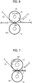
- FIG. 8 is a schematic diagram illustrating the intermediate transfer belt 131 and the secondary transfer roller 135 spaced apart at the width W1.
- FIG. 7 is a schematic diagram illustrating the intermediate transfer belt 131 and the secondary transfer roller 135 contacting each other.
- FIG. 6 is a schematic diagram illustrating the intermediate transfer belt 131 and the secondary transfer roller 135 spaced apart at the width W2.
- FIG. 6 illustrates the eccentric cam 31 immediately before the recording medium P enters the secondary transfer nip N.
- FIG. 7 illustrates the eccentric cam 31 during the transfer process in which the toner image is transferred from the intermediate transfer belt 131 onto the recording medium P.
- FIG. 8 illustrates the eccentric cam 31 just as the recording medium P exits the secondary transfer nip N.
- a cam position A there are three stop positions for the eccentric cam 31, that is, a cam position A, a cam position B, and a cam position C, at which the eccentric cam 31 stops.
- a cam position A when the eccentric cam 31 stops at the cam position A, the intermediate transfer belt 131 and the secondary transfer roller 135 are spaced apart at the width W1.
- the intermediate transfer belt 131 and the secondary transfer roller 135 are in contact with each other.
- the spring 37 applies a necessary transfer pressure to the secondary transfer roller 135 to transfer the toner image from the intermediate transfer belt 131 onto the recording medium P.
- the eccentric cam 31 is rotated about the cam shaft 31a by a rotary driving force transmitted from the stepping motor 33 controlled by the controller 200, thereby enabling the eccentric cam 31 to stop at different positions consecutively in the order of the cam position C, the cam position B, the cam position A, and the cam position C.
- the eccentric cam 31 has such a shape that allows the eccentric cam 31 to change its positions in the order of the cam position C, the cam position A, the cam position B, the cam position C, the cam position A, and the cam position B while making one rotation.
- the controller 200 controls the stepping motor 33 to stop the eccentric cam 31 to stop at the cam position C as illustrated in FIG. 6 . Accordingly, the intermediate transfer belt 131 and the secondary transfer roller 135 are spaced apart at the width W2, letting the recording medium P to enter the secondary transfer nip N.
- the eccentric cam 31 is moved from the cam position C to the cam position B while the margin of the recording medium P passes through the secondary transfer nip N so that the intermediate transfer belt 131 and the secondary transfer roller 135 to come in contact with each other.
- the intermediate transfer belt 131 and the secondary transfer roller 135 are spaced apart at the width W2 such that the sum of the impact when the recording medium P enters the secondary transfer nip N and the impact when the intermediate transfer belt 131 and the secondary transfer roller 135 that are separated come in contact with each other is the smallest, With this configuration, the shock jitter is minimized when the recording medium P enters the secondary transfer nip N.
- the eccentric cam 31 is stopped at the cam position B, and the recording medium P is interposed between the intermediate transfer belt 131 and the secondary transfer roller 135. Accordingly, an adequate transfer pressure can be applied to transfer the toner image from the intermediate transfer belt 131 to the recording medium P.
- the controller 200 controls the stepping motor 33 to move the eccentric cam 31 from the cam position B to the cam position A.
- the eccentric cam 31 is stopped at the cam position A as illustrated in FIG. 8 , thereby separating the intermediate transfer belt 131 and the secondary transfer roller 135 at the width W1 in preparation for the trailing edge of the recording medium P to exit the secondary transfer nip.
- the intermediate transfer belt 131 and the secondary transfer roller 135 are spaced apart at the width W1 when the trailing edge of the recording medium P exits the secondary transfer nip N, thereby minimizing the impact when the trailing edge of the recording medium P exits the secondary transfer nip N. With this configuration, the shock jitter is minimized when the recording medium P exits the secondary transfer nip N.
- the controller 200 controls the stepping motor 33 to move the eccentric cam 31 from the cam position A to the cam position C.
- the toner image is transferred onto the successive recording medium P (the second sheet of the recording medium P) while the intermediate transfer belt 131 and the secondary transfer roller 135 are spaced apart at such a distance that the impact is minimized when the successive recording medium P (the second sheet of the recording medium P) enters the secondary transfer nip N.
- the eccentric cam 31 is rotated as described above when the toner image is transferred from the intermediate transfer belt 131 onto the recording medium P.
- Rotation control of the eccentric cam 31 as described with reference to FIGS, 6 through 8 is most effective, that is, the shock jitter can improve most effectively when the recording medium P is relatively thin and the impact caused by the intermediate transfer belt 131 and the secondary transfer roller 135 contacting each other is significant.
- the impact caused by the recording medium P entering the secondary transfer nip N is more significant than the impact caused by the intermediate transfer belt 131 and the secondary transfer roller 135 coming into contact with each other.
- the intermediate transfer belt 131 and the secondary transfer roller 135 are spaced apart at the width W1, thereby widening the space therebetween.
- the controller 200 causes the stepping motor 33 to stop the eccentric cam 31 at the cam position A to make the space between the intermediate transfer belt 131 and the secondary transfer roller 135 to have the width W1. Then, the recording medium P is introduced to the secondary transfer nip N.
- the controller 200 After the recording medium P enters the secondary transfer nip N, the controller 200 causes the stepping motor 33 to move the eccentric cam 31 from the cam position A to the cam position B while the margin of the recording medium P passes through the secondary transfer nip N, and the eccentric cam 31 is stopped at the cam position B.
- the recording medium P is interposed between the intermediate transfer belt 131 and the secondary transfer roller 135.
- the controller 200 causes the stepping motor 33 to move the eccentric cam 31 from the cam position B to the cam position A.
- the eccentric cam 31 is stopped at the cam position A, thereby making the space to have the width W1.
- the eccentric cam 31 is rotated based on relations between the thickness of the recording medium P and a threshold associated with different thicknesses of the recording medium P.
- the thickness (thickness T A ) of the recording medium P is smaller than a threshold Q A , the impact caused by the recording medium P entering the secondary transfer nip N and the impact caused by the recording medium P exiting the secondary transfer nip N are insignificant. Therefore, when the recording medium P enters the secondary transfer nip N and when the recording medium P exits the secondary transfer nip N, the intermediate transfer belt 131 and the secondary transfer roller 135 are not separated from each other.
- the impact caused by the intermediate transfer belt 131 and the secondary transfer roller 135 coming in contact with each other after being separated is greater than the impact caused by the recording medium P entering the secondary transfer nip N. Therefore, when the recording medium P enters the secondary transfer nip N, the space is reduced so as to reduce the subsequent impact caused by the intermediate transfer belt 131 and the secondary transfer roller 135 coming in contact with each other.
- the impact caused by the recording medium P exiting the secondary transfer nip N is greater than the impact caused by the intermediate transfer belt 131 and the secondary transfer roller 135 separating from each other.
- the width of the space is increased when the recording medium P exits the secondary transfer nip N, thereby reducing the impact when the recording medium P exits the secondary transfer nip N.
- the impact caused by the recording medium P entering the secondary transfer nip N is greater than the impact caused by the intermediate transfer belt 131 and the secondary transfer roller 135 coming in contact with each other after being separated.
- the size of the space is increased when the recording medium P enters the secondary transfer nip N, thereby reducing the impact when the recording medium P enters the secondary transfer nip N.
- the impact caused by the recording medium P exiting the secondary transfer nip N is greater than the impact caused by the intermediate transfer belt 131 and the secondary transfer roller 135 coming in contact with each other after being separated.
- the width of the space is increased when the recording medium P exits the secondary transfer nip N, thereby reducing the impact when the recording medium P exits the secondary transfer nip N.
- rotation of the eccentric cam 31 is adjusted at three different positions in accordance with the thickness of the recording medium P to reduce the shock jitter irrespective of the thickness of the recording medium P. Accordingly, good imaging quality is achieved.
- the image forming apparatus 1 includes the thickness detector 160 on the paper delivery path 123 from the paper feed unit 12 to the secondary transfer nip N.
- the thickness detector 160 serves as a paper thickness detector to detect the thickness of the recording medium P.
- the controller 200 determines the size of the space between the intermediate transfer belt 131 and the secondary transfer roller 135 when the recording medium P enters the secondary transfer nip N and when the recording medium P exits the secondary transfer nip N, and controls the contact-and-separation device 30.
- the thickness detector 160 is a through-beam type optical detector including a light emitting element 161 and a light receiving element 162 disposed opposite the light emitting element 161 via the paper delivery path 123.
- the light receiving element 162 receives light irradiated by the light emitting element 161 and penetrating through the recording medium P.
- a signal corresponding to the intensity of the received light is output as information associated with the thickness of the recording medium P to the controller 200.
- the thickness detector is not limited to a through-beam type optical detector. Any other suitable detector that can detect the thickness of the recording medium P can be used.
- the operation panel 170 (shown in FIG. 3 ) of the image forming apparatus 1 may function as an input device through which users can input information on the thickness of the recording medium P. Based on the input information provided by the users using the operation panel 170, the controller 200 determines the width of the space between the intermediate transfer belt 131 and the secondary transfer roller 135 when the recording medium P enters the secondary transfer nip N and when the recording medium P exits the secondary transfer nip N, and controls the contact-and-separation device 30.
- Table 1 shows relations of a thickness group, a paper thickness (basis weight), and a size of the space (SPACE 1) when the recording medium P enters the secondary transfer nip N and a size of the space (SPACE 2) when the recording medium P exits the secondary transfer nip N.
- THICKNESS GROUP ⁇ ⁇ ⁇ Z THICKNESS (gsm) 0 ⁇ 90 91 ⁇ 157 158 ⁇ 220 221 ⁇ 400 SPACE 1 NONE SMALL SMALL LARGE SPACE 2 NONE SMALL LARGE LARGE
- a thickness group ⁇ is a recording medium P having a basis weight in a range from 0 gsm to 90.0 gsm.
- the recording medium P in the thickness group ⁇ is very thin and produces very small impact when the recording medium P enters the secondary transfer nip N and when the recording medium P exits the secondary transfer nip N.
- the impact that is produced when the intermediate transfer belt 131 and the secondary transfer roller 135 come in contact with each other and when the intermediate transfer belt 131 and the secondary transfer roller 135 separate from each other is translated into the shock jitter. Therefore, when using the recording medium P belonging to the thickness group ⁇ for printing, the intermediate transfer belt 131 and the secondary transfer roller 135 are not moved to contact and separate from each other when the recording medium P enters the secondary transfer nip N and when the recording medium P exits the secondary transfer nip N.
- a thickness group ⁇ is a recording medium P having a basis weight in a range from 90.1 gsm to 157.0 gsm.
- the recording medium P in the thickness group ⁇ is relatively thin and produces small impact when the recording medium P enters the secondary transfer nip N and when the recording medium P exits the secondary transfer nip N. Although the impact is small, the impact is greater than the impact produced by the recording medium P in the thickness group ⁇ . Therefore, when using the recording medium P in the thickness group ⁇ for printing, the intermediate transfer belt 131 and the secondary transfer roller 135 are slightly separated from each other when the recording medium P enters the secondary transfer nip N and when the recording medium P exits the secondary transfer nip N, thereby reducing the impact.
- the recording medium P in the thickness group ⁇ is also thin, the impact that is produced when the intermediate transfer belt 131 and the secondary transfer roller 135 come in contact with each other and when the intermediate transfer belt 131 and the secondary transfer roller 135 separate from each other is translated into the shock jitter. Consequently, the intermediate transfer belt 131 and the secondary transfer roller 135 are not separated by a large amount.
- a thickness group ⁇ is a recording medium P having a basis weight in a range from 157.1 gsm to 220.0 gsm.
- the recording medium P in the thickness group ⁇ is relatively thick and produces greater impact than the recording medium P in the thickness group ⁇ when the recording medium P enters the secondary transfer nip N and when the recording medium P exits the secondary transfer nip N. Therefore, when using the recording medium P in the thickness group ⁇ for printing, the intermediate transfer belt 131 and the secondary transfer roller 135 are separated from each other when the recording medium P enters the secondary transfer nip N and when the recording medium P exits the secondary transfer nip N, thereby reducing the impact,
- the impact that is produced when the intermediate transfer belt 131 and the secondary transfer roller 135 come in contact with each other and when the intermediate transfer belt 131 and the secondary transfer roller 135 separate from each other is translated into the shock jitter. For this reason, the width of the space is relatively small when the recording medium P enters the secondary transfer nip N.
- the impact caused by the intermediate transfer belt 131 and the secondary transfer roller 135 separating from each other is smaller than the impact caused by the recording medium P exiting the secondary transfer nip N. Therefore, when using the recording medium P in the thickness group ⁇ for printing, the intermediate transfer belt 131 and the secondary transfer roller 135 are separated from each other by a large amount when the recording medium P exits the secondary transfer nip N.
- a thickness group Z is a recording medium P having a basis weight in a range from 220.1 gsm to 400.0 gsm.
- the recording medium P in the thickness group Z is very thick and produces significant impact when the recording medium P enters the secondary transfer nip N and when the recording medium P exits the secondary transfer nip N. Therefore, when using the recording medium P in the thickness group Z for printing, the intermediate transfer belt 131 and the secondary transfer roller 135 are separated from each other by a large amount when the recording medium P enters the secondary transfer nip N as well as when the recording medium P exits the secondary transfer nip N.
- FIG. 9 is a diagram for explaining the shape of the eccentric cam 31 and the cam diagram of the eccentric cam 31.
- the distance between the intermediate transfer belt 131 and the secondary transfer roller 135 is zero (0).
- the eccentric cam 31 has three different cam positions: the cam position A, the cam position B, and the cam position C.
- the eccentric cam 31 is rotated about the cam shaft 31a by the rotary driving force transmitted from the stepping motor 33 (shown in FIG. 2 ) controlled by the controller 200, thereby enabling the eccentric cam 31 to stop at different cam positions.
- the eccentric cam 31 When the eccentric cam 31 is at the cam position A, the eccentric cam 31 pushes down the ball bearing 32 disposed coaxially on the same shaft as the secondary transfer roller 135, thereby making the distance between the intermediate transfer belt 131 and the secondary transfer roller 135 approximately 0.6 mm. Accordingly, the intermediate transfer belt 131 and the secondary transfer roller 135 are separated completely.
- the eccentric cam 31 When the eccentric cam 31 is at the cam position B, the eccentric cam 31 is separated from the ball bearing 32 completely, and the intermediate transfer belt 131 and the secondary transfer roller 135 are in contact with each other completely. Accordingly, an adequate transfer pressure can be applied during the transfer process, thereby obtaining good imaging quality.
- the eccentric cam 31 when the eccentric cam 31 is at the cam position B, the secondary transfer roller 135 is pressed against the secondary-transfer opposed roller 136 via the intermediate transfer belt 131, and the elastic layer of the secondary transfer roller 135 is squashed or deformed elastically. Therefore, when the eccentric cam 31 is at the cam position B, the distance between the intermediate transfer belt 131 and the secondary transfer roller 135 has a negative value in accordance with deformation of the elastic layer of the secondary transfer roller 135.
- the eccentric cam 31 When the eccentric cam 31 is at the cam position C, the eccentric cam 31 pushes down slightly the ball bearing 32, thereby making the distance between the intermediate transfer belt 131 and the secondary transfer roller 135 approximately 0.1 mm.
- the intermediate transfer belt 131 and the secondary transfer roller 135 may contact each other slightly so that the transfer pressure is reduced.
- the desired distance between the intermediate transfer belt 131 and the secondary transfer roller 135 can be achieved.
- Table 2 shows relations of the thickness group and the cam position of the eccentric cam 31 at different timing, i.e., when the recording medium P enters the secondary transfer nip N, during the transfer process, and when the recording medium P exits the secondary transfer nip N.
- the thickness groups i.e., the thickness groups ⁇ , ⁇ , ⁇ , and Z, and the space between the intermediate transfer belt 131 and the secondary transfer roller 135 by rotating the eccentric cam 31 such as shown in Table 1, it is necessary to situate the eccentric cam 31 at the respective cam positions shown in Table 2, at times i.e., when the recording medium P enters the secondary transfer nip N, during the transfer process, and when the recording medium exits the secondary transfer nip N.
- the eccentric cam 31 is moved to the cam position A. During the transfer process, it is necessary to move the eccentric cam 31 to the cam position B. When the recording medium P exits the secondary transfer nip N, it is necessary to move the eccentric cam 31 back to the cam position A.
- the eccentric cam 31 stands by at the cam position A.
- the cam position of the eccentric cam 31 when the preceding recording medium P exits the secondary transfer nip N coincides with the cam position of the eccentric cam 31 when the successive recording medium P enters the secondary transfer nip N.
- the cam position of the eccentric cam 31 when the preceding recording medium P exits the secondary transfer nip N coincides with the cam position of the eccentric cam 31 when the successive recording medium P enters the secondary transfer nip N. Accordingly, even when the sheet interval between the preceding recording medium P and the successive recording medium P is relatively short, the subsequent operation can be carried out without delay.
- the cam position of the eccentric cam 31 is changed from the cam position B during the transfer process to the cam position C when the recording medium P exits the secondary transfer nip N in the following manner.
- the eccentric cam 31 shown in FIG. 7 during the transfer process is rotated in the clockwise direction to change the cam position from the cam position B to the cam position C.
- the eccentric cam 31 is positioned at the cam position C.
- the cam position of the eccentric cam 31 is changed from the cam position B during the transfer process to the cam position C when the recording medium P exits the secondary transfer nip N in the following manner.
- the eccentric cam 31 shown in FIG. 7 during the transfer process is rotated in the counterclockwise direction to change the cam position from the cam position B to the cam position A and to the cam position C.
- the eccentric cam 31 is positioned at the cam position C.
- the size of the space between the intermediate transfer belt 131 and the secondary transfer roller 135 is changed from the large space to the small space in a shorter period of time, as compared with stopping the eccentric cam 31 temporarily at the cam position A, and then moving the eccentric cam 31 to the cam position C.
- the intermediate transfer belt and the secondary transfer roller are spaced apart a certain distance in accordance with a thickness of the recording medium such that the impact is reduced as much as possible when the intermediate transfer belt and the secondary transfer roller come in contact with each other and the transfer pressure is zero when the recording medium enters and exits the secondary transfer nip.
- the impact is reduced when the intermediate transfer belt and the secondary transfer roller come in contact with each other and hence shock jitter is reduced without separating the intermediate transfer belt and the secondary transfer roller in accordance with the thickness of the recording medium more than necessary.
- the recording media When performing continuous printing in which images are formed on a plurality of recording media, the recording media generally have the same thickness, but there may be a case in which recording media with different thicknesses may be used during continuous printing.
- the thickness of a successive sheet is different from the thickness of a preceding sheet, after the preceding sheet exits the secondary transfer nip but during a time in which a sheet interval area, i.e., an area between the preceding sheet and the successive sheet, passes through the secondary transfer nip, the space between the intermediate transfer belt and the secondary transfer roller is changed in accordance with the thickness of the successive sheet.
- the interval between the preceding sheet and the successive sheet is significantly short.
- the contact-and-separation device cannot change the size of the space between the intermediate transfer belt and the secondary transfer roller in accordance with the thickness of the successive sheet while the sheet interval area between the preceding sheet and the successive sheet passes through the secondary transfer nip. That is, the space between the intermediate transfer belt and the secondary transfer roller cannot be changed before the successive sheet enters the secondary transfer nip.
- the sheet interval area between the preceding sheet and the successive sheet may be increased so that the contact-and-separation device can change the space between the intermediate transfer belt and the secondary transfer nip before the successive sheet enters the secondary transfer nip.
- a wider sheet interval area between the preceding sheet and the successive sheet decreases productivity in the continuous printing
- the recording media When performing continuous printing in which images are formed on a plurality of recording media, the recording media generally have the same thickness, but there may be a case in which recording media with different thicknesses may be used during continuous printing.
- the cam position of the eccentric cam 31 when the preceding recording medium P exits the secondary transfer nip N differs from the cam position of the eccentric cam 31 when the successive recording medium P enters the secondary transfer nip N.
- the cam position of the eccentric cam 31 when the preceding recording medium P exits the secondary transfer nip N may be changed to the cam position of the eccentric cam 31 for the successive recording medium P before the successive recording medium P enters the secondary transfer nip N.
- the cam position cannot be changed while the sheet interval area passes through the secondary transfer nip N.
- the cam position of the eccentric cam 31 for the preceding recording medium P (first sheet) of the thickness group ⁇ is at the cam position B when the recording medium P (first sheet) enters the secondary transfer nip N.
- the eccentric cam 31 is at the cam position B.
- the eccentric cam 31 is at the cam position B .
- the speed at which the sheet interval area between the preceding recording medium P and the successive recording medium P passes through the secondary transfer nip N is so fast that the cam position of the eccentric cam 31 cannot be changed from the cam position B to the cam position C without delay.
- the sheet interval between the preceding recording medium P and the successive recording medium P may be increased when printing out recording media of different thickness groups, but the printing productivity decreases.
- the size of the space between the intermediate transfer belt 131 and the secondary transfer roller 135 when the preceding recording medium P exits the secondary transfer nip N corresponds to the size of the space associated with the thickness group to which the successive recording medium P belongs when the successive recording medium P enters the secondary transfer nip N.
- the cam position of the eccentric cam 31 when the preceding recording medium P exits the secondary transfer nip N can be changed reliably to the cam position of the eccentric cam 31 for the successive recording medium P before the successive recording medium P enters the secondary transfer nip N.
- the cam position of the eccentric cam 31 is changed while the sheet interval area between the preceding recording medium P and the successive recording medium P passes through the secondary transfer nip N.
- This configuration does not require extension of the sheet interval area when printing out consecutively recording media P of different thickness groups, hence preventing degradation of the productivity.
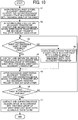
- FIG. 11 is a table showing relations of the thickness groups and the cam positions of the eccentric cam 31 at times, i.e., when the recording medium P enters the secondary transfer nip N, during the transfer process, and when the recording medium P exits the secondary transfer nip N in the event in which the recording media P belonging to different thickness groups are printed out consecutively.
- the first row lists the thickness groups of the successive recording medium P.
- the left column lists the thickness groups of the preceding recording medium P.
- the eccentric cam 31 is positioned at the cam position C when the preceding recording medium P (first sheet) enters the secondary transfer nip N. During the transfer process, the eccentric cam 31 is positioned at the cam position B. When the recording medium P exits the secondary transfer nip N, the eccentric cam 31 is positioned at the cam position B.
- the eccentric cam 31 is situated at the cam position C as shown in Table 2.
- the eccentric cam 31 is situated at the cam position B when the successive recording medium P enters the secondary transfer nip N as shown in Table 2.
- the cam position of the eccentric cam 31 is changed to the cam position B.
- the cam position of the eccentric cam 31 when the preceding recording medium P exits the secondary transfer nip N coincides with the cam position of the eccentric cam 31 when the successive recording medium P enters the secondary transfer nip N. That is, the eccentric cam 31 is situated at the cam position B when the preceding recording medium P exits the secondary transfer nip N as well as when the successive recording medium P enters the secondary transfer nip N.
- This configuration does not need to change the space between the intermediate transfer belt 131 and the secondary transfer roller 135 while the sheet interval area passes through the secondary transfer nip N, thereby enabling consecutive printing using recording media with different thicknesses in the high-speed image forming apparatus without degrading the productivity.
- the size of the space when the preceding recording medium P passes through the secondary transfer nip N is changed to the size of the space corresponding to the thickness group of the successive recording medium P when the successive recording medium P enters the secondary transfer nip N.
- the eccentric cam 31 When printing out consecutively recording media belonging to different thickness groups, the eccentric cam 31 is rotated as described above, thereby reducing the shock jitter without degrading the productivity even when the sheet interval is very short such as in the high-speed image forming apparatus.
- the reason for changing the space when the preceding recording medium P exits the secondary transfer nip N in accordance with the thickness group of the successive recording medium P is that the factor that promotes the shock jitter is less when the recording medium P exits the secondary transfer nip N than when the recording medium P enters the secondary transfer nip N.
- the space between the intermediate transfer belt 131 and the secondary transfer roller 135 is set such that the relations between the space when the successive recording medium P enters the secondary transfer nip N and the thickness group (thickness) of the successive recording medium P are always ensured.
- This configuration can reduce the shock jitter more effectively as compared with setting the space to maintain the relations between the space when the preceding recording medium P exits the secondary transfer nip N and the thickness group of the preceding recording medium P.
- the space when the successive recording medium P (second sheet) enters the secondary transfer nip N may be set in accordance with the thickness group of the preceding recording medium P (first sheet).
- This configuration also enables consecutive printing of recording media P that belong to different thickness groups without degrading the productivity. In this case, the relations between the space when the preceding recording medium P exits the secondary transfer nip N and the thickness group (thickness) are always ensured.
- this configuration prevents more reliably the image density near the trailing edge of the preceding recording medium P from changing, as compared with the configuration that ensures the relations between the space when the successive recording medium P enters the secondary transfer nip N and the thickness group (thickness).
- a good printing result can be expected if more emphasis is given to the image near the trailing edge of the recording medium P than the image near the leading edge of the recording medium P.
- FIG. 10 is a flowchart showing steps of control of movement of the intermediate transfer belt 131 and the secondary transfer roller 135 during continuous printing according to illustrative embodiment of the present disclosure.
- the thickness group of the recording medium P is specified based on the detection result provided by the thickness detector 160 and input by users using the operation panel 170
- the controller 200 controls the contact-and-separation device 30.
- the space between the intermediate transfer belt 131 and the secondary transfer roller 135 when the preceding recording medium P (the first sheet) enters the secondary transfer nip N is formed in accordance with the thickness group of the preceding recording medium P by the contact-and-separation device 30 at step S1.
- the contact-and-separation device 30 moves the intermediate transfer belt 131 and the secondary transfer roller 135 to contact each other.
- the intermediate transfer belt 131 and the secondary transfer roller 135 are not separated, that is, they are in contact with each other when the preceding recording medium P enters the secondary transfer nip N, the intermediate transfer belt 131 and the secondary transfer roller 135 remain in contact with each other.
- step S3 whether or not the thickness group of the successive recording medium P (the second sheet) coincides with the thickness group of the preceding recording medium P (first sheet) is determined. If the thickness group of the successive recording medium P (the second sheet) is the same as the thickness group of the preceding recording medium P (Yes at S3), the space when the preceding recording medium P exits the secondary transfer nip N is formed in accordance with the thickness group of the preceding recording medium P by the contact-and-separation device 30 at step S4.
- the space when the preceding recording medium P exits the secondary transfer nip N is formed in accordance with the thickness group of the successive recording medium P by the contact-and-separation device 30 at step S8.
- step S5 after the successive recording medium P enters the secondary transfer nip N, the contact-and-separation device 30 moves the intermediate transfer belt 131 and the secondary transfer roller 135 to contact each other. Then, at step S6, whether or not the recording medium P in the secondary transfer nip N is the last sheet of the recording medium P in the continuous printing is determined.
- the recording medium P in the secondary transfer nip N is not the last sheet in the continuous printing (No at S6), the recording medium P in the secondary transfer nip N (the second sheet) is now treated as the preceding recording medium P, and the subsequent recording medium P (the third sheet) delivered to the secondary transfer nip N is treated as the successive recording medium P. Accordingly, the above-described series of control is performed repeatedly as needed.
- the recording medium P in the secondary transfer nip N is the last sheet in the continuous printing (Yes at S6), the space when the last sheet of the recording medium P exits the secondary transfer nip N is formed in accordance with the thickness group of this last sheet by the contact-and-separation device 30 at step S7, and the contact-and-separation control in the continuous printing is ended.
- An image forming apparatus includes an image bearer such as the intermediate transfer belt 131 to bear a toner image on a surface of the image bearer, a nip forming device such as the secondary transfer roller 135 to contact the image bearer to form a transfer nip such as the secondary transfer nip N between the nip forming device and the image bearer and interpose a recording medium therebetween to transfer the toner image from the image bearer onto the recording medium in the transfer nip, a contact-and-separation device such as the contact-and-separation device 30 to move the image bearer and the nip forming device to contact and separate from each other, a thickness information retrieving device such as the thickness detector 160 to obtain information on a thickness of the recording medium, a controller such as the controller 200 to control the contact-and-separation device based on the information on the thickness of the recording medium such that in a case in which a thickness of a preceding recording medium and a thickness of a successive
- the size of the space when the preceding recording medium exits the transfer nip is adjusted to the size corresponding to the thickness of the successive recording medium when the successive recording medium enters the transfer nip.
- the space can be adjusted to the size corresponding to the thickness of the successive recording medium when the successive recording medium enters the transfer nip.
- the image forming apparatus includes a support roller such as the secondary-transfer opposed roller 136 including a rotary shaft disposed opposite to the nip forming device via the image bearer to rotatably support the image bearer to form the transfer nip.
- the nip forming device is a roller rotatable about a rotary shaft, and the image bearer is a belt.
- the contact-and-separation device includes a contact device such as the ball bearing 32 disposed on one of the rotary shaft of the support roller and the rotary shaft of the nip forming device, an eccentric cam such as the eccentric cam 31 disposed on the other of the rotary shaft of the support roller and the rotary shaft of the nip forming device, a cam controller such as the stepping motor 33 to rotate the eccentric cam to at least three different positions to change the size of the space between the image bearer and the nip forming device, and a biasing device such as the spring 37 to bias the contact device in a direction in which the support roller and the nip forming device contact each other.
- a contact device such as the ball bearing 32 disposed on one of the rotary shaft of the support roller and the rotary shaft of the nip forming device
- an eccentric cam such as the eccentric cam 31 disposed on the other of the rotary shaft of the support roller and the rotary shaft of the nip forming device
- a cam controller such
- the cam controller rotates the eccentric cam to contact and move the contact device in a direction in which the image bearer and the nip forming device are separated from each other against a pressure from the biasing device, to form the space between the image bearer and the nip forming device.
- the cam controller rotates the eccentric cam to separate from the contact device while facing the contact device and move the contact device in a direction in which the image bearer and the nip forming device approach each other such that the support roller and the nip forming device contact each other via the image bearer with the pressure from the biasing device to form the transfer nip.
- the controller controls the contact-and-separation device based on the information on the thickness obtained by the thickness information retrieving device to adjust the space between the image bearer and the nip forming device when the preceding recording medium enters the transfer nip and when the successive recording medium exits the transfer nip, to a preset size corresponding to the recording medium.
- the thickness information retrieving device is a thickness detector such as the thickness detector 160 that detects a thickness of the recording medium on a paper delivery path such as the paper delivery path 123.
- the thickness of the recording medium can be detected automatically upon continuous printing, and the size of the space is set accordingly.
- the thickness information retrieving device includes an input device such as the operation panel 170 through which users input information on the thickness of the recording medium P.
- the space is set based on the information input by the users.
- the present invention is employed in the image forming apparatus.
- the image forming apparatus includes, but is not limited to, an electrophotographic image forming apparatus, a copier, a printer, a facsimile machine, and a multi-functional system.
Landscapes
- Physics & Mathematics (AREA)
- General Physics & Mathematics (AREA)
- Electrostatic Charge, Transfer And Separation In Electrography (AREA)
- Control Or Security For Electrophotography (AREA)
Applications Claiming Priority (1)
| Application Number | Priority Date | Filing Date | Title |
|---|---|---|---|
| JP2014109287A JP6260868B2 (ja) | 2014-05-27 | 2014-05-27 | 画像形成装置 |
Publications (2)
| Publication Number | Publication Date |
|---|---|
| EP2950155A1 EP2950155A1 (en) | 2015-12-02 |
| EP2950155B1 true EP2950155B1 (en) | 2019-10-02 |
Family
ID=53177283
Family Applications (1)
| Application Number | Title | Priority Date | Filing Date |
|---|---|---|---|
| EP15168004.8A Active EP2950155B1 (en) | 2014-05-27 | 2015-05-18 | Image forming apparatus |
Country Status (3)
| Country | Link |
|---|---|
| US (1) | US9519245B2 (enExample) |
| EP (1) | EP2950155B1 (enExample) |
| JP (1) | JP6260868B2 (enExample) |
Families Citing this family (16)
| Publication number | Priority date | Publication date | Assignee | Title |
|---|---|---|---|---|
| US9547249B2 (en) * | 2014-09-26 | 2017-01-17 | Ricoh Company, Ltd. | Image forming apparatus |
| JP6493802B2 (ja) | 2015-07-07 | 2019-04-03 | 株式会社リコー | 転写装置及び画像形成装置 |
| US9846396B2 (en) | 2015-10-14 | 2017-12-19 | Ricoh Company, Ltd. | Transfer device and image forming apparatus incorporating same |
| EP3258320A1 (en) | 2016-06-17 | 2017-12-20 | Ricoh Company, Ltd. | Image forming apparatus and image forming method |
| JP6872160B2 (ja) | 2016-12-09 | 2021-05-19 | 株式会社リコー | カム駆動装置及び画像形成装置 |
| JP7035463B2 (ja) * | 2017-11-09 | 2022-03-15 | コニカミノルタ株式会社 | 画像形成装置 |
| JP2020034583A (ja) | 2018-08-27 | 2020-03-05 | 株式会社リコー | ベルト寄り検知装置、ベルト装置、画像形成装置、及び、当接部材の製造方法 |
| JP2021140054A (ja) * | 2020-03-06 | 2021-09-16 | 株式会社リコー | 画像形成装置 |
| JP7449487B2 (ja) | 2020-04-28 | 2024-03-14 | 株式会社リコー | 画像形成装置 |
| WO2023008456A1 (ja) * | 2021-07-30 | 2023-02-02 | 株式会社デュプロ | 転写装置 |
| US11754964B2 (en) | 2021-09-21 | 2023-09-12 | Ricoh Company, Ltd. | Cam driver, transfer device, and image forming apparatus |
| JP2024015682A (ja) | 2022-07-25 | 2024-02-06 | 株式会社リコー | 画像形成装置 |
| JP2024061465A (ja) | 2022-10-21 | 2024-05-07 | 株式会社リコー | 加圧装置、及び画像形成装置 |
| JP2024066531A (ja) * | 2022-11-02 | 2024-05-16 | シャープ株式会社 | 画像形成装置 |
| JP2024077399A (ja) | 2022-11-28 | 2024-06-07 | 株式会社リコー | 加圧装置及び画像形成装置 |
| JP2024115253A (ja) | 2023-02-14 | 2024-08-26 | 株式会社リコー | 転写装置及び画像形成装置 |
Family Cites Families (31)
| Publication number | Priority date | Publication date | Assignee | Title |
|---|---|---|---|---|
| JP2007139915A (ja) | 2005-11-15 | 2007-06-07 | Ricoh Co Ltd | 画像形成装置 |
| JP4759433B2 (ja) | 2006-04-18 | 2011-08-31 | 株式会社リコー | 画像形成装置 |
| US7869752B2 (en) | 2007-06-23 | 2011-01-11 | Ricoh Company Limited | Cleaning device, fixing device, and image forming apparatus |
| JP5181553B2 (ja) | 2007-07-09 | 2013-04-10 | 株式会社リコー | 転写定着装置及び画像形成装置 |
| JP2009115956A (ja) | 2007-11-05 | 2009-05-28 | Ricoh Co Ltd | 転写定着装置、及び画像形成装置 |
| US8422037B2 (en) | 2008-02-19 | 2013-04-16 | Ricoh Company, Ltd. | Image forming apparatus |
| JP5233455B2 (ja) | 2008-07-09 | 2013-07-10 | 株式会社リコー | 転写定着装置及び画像形成装置 |
| JP5200722B2 (ja) | 2008-07-17 | 2013-06-05 | 株式会社リコー | 画像記録装置 |
| JP2010134125A (ja) | 2008-12-03 | 2010-06-17 | Ricoh Co Ltd | 画像形成装置 |
| US8433221B2 (en) | 2008-12-04 | 2013-04-30 | Ricoh Company, Ltd. | Image forming apparatus with transfer nip adjustment function |
| JP5472782B2 (ja) | 2008-12-04 | 2014-04-16 | 株式会社リコー | 画像形成装置 |
| JP5299772B2 (ja) * | 2009-03-02 | 2013-09-25 | 株式会社リコー | 画像形成装置 |
| JP5257848B2 (ja) | 2009-03-10 | 2013-08-07 | 株式会社リコー | 転写定着装置及び画像形成装置 |
| US8422925B2 (en) | 2009-03-17 | 2013-04-16 | Ricoh Company, Ltd. | Transfer-fixing device and image forming apparatus incorporating same |
| JP5392486B2 (ja) | 2009-10-19 | 2014-01-22 | コニカミノルタ株式会社 | 画像形成装置及びその制御方法 |
| JP5375592B2 (ja) | 2009-12-24 | 2013-12-25 | 株式会社リコー | 転写装置及びそれを用いた画像形成装置 |
| JP5540719B2 (ja) * | 2010-01-15 | 2014-07-02 | 株式会社リコー | 画像形成装置 |
| JP5509939B2 (ja) * | 2010-03-08 | 2014-06-04 | 株式会社リコー | 画像形成装置 |
| JP5707787B2 (ja) * | 2010-06-10 | 2015-04-30 | 株式会社リコー | 転写装置及びそれを用いた画像形成装置 |
| US8666270B2 (en) | 2010-06-21 | 2014-03-04 | Ricoh Company, Ltd. | Image forming apparatus |
| JP5915085B2 (ja) | 2010-11-15 | 2016-05-11 | 株式会社リコー | 転写装置及びそれを用いた画像形成装置 |
| JP6148817B2 (ja) | 2011-08-15 | 2017-06-14 | 株式会社リコー | 定着装置および画像形成装置 |
| JP6019965B2 (ja) * | 2012-09-10 | 2016-11-02 | 株式会社リコー | 画像形成装置 |
| JP2014071330A (ja) * | 2012-09-28 | 2014-04-21 | Ricoh Co Ltd | 転写装置及び画像形成装置 |
| JP2014106284A (ja) | 2012-11-26 | 2014-06-09 | Ricoh Co Ltd | 冷却システム、及び画像形成装置 |
| JP6187857B2 (ja) * | 2013-02-14 | 2017-08-30 | 株式会社リコー | 転写装置、及び画像形成装置 |
| US9046853B2 (en) | 2013-03-14 | 2015-06-02 | Ricoh Company, Ltd. | Image forming apparatus |
| EP2821858B1 (en) | 2013-05-01 | 2020-06-03 | Ricoh Company, Ltd. | Image forming apparatus |
| JP6270125B2 (ja) | 2013-08-02 | 2018-01-31 | 株式会社リコー | 画像形成装置 |
| JP2015031890A (ja) | 2013-08-06 | 2015-02-16 | 株式会社リコー | 異常監視システム及び画像形成装置 |
| JP6256793B2 (ja) | 2013-08-13 | 2018-01-10 | 株式会社リコー | 駆動力伝達装置及び画像形成装置 |
-
2014
- 2014-05-27 JP JP2014109287A patent/JP6260868B2/ja active Active
-
2015
- 2015-05-14 US US14/712,307 patent/US9519245B2/en active Active
- 2015-05-18 EP EP15168004.8A patent/EP2950155B1/en active Active
Non-Patent Citations (1)
| Title |
|---|
| None * |
Also Published As
| Publication number | Publication date |
|---|---|
| JP2015225172A (ja) | 2015-12-14 |
| EP2950155A1 (en) | 2015-12-02 |
| US20150346651A1 (en) | 2015-12-03 |
| JP6260868B2 (ja) | 2018-01-17 |
| US9519245B2 (en) | 2016-12-13 |
Similar Documents
| Publication | Publication Date | Title |
|---|---|---|
| EP2950155B1 (en) | Image forming apparatus | |
| US9274461B2 (en) | Transfer device and image forming apparatus incorporating same | |
| US9778603B2 (en) | Transfer device and image forming apparatus incorporating same | |
| US8873982B2 (en) | Image forming apparatus with mechanism capable of moving transfer device with respect to toner image carrier and image forming method for moving transfer device with respect to toner image carrier | |
| EP3026500B1 (en) | Image forming apparatus and method of separating recording medium | |
| US20090190949A1 (en) | Image forming apparatus | |
| US9465331B2 (en) | Image forming apparatus | |
| US20160091816A1 (en) | Image forming apparatus | |
| US9718634B2 (en) | Sheet thickness detector, sheet conveyor incorporating same, and image forming apparatus incorporating same | |
| US11366404B2 (en) | Image forming apparatus and adjusting method | |
| US9348271B2 (en) | Transfer device and image forming apparatus including same | |
| US9316978B2 (en) | Fixing device, image forming apparatus, and fixing method | |
| JP6171552B2 (ja) | 転写装置、及び、画像形成装置 | |
| JP6284025B2 (ja) | 画像形成装置 | |
| US12416894B2 (en) | Image forming apparatus | |
| US10768556B2 (en) | Image forming apparatus | |
| JP4346278B2 (ja) | 画像形成装置 | |
| JP2023085901A (ja) | 画像形成装置 | |
| JP2011118228A (ja) | 画像形成装置 | |
| JP2006251664A (ja) | 画像形成装置 | |
| JP2005257847A (ja) | 画像形成装置 | |
| EP2574988A2 (en) | Image forming apparatus with mechanism capable of moving transfer device with respect to toner image carrier | |
| JP2010217852A (ja) | 画像形成装置 | |
| JP2016109978A (ja) | 画像形成装置 | |
| JP2016080874A (ja) | 画像形成方法及び画像形成装置 |
Legal Events
| Date | Code | Title | Description |
|---|---|---|---|
| 17P | Request for examination filed |
Effective date: 20150518 |
|
| AK | Designated contracting states |
Kind code of ref document: A1 Designated state(s): AL AT BE BG CH CY CZ DE DK EE ES FI FR GB GR HR HU IE IS IT LI LT LU LV MC MK MT NL NO PL PT RO RS SE SI SK SM TR |
|
| AX | Request for extension of the european patent |
Extension state: BA ME |
|
| PUAI | Public reference made under article 153(3) epc to a published international application that has entered the european phase |
Free format text: ORIGINAL CODE: 0009012 |
|
| STAA | Information on the status of an ep patent application or granted ep patent |
Free format text: STATUS: EXAMINATION IS IN PROGRESS |
|
| 17Q | First examination report despatched |
Effective date: 20190228 |
|
| GRAP | Despatch of communication of intention to grant a patent |
Free format text: ORIGINAL CODE: EPIDOSNIGR1 |
|
| STAA | Information on the status of an ep patent application or granted ep patent |
Free format text: STATUS: GRANT OF PATENT IS INTENDED |
|
| INTG | Intention to grant announced |
Effective date: 20190429 |
|
| GRAS | Grant fee paid |
Free format text: ORIGINAL CODE: EPIDOSNIGR3 |
|
| GRAA | (expected) grant |
Free format text: ORIGINAL CODE: 0009210 |
|
| STAA | Information on the status of an ep patent application or granted ep patent |
Free format text: STATUS: THE PATENT HAS BEEN GRANTED |
|
| AK | Designated contracting states |
Kind code of ref document: B1 Designated state(s): AL AT BE BG CH CY CZ DE DK EE ES FI FR GB GR HR HU IE IS IT LI LT LU LV MC MK MT NL NO PL PT RO RS SE SI SK SM TR |
|
| REG | Reference to a national code |
Ref country code: GB Ref legal event code: FG4D |
|
| REG | Reference to a national code |
Ref country code: CH Ref legal event code: EP Ref country code: AT Ref legal event code: REF Ref document number: 1186868 Country of ref document: AT Kind code of ref document: T Effective date: 20191015 |
|
| REG | Reference to a national code |
Ref country code: DE Ref legal event code: R096 Ref document number: 602015038933 Country of ref document: DE |
|
| REG | Reference to a national code |
Ref country code: IE Ref legal event code: FG4D |
|
| REG | Reference to a national code |
Ref country code: NL Ref legal event code: FP |
|
| REG | Reference to a national code |
Ref country code: LT Ref legal event code: MG4D |
|
| REG | Reference to a national code |
Ref country code: AT Ref legal event code: MK05 Ref document number: 1186868 Country of ref document: AT Kind code of ref document: T Effective date: 20191002 |
|
| PG25 | Lapsed in a contracting state [announced via postgrant information from national office to epo] |
Ref country code: PL Free format text: LAPSE BECAUSE OF FAILURE TO SUBMIT A TRANSLATION OF THE DESCRIPTION OR TO PAY THE FEE WITHIN THE PRESCRIBED TIME-LIMIT Effective date: 20191002 Ref country code: LT Free format text: LAPSE BECAUSE OF FAILURE TO SUBMIT A TRANSLATION OF THE DESCRIPTION OR TO PAY THE FEE WITHIN THE PRESCRIBED TIME-LIMIT Effective date: 20191002 Ref country code: GR Free format text: LAPSE BECAUSE OF FAILURE TO SUBMIT A TRANSLATION OF THE DESCRIPTION OR TO PAY THE FEE WITHIN THE PRESCRIBED TIME-LIMIT Effective date: 20200103 Ref country code: ES Free format text: LAPSE BECAUSE OF FAILURE TO SUBMIT A TRANSLATION OF THE DESCRIPTION OR TO PAY THE FEE WITHIN THE PRESCRIBED TIME-LIMIT Effective date: 20191002 Ref country code: AT Free format text: LAPSE BECAUSE OF FAILURE TO SUBMIT A TRANSLATION OF THE DESCRIPTION OR TO PAY THE FEE WITHIN THE PRESCRIBED TIME-LIMIT Effective date: 20191002 Ref country code: FI Free format text: LAPSE BECAUSE OF FAILURE TO SUBMIT A TRANSLATION OF THE DESCRIPTION OR TO PAY THE FEE WITHIN THE PRESCRIBED TIME-LIMIT Effective date: 20191002 Ref country code: PT Free format text: LAPSE BECAUSE OF FAILURE TO SUBMIT A TRANSLATION OF THE DESCRIPTION OR TO PAY THE FEE WITHIN THE PRESCRIBED TIME-LIMIT Effective date: 20200203 Ref country code: BG Free format text: LAPSE BECAUSE OF FAILURE TO SUBMIT A TRANSLATION OF THE DESCRIPTION OR TO PAY THE FEE WITHIN THE PRESCRIBED TIME-LIMIT Effective date: 20200102 Ref country code: NO Free format text: LAPSE BECAUSE OF FAILURE TO SUBMIT A TRANSLATION OF THE DESCRIPTION OR TO PAY THE FEE WITHIN THE PRESCRIBED TIME-LIMIT Effective date: 20200102 Ref country code: SE Free format text: LAPSE BECAUSE OF FAILURE TO SUBMIT A TRANSLATION OF THE DESCRIPTION OR TO PAY THE FEE WITHIN THE PRESCRIBED TIME-LIMIT Effective date: 20191002 Ref country code: LV Free format text: LAPSE BECAUSE OF FAILURE TO SUBMIT A TRANSLATION OF THE DESCRIPTION OR TO PAY THE FEE WITHIN THE PRESCRIBED TIME-LIMIT Effective date: 20191002 |
|
| PG25 | Lapsed in a contracting state [announced via postgrant information from national office to epo] |
Ref country code: IS Free format text: LAPSE BECAUSE OF FAILURE TO SUBMIT A TRANSLATION OF THE DESCRIPTION OR TO PAY THE FEE WITHIN THE PRESCRIBED TIME-LIMIT Effective date: 20200224 Ref country code: HR Free format text: LAPSE BECAUSE OF FAILURE TO SUBMIT A TRANSLATION OF THE DESCRIPTION OR TO PAY THE FEE WITHIN THE PRESCRIBED TIME-LIMIT Effective date: 20191002 Ref country code: RS Free format text: LAPSE BECAUSE OF FAILURE TO SUBMIT A TRANSLATION OF THE DESCRIPTION OR TO PAY THE FEE WITHIN THE PRESCRIBED TIME-LIMIT Effective date: 20191002 Ref country code: CZ Free format text: LAPSE BECAUSE OF FAILURE TO SUBMIT A TRANSLATION OF THE DESCRIPTION OR TO PAY THE FEE WITHIN THE PRESCRIBED TIME-LIMIT Effective date: 20191002 |
|
| PG25 | Lapsed in a contracting state [announced via postgrant information from national office to epo] |
Ref country code: AL Free format text: LAPSE BECAUSE OF FAILURE TO SUBMIT A TRANSLATION OF THE DESCRIPTION OR TO PAY THE FEE WITHIN THE PRESCRIBED TIME-LIMIT Effective date: 20191002 |
|
| REG | Reference to a national code |
Ref country code: DE Ref legal event code: R097 Ref document number: 602015038933 Country of ref document: DE |
|
| PG2D | Information on lapse in contracting state deleted |
Ref country code: IS |
|
| PG25 | Lapsed in a contracting state [announced via postgrant information from national office to epo] |
Ref country code: RO Free format text: LAPSE BECAUSE OF FAILURE TO SUBMIT A TRANSLATION OF THE DESCRIPTION OR TO PAY THE FEE WITHIN THE PRESCRIBED TIME-LIMIT Effective date: 20191002 Ref country code: DK Free format text: LAPSE BECAUSE OF FAILURE TO SUBMIT A TRANSLATION OF THE DESCRIPTION OR TO PAY THE FEE WITHIN THE PRESCRIBED TIME-LIMIT Effective date: 20191002 Ref country code: EE Free format text: LAPSE BECAUSE OF FAILURE TO SUBMIT A TRANSLATION OF THE DESCRIPTION OR TO PAY THE FEE WITHIN THE PRESCRIBED TIME-LIMIT Effective date: 20191002 Ref country code: IS Free format text: LAPSE BECAUSE OF FAILURE TO SUBMIT A TRANSLATION OF THE DESCRIPTION OR TO PAY THE FEE WITHIN THE PRESCRIBED TIME-LIMIT Effective date: 20200202 |
|
| PLBE | No opposition filed within time limit |
Free format text: ORIGINAL CODE: 0009261 |
|
| STAA | Information on the status of an ep patent application or granted ep patent |
Free format text: STATUS: NO OPPOSITION FILED WITHIN TIME LIMIT |
|
| PG25 | Lapsed in a contracting state [announced via postgrant information from national office to epo] |
Ref country code: SK Free format text: LAPSE BECAUSE OF FAILURE TO SUBMIT A TRANSLATION OF THE DESCRIPTION OR TO PAY THE FEE WITHIN THE PRESCRIBED TIME-LIMIT Effective date: 20191002 Ref country code: IT Free format text: LAPSE BECAUSE OF FAILURE TO SUBMIT A TRANSLATION OF THE DESCRIPTION OR TO PAY THE FEE WITHIN THE PRESCRIBED TIME-LIMIT Effective date: 20191002 Ref country code: SM Free format text: LAPSE BECAUSE OF FAILURE TO SUBMIT A TRANSLATION OF THE DESCRIPTION OR TO PAY THE FEE WITHIN THE PRESCRIBED TIME-LIMIT Effective date: 20191002 |
|
| 26N | No opposition filed |
Effective date: 20200703 |
|
| PG25 | Lapsed in a contracting state [announced via postgrant information from national office to epo] |
Ref country code: SI Free format text: LAPSE BECAUSE OF FAILURE TO SUBMIT A TRANSLATION OF THE DESCRIPTION OR TO PAY THE FEE WITHIN THE PRESCRIBED TIME-LIMIT Effective date: 20191002 |
|
| PG25 | Lapsed in a contracting state [announced via postgrant information from national office to epo] |
Ref country code: LI Free format text: LAPSE BECAUSE OF NON-PAYMENT OF DUE FEES Effective date: 20200531 Ref country code: MC Free format text: LAPSE BECAUSE OF FAILURE TO SUBMIT A TRANSLATION OF THE DESCRIPTION OR TO PAY THE FEE WITHIN THE PRESCRIBED TIME-LIMIT Effective date: 20191002 Ref country code: CH Free format text: LAPSE BECAUSE OF NON-PAYMENT OF DUE FEES Effective date: 20200531 |
|
| REG | Reference to a national code |
Ref country code: BE Ref legal event code: MM Effective date: 20200531 |
|
| PG25 | Lapsed in a contracting state [announced via postgrant information from national office to epo] |
Ref country code: LU Free format text: LAPSE BECAUSE OF NON-PAYMENT OF DUE FEES Effective date: 20200518 |
|
| PG25 | Lapsed in a contracting state [announced via postgrant information from national office to epo] |
Ref country code: IE Free format text: LAPSE BECAUSE OF NON-PAYMENT OF DUE FEES Effective date: 20200518 |
|
| PG25 | Lapsed in a contracting state [announced via postgrant information from national office to epo] |
Ref country code: BE Free format text: LAPSE BECAUSE OF NON-PAYMENT OF DUE FEES Effective date: 20200531 |
|
| PG25 | Lapsed in a contracting state [announced via postgrant information from national office to epo] |
Ref country code: TR Free format text: LAPSE BECAUSE OF FAILURE TO SUBMIT A TRANSLATION OF THE DESCRIPTION OR TO PAY THE FEE WITHIN THE PRESCRIBED TIME-LIMIT Effective date: 20191002 Ref country code: MT Free format text: LAPSE BECAUSE OF FAILURE TO SUBMIT A TRANSLATION OF THE DESCRIPTION OR TO PAY THE FEE WITHIN THE PRESCRIBED TIME-LIMIT Effective date: 20191002 Ref country code: CY Free format text: LAPSE BECAUSE OF FAILURE TO SUBMIT A TRANSLATION OF THE DESCRIPTION OR TO PAY THE FEE WITHIN THE PRESCRIBED TIME-LIMIT Effective date: 20191002 |
|
| PG25 | Lapsed in a contracting state [announced via postgrant information from national office to epo] |
Ref country code: MK Free format text: LAPSE BECAUSE OF FAILURE TO SUBMIT A TRANSLATION OF THE DESCRIPTION OR TO PAY THE FEE WITHIN THE PRESCRIBED TIME-LIMIT Effective date: 20191002 |
|
| P01 | Opt-out of the competence of the unified patent court (upc) registered |
Effective date: 20230522 |
|
| PGFP | Annual fee paid to national office [announced via postgrant information from national office to epo] |
Ref country code: NL Payment date: 20250521 Year of fee payment: 11 |
|
| PGFP | Annual fee paid to national office [announced via postgrant information from national office to epo] |
Ref country code: DE Payment date: 20250521 Year of fee payment: 11 |
|
| PGFP | Annual fee paid to national office [announced via postgrant information from national office to epo] |
Ref country code: GB Payment date: 20250527 Year of fee payment: 11 |
|
| PGFP | Annual fee paid to national office [announced via postgrant information from national office to epo] |
Ref country code: FR Payment date: 20250528 Year of fee payment: 11 |