EP2949906A2 - System und verfahren zur detektion der unausgeglichenheit des luft-kraftstoff-verhältnisses - Google Patents
System und verfahren zur detektion der unausgeglichenheit des luft-kraftstoff-verhältnisses Download PDFInfo
- Publication number
- EP2949906A2 EP2949906A2 EP15169046.8A EP15169046A EP2949906A2 EP 2949906 A2 EP2949906 A2 EP 2949906A2 EP 15169046 A EP15169046 A EP 15169046A EP 2949906 A2 EP2949906 A2 EP 2949906A2
- Authority
- EP
- European Patent Office
- Prior art keywords
- oxygen content
- engine
- amplitude
- content data
- imbalance
- Prior art date
- Legal status (The legal status is an assumption and is not a legal conclusion. Google has not performed a legal analysis and makes no representation as to the accuracy of the status listed.)
- Granted
Links
Images


Classifications
-
- F—MECHANICAL ENGINEERING; LIGHTING; HEATING; WEAPONS; BLASTING
- F02—COMBUSTION ENGINES; HOT-GAS OR COMBUSTION-PRODUCT ENGINE PLANTS
- F02D—CONTROLLING COMBUSTION ENGINES
- F02D41/00—Electrical control of supply of combustible mixture or its constituents
- F02D41/008—Controlling each cylinder individually
- F02D41/0085—Balancing of cylinder outputs, e.g. speed, torque or air-fuel ratio
-
- F—MECHANICAL ENGINEERING; LIGHTING; HEATING; WEAPONS; BLASTING
- F02—COMBUSTION ENGINES; HOT-GAS OR COMBUSTION-PRODUCT ENGINE PLANTS
- F02D—CONTROLLING COMBUSTION ENGINES
- F02D41/00—Electrical control of supply of combustible mixture or its constituents
- F02D41/008—Controlling each cylinder individually
- F02D41/0087—Selective cylinder activation, i.e. partial cylinder operation
-
- F—MECHANICAL ENGINEERING; LIGHTING; HEATING; WEAPONS; BLASTING
- F02—COMBUSTION ENGINES; HOT-GAS OR COMBUSTION-PRODUCT ENGINE PLANTS
- F02D—CONTROLLING COMBUSTION ENGINES
- F02D41/00—Electrical control of supply of combustible mixture or its constituents
- F02D41/009—Electrical control of supply of combustible mixture or its constituents using means for generating position or synchronisation signals
-
- F—MECHANICAL ENGINEERING; LIGHTING; HEATING; WEAPONS; BLASTING
- F02—COMBUSTION ENGINES; HOT-GAS OR COMBUSTION-PRODUCT ENGINE PLANTS
- F02D—CONTROLLING COMBUSTION ENGINES
- F02D41/00—Electrical control of supply of combustible mixture or its constituents
- F02D41/02—Circuit arrangements for generating control signals
- F02D41/14—Introducing closed-loop corrections
- F02D41/1438—Introducing closed-loop corrections using means for determining characteristics of the combustion gases; Sensors therefor
- F02D41/1439—Introducing closed-loop corrections using means for determining characteristics of the combustion gases; Sensors therefor characterised by the position of the sensor
-
- F—MECHANICAL ENGINEERING; LIGHTING; HEATING; WEAPONS; BLASTING
- F02—COMBUSTION ENGINES; HOT-GAS OR COMBUSTION-PRODUCT ENGINE PLANTS
- F02D—CONTROLLING COMBUSTION ENGINES
- F02D41/00—Electrical control of supply of combustible mixture or its constituents
- F02D41/02—Circuit arrangements for generating control signals
- F02D41/14—Introducing closed-loop corrections
- F02D41/1438—Introducing closed-loop corrections using means for determining characteristics of the combustion gases; Sensors therefor
- F02D41/1444—Introducing closed-loop corrections using means for determining characteristics of the combustion gases; Sensors therefor characterised by the characteristics of the combustion gases
- F02D41/1454—Introducing closed-loop corrections using means for determining characteristics of the combustion gases; Sensors therefor characterised by the characteristics of the combustion gases the characteristics being an oxygen content or concentration or the air-fuel ratio
-
- G—PHYSICS
- G01—MEASURING; TESTING
- G01M—TESTING STATIC OR DYNAMIC BALANCE OF MACHINES OR STRUCTURES; TESTING OF STRUCTURES OR APPARATUS, NOT OTHERWISE PROVIDED FOR
- G01M15/00—Testing of engines
Definitions
- the present invention relates generally to systems for controlling internal combustion engines, and more specifically to systems for detecting and controlling cylinder-to-cylinder imbalances in internal combustion engines.
- an air-fuel ratio sensor is provided in an exhaust gas passage of the internal combustion engine and feedback control is implemented such as to match the air-fuel ratio detected by the sensor with a predetermined target air-fuel ratio.
- the air-fuel ratio control is usually performed by using the same control amount for all of the cylinders. Therefore, the actual air-fuel ratio can vary between the cylinders even when the air-fuel ratio control is implemented. Furthermore, while the fueling provided to each cylinder can be adjusted and controlled to be the same across cylinders, other factors can contribute to cause inconsistencies between the cylinders. Such other factors include things such as charge (air + any recirculated exhaust) composition, start of injection timing, and cylinder/piston geometry.
- a method of detecting a fueling imbalance in an internal combustion engine includes receiving data regarding an oxygen content of engine exhaust for the engine operating at a cycle rate.
- the method also includes performing frequency component analysis comprising a filtering operation on the received oxygen content data.
- the filtering is done at the cycle rate of the engine or harmonics thereof to obtain filtered oxygen content data.
- the method determines at least one of: 1) one or more angles of the engine at which the filtered oxygen content data exhibits a first amplitude value characteristic relative to amplitude values at other angles; and 2) a shape of the filtered oxygen content data obtained by sampling at pre-defined engine angles.
- the method then identifies a cylinder experiencing a fueling imbalance responsive to the determined at least one of one or more angle(s) and shape of the data.
- a device for detecting a fueling imbalance in an internal combustion engine including: an oxygen sensor operable to detect oxygen content in engine exhaust of the engine operating at a cycle rate; a frequency analyzer operable to receive data from the oxygen sensor and filter the received data at one or more frequencies taken from the group consisting the cycle rate of the engine and harmonics thereof to obtain filtered oxygen content data; at least one of: 1) an angle determiner operable to determine one or more angles of the engine at which the filtered oxygen content data exhibits a first amplitude value characteristic relative to amplitude values at other angles; 2) a shape analyzer operable to determine a shape of a curve defined by the filtered oxygen content data obtained by sampling at pre-defined engine angles; and an imbalance detector operable to determine a cylinder experiencing a fueling imbalance responsive to an output from at least one of the angle determiner and the shape analyzer.
- an engine control module including memory having non transitory instructions thereon that when interpreted by the engine control module cause the module to: receive data regarding oxygen content of engine exhaust of the engine operating at a cycle rate; perform frequency component analysis comprising a filtering operation on the received oxygen content data at one or more frequencies taken from the group consisting of the cycle rate of the engine and harmonics thereof to obtain filtered oxygen content data; determine at least one of: 1) one or more angles of the engine at which the filtered oxygen content data exhibits a first amplitude value characteristic relative to amplitude values at other angles; and 2) a shape of the filtered oxygen content data obtained by sampling at pre-defined engine angles; and identify a cylinder experiencing a fueling imbalance responsive to the determined at least of one or more angle(s) and shape of the data.
- System 10 includes an internal combustion engine 12 having an intake manifold 14 illustratively fluidly coupled to an outlet of a compressor 16 of a turbocharger 18 via an intake conduit 20, wherein the compressor 16 includes a compressor inlet coupled to an intake conduit 22 for receiving fresh ambient air therefrom.
- the turbocharger compressor 16 is mechanically and rotatably coupled to a variable geometry turbocharger turbine 26 via a drive shaft 28, wherein turbine 26 includes a turbine inlet fluidly coupled to an exhaust manifold 30 of engine 12 via an exhaust conduit 32, and further includes a turbine outlet fluidly coupled to ambient via an exhaust conduit 34.
- Engine 12 illustratively includes a plurality of cylinders including first cylinder 108 and second cylinder 112.
- First and second cylinders 108, 112 include respective first and second pistons 101, 103 driven by crankshaft 106. It should be appreciated that cylinders 108, 112; pistons 101, 103; and crankshaft 106 operate in a known manner such that controlled ignition of fuel within cylinders 108, 112 imparts pressure to pistons 101, 103 that cause the rotation of crankshaft 106.
- Crankshaft 106 passes through 360-degrees of rotational travel.
- crankshaft 106 The rotational position (angular position) of crankshaft 106 is defined by establishing an arbitrary 0-degree position and then defining the rotational position of crankshaft 106 relative to that 0-degree position (CP). Accordingly, after travelling half a rotation from the 0-degree position, crankshaft 106 would be considered to be located at the 180-degree position.
- a full set of cycles of the engine (a four-stroke engine) involves two full rotations of the crankshaft. Thus, over a full set of cycles, the crankshaft travels (rotates) 720 degrees. Accordingly, an "engine angle" is defined by the position of the crankshaft as well as which rotation (of two) of the engine is experiencing.
- the engine angle is defined as an angle between zero and 720-degrees where the first 360 degrees represent the first rotation of the crankshaft and angles 360-720 represent the second rotation of the crankshaft.
- Sensor 49 illustratively detects the rotational crankshaft position (CP) and outputs a signal indicative of the rotational position on signal path 51.
- Sensor 49 is illustratively an angle determiner with respect to the crankshaft position. This signal is used along with other inputs to determine the engine angle.
- control computer 42 discussed below, receives such inputs and also includes logic blocks that are angle determiners that are operable to determine the engine angle.
- Control computer 42 includes a memory unit 45 as well as a number of inputs and outputs for interfacing with various sensors and systems coupled to engine 12.
- Control computer 42 is, in one embodiment, microprocessor-based and may be a known control unit sometimes referred to as an electronic or engine control module (ECM), electronic or engine control unit (ECU) or the like, or may alternatively be a general purpose control circuit capable of operation as will be described hereinafter.
- ECM electronic or engine control module
- ECU electronic or engine control unit
- control computer 42 includes one or more control algorithms, as will be described in greater detail hereinafter, for controlling inter-cylinder imbalances.
- Control computer 42 includes a number of inputs for receiving signals from various sensors or sensing systems associated with system 10.
- system 10 includes an engine speed sensor 48 electrically connected to an engine speed input, ES, of control computer 42 via signal path 50.
- Engine speed sensor 48 is operable to sense rotational speed of the engine 12 (of crankshaft 106) and produce a corresponding engine speed signal on signal path 50 indicative of engine rotational speed.
- sensor 48 is a Hall effect sensor operable to determine engine speed by sensing passage thereby of a number of equi-angularly spaced teeth formed on a gear or tone wheel.
- engine speed sensor 48 may be any other known sensor operable as just described including, but not limited to, a variable reluctance sensor or the like.
- System 10 may further includes an engine exhaust parameter sensor 74 disposed in fluid communication with exhaust conduit 32 and electrically connected to an engine exhaust parameter input, Ox, of control computer 42 via signal path 76, as shown in FIG. 1 .
- Engine exhaust parameter sensor 74 is illustratively an oxygen sensor that provides an indication of the oxygen content of the exhaust.
- sensor 74 may be disposed in direct communication with the exhaust manifold 30. In either case, sensor 74 is operable to provide a signal on signal path 76 indicative of the exhaust gas produced by engine 12.
- Control computer 42 also includes a number of outputs for controlling one or more engine functions associated with system 10.
- System 10 further optionally includes turbine 26, part of a variable geometry turbocharger (VGT) mechanism, shown generally as 82, that is responsive to VGT control signal VGTC from control computer 42.
- VGT mechanism 82 may be embodied as any combination of a mechanical or electromechanical mechanism controllable in a known manner to modify the effective geometry of the turbocharger turbine 26.
- Control computer 42 is accordingly operable to control VGT 82 in a known manner to selectively control the swallowing capacity and/or efficiency of the turbocharger 18.
- System 10 further includes a fuel system 86 electrically connected to a fuel command output, FC, of control computer 42 via a number, K, of signal paths 88 wherein K may be any positive integer.
- Fuel system 86 is responsive to fueling commands, FC, produced by control computer 42 to supply fuel to engine 12 in a known manner.
- K is equal to the number of cylinders of engine 12.
- K is at least two such that each cylinder 108, 112 is able to be independently fueled via a control signal along its own signal path 88.
- Control computer 42 includes a default fueling logic block 102 receiving as inputs a number of engine operating condition values, EOC, including, for example, engine speed and other engine operating parameters, as is known in the art.
- Block 102 is responsive to the number of engine operating condition values, EOC, to determine a number of fueling parameters, including a mass fuel flow rate value and a start-of-fuel injection timing value, and to compute the default fueling command, FC D , as a function of these various fueling parameters, all in a manner well known in the art.
- the default fueling logic block 102 is operable to provide the fueling command, FC D , to final fueling logic block 112.
- Exhaust parameter and engine angle association logic block 100 has a crankshaft position input, CP, (or engine position input) receiving the crankshaft position signal on signal path 51 and an exhaust parameter signal, illustratively oxygen content, Ox, on path 76, block 300.
- the exhaust parameter and engine angle association logic block 100 is operable, as will be more fully described hereinafter, to determine the exhaust parameter, Ox, receive the crankshaft position data, CP, and to associate the two inputs such that there is a logical association therebetween.
- the associating may include processing such as applying a time offset to one signal (such as exhaust parameter) in recognition that any effect that engine angle may have on exhaust may be delayed due to the exhaust sensor being downstream from the cylinders or the sensor has associated delay and dynamic characteristics in measuring the exhaust parameter or that changes to the exhaust are generally reactive to engine angle.
- the engine speed (ES) is used to determine the association.
- the change in the crankshaft position signal (dCP) is used as an indication of engine speed. Accordingly, the association may be one of a static offset applied to one input, a varying offset applied to an input, or otherwise.
- Signal Ox(CP) is illustratively a set of values containing an exhaust oxygen content value and associated engine angle that generated the associated exhaust oxygen content value.
- Control computer 42 further includes a frequency analysis logic block 104 (a "frequency analyzer ") having inputs receiving the associated signal, Ox(CP), and engine speed, ES.
- a frequency analysis logic block 104 (a "frequency analyzer ") having inputs receiving the associated signal, Ox(CP), and engine speed, ES.
- CP the associated signal
- ES engine speed
- the frequency analysis logic block 104 is configured, as will be described in greater detail hereinafter, to produce one or more output signals, as a function of at least some of its input variables for forwarding to imbalance determination logic 110.
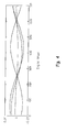
- Frequency analysis logic block 104 performs frequency analysis on the associated signal Ox(CP), block 310. In one embodiment, frequency analysis logic block 104 determines the cycle frequency of the engine from the engine speed signal. Frequency analysis logic block 104 then filters the associated signal Ox(CP) at the cycle frequency. In other embodiments, the associated signal Ox(CP) is filtered at a harmonic frequency of the cycle frequency. In one embodiment, this filtering is carried out via a band filter, such as a notch filter. This analysis provides (filtered) frequency component data regarding the relationship between the exhaust component and the engine angle. In one embodiment, the frequency component data is processed to produce root mean squared data and/or amplitude data of the filtered oxygen content data.
- FIG. 4 shows an exemplary illustration of one embodiment of the output frequency component data. It should be appreciated that the graphical nature of FIG. 4 is provided for ease of comprehension. FIG. 4 actually shows four "curves" representing four sets of measurements. Control computer 42 need not produce such a graphical representation.
- the root mean squared data is compared to a threshold and further processing thereof is conditionally performed based upon the root mean squared data having a value greater than a threshold. Further, embodiments are envisioned where a running average of the root mean squared data over a defined time period (or number of cycles) is used and compared to a threshold rather than instantaneous values.
- Control computer 42 further includes an imbalance determination logic block 110 receiving the frequency component data from logic block 104.
- the imbalance determination logic block 110 is configured to process the received frequency component data and determine whether an imbalance between cylinders 108, 112 is indicated thereby (an "imbalance detector").
- Imbalance determination logic block 110 further operates as a variance analyzer operable to produce a statistical measure of the magnitude of varying in the filtered exhaust parameter data.
- the frequency component data is analyzed to determine amplitude characteristics thereof, block 320.
- the frequency component data is analyzed to determine the point having the greatest amplitude or least amplitude among the data points.
- the frequency component data may be analyzed to determine where the amplitude is zero (or within a threshold distance of zero, or the closest to zero of the data points).
- the analysis provides one or more engine angles along with amplitude data from the frequency component data.
- the determined point(s) is then used to identify one or more cylinders that are experiencing an imbalance, block 340. It should be appreciated that while only two cylinders are shown in FIG. 1 , engines 12 often have more (4, 6, 8, 10, 12, etc.) such that many of the cylinders can be balanced while one or more is imbalanced relative to the others.
- the identification of the one or more cylinders is illustratively achieved by comparing the determined points to a lookup table that associates the provided angle to one or more cylinders.
- a formula or other manner of correlating the engine angle to a cylinder is utilized. It should be appreciated that such a table or formula is obtained by experimentation where imbalances are purposefully introduced and their effect on the exhaust parameter is noted.
- correlating the engine angle to a cylinder imbalance pattern is achieved by actively varying the fuelling in each cylinder and determining the points that are most sensitive to the observed amplitude. In order to obtain better signal to noise characteristics, fuel can be varied at specific frequencies and the sensitivity to the output at the same frequency can be determined.
- the amplitude of the data is indicative of the severity of imbalance.
- the amplitude of the data is compared to a threshold. Further processing of the data is conditionally performed based upon the maximum amplitude having a value greater than a threshold.
- the imbalance determination logic block 110 the frequency component data received from frequency analysis logic block 104 is processed to perform shape analysis on the curve provided by the data, block 330.
- Shape analysis is illustratively a form of pattern matching.
- shape analysis is one of comparing the curve to one or more reference curves and obtaining a root mean squared value that describes the cumulative differences therebetween or a dot product to describe the similarity between them.
- shape analysis utilizes a neural network type application to associate the frequency component data with a cylinder experiencing an imbalance.
- shape analysis is performed by sampling the provided data at pre-defined engine angles. Again, the shape analysis application is trained by providing examples of balanced and imbalanced frequency component data.
- the shape analysis includes use of linear discriminant analysis and support vector machines to transform the signal appropriately and then identify the imbalance pattern.
- the pattern matching produces a value indicative of the degree of matching for the shape of the filtered exhaust parameter content data and further processing is conditionally performed based upon the degree of matching having a value greater than a threshold. Having determined the cylinder(s) experiencing the imbalance and the severity of the imbalance, this data is output from imbalance determination logic 110 to fueling alteration logic block 107.
- Fueling alteration logic block 107 receives the data regarding the imbalance and determines fueling alterations to reduce and/or eliminate the imbalance. It should be appreciated that in some embodiments, the fueling alteration logic block 107 employs a threshold test such that if the severity of the imbalance is small or below the threshold, no corrective action is taken. In those embodiments and/or situations where the provided imbalance data calls for alteration of the fueling, fueling alteration values (FC A ) are output from fueling alteration logic block 107 to second cylinder 112.
- Final fueling logic block 112 receives FC D and FC A and determines (such as by adding) the final fueling command (FC) which is output via signal paths 88 to fuel system 86.
- the fueling system 86 is responsive to the fueling command, FC, to supply fuel to engine 12 as described hereinabove.
- a first aspect of the present invention provides a method of detecting a fueling imbalance in an internal combustion engine including: receiving data regarding an oxygen content of engine exhaust for the engine operating at a cycle rate; performing frequency component analysis comprising a filtering operation on the received oxygen content data at one or more frequencies taken from the group consisting the cycle rate of the engine and harmonics thereof to obtain filtered oxygen content data; determining at least one of:
- the method may further include processing the filtered oxygen content to obtain at least one of root mean squared data and amplitude data of the filtered oxygen content data.
- the method may further include comparing the root mean squared data to a threshold and the determining and identifying are conditionally performed based upon the root mean squared data having a value greater than the threshold.
- identifying a cylinder experiencing a fueling imbalance may include comparing the determined angles and associated amplitude to a table of such values to identify a cylinder.
- identifying a cylinder experiencing a fueling imbalance may include conducting pattern matching analysis on the determined shape of the filtered oxygen content data.
- the pattern matching may be performed using a model selected from the group of linear discriminant analysis and support vector machines.
- the pattern matching may produce a value indicative of the degree of matching for the shape of the filtered oxygen content and the determining and identifying may be conditionally performed based upon the degree of matching value having a value greater than a threshold.
- the method may further include issuing a corrective fueling command to the identified cylinder.
- the method may further include:
- the first amplitude value characteristic may be defined as one or more of greatest amplitude, least amplitude, and closest to zero amplitude.
- the method may further include:
- Fuelling in a first cylinder may be modified such that corresponding changes in the filtered oxygen content data are noted to identify a correlation between imbalance and the filtered oxygen content data.
- a second aspect of the present invention provides a device for detecting a fueling imbalance in an internal combustion engine including: an oxygen sensor operable to detect oxygen content in engine exhaust of the engine operating at a cycle rate; a frequency analyzer operable to receive data from the oxygen sensor and filter the received data at one or more frequencies taken from the group consisting the cycle rate of the engine and harmonics thereof to obtain filtered oxygen content data; at least one of:
- the device may further include a variance analyzer operable to produce a statistical measure of the magnitude of varying filtered oxygen content data.
- the variance analyzer may perform a root mean square calculation on the filtered oxygen content data.
- the imbalance detector may identify a cylinder experiencing a fueling imbalance by comparing the determined angles and associated amplitude to a table of such values.
- the imbalance detector may identify a cylinder experiencing a fueling imbalance by conducting pattern matching analysis on the determined shape of the filtered oxygen content data.
- the device may further include a fueling command module that issues a fueling command responsive to a fueling imbalance signal issued by the imbalance detector.
- the first amplitude value characteristic may be defined as one or more of greatest amplitude, least amplitude, and zero amplitude.
- a third aspect of the present invention provides an engine control module including memory having non transitory instructions thereon that when interpreted by the engine control module cause the module to:
- the instructions may further cause the module to output a fueling command responsive to the identification of the cylinder experiencing a fueling imbalance.
- the instructions may further cause the module to produce a statistical measure of the magnitude of variance in the filtered oxygen content data.
- the instructions may further cause the module to compare the determined angles and associated amplitude to a table of such values to identify the cylinder experiencing a fueling imbalance.
- the instructions may further cause the module to identify the cylinder experiencing a fueling imbalance by conducting a pattern matching analysis on the determined shape of the filtered oxygen content data.
- the first amplitude value characteristic may be defined as one or more of greatest amplitude, least amplitude, and zero amplitude.
Landscapes
- Engineering & Computer Science (AREA)
- Chemical & Material Sciences (AREA)
- Combustion & Propulsion (AREA)
- Mechanical Engineering (AREA)
- General Engineering & Computer Science (AREA)
- Physics & Mathematics (AREA)
- General Physics & Mathematics (AREA)
- Combined Controls Of Internal Combustion Engines (AREA)
- Electrical Control Of Air Or Fuel Supplied To Internal-Combustion Engine (AREA)
Applications Claiming Priority (1)
| Application Number | Priority Date | Filing Date | Title |
|---|---|---|---|
| US14/290,052 US10030593B2 (en) | 2014-05-29 | 2014-05-29 | System and method for detecting air fuel ratio imbalance |
Publications (3)
| Publication Number | Publication Date |
|---|---|
| EP2949906A2 true EP2949906A2 (de) | 2015-12-02 |
| EP2949906A3 EP2949906A3 (de) | 2016-01-27 |
| EP2949906B1 EP2949906B1 (de) | 2025-12-31 |
Family
ID=53365758
Family Applications (1)
| Application Number | Title | Priority Date | Filing Date |
|---|---|---|---|
| EP15169046.8A Active EP2949906B1 (de) | 2014-05-29 | 2015-05-22 | System und verfahren zur detektion der unausgeglichenheit des luft-kraftstoff-verhältnisses |
Country Status (3)
| Country | Link |
|---|---|
| US (1) | US10030593B2 (de) |
| EP (1) | EP2949906B1 (de) |
| CN (1) | CN105298669B (de) |
Cited By (1)
| Publication number | Priority date | Publication date | Assignee | Title |
|---|---|---|---|---|
| WO2020006047A1 (en) * | 2018-06-29 | 2020-01-02 | Fca Us Llc | Pre-turbine wide-range oxygen sensor lambda control during scavenging |
Families Citing this family (9)
| Publication number | Priority date | Publication date | Assignee | Title |
|---|---|---|---|---|
| US9885305B2 (en) * | 2016-02-24 | 2018-02-06 | Ford Global Technologies, Llc | Method for reducing cylinder air-fuel ratio imbalance |
| US9874167B2 (en) * | 2016-06-08 | 2018-01-23 | GM Global Technology Operations LLC | Control systems and methods for air fuel imbalance and cylinder deactivation |
| US20210310433A1 (en) * | 2016-09-27 | 2021-10-07 | Cummins Inc. | System and methods for combustion controls in multi-cylinder opposed piston engines |
| WO2018102583A1 (en) | 2016-12-01 | 2018-06-07 | Cummins Inc. | Internal combustion engine cylinder air-fuel ratio imbalance detection and controls |
| JP6569689B2 (ja) * | 2017-01-11 | 2019-09-04 | トヨタ自動車株式会社 | エンジン装置 |
| CN111886552B (zh) * | 2017-06-08 | 2024-03-26 | 康明斯公司 | 用于隔离车辆的失效模式的诊断系统和方法 |
| KR102406041B1 (ko) * | 2017-12-27 | 2022-06-08 | 현대자동차주식회사 | 기통간 공연비 편차 진단 방법 |
| US11512660B2 (en) * | 2019-06-17 | 2022-11-29 | Cummins Inc. | Internal combustion engine misfire and air-fuel ratio imbalance detection and controls |
| US11168627B2 (en) * | 2019-11-18 | 2021-11-09 | GM Global Technology Operations LLC | Cylinder imbalance correction system and method |
Citations (2)
| Publication number | Priority date | Publication date | Assignee | Title |
|---|---|---|---|---|
| WO2003001175A1 (en) * | 2001-06-26 | 2003-01-03 | Engines Pdm Ltd. | Universal diagnostic method and system for engines |
| DE102008054215A1 (de) * | 2008-10-31 | 2010-05-06 | Bayerische Motoren Werke Aktiengesellschaft | Verfahren zur Vertrimmungsbestimmung einer Brennkraftmaschine mit zumindest zwei Brennkammern |
Family Cites Families (41)
| Publication number | Priority date | Publication date | Assignee | Title |
|---|---|---|---|---|
| US5651353A (en) * | 1996-05-03 | 1997-07-29 | General Motors Corporation | Internal combustion engine control |
| US6382198B1 (en) | 2000-02-04 | 2002-05-07 | Delphi Technologies, Inc. | Individual cylinder air/fuel ratio control based on a single exhaust gas sensor |
| US6314952B1 (en) * | 2000-03-23 | 2001-11-13 | General Motors Corporation | Individual cylinder fuel control method |
| JP4205030B2 (ja) * | 2003-10-06 | 2009-01-07 | 本田技研工業株式会社 | 内燃機関の空燃比制御装置 |
| DE102004030759B4 (de) * | 2004-06-25 | 2015-12-17 | Robert Bosch Gmbh | Verfahren zur Steuerung einer Brennkraftmaschine |
| US7027910B1 (en) * | 2005-01-13 | 2006-04-11 | General Motors Corporation | Individual cylinder controller for four-cylinder engine |
| US7152594B2 (en) * | 2005-05-23 | 2006-12-26 | Gm Global Technology Operations, Inc. | Air/fuel imbalance detection system and method |
| FR2886346B1 (fr) * | 2005-05-30 | 2010-08-27 | Inst Francais Du Petrole | Methode d'estimation par un filtre de kalman etendu de la richesse dans un cylindre d'un moteur a combustion |
| FR2886345B1 (fr) * | 2005-05-30 | 2010-08-27 | Inst Francais Du Petrole | Methode d'estimation par un filtre non-lineaire adaptatif de la richesse dans un cylindre d'un moteur a combustion |
| US7802563B2 (en) * | 2008-03-25 | 2010-09-28 | Fors Global Technologies, LLC | Air/fuel imbalance monitor using an oxygen sensor |
| JP4876107B2 (ja) * | 2008-07-18 | 2012-02-15 | 日立オートモティブシステムズ株式会社 | 内燃機関の診断制御装置 |
| US8577645B2 (en) * | 2008-10-01 | 2013-11-05 | GM Global Technology Operations LLC | Air/fuel mixture imbalance diagnostic systems and methods |
| US7900615B2 (en) | 2008-10-01 | 2011-03-08 | Gm Global Technology Operations, Inc. | Air-fuel imbalance detection based on zero-phase filtering |
| EP2372132B1 (de) | 2008-12-26 | 2018-09-12 | Toyota Jidosha Kabushiki Kaisha | Vorrichtung zur steuerung eines verbrennungsmotors anhand eines verstellbaren ventilmechanismus |
| JP5045820B2 (ja) | 2009-01-28 | 2012-10-10 | トヨタ自動車株式会社 | 多気筒内燃機関の監視装置 |
| CN102301119B (zh) | 2009-01-28 | 2014-03-12 | 丰田自动车株式会社 | 多气缸内燃机的空燃比气缸间失调判定装置 |
| CN102308074B (zh) | 2009-02-03 | 2014-06-25 | 丰田自动车株式会社 | 内燃机的气缸间空燃比不平衡判定装置 |
| CN102472191B (zh) | 2009-07-02 | 2014-10-08 | 丰田自动车株式会社 | 内燃机的气缸间空燃比不平衡判定装置 |
| JP5333058B2 (ja) | 2009-08-27 | 2013-11-06 | トヨタ自動車株式会社 | 内燃機関の空燃比気筒間インバランス判定装置 |
| JP4894980B2 (ja) | 2009-09-08 | 2012-03-14 | トヨタ自動車株式会社 | 多気筒内燃機関の気筒間空燃比インバランス判定装置 |
| WO2011033688A1 (ja) | 2009-09-18 | 2011-03-24 | トヨタ自動車株式会社 | 内燃機関の空燃比気筒間インバランス判定装置 |
| US8670917B2 (en) * | 2009-10-06 | 2014-03-11 | Toyota Jidosha Kabushiki Kaisha | Air-fuel-ratio imbalance determination apparatus for internal combustion engine |
| US8489312B2 (en) | 2009-10-29 | 2013-07-16 | GM Global Technology Operations LLC | Method and system for detecting operating errors in a variable valve timing engine |
| WO2011055463A1 (ja) * | 2009-11-05 | 2011-05-12 | トヨタ自動車株式会社 | 内燃機関の空燃比気筒間インバランス判定装置 |
| JP5170320B2 (ja) | 2009-11-12 | 2013-03-27 | トヨタ自動車株式会社 | 内燃機関の空燃比気筒間インバランス判定装置 |
| US8401766B2 (en) | 2009-12-09 | 2013-03-19 | Toyota Jidosha Kabushiki Kaisha | Inter-cylinder air-fuel ratio imbalance determination apparatus for internal combustion engine |
| US8682569B2 (en) * | 2009-12-17 | 2014-03-25 | GM Global Technology Operations LLC | Systems and methods for diagnosing valve lift mechanisms and oil control valves of camshaft lift systems |
| JP4968492B2 (ja) | 2009-12-18 | 2012-07-04 | トヨタ自動車株式会社 | 内燃機関の空燃比気筒間インバランス判定装置 |
| JP5107392B2 (ja) * | 2010-06-01 | 2012-12-26 | 本田技研工業株式会社 | 気筒間の空燃比の不均衡を判断するための装置 |
| JP5331753B2 (ja) * | 2010-06-04 | 2013-10-30 | 日立オートモティブシステムズ株式会社 | エンジンの制御装置 |
| JP5499978B2 (ja) * | 2010-07-30 | 2014-05-21 | トヨタ自動車株式会社 | 多気筒内燃機関の燃料噴射量制御装置 |
| CN103221661B (zh) | 2010-11-01 | 2015-05-13 | 丰田自动车株式会社 | 气缸间空燃比偏差异常检测装置 |
| JP5278454B2 (ja) | 2011-01-28 | 2013-09-04 | トヨタ自動車株式会社 | 多気筒内燃機関の気筒間空燃比ばらつき異常検出装置 |
| JP5273170B2 (ja) | 2011-02-02 | 2013-08-28 | トヨタ自動車株式会社 | ハイブリッド車両 |
| GB2491146A (en) * | 2011-05-24 | 2012-11-28 | Gm Global Tech Operations Inc | Method for operating an internal combustion engine |
| US9217383B2 (en) * | 2011-09-01 | 2015-12-22 | GM Global Technology Operations LLC | Imbalance re-synchronization control systems and methods |
| JP5261556B2 (ja) * | 2011-10-11 | 2013-08-14 | 本田技研工業株式会社 | 内燃機関の空燃比制御装置 |
| JP5271405B2 (ja) | 2011-11-22 | 2013-08-21 | 本田技研工業株式会社 | 内燃機関の空燃比制御装置 |
| JP5708609B2 (ja) | 2012-03-22 | 2015-04-30 | トヨタ自動車株式会社 | 内燃機関の気筒間の空燃比ばらつき異常検出装置 |
| US20130268177A1 (en) * | 2012-04-05 | 2013-10-10 | Chrysler Group Llc | Individual cylinder fuel air ratio estimation for engine control and on-board diagnosis |
| US9453782B2 (en) * | 2014-07-03 | 2016-09-27 | Continental Automotive Systems, Inc. | Detection of air-fuel ratio rich-lean imbalance using an oxygen sensor |
-
2014
- 2014-05-29 US US14/290,052 patent/US10030593B2/en active Active
-
2015
- 2015-05-22 EP EP15169046.8A patent/EP2949906B1/de active Active
- 2015-05-28 CN CN201510282209.6A patent/CN105298669B/zh active Active
Patent Citations (2)
| Publication number | Priority date | Publication date | Assignee | Title |
|---|---|---|---|---|
| WO2003001175A1 (en) * | 2001-06-26 | 2003-01-03 | Engines Pdm Ltd. | Universal diagnostic method and system for engines |
| DE102008054215A1 (de) * | 2008-10-31 | 2010-05-06 | Bayerische Motoren Werke Aktiengesellschaft | Verfahren zur Vertrimmungsbestimmung einer Brennkraftmaschine mit zumindest zwei Brennkammern |
Cited By (1)
| Publication number | Priority date | Publication date | Assignee | Title |
|---|---|---|---|---|
| WO2020006047A1 (en) * | 2018-06-29 | 2020-01-02 | Fca Us Llc | Pre-turbine wide-range oxygen sensor lambda control during scavenging |
Also Published As
| Publication number | Publication date |
|---|---|
| CN105298669A (zh) | 2016-02-03 |
| EP2949906B1 (de) | 2025-12-31 |
| US20150345416A1 (en) | 2015-12-03 |
| EP2949906A3 (de) | 2016-01-27 |
| CN105298669B (zh) | 2020-07-17 |
| US10030593B2 (en) | 2018-07-24 |
Similar Documents
| Publication | Publication Date | Title |
|---|---|---|
| US10030593B2 (en) | System and method for detecting air fuel ratio imbalance | |
| Kimmich et al. | Fault detection for modern Diesel engines using signal-and process model-based methods | |
| CN102713226B (zh) | 排气回流装置的异常检测装置 | |
| CN112395733B (zh) | 用于修改检测到的凸轮轴位置的方法、控制器、内燃机和车辆 | |
| JP6054925B2 (ja) | 内燃機関の制御装置 | |
| US10208692B2 (en) | Misfire detecting system for engine | |
| WO2018102583A1 (en) | Internal combustion engine cylinder air-fuel ratio imbalance detection and controls | |
| US7380446B2 (en) | Method for determining the rotary speed of a compressor, especially a turbocharger | |
| US11226264B2 (en) | Method for the diagnosis of engine misfires in an internal combustion engine | |
| CN106988907A (zh) | 识别内燃发动机中出现故障的燃料喷射器的方法 | |
| US9587575B2 (en) | Cylinder-to-cylinder variation abnormality detecting device | |
| JP2013053546A (ja) | 過給機の制御装置 | |
| US20070163547A1 (en) | Intake air amount variation detector | |
| WO2015133172A1 (ja) | 内燃機関の空燃比検出装置 | |
| CN117588324A (zh) | 进气流量修正方法、装置、电子设备及存储介质 | |
| JP6550408B2 (ja) | エンジンの失火検出装置及び方法 | |
| KR102330460B1 (ko) | 내연기관의 제어 유닛에서 필터링된 공기 시스템 상태 변수의 공급 방법 및 그 장치 | |
| CN112334751B (zh) | 用于判定与内燃机中的气缸的失火判定有关的可靠性的方法和控制装置 | |
| US20150167560A1 (en) | Variable valve lift diagnostic techniques using an intake manifold absolute pressure signal | |
| JP6020499B2 (ja) | 内燃機関の制御装置 | |
| EP2354501B1 (de) | Steuerungsvorrichtung für einen Verbrennungsmotor | |
| EP2891784A1 (de) | Verbrennungsmotor mit kurbelwellensignalbasierter verbrennungsgeräuschsteuerung | |
| JPS61157741A (ja) | 吸入空気量検出装置 | |
| US9175582B1 (en) | Variable valve lift diagnostic techniques based on camshaft speed | |
| JP2019090330A (ja) | エンジンの吸気圧力推定装置 |
Legal Events
| Date | Code | Title | Description |
|---|---|---|---|
| AK | Designated contracting states |
Kind code of ref document: A2 Designated state(s): AL AT BE BG CH CY CZ DE DK EE ES FI FR GB GR HR HU IE IS IT LI LT LU LV MC MK MT NL NO PL PT RO RS SE SI SK SM TR |
|
| AX | Request for extension of the european patent |
Extension state: BA ME |
|
| PUAI | Public reference made under article 153(3) epc to a published international application that has entered the european phase |
Free format text: ORIGINAL CODE: 0009012 |
|
| PUAL | Search report despatched |
Free format text: ORIGINAL CODE: 0009013 |
|
| AK | Designated contracting states |
Kind code of ref document: A3 Designated state(s): AL AT BE BG CH CY CZ DE DK EE ES FI FR GB GR HR HU IE IS IT LI LT LU LV MC MK MT NL NO PL PT RO RS SE SI SK SM TR |
|
| AX | Request for extension of the european patent |
Extension state: BA ME |
|
| RIC1 | Information provided on ipc code assigned before grant |
Ipc: F02D 41/14 20060101ALI20151218BHEP Ipc: F02D 41/00 20060101AFI20151218BHEP |
|
| 17P | Request for examination filed |
Effective date: 20160726 |
|
| RBV | Designated contracting states (corrected) |
Designated state(s): AL AT BE BG CH CY CZ DE DK EE ES FI FR GB GR HR HU IE IS IT LI LT LU LV MC MK MT NL NO PL PT RO RS SE SI SK SM TR |
|
| STAA | Information on the status of an ep patent application or granted ep patent |
Free format text: STATUS: EXAMINATION IS IN PROGRESS |
|
| 17Q | First examination report despatched |
Effective date: 20181206 |
|
| P01 | Opt-out of the competence of the unified patent court (upc) registered |
Effective date: 20230510 |
|
| RIC1 | Information provided on ipc code assigned before grant |
Ipc: F02D 41/00 20060101AFI20250812BHEP Ipc: F02D 41/14 20060101ALI20250812BHEP |
|
| GRAP | Despatch of communication of intention to grant a patent |
Free format text: ORIGINAL CODE: EPIDOSNIGR1 |
|
| STAA | Information on the status of an ep patent application or granted ep patent |
Free format text: STATUS: GRANT OF PATENT IS INTENDED |
|
| INTG | Intention to grant announced |
Effective date: 20250929 |
|
| GRAS | Grant fee paid |
Free format text: ORIGINAL CODE: EPIDOSNIGR3 |
|
| GRAA | (expected) grant |
Free format text: ORIGINAL CODE: 0009210 |
|
| STAA | Information on the status of an ep patent application or granted ep patent |
Free format text: STATUS: THE PATENT HAS BEEN GRANTED |
|
| AK | Designated contracting states |
Kind code of ref document: B1 Designated state(s): AL AT BE BG CH CY CZ DE DK EE ES FI FR GB GR HR HU IE IS IT LI LT LU LV MC MK MT NL NO PL PT RO RS SE SI SK SM TR |
|
| REG | Reference to a national code |
Ref country code: CH Ref legal event code: F10 Free format text: ST27 STATUS EVENT CODE: U-0-0-F10-F00 (AS PROVIDED BY THE NATIONAL OFFICE) Effective date: 20251231 Ref country code: GB Ref legal event code: FG4D |
|
| REG | Reference to a national code |
Ref country code: DE Ref legal event code: R096 Ref document number: 602015092862 Country of ref document: DE |
|
| REG | Reference to a national code |
Ref country code: IE Ref legal event code: FG4D |
|
| REG | Reference to a national code |
Ref country code: LT Ref legal event code: MG9D |
|
| PG25 | Lapsed in a contracting state [announced via postgrant information from national office to epo] |
Ref country code: NO Free format text: LAPSE BECAUSE OF FAILURE TO SUBMIT A TRANSLATION OF THE DESCRIPTION OR TO PAY THE FEE WITHIN THE PRESCRIBED TIME-LIMIT Effective date: 20260331 |
|
| PG25 | Lapsed in a contracting state [announced via postgrant information from national office to epo] |
Ref country code: HR Free format text: LAPSE BECAUSE OF FAILURE TO SUBMIT A TRANSLATION OF THE DESCRIPTION OR TO PAY THE FEE WITHIN THE PRESCRIBED TIME-LIMIT Effective date: 20251231 Ref country code: FI Free format text: LAPSE BECAUSE OF FAILURE TO SUBMIT A TRANSLATION OF THE DESCRIPTION OR TO PAY THE FEE WITHIN THE PRESCRIBED TIME-LIMIT Effective date: 20251231 |
|
| PG25 | Lapsed in a contracting state [announced via postgrant information from national office to epo] |
Ref country code: RS Free format text: LAPSE BECAUSE OF FAILURE TO SUBMIT A TRANSLATION OF THE DESCRIPTION OR TO PAY THE FEE WITHIN THE PRESCRIBED TIME-LIMIT Effective date: 20260331 |
|
| PG25 | Lapsed in a contracting state [announced via postgrant information from national office to epo] |
Ref country code: LV Free format text: LAPSE BECAUSE OF FAILURE TO SUBMIT A TRANSLATION OF THE DESCRIPTION OR TO PAY THE FEE WITHIN THE PRESCRIBED TIME-LIMIT Effective date: 20251231 |