EP2949028B1 - Rotierende elektrische maschine - Google Patents
Rotierende elektrische maschine Download PDFInfo
- Publication number
- EP2949028B1 EP2949028B1 EP14704073.7A EP14704073A EP2949028B1 EP 2949028 B1 EP2949028 B1 EP 2949028B1 EP 14704073 A EP14704073 A EP 14704073A EP 2949028 B1 EP2949028 B1 EP 2949028B1
- Authority
- EP
- European Patent Office
- Prior art keywords
- circuit board
- sheet metal
- metal tongue
- tongue
- electric machine
- Prior art date
- Legal status (The legal status is an assumption and is not a legal conclusion. Google has not performed a legal analysis and makes no representation as to the accuracy of the status listed.)
- Not-in-force
Links
Images


Classifications
-
- H—ELECTRICITY
- H02—GENERATION; CONVERSION OR DISTRIBUTION OF ELECTRIC POWER
- H02K—DYNAMO-ELECTRIC MACHINES
- H02K5/00—Casings; Enclosures; Supports
- H02K5/04—Casings or enclosures characterised by the shape, form or construction thereof
- H02K5/22—Auxiliary parts of casings not covered by groups H02K5/06-H02K5/20, e.g. shaped to form connection boxes or terminal boxes
- H02K5/225—Terminal boxes or connection arrangements
-
- H—ELECTRICITY
- H02—GENERATION; CONVERSION OR DISTRIBUTION OF ELECTRIC POWER
- H02K—DYNAMO-ELECTRIC MACHINES
- H02K11/00—Structural association of dynamo-electric machines with electric components or with devices for shielding, monitoring or protection
- H02K11/01—Structural association of dynamo-electric machines with electric components or with devices for shielding, monitoring or protection for shielding from electromagnetic fields, i.e. structural association with shields
- H02K11/014—Shields associated with stationary parts, e.g. stator cores
- H02K11/0141—Shields associated with casings, enclosures or brackets
-
- H—ELECTRICITY
- H02—GENERATION; CONVERSION OR DISTRIBUTION OF ELECTRIC POWER
- H02K—DYNAMO-ELECTRIC MACHINES
- H02K11/00—Structural association of dynamo-electric machines with electric components or with devices for shielding, monitoring or protection
- H02K11/30—Structural association with control circuits or drive circuits
- H02K11/33—Drive circuits, e.g. power electronics
-
- H—ELECTRICITY
- H02—GENERATION; CONVERSION OR DISTRIBUTION OF ELECTRIC POWER
- H02K—DYNAMO-ELECTRIC MACHINES
- H02K11/00—Structural association of dynamo-electric machines with electric components or with devices for shielding, monitoring or protection
- H02K11/40—Structural association with grounding devices
-
- H—ELECTRICITY
- H05—ELECTRIC TECHNIQUES NOT OTHERWISE PROVIDED FOR
- H05K—PRINTED CIRCUITS; CASINGS OR CONSTRUCTIONAL DETAILS OF ELECTRIC APPARATUS; MANUFACTURE OF ASSEMBLAGES OF ELECTRICAL COMPONENTS
- H05K1/00—Printed circuits
- H05K1/02—Details
- H05K1/0213—Electrical arrangements not otherwise provided for
-
- H—ELECTRICITY
- H05—ELECTRIC TECHNIQUES NOT OTHERWISE PROVIDED FOR
- H05K—PRINTED CIRCUITS; CASINGS OR CONSTRUCTIONAL DETAILS OF ELECTRIC APPARATUS; MANUFACTURE OF ASSEMBLAGES OF ELECTRICAL COMPONENTS
- H05K1/00—Printed circuits
- H05K1/18—Printed circuits structurally associated with non-printed electric components
-
- H—ELECTRICITY
- H05—ELECTRIC TECHNIQUES NOT OTHERWISE PROVIDED FOR
- H05K—PRINTED CIRCUITS; CASINGS OR CONSTRUCTIONAL DETAILS OF ELECTRIC APPARATUS; MANUFACTURE OF ASSEMBLAGES OF ELECTRICAL COMPONENTS
- H05K3/00—Apparatus or processes for manufacturing printed circuits
- H05K3/30—Assembling printed circuits with electric components, e.g. with resistor
- H05K3/32—Assembling printed circuits with electric components, e.g. with resistor electrically connecting electric components or wires to printed circuits
- H05K3/325—Assembling printed circuits with electric components, e.g. with resistor electrically connecting electric components or wires to printed circuits by abutting or pinching, i.e. without alloying process; mechanical auxiliary parts therefor
-
- H—ELECTRICITY
- H05—ELECTRIC TECHNIQUES NOT OTHERWISE PROVIDED FOR
- H05K—PRINTED CIRCUITS; CASINGS OR CONSTRUCTIONAL DETAILS OF ELECTRIC APPARATUS; MANUFACTURE OF ASSEMBLAGES OF ELECTRICAL COMPONENTS
- H05K3/00—Apparatus or processes for manufacturing printed circuits
- H05K3/40—Forming printed elements for providing electric connections to or between printed circuits
- H05K3/4007—Surface contacts, e.g. bumps
- H05K3/4015—Surface contacts, e.g. bumps using auxiliary conductive elements, e.g. pieces of metal foil, metallic spheres
-
- H—ELECTRICITY
- H02—GENERATION; CONVERSION OR DISTRIBUTION OF ELECTRIC POWER
- H02K—DYNAMO-ELECTRIC MACHINES
- H02K2211/00—Specific aspects not provided for in the other groups of this subclass relating to measuring or protective devices or electric components
- H02K2211/03—Machines characterised by circuit boards, e.g. pcb
-
- H—ELECTRICITY
- H05—ELECTRIC TECHNIQUES NOT OTHERWISE PROVIDED FOR
- H05K—PRINTED CIRCUITS; CASINGS OR CONSTRUCTIONAL DETAILS OF ELECTRIC APPARATUS; MANUFACTURE OF ASSEMBLAGES OF ELECTRICAL COMPONENTS
- H05K2201/00—Indexing scheme relating to printed circuits covered by H05K1/00
- H05K2201/10—Details of components or other objects attached to or integrated in a printed circuit board
- H05K2201/10227—Other objects, e.g. metallic pieces
- H05K2201/10295—Metallic connector elements partly mounted in a hole of the PCB
- H05K2201/10303—Pin-in-hole mounted pins
-
- H—ELECTRICITY
- H05—ELECTRIC TECHNIQUES NOT OTHERWISE PROVIDED FOR
- H05K—PRINTED CIRCUITS; CASINGS OR CONSTRUCTIONAL DETAILS OF ELECTRIC APPARATUS; MANUFACTURE OF ASSEMBLAGES OF ELECTRICAL COMPONENTS
- H05K3/00—Apparatus or processes for manufacturing printed circuits
- H05K3/40—Forming printed elements for providing electric connections to or between printed circuits
- H05K3/4038—Through-connections; Vertical interconnect access [VIA] connections
- H05K3/4046—Through-connections; Vertical interconnect access [VIA] connections using auxiliary conductive elements, e.g. metallic spheres, eyelets, pieces of wire
Definitions
- the invention is in the field of electrical engineering and relates specifically to rotating electrical machines, such as electric motors and generators.
- Electric motors are increasingly used in the automotive industry, but also in other fields of technology, where more and more electric drive units are introduced to increase safety or comfort. Often used as electric motors so-called brushless motors that are particularly good and efficient controllable. Such motors have a stator with an electrical winding, which is suitably driven to produce a rotating magnetic field, wherein in the rotating electric field, a rotor driven by this moves.
- PWM pulse width modulation
- the invention has for its object to provide a rotating electrical machine, which is particularly well and efficiently electrically shielded to minimize the emission of electromagnetic signals.
- the machine should be as insensitive as possible to surges or voltage flashovers.
- the object is achieved with the features of the invention according to claim 1.
- the rotating electrical machine also has a connection device which has at least one coupling element for electrical connection of the drive device with one or more electrical lines and a ground element provided for connection to an electrical ground potential.
- the shield plate is electrically conductively connected by means of a metal tongue via a first electrical pressure contact with the mass element.
- the electronic control device of the electrical machine typically has field-effect transistors, IGBTs, thyristors or similar semiconductor elements or semiconductor switches for generating a pulse-width-modulated signal or generally an electrical signal suitable for driving the winding of the machine.
- the control device is connected by means of a connection device with corresponding units for power supply and control.
- the connection device has, for example, a coupling element in the form of a plug connection.
- a mass element is provided, which also either via a connector or can be connected to a ground potential via a permanently installed ground line.
- the corresponding mass element can be, for example, the plug housing or a corresponding pole of a plug connection. It can also be provided that a frame, a support frame or a support frame of the electrical machine forms the mass element.
- the elements of the shield of the electric machine are connected as short as possible with the mass element.
- the contact resistance in the conductive connection to the mass element should be as low as possible. This causes in addition to a reliable shielding of fields and waves and the easy and fast dissipation of surges, which can pass, for example, by electrical flashovers on parts of the shield, for example, when charged particles come in the course of a cooling air flow in contact with parts of the electric machine.
- the shield plate which is part of the shield of the electrical machine, reliably conductively connect to the ground element.
- the pressure contact device is durable and reliable to produce and easily compensates for manufacturing and assembly tolerances.
- both the terminal device and electronic components are mounted on the same side of a printed circuit board, which faces away from the screen plate.
- an electrical conductor such as the metal tongue according to the invention, is directly connected or contacted with a mass element and this sheet metal tongue passes directly through the plane the circuit board is guided through to the screen plate.
- the shield plate is usually formed by a metal plate, which extends at least in parts, advantageously substantially or even completely in the immediate vicinity of a circuit board of the drive device. In such a case, the shield plate can also have the function of a heat sink for the drive device in addition to its shield effect.
- the shield plate can be mechanically connected for this purpose also at one or more locations with the circuit board of the drive means for the transfer of heat.
- this in the region in which the first electrical pressure contact between the metal tongue and the shield plate is formed, this a depression, z. B. in the form of a bead, so that there is formed a distance or an increased distance between the shield plate and provided in the drive circuit board.
- the shield plate may also have a raised edge which surrounds a printed circuit board located in the immediate vicinity of the shield plate and thereby shields and protects. It can also be clamped, for example, for contacting the shield plate with the mass element, a resilient rider on an edge portion of the shield plate, which has a metal tongue which is resiliently pressed against a conductor of a circuit board of the control device or directly against the mass element.
- the sheet metal tongue is conductively connected to the mass element by means of a connecting conductor which is in electrical contact with the latter by a pressure contact.
- the sheet metal tongue can be resiliently pressed against a connecting conductor, which according to the invention forms or comprises a section of a conductor track of the drive device.
- the invention can advantageously be configured in that the control device has a printed circuit board with conductor tracks, and that the metal tongue passes through the plane of the circuit board, in particular a recess in the circuit board and mechanically held in a clamping device and electrically connected to the mass element or to the shield plate is.
- the clamping device may for example lie on one side of the printed circuit board, which faces away from the screen plate.
- the clamping device can be attached to the drive device and supported by this.
- the clamping device may be attached to the circuit board.
- the clamping device can also be completely supported by the mass element and connected rigidly thereto.
- the clamping device comprises a plurality of elements, wherein an element, in particular an insulating element, the clamping device is advantageously connected to the circuit board. This makes it clear that a conductive connection between the clamping device and the sheet metal tongue on the one hand and the circuit board can be provided, however, is not necessary for contacting the shield plate with the mass element in all embodiments. It can also be advantageously provided that at least one element of the clamping device is rigidly connected to the mass element.
- the clamping device may be supported by the mass element, for example by means of a metal strip and secured thereto and at the same time be electrically contacted by this connection.
- the metal tongue extends substantially in a longitudinal direction and the clamping device at least one Guide rail, in which the metal tongue is guided in its longitudinal direction displaceable.
- the guide rail may be formed as an electrically conductive element and in addition to the mechanical guide function and the function of the electrical contacting of the tongue tongue meet.
- the clamping device as a further element on an abutment through which the metal tongue is pressed against the guide rail.
- the anvil may for example be formed as an electrically insulating component and connected to the circuit board.
- the metal tongue can then be held in frictional engagement between the anvil and the guide rail and pressed during assembly while applying the necessary force against the shield plate. Due to the inherent elasticity of the metal tongue, the pressure contact between this and the shield plate can be maintained.
- a latching connection which determines the sheet metal tongue in the guide rail.
- the latching connection can be provided between the sheet metal tongue on the one hand and the counter-bearing on the other hand, but also between the sheet metal tongue and a recess or elevation of the guide rail. It can also be provided a ausbiegbare latching tab on the tongue.
- the electrical connection between the grounding element and the shielding plate does not involve a conductor section formed as a printed circuit board on a printed circuit board, wherein the printed circuit guide is guided completely independently of the printed circuit board and the printed circuit board passes through the section of the connecting line formed as a metal tongue is, can be advantageously provided that the metal tongue cooperates by a second pressure contact piece with a conductor track of the printed circuit board in a pressure contact connection and electrically connects them via the metal tongue with the mass element.
- the sheet metal tongue can advantageously also have at least two parts, a front and a rear sheet metal strip, which are mutually displaceable in the longitudinal direction.
- a locking tab of a metal strip between a deflected locking position and a non-deflected position can be moved by the displacement of the metal strip against each other.
- the stator and rotor of the motor are at ground potential.
- the rotary electric machine is brushless.
- the stator is not electrically contacted to the rotor by means of brushes or the like. In this way, electromagnetic interference is further reduced.
- the electrical contact between the rotor and the stator when the stator and rotor are at least partially at ground potential, not by means of the brushes. Consequently, there is the necessary contact via the bearing between the rotor and the stator.
- the sheet tongue is fixed by means of a latching tongue on the circuit board, which engages behind the circuit board, and which is suitably located on the screen plate facing side of the circuit board.
- the cross section of the metal tongue is substantially U-shaped, wherein within this contour, for example, an element of a clamping device is arranged.
- the tongue is clamped to this element, which allows a particularly simple attachment of the tongue.
- a free end of the sheet metal tongue is inserted into a slot of the clamping device and is held there in a non-positive manner.
- the metal tongue is at a free end, which in particular is opposite to the pressure contact, under education cut two legs, which rest in the assembled state, for example, substantially flat on the circuit board.
- the two legs are angled.
- the electrical contact between the metal tongue, in particular its leg, and the circuit board is advantageously realized by means of an applied on the circuit board limiting ring of an electrically conductive material.
- the restriction ring forms the boundary of a hole made in the circuit board.
- the sheet metal tongue on a clip which is suitably arranged at a free end, which is in particular opposite to the pressure contact.
- the clamp is connected, for example, to the mass element, the coupling element or other components of the connection device, wherein the corresponding component is in particular held non-positively between two clamping legs of the clamp. This allows a comparatively simple and quick installation of the tongue.
- the invention relates except to a rotary electric machine according to the above with a shield plate and a mass element and with a compound of the shield plate with the mass element by means of a metal tongue on a control for an electric machine, with a circuit board and with a plane the printed circuit board passing through, held in a clamping device and connected to a ground potential elastic sheet metal tongue, which is adapted to produce an electrical pressure contact with an adjacent conductive plate of the printed circuit board.
- Such a control device is usually suitable for mounting with a corresponding electric machine, but can be built separately from this, prepared and transported.
- the use of such a control device for various types of electrical machines is conceivable, the type of control can be adjusted by appropriate design or adjustment and initialization of the control device.
- Fig. 1 shows an overview in a longitudinal section of an electric machine using the example of a brushless electric motor.
- a brushless electric motor with an inner stator 3 and an outer rotor 4 is shown.
- the internal stator is connected to a front end shield 5.
- a first bearing 6 and a second bearing 7 which may be formed the same in each case in the left and right half section, a shaft 8 rotatably mounted.
- the outer rotor 4 In the machine shown in the left half section of the outer rotor 4 is connected by means of webs or a bell-like device 9 with the shaft 8 and supported by this.
- the outer rotor 4 can still be mounted on the bearing plate 5 by means of a rolling bearing, not shown.
- an electric motor is shown with an inner rotor, so that the rotor 4 'is located radially inside the stator 3'.
- the stator 3 ' is fixedly connected to the bearing plate 5 as well as, for example, with another bearing plate 10th
- the stator 3, 3 ' is in each case provided with a winding 52a, 52b, which surrounds one or more cores and is connected in a manner not shown via control lines to a control device 12
- the shaft 8 is rotatably supported by means of bearings 6, 7. With the shaft 8 also the inner rotor 4 'is firmly connected.
- the drive device 12 which has a printed circuit board 13 and electronic components 14, 15 arranged thereon.
- a shield plate 17 is arranged, which is at least partially made of metal or metallized and which has an upwardly to the circuit board flanged edge 18.
- the shield plate 17 can also serve as a heat sink for the drive device 12 and be firmly connected to the circuit board 13.
- the drive device 12 is connected to a connection device 19 which, inter alia, has a coupling element for electrical connection to lines in the form of a part of a connector 20.
- the housing of the connector 20 is connected in the example shown with ground potential and may form a ground element.
- the double contour 21 forms a bell-shaped cover which is additionally closed on its open side by the shield plate 17, so that the electromagnetically radiating parts of the stator and rotor to the outside donate no or as little as possible electromagnetic radiation.
- the shield plate 17 especially the drive means 12 is particularly well shielded from the winding of the motor.
- the double contour 21 may, for example, be formed as an overall contour by the grounded parts of the stator and rotor of the motor, but it may also consist of an additional metallized component which surrounds said components of the motor. It may also be a motor housing, for example.
- the double contour 21 need not necessarily designate a concrete component, but can only symbolize the electromagnetic shielding function guaranteed by the present invention.
- the shield plate 17 should be connected to a mass element of the connection device which is at ground potential with the lowest possible electrical resistance and as short as possible.
- a mass element of the connection device which is at ground potential with the lowest possible electrical resistance and as short as possible.
- This is one in the Fig. 1 only schematically indicated sheet metal tongue 22 is provided, which is connected to the connection device by a short path and in turn produces an electrical pressure contact with the shield plate 17.
- the metal tongue 22 passes through the plane of the circuit board 13.
- the circuit board 13 has a through opening 23.
- This compound has a contact bridge 24, which is electrically conductive reliably and effectively contacted with the shield plate 17 on the one hand and the bearing plate 5 on the other hand and on the other hand has sufficient flexibility to manufacturing tolerances during assembly of the motor on the one hand and movements in the Compensation operation between the shield plate 17 and the drive means 12 and stator and rotor of the motor on the other hand.
- Fig. 2 shows in a three-dimensional view of the circuit board 13 and this passing through sheet metal tongue 22 which contacts the screen plate 17 below the circuit board 13 by means of a pressure contact.
- the circuit board 13 and the shield plate 17 are only partially shown.
- the sheet metal tongue 22 is shown as a flat, elastically flexible sheet-metal body which has an arc-shaped pressure contact piece 22a at its end facing the screen plate 17. This is elastically deformable, so that by means of the pressure contact piece 22a by the compensation of tolerances a durable and secure pressure contact with the shield plate 17 can be made with an elastic contact force by elastic deformation of the tongue.
- the metal tongue 22 is advantageously mechanically held in a clamping device 25 on the one hand and electrically contacted on the other hand.
- the clamping device 25 is therefore advantageously at least partially made of a highly conductive metal.
- the tongue is either frictionally, i. held by friction or by means of a latching and in particular in the direction perpendicular to the surface of the printed circuit board 13, as indicated by the double arrow 26, fixed.
- the clamping device 25 is connected by means of a connecting lug 27 with a mass element of the connection device 19.
- the contact lug may be formed as a rigid metal sheet, which is connected to the clamping device 25 in one piece or by a glued, soldered or welded connection and in a in the Fig. 2 not shown manner stiff with the on Ground potential lying housing of the coupling element 20, that is, for example, a female connector is connected.
- the clamping device 25 may be fixed on the circuit board, but it can also be compared with this movable and not connected to this and held exclusively by the contact lug 27.
- the sheet metal tongue In the guide channel 25a formed in the clamping device 25 for the sheet metal tongue 22, which is a guide rail for the sheet metal tongue 22, the sheet metal tongue can be positively clamped by an attached metallic or plastic part in the lateral direction perpendicular to the direction of the double arrow 26.
- the sheet metal tongue 22 may also have a bent portion which can be clamped within the guide channel 25a.
- a plastic part of the locking device with the circuit board 13 or with parts of the clamping device to be firmly connected for example, a plastic part of the locking device with the circuit board 13 or with parts of the clamping device to be firmly connected.
- a ground conductor provided there in the form of a conductor track can also be contacted with the metal tongue 22 in the plane of the printed circuit board 13.
- the mass element is otherwise connected to a short path to the circuit board and the metal tongue 22 exclusively via the conductor track of the circuit board 13 is connected to the mass element.
- the sheet metal tongue 22 serves to establish a conductive connection between the ground potential of the printed circuit board 13 and the shield plate 17.
- the contact lug 27 can also be realized by a flexible conductor.
- the opening 23 in the printed circuit board, through which the sheet metal tongue 22 extends, may also lie, for example, on the edge of the printed circuit board 13 and be open toward the edge, ie represent only a lateral recess of the printed circuit board 13.
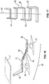
- the Fig. 3 shows in a three-dimensional view of an electric motor with a housing 50 and a drive device 12 with a printed circuit board 13 and arranged in the figure below the circuit board 13 screen plate 17 with flanged edge 18.
- the shield plate 17 may, for example, with the circuit board 13 are in close contact, so that the shield plate 17 can serve as a heat sink for the electronic components of the circuit board 13 at the same time.
- the shield plate 17 is connected to the housing 50 in a manner not shown.
- various electronic components 14, 15 are visible, among which are, for example, thyristors, IGBTs or similar semiconductor components which make it possible to drive the winding of the motor by high-frequency pulse-width modulated signals.
- connection device 19 recognizable with a coupling element 20 in the form of part of a plug connection, wherein the coupling element 20 is formed as a plug housing with lying in its interior contact pins.
- the plug housing 20 is for example connected directly to the ground potential or it contains a contact pin, which in turn is connected to the ground potential.
- a contact lug 27 shown as a with a frame 28 of Connection device 19 firmly connected, for example, welded sheet metal is executed.
- the frame 28 of the connection device can form a mass element in this case.
- the clamping device 25 can be seen from the top of a tongue protrudes.
- the Fig. 4 shows from a slightly different perspective the construction of the Fig. 3 , It should be noted that the shield plate 17 in the region of the recess in the circuit board 13 through which the metal tongue protrudes in the region of the clamping device 25, a recess 29, so that in this area the distance between the shield plate 17 and the Circuit board 13 increases and space for a pressure contact device or for a pressure contact piece 22a of the tongue plate 22 is formed.
- the recess is in the Fig. 1 represented by a dashed line in the region of the metal tongue below the shield plate 17 in a section.
- the contact bridge has a first attachment portion 30 and a second attachment portion 31 and between them a bridge element 32. This will be explained in detail below.
- the attachment portions 30, 31 of the contact bridge 24 are plugged onto contact pins 33, 34, which serve either only the attachment or the attachment and the electrical contacting of the contact bridge.
- contact pins 33, 34 which serve either only the attachment or the attachment and the electrical contacting of the contact bridge.
- the contact bridge 24 on the side facing away from the first attachment portion 30 side of the second attachment portion 31 has a resilient contact arm 35 which is aligned towards the bottom of the shield plate 17 and contacted.
- the Fig. 5 shows in a further three-dimensional view the top of the already in the Fig. 3 and 4 shown electric motor, with particularly good the clamping device 25 with the tongue plate 22 and the contact lug 27 can be seen.
- a hollow cylindrical metallic contact element 36 is inserted, which connects the contact lug 27 with the clamping device 25.
- the contact pins of the coupling element 20 on the side of the printed circuit board 13 via connecting conductors 37, 38 are each connected to conductor tracks of the printed circuit board 13.
- connection device 19 no connection conductor lying at ground potential of the connection device 19 is connected directly to a conductor track of the printed circuit board 13, so that the parts of the control device to be connected to the ground potential are connected exclusively to the ground element / frame 28 via the contact lug 27 or sheet metal tongue 22 are.
- Fig. 6 to 9 show different views of different, slightly varied clamping devices which can be used in the invention.
- Fig. 6 shows in this context a guide rail 25b which has two side cheeks 25c and 25d, between which the metal tongue 22 in the direction of the double arrow 26 is displaceable.
- the side cheeks 25c, 25d each have end brackets 25e, 25f which partially cover the end face of the tab 22 and form a guide surface for the tab 22.
- the sheet metal tongue 22 has at its upper end to a flat piece 22b, which is designed here as a right angle angled end of the tongue and the example of the manipulation of the tongue plate 22, i. can specifically serve the insertion into the clamping device 25.
- the sheet metal tongue has a latching nose 22 c, which is designed as a punched sheet metal tongue part, which in the illustration of Fig. 6 bent into the plane of the drawing.
- this locking lug 22c which may be a punched sheet metal tab, lock behind a projection of a portion of the clamping device 25, whereby the metal tongue 22 is prevented from being pushed out of the clamping device 25. This will be related below with the Fig. 8 explained in more detail.
- the sheet metal tongue 22 has a latching opening 22b, which cooperates with the insertion of the tongue plate in the clamping device 25 with a protruding nose 25g of the clamping device for locking.
- the nose 25g may be part of one in the Fig. 7 be unrecognizable component, which is fixed between the two cheeks 25c, 25d and may for example consist of metal or plastic.
- the Fig. 8 shows from the open side of the clamping device 25b ago the gap between the side walls 25c and 25d, where the component 25h is arranged, which has a latching nose and may consist of a metal or plastic.
- the component 25h may, for example, be fastened to the bottom 25i of the clamping device 25 which extends between the side cheeks 25c and 25d. It is a punched sheet metal tab part of the tongue tongue shown that can lock with the latch.
- FIG. 9 shows a metal tongue 39 having a front sheet metal strip 39a and a partially coincident with this rear sheet metal strip 39b, which abut each other and against each other in its longitudinal direction (double arrow 26) are displaced.
- a sheet metal tab in one of the sheet metal strips which acts as a latching nose, deformed for unlocking by a latching nose of the clamping device become.
- the rear sheet metal strip 39b has an opening which can be penetrated by a sheet metal tab of the front sheet metal strip for locking on a latching lug.
- FIG. 10 shows a clamping device 25 with a guide rail 25b and a sheet metal tongue 39, as shown by the FIG. 9 is constructed described.
- the front and rear sheet metal strips 39a, 39b are displaced relative to each other such that a latching with the latching lug 25g of the clamping device can take place. This protrudes through an opening 22d in the tongue.
- a pressure contact piece 22a projects down through the opening, not shown, in the printed circuit board and up to the screen plate.
- a second pressure contact piece 22e is shown, which serves to contact the sheet metal tongue 39 with the printed circuit board 13 or a conductor track provided there by means of a bead provided in the contact piece 22e.
- the two pressure contact pieces 22a, 22e can be provided on respectively different sheet metal strips / parts 39a / 39b of the sheet metal tongue 39 or together on the same sheet metal strip / parts.
- the Fig. 11 shows the metal tongue 39 with the front sheet metal strip 39a and the rear sheet metal strip 39b in full view from a first side, while the Fig. 12 same constellation from the Fig. 11 from the opposite side with the latch 39c represents.
- the Fig. 13 shows the clamping device 25 with the metal tongue 39 which projects through the opening 23 in the circuit board 13 and the below the circuit board 13 to be contacted with the shield plate 17 pressure contact piece 22a.
- the clamping device 25 is shown with the two side cheeks 25c, 25d and a provided between these component 25h, which carries the nose 25g.
- the nose 25 g may, for example, be elastically deformable and removable by a compressive force from the path of movement of the tongue in the clamping device 25.
- the Fig. 15 shows a three-dimensional view of a contact bridge 24 having a first attachment portion 30 and a second attachment portion 31 and a bridge member 32 arranged between these.
- Both the attachment portions 30, 31 and the bridge member 32 and a subsequent to the attachment portion 31 contact arm 35 are advantageously integrally from a produced single spring plate, for example by punching or laser cutting a flat spring plate.
- the attachment portions 30, 31 are each formed as flat planar portions and each have a continuous clamping opening 30a, 31a, which is formed in the embodiment in each case as a straight clamping slot. At both ends of the clamping slots 30a, 31a respectively separating slots 30b, 30c and 31b, 31c are arranged, each transverse, in particular perpendicular to the clamping slots 30a, 31a extend.
- the separating slots 30b, 30c, 31b, 31c each edge strips in the mounting portions 30, 31 are formed, which extend parallel to the respective clamping slots and can be bent out of the plane of the mounting portions.
- the contact bridge 24 can be placed on clamping mandrels 33, 34 such that they pass through the clamping slots 30a, 31a while bending over the edge regions and are clamped there. Due to the special design of the edge regions they are actively hooked in the clamping mandrels 33, 34, which leads to a particularly high stability against removal of the contact bridge 24 of the clamping mandrels.
- the bridge element 32 is provided, which is formed substantially as a meandering planar sheet-metal conductor to make the bridge element as flexible as possible against all-round movements of the fastening portions 30, 31.
- the individual conductor sections 32a, 32b of the meander-shaped conductor guide are bent in order to achieve the greatest possible flexibility.
- a contact arm 35 integrally connects, which has contact tips 40, 41 at its free end, which are pressed elastically in the contacting state against the underside of the shield plate 17. After assembly, the contact arm 35 produces a resilient electrically conductive connection of the contact bridge 24 to the shield plate 17 and thus also a contact between the shield plate and, for example, a bearing plate of the electric motor, to which the clamping mandrel 33 is attached.
- the contact bridge 24 Due to the design of the contact bridge 24 is a secure connection between the element to which the first attachment portion 30 is connected and the element to which the second attachment portion 31 is connected or the element to which the resilient contact arm 25 is pressed, made, regardless of whether these elements vibrate during operation of the engine, for example.
- a mass connection of a mass element, for example as an element of a connection device, to a bearing plate can be made safe.
- the Fig. 16 shows the contact bridge 24 from the Fig. 15 in a perspective somewhat modified view, wherein it is clear that the contact bridge 24 may be slightly bent out of the sheet plane, but extends substantially in a longitudinal direction, which is indicated by the double arrow 42. the double arrow 42 is also in the Fig. 15 indicated.
- the attachment portions 30, 31 are slightly angled relative to the bridge member 32. There are also the clamping mandrels 33, 34 shown.
- Fig. 17 shows in a perspective view, the bridge element 32 with a plurality of meandering conductor turns with a course 43 of the bridge member 32 and the contact bridge 24. It is indicated that the lateral, substantially aligned in the direction 43 of the bridge element conductor sections 44, 45, 46, 47 the meander-shaped conductor guide from the plane of the other conductor sections so the plane of the sheet and the mounting portions 30, 31 are bent out perpendicularly such that these conductor sections 44, 45, 46, 47 parallel to the extension direction 43 and perpendicular to the sheet plane. The bending edges of said bent-out conductor sections are parallel to the course direction 43 of the bridge element 32 in the exemplary embodiment.
- Fig. 18 shows a further embodiment of the sheet metal tongue 22 and the guide rail 25b, along which the sheet metal tongue 22 in the direction of the double arrow 26 is slidable during assembly.
- the metal tongue 22 has at its upper end a flat piece 22b, which is designed here as a right angle angled end of the tongue plate. This is in the assembled state on the guide rail 25b and passes into another, this rectangular sheet 22e, so that the cross section of the metal tongue 22 is substantially U-shaped.
- the flat piece opposite end of the tongue plate 22, the pressure contact piece 22a in the form of a likewise bent end can be seen.
- the locking lug 22 c which forms a rear handle to the circuit board 13.
- the printed circuit board 13 and the guide rail 25b are frictionally clamped between the flat piece 22b and the printed circuit board 13. Due to the latching, the sheet metal tongue 22 is prevented from being pushed out of the clamping device 25.
- a further embodiment of the sheet metal tongue 22 is shown in perspective or perspective in a sectional view.
- the tongue plate 22 is compared to the in Fig. 18 illustrated embodiment shortened.
- the flat pieces 22b and 22e are missing, whereas the latching nose 22c and the pressure contact piece 22a the corresponding in Fig. 18 corresponds shown components.
- the pressure contact piece 22a opposite end of the tongue plate 22 is ELId lake to form two legs 22f, 22g cut.
- the two legs 22f, 22g are each angled at 90 °, the direction being anti-parallel thereto.
- the outline of the sheet metal tongue 22 formed is substantially Z- or S-shaped.
- the legs 22f, 22g rest on a limiting ring 54 made of a conductive material, by means of which a border of an elongated hole 56 made in the printed circuit board 13 is formed.
- This slot 56 is connected to ground.
- this is a strand brazed to the limiting ring 54 or a conductor leads from the limiting ring 54 to the mass element 28th
- Fig. 20 another embodiment of the tongue tongue 22 is shown.
- This has a bracket 22h, which is located at the pressure contact piece 22a opposite end.
- the clamp 22h is frictionally mounted on the mass element 28, here in the form of a web of a lid.
- the web of the lid is between the mutually parallel clamping legs of the bracket 22h.
- the pressure contact piece 22a is applied to the shield plate 17, so that an electrical connection between the shield plate 17 and the ground element 28 is realized.
- a further tongue tongue 22i is formed with a further ELId disorder pressure contact piece, which rests on the circuit board 13.
- the circuit board 13 is stabilized.
- the printed circuit board 13 can be connected to the mass element 28 via the metal tongue 22i in this way.
- Fig. 21 shows a further embodiment of the sheet metal tongue 22 with the pressure contact piece 22a, which rests against the screen plate 17.
- the clamp 22h is fastened to one of the connection conductors 38 by means of a non-positive connection, which constitutes the mass element 28.
- Fig. 22 is a detail of another embodiment of the tongue plate 22 is shown.
- the sheet metal tongue 22 in turn has the bracket 22h, which is, however, placed in this case on the edge 18 of the shield plate 17. In other words, a frictional connection between the bracket 22h and the shield plate 17 is created.
- the pressure contact piece 22 a is in direct mechanical contact with the printed circuit board 13 and thus establishes an electrical connection between the printed circuit board 13 and the screen plate 17.
- Below the pressure contact piece 22a is a conductor track, not shown, of the printed circuit board 13, which is electrically connected to the ground element 28. In this way, an electrical connection between the shield plate 17 and the ground element 28 is realized.
- a reliable and low-resistance connection of the stator and rotor parts to be grounded and of the end shields of an electric motor is thus achieved overall improved to a ground element or ground connection, so that overall improves the electromagnetic shielding of the signal-applied windings of the electric machine and the stability against voltage flashovers by a ground connection with low resistance and low impedance is also improved.
Applications Claiming Priority (2)
| Application Number | Priority Date | Filing Date | Title |
|---|---|---|---|
| DE102013001339.9A DE102013001339A1 (de) | 2013-01-26 | 2013-01-26 | Rotierende elektrische Maschine |
| PCT/EP2014/000190 WO2014114463A2 (de) | 2013-01-26 | 2014-01-24 | Rotierende elektrische maschine |
Publications (2)
| Publication Number | Publication Date |
|---|---|
| EP2949028A2 EP2949028A2 (de) | 2015-12-02 |
| EP2949028B1 true EP2949028B1 (de) | 2018-10-24 |
Family
ID=50097644
Family Applications (1)
| Application Number | Title | Priority Date | Filing Date |
|---|---|---|---|
| EP14704073.7A Not-in-force EP2949028B1 (de) | 2013-01-26 | 2014-01-24 | Rotierende elektrische maschine |
Country Status (5)
| Country | Link |
|---|---|
| US (1) | US9899892B2 (zh) |
| EP (1) | EP2949028B1 (zh) |
| CN (1) | CN104956571B (zh) |
| DE (1) | DE102013001339A1 (zh) |
| WO (1) | WO2014114463A2 (zh) |
Cited By (1)
| Publication number | Priority date | Publication date | Assignee | Title |
|---|---|---|---|---|
| EP3890169A4 (en) * | 2018-11-29 | 2021-12-01 | Mitsubishi Electric Corporation | ELECTRIC DRIVE DEVICE |
Families Citing this family (22)
| Publication number | Priority date | Publication date | Assignee | Title |
|---|---|---|---|---|
| DE102012004287A1 (de) * | 2012-03-01 | 2013-09-05 | Brose Fahrzeugteile GmbH & Co. Kommanditgesellschaft, Würzburg | Elektromotor |
| JP6051054B2 (ja) * | 2013-01-15 | 2016-12-21 | 株式会社ミクニ | ポンプ装置 |
| DE102013001314A1 (de) * | 2013-01-26 | 2014-07-31 | Brose Fahrzeugteile GmbH & Co. Kommanditgesellschaft, Würzburg | Rotierende elektrische Maschine |
| WO2015197574A1 (de) * | 2014-06-26 | 2015-12-30 | Brose Fahrzeugteile GmbH & Co. Kommanditgesellschaft, Würzburg | Elektrische maschine |
| US10008909B2 (en) * | 2015-04-24 | 2018-06-26 | Asmo Co., Ltd. | Motor driving control device for vehicle |
| FR3036891B1 (fr) * | 2015-05-29 | 2019-05-17 | Valeo Systemes Thermiques | Moteur electrique a commutation electronique et dispositif de pulsion d'air correspondant |
| FR3036892B1 (fr) * | 2015-05-29 | 2018-07-06 | Valeo Systemes Thermiques | Moteur electrique a commutation electronique et dispositif de pulsion d'air correspondant |
| FR3036889B1 (fr) * | 2015-05-29 | 2019-05-17 | Valeo Systemes Thermiques | Moteur electrique a commutation electronique et dispositif de pulsion d'air correspondant |
| CN106304818B (zh) * | 2015-06-10 | 2020-09-11 | 台达电子工业股份有限公司 | 外转子式风扇结构 |
| JP2017112733A (ja) * | 2015-12-16 | 2017-06-22 | オムロン株式会社 | ブラシレスモータ |
| SI25187A (sl) * | 2016-04-20 | 2017-10-30 | Gorenje Gospodinjski Aparati, D.D. | Gospodinjski aparat z električno komponento elektromagnetnega valovanja |
| DE102016212862A1 (de) * | 2016-07-14 | 2018-01-18 | Robert Bosch Gmbh | Leistungseinheit für ein elektrisches Lenksystem |
| DE102016216739A1 (de) * | 2016-09-05 | 2018-03-08 | Robert Bosch Gmbh | Loslagerbuchse für Leiterplatte |
| CN108336868A (zh) * | 2017-01-20 | 2018-07-27 | 陈曦 | 一种车用电机组件 |
| JP2019180194A (ja) | 2018-03-30 | 2019-10-17 | 日本電産サーボ株式会社 | モータ |
| JP2019180139A (ja) * | 2018-03-30 | 2019-10-17 | 日本電産サーボ株式会社 | モータ |
| JP7321361B2 (ja) * | 2020-03-27 | 2023-08-04 | 三菱電機株式会社 | 回転電機装置および電動パワーステアリング装置 |
| FR3111486A1 (fr) * | 2020-06-10 | 2021-12-17 | Valeo Systemes Thermiques | Composant mécanique de contact pour lame de contact d’une carte à circuit imprimé avec un bobinage statorique d’un moteur de dispositif de ventilation pour installation de chauffage, ventilation et/ou climatisation d’un véhicule automobile et procédé de fabrication |
| DE102020210692A1 (de) | 2020-08-24 | 2022-02-24 | Robert Bosch Gesellschaft mit beschränkter Haftung | Elektrische Maschine mit einer elektrisch leitenden Abschirmplatte |
| DE102021208084A1 (de) | 2020-08-24 | 2022-02-24 | Robert Bosch Gesellschaft mit beschränkter Haftung | Elektrische Maschine mit einer ein Statorgehäuse kontaktierenden Elektronikplatine |
| CN112072824B (zh) * | 2020-09-11 | 2021-11-19 | 广东威灵电机制造有限公司 | 电机及家用电器 |
| JP7203131B2 (ja) * | 2021-02-25 | 2023-01-12 | シナノケンシ株式会社 | モータ装置 |
Family Cites Families (13)
| Publication number | Priority date | Publication date | Assignee | Title |
|---|---|---|---|---|
| DE3318362A1 (de) * | 1983-05-20 | 1984-11-22 | SWF Auto-Electric GmbH, 7120 Bietigheim-Bissingen | Elektromotor, insbesondere scheibenwischermotor |
| JPH047661Y2 (zh) * | 1986-08-20 | 1992-02-27 | ||
| FR2719875B1 (fr) * | 1994-05-10 | 1996-07-12 | Rena France | Perfectionnement pour moteur de pompe hydraulique. |
| DE19652652A1 (de) * | 1996-12-18 | 1998-06-25 | Miele & Cie | Gebläseaggregat mit einer Drehzahlsteuerschaltung |
| DE19858627A1 (de) * | 1998-12-18 | 2000-06-21 | Bosch Gmbh Robert | Stellantrieb mit einem Elektromotor und mit einer Steuerelektronik |
| EP1130745A3 (en) * | 2000-03-02 | 2003-12-10 | Calsonic Kansei Corporation | Brushless motor |
| US6872085B1 (en) * | 2003-09-30 | 2005-03-29 | Teradyne, Inc. | High speed, high density electrical connector assembly |
| DE10352079A1 (de) * | 2003-11-08 | 2005-06-02 | Robert Bosch Gmbh | Elektromotor, sowie Verfahren zur Herstellung eines solchen |
| US6888062B1 (en) * | 2003-12-30 | 2005-05-03 | Delphi Technologies, Inc. | Motor assembly having improved electromagnetic noise filtering and dissipation |
| GB2445775A (en) * | 2007-01-17 | 2008-07-23 | Johnson Electric Sa | Electric motor having releasable connection for pcba |
| DE102007008229B4 (de) * | 2007-02-20 | 2021-09-23 | Mitsubishi Electric Corp. | Umlaufende Elektromaschine |
| DE102009001808A1 (de) * | 2009-03-24 | 2010-09-30 | Robert Bosch Gmbh | Elektromotor |
| DE202009008646U1 (de) * | 2009-06-22 | 2010-11-04 | Brose Fahrzeugteile Gmbh & Co. Kommanditgesellschaft, Hallstadt | Elektromotorischer Verstellantrieb für ein Kraftfahrzeug |
-
2013
- 2013-01-26 DE DE102013001339.9A patent/DE102013001339A1/de not_active Withdrawn
-
2014
- 2014-01-24 EP EP14704073.7A patent/EP2949028B1/de not_active Not-in-force
- 2014-01-24 WO PCT/EP2014/000190 patent/WO2014114463A2/de active Application Filing
- 2014-01-24 CN CN201480006013.8A patent/CN104956571B/zh active Active
-
2015
- 2015-07-27 US US14/809,706 patent/US9899892B2/en active Active
Non-Patent Citations (1)
| Title |
|---|
| None * |
Cited By (1)
| Publication number | Priority date | Publication date | Assignee | Title |
|---|---|---|---|---|
| EP3890169A4 (en) * | 2018-11-29 | 2021-12-01 | Mitsubishi Electric Corporation | ELECTRIC DRIVE DEVICE |
Also Published As
| Publication number | Publication date |
|---|---|
| US20150333596A1 (en) | 2015-11-19 |
| WO2014114463A3 (de) | 2015-08-13 |
| DE102013001339A1 (de) | 2014-07-31 |
| EP2949028A2 (de) | 2015-12-02 |
| CN104956571A (zh) | 2015-09-30 |
| WO2014114463A2 (de) | 2014-07-31 |
| US9899892B2 (en) | 2018-02-20 |
| CN104956571B (zh) | 2018-07-27 |
Similar Documents
| Publication | Publication Date | Title |
|---|---|---|
| EP2949028B1 (de) | Rotierende elektrische maschine | |
| EP2949029B1 (de) | Rotierende elektrische maschine | |
| DE102015214457B4 (de) | Ansteuereinheit mit anschlüssen in federndem kontakt miteinander | |
| EP3349344B1 (de) | Filteranordnung | |
| EP3202040B1 (de) | Näherungssensoranordnung | |
| DE102013105965A1 (de) | Stator mit Erdungskontakt | |
| DE10027125A1 (de) | Elektrischer Steckkontakt | |
| EP2330865A1 (de) | Elektrische Heizvorrichtung | |
| DE102010049605A1 (de) | Kastengehäuse und Herstellungsverfahren | |
| EP2856620A1 (de) | Elektronisch kommutierter gleichstrommotor mit abschirmung | |
| EP3621415A1 (de) | Elektronische baugruppe mit thermosicherung | |
| EP3120442A1 (de) | Elektromotor, insbesondere aussenläufermotor, sowie zwischenisolierteil für einen elektromotor | |
| EP3000156A1 (de) | Kontaktvorrichtung zum herstellen eines elektrischen kontaktes zwischen einer leiterplatinen und einem elektromotor | |
| EP2615725A2 (de) | Antriebsvorrichtung, insbesondere für ein elektronisches Haushaltsgerät | |
| WO2006117265A1 (de) | Verbindungsvorrichtung | |
| EP1555865B1 (de) | Montage einer Sperrkreisanordnung mit diskreten, passiven elektronischen Bauteilen | |
| EP3482611A1 (de) | Anordnung und verfahren zur masseanbindung einer leiterkarte an ein gehäuse eines elektrischen gerätes | |
| DE102016105656A1 (de) | Verbindungsanordnung für einen elektromotor | |
| EP1792382B1 (de) | Gleichstrommotor mit entstörvorrichtung | |
| EP2105998B1 (de) | Verbinderschirmung, Verbindersystem und Verwendung | |
| DE102021201099A1 (de) | Befestigungsanordnung eines leiterplattenmontierten Bauelements | |
| EP3392908B1 (de) | Leistungshalbleiteranordnung mit einem stapel von eine verbesserte geometrie aufweisenden anschlussplatten zur gemeinsamen elektrischen kontaktierungen mehrerer, gleichartiger leistungshalbleiter-schaltelemente | |
| DE102016114003A1 (de) | Statoranordnung für eine elektrische Maschine und Elektromotor | |
| EP1544982B1 (de) | Klemmenkasten | |
| WO2019029871A1 (de) | Kontaktierelement |
Legal Events
| Date | Code | Title | Description |
|---|---|---|---|
| PUAI | Public reference made under article 153(3) epc to a published international application that has entered the european phase |
Free format text: ORIGINAL CODE: 0009012 |
|
| AK | Designated contracting states |
Kind code of ref document: A2 Designated state(s): AL AT BE BG CH CY CZ DE DK EE ES FI FR GB GR HR HU IE IS IT LI LT LU LV MC MK MT NL NO PL PT RO RS SE SI SK SM TR |
|
| AX | Request for extension of the european patent |
Extension state: BA ME |
|
| RIN1 | Information on inventor provided before grant (corrected) |
Inventor name: BERKOUK, MAURAD Inventor name: FOURNIER, ERIC Inventor name: LABAT, SEBASTIAN |
|
| 17P | Request for examination filed |
Effective date: 20160215 |
|
| RBV | Designated contracting states (corrected) |
Designated state(s): AL AT BE BG CH CY CZ DE DK EE ES FI FR GB GR HR HU IE IS IT LI LT LU LV MC MK MT NL NO PL PT RO RS SE SI SK SM TR |
|
| DAX | Request for extension of the european patent (deleted) | ||
| REG | Reference to a national code |
Ref country code: DE Ref legal event code: R079 Ref document number: 502014009857 Country of ref document: DE Free format text: PREVIOUS MAIN CLASS: H02K0011000000 Ipc: H02K0011220000 |
|
| GRAP | Despatch of communication of intention to grant a patent |
Free format text: ORIGINAL CODE: EPIDOSNIGR1 |
|
| STAA | Information on the status of an ep patent application or granted ep patent |
Free format text: STATUS: GRANT OF PATENT IS INTENDED |
|
| RIC1 | Information provided on ipc code assigned before grant |
Ipc: H05K 1/02 20060101ALI20180508BHEP Ipc: H05K 1/18 20060101ALI20180508BHEP Ipc: H02K 11/01 20160101ALI20180508BHEP Ipc: H02K 5/22 20060101ALI20180508BHEP Ipc: H05K 3/32 20060101ALI20180508BHEP Ipc: H02K 11/33 20160101ALI20180508BHEP Ipc: H02K 11/02 20160101ALI20180508BHEP Ipc: H02K 11/40 20160101ALI20180508BHEP Ipc: H02K 11/22 20160101AFI20180508BHEP Ipc: H05K 3/40 20060101ALN20180508BHEP |
|
| RIC1 | Information provided on ipc code assigned before grant |
Ipc: H05K 1/18 20060101ALI20180528BHEP Ipc: H02K 11/01 20160101ALI20180528BHEP Ipc: H05K 1/02 20060101ALI20180528BHEP Ipc: H02K 5/22 20060101ALI20180528BHEP Ipc: H02K 11/22 20160101AFI20180528BHEP Ipc: H02K 11/33 20160101ALI20180528BHEP Ipc: H02K 11/02 20160101ALI20180528BHEP Ipc: H05K 3/40 20060101ALN20180528BHEP Ipc: H05K 3/32 20060101ALI20180528BHEP Ipc: H02K 11/40 20160101ALI20180528BHEP |
|
| INTG | Intention to grant announced |
Effective date: 20180612 |
|
| RIN1 | Information on inventor provided before grant (corrected) |
Inventor name: BERKOUK, MAURAD Inventor name: FOURNIER, ERIC Inventor name: LABAT, SEBASTIAN |
|
| GRAS | Grant fee paid |
Free format text: ORIGINAL CODE: EPIDOSNIGR3 |
|
| GRAA | (expected) grant |
Free format text: ORIGINAL CODE: 0009210 |
|
| STAA | Information on the status of an ep patent application or granted ep patent |
Free format text: STATUS: THE PATENT HAS BEEN GRANTED |
|
| AK | Designated contracting states |
Kind code of ref document: B1 Designated state(s): AL AT BE BG CH CY CZ DE DK EE ES FI FR GB GR HR HU IE IS IT LI LT LU LV MC MK MT NL NO PL PT RO RS SE SI SK SM TR |
|
| REG | Reference to a national code |
Ref country code: CH Ref legal event code: EP |
|
| REG | Reference to a national code |
Ref country code: IE Ref legal event code: FG4D Free format text: LANGUAGE OF EP DOCUMENT: GERMAN |
|
| REG | Reference to a national code |
Ref country code: AT Ref legal event code: REF Ref document number: 1057839 Country of ref document: AT Kind code of ref document: T Effective date: 20181115 |
|
| REG | Reference to a national code |
Ref country code: DE Ref legal event code: R096 Ref document number: 502014009857 Country of ref document: DE |
|
| REG | Reference to a national code |
Ref country code: NL Ref legal event code: MP Effective date: 20181024 |
|
| REG | Reference to a national code |
Ref country code: LT Ref legal event code: MG4D |
|
| PG25 | Lapsed in a contracting state [announced via postgrant information from national office to epo] |
Ref country code: NL Free format text: LAPSE BECAUSE OF FAILURE TO SUBMIT A TRANSLATION OF THE DESCRIPTION OR TO PAY THE FEE WITHIN THE PRESCRIBED TIME-LIMIT Effective date: 20181024 |
|
| PG25 | Lapsed in a contracting state [announced via postgrant information from national office to epo] |
Ref country code: LV Free format text: LAPSE BECAUSE OF FAILURE TO SUBMIT A TRANSLATION OF THE DESCRIPTION OR TO PAY THE FEE WITHIN THE PRESCRIBED TIME-LIMIT Effective date: 20181024 Ref country code: ES Free format text: LAPSE BECAUSE OF FAILURE TO SUBMIT A TRANSLATION OF THE DESCRIPTION OR TO PAY THE FEE WITHIN THE PRESCRIBED TIME-LIMIT Effective date: 20181024 Ref country code: HR Free format text: LAPSE BECAUSE OF FAILURE TO SUBMIT A TRANSLATION OF THE DESCRIPTION OR TO PAY THE FEE WITHIN THE PRESCRIBED TIME-LIMIT Effective date: 20181024 Ref country code: PL Free format text: LAPSE BECAUSE OF FAILURE TO SUBMIT A TRANSLATION OF THE DESCRIPTION OR TO PAY THE FEE WITHIN THE PRESCRIBED TIME-LIMIT Effective date: 20181024 Ref country code: FI Free format text: LAPSE BECAUSE OF FAILURE TO SUBMIT A TRANSLATION OF THE DESCRIPTION OR TO PAY THE FEE WITHIN THE PRESCRIBED TIME-LIMIT Effective date: 20181024 Ref country code: BG Free format text: LAPSE BECAUSE OF FAILURE TO SUBMIT A TRANSLATION OF THE DESCRIPTION OR TO PAY THE FEE WITHIN THE PRESCRIBED TIME-LIMIT Effective date: 20190124 Ref country code: NO Free format text: LAPSE BECAUSE OF FAILURE TO SUBMIT A TRANSLATION OF THE DESCRIPTION OR TO PAY THE FEE WITHIN THE PRESCRIBED TIME-LIMIT Effective date: 20190124 Ref country code: LT Free format text: LAPSE BECAUSE OF FAILURE TO SUBMIT A TRANSLATION OF THE DESCRIPTION OR TO PAY THE FEE WITHIN THE PRESCRIBED TIME-LIMIT Effective date: 20181024 Ref country code: IS Free format text: LAPSE BECAUSE OF FAILURE TO SUBMIT A TRANSLATION OF THE DESCRIPTION OR TO PAY THE FEE WITHIN THE PRESCRIBED TIME-LIMIT Effective date: 20190224 |
|
| PG25 | Lapsed in a contracting state [announced via postgrant information from national office to epo] |
Ref country code: GR Free format text: LAPSE BECAUSE OF FAILURE TO SUBMIT A TRANSLATION OF THE DESCRIPTION OR TO PAY THE FEE WITHIN THE PRESCRIBED TIME-LIMIT Effective date: 20190125 Ref country code: RS Free format text: LAPSE BECAUSE OF FAILURE TO SUBMIT A TRANSLATION OF THE DESCRIPTION OR TO PAY THE FEE WITHIN THE PRESCRIBED TIME-LIMIT Effective date: 20181024 Ref country code: PT Free format text: LAPSE BECAUSE OF FAILURE TO SUBMIT A TRANSLATION OF THE DESCRIPTION OR TO PAY THE FEE WITHIN THE PRESCRIBED TIME-LIMIT Effective date: 20190224 Ref country code: SE Free format text: LAPSE BECAUSE OF FAILURE TO SUBMIT A TRANSLATION OF THE DESCRIPTION OR TO PAY THE FEE WITHIN THE PRESCRIBED TIME-LIMIT Effective date: 20181024 Ref country code: AL Free format text: LAPSE BECAUSE OF FAILURE TO SUBMIT A TRANSLATION OF THE DESCRIPTION OR TO PAY THE FEE WITHIN THE PRESCRIBED TIME-LIMIT Effective date: 20181024 |
|
| REG | Reference to a national code |
Ref country code: DE Ref legal event code: R097 Ref document number: 502014009857 Country of ref document: DE |
|
| PG25 | Lapsed in a contracting state [announced via postgrant information from national office to epo] |
Ref country code: DK Free format text: LAPSE BECAUSE OF FAILURE TO SUBMIT A TRANSLATION OF THE DESCRIPTION OR TO PAY THE FEE WITHIN THE PRESCRIBED TIME-LIMIT Effective date: 20181024 Ref country code: CZ Free format text: LAPSE BECAUSE OF FAILURE TO SUBMIT A TRANSLATION OF THE DESCRIPTION OR TO PAY THE FEE WITHIN THE PRESCRIBED TIME-LIMIT Effective date: 20181024 Ref country code: IT Free format text: LAPSE BECAUSE OF FAILURE TO SUBMIT A TRANSLATION OF THE DESCRIPTION OR TO PAY THE FEE WITHIN THE PRESCRIBED TIME-LIMIT Effective date: 20181024 |
|
| REG | Reference to a national code |
Ref country code: DE Ref legal event code: R119 Ref document number: 502014009857 Country of ref document: DE |
|
| PG25 | Lapsed in a contracting state [announced via postgrant information from national office to epo] |
Ref country code: MC Free format text: LAPSE BECAUSE OF FAILURE TO SUBMIT A TRANSLATION OF THE DESCRIPTION OR TO PAY THE FEE WITHIN THE PRESCRIBED TIME-LIMIT Effective date: 20181024 Ref country code: SK Free format text: LAPSE BECAUSE OF FAILURE TO SUBMIT A TRANSLATION OF THE DESCRIPTION OR TO PAY THE FEE WITHIN THE PRESCRIBED TIME-LIMIT Effective date: 20181024 Ref country code: SM Free format text: LAPSE BECAUSE OF FAILURE TO SUBMIT A TRANSLATION OF THE DESCRIPTION OR TO PAY THE FEE WITHIN THE PRESCRIBED TIME-LIMIT Effective date: 20181024 Ref country code: EE Free format text: LAPSE BECAUSE OF FAILURE TO SUBMIT A TRANSLATION OF THE DESCRIPTION OR TO PAY THE FEE WITHIN THE PRESCRIBED TIME-LIMIT Effective date: 20181024 Ref country code: RO Free format text: LAPSE BECAUSE OF FAILURE TO SUBMIT A TRANSLATION OF THE DESCRIPTION OR TO PAY THE FEE WITHIN THE PRESCRIBED TIME-LIMIT Effective date: 20181024 |
|
| PLBE | No opposition filed within time limit |
Free format text: ORIGINAL CODE: 0009261 |
|
| REG | Reference to a national code |
Ref country code: CH Ref legal event code: PL |
|
| STAA | Information on the status of an ep patent application or granted ep patent |
Free format text: STATUS: NO OPPOSITION FILED WITHIN TIME LIMIT |
|
| GBPC | Gb: european patent ceased through non-payment of renewal fee |
Effective date: 20190124 |
|
| PG25 | Lapsed in a contracting state [announced via postgrant information from national office to epo] |
Ref country code: LU Free format text: LAPSE BECAUSE OF NON-PAYMENT OF DUE FEES Effective date: 20190124 |
|
| 26N | No opposition filed |
Effective date: 20190725 |
|
| REG | Reference to a national code |
Ref country code: BE Ref legal event code: MM Effective date: 20190131 |
|
| REG | Reference to a national code |
Ref country code: IE Ref legal event code: MM4A |
|
| PG25 | Lapsed in a contracting state [announced via postgrant information from national office to epo] |
Ref country code: SI Free format text: LAPSE BECAUSE OF FAILURE TO SUBMIT A TRANSLATION OF THE DESCRIPTION OR TO PAY THE FEE WITHIN THE PRESCRIBED TIME-LIMIT Effective date: 20181024 Ref country code: FR Free format text: LAPSE BECAUSE OF NON-PAYMENT OF DUE FEES Effective date: 20190131 Ref country code: DE Free format text: LAPSE BECAUSE OF NON-PAYMENT OF DUE FEES Effective date: 20190801 |
|
| PG25 | Lapsed in a contracting state [announced via postgrant information from national office to epo] |
Ref country code: BE Free format text: LAPSE BECAUSE OF NON-PAYMENT OF DUE FEES Effective date: 20190131 |
|
| PG25 | Lapsed in a contracting state [announced via postgrant information from national office to epo] |
Ref country code: LI Free format text: LAPSE BECAUSE OF NON-PAYMENT OF DUE FEES Effective date: 20190131 Ref country code: CH Free format text: LAPSE BECAUSE OF NON-PAYMENT OF DUE FEES Effective date: 20190131 Ref country code: GB Free format text: LAPSE BECAUSE OF NON-PAYMENT OF DUE FEES Effective date: 20190124 |
|
| PG25 | Lapsed in a contracting state [announced via postgrant information from national office to epo] |
Ref country code: IE Free format text: LAPSE BECAUSE OF NON-PAYMENT OF DUE FEES Effective date: 20190124 |
|
| REG | Reference to a national code |
Ref country code: AT Ref legal event code: MM01 Ref document number: 1057839 Country of ref document: AT Kind code of ref document: T Effective date: 20190124 |
|
| PG25 | Lapsed in a contracting state [announced via postgrant information from national office to epo] |
Ref country code: TR Free format text: LAPSE BECAUSE OF FAILURE TO SUBMIT A TRANSLATION OF THE DESCRIPTION OR TO PAY THE FEE WITHIN THE PRESCRIBED TIME-LIMIT Effective date: 20181024 |
|
| PG25 | Lapsed in a contracting state [announced via postgrant information from national office to epo] |
Ref country code: AT Free format text: LAPSE BECAUSE OF NON-PAYMENT OF DUE FEES Effective date: 20190124 |
|
| PG25 | Lapsed in a contracting state [announced via postgrant information from national office to epo] |
Ref country code: MT Free format text: LAPSE BECAUSE OF FAILURE TO SUBMIT A TRANSLATION OF THE DESCRIPTION OR TO PAY THE FEE WITHIN THE PRESCRIBED TIME-LIMIT Effective date: 20181024 |
|
| PG25 | Lapsed in a contracting state [announced via postgrant information from national office to epo] |
Ref country code: CY Free format text: LAPSE BECAUSE OF FAILURE TO SUBMIT A TRANSLATION OF THE DESCRIPTION OR TO PAY THE FEE WITHIN THE PRESCRIBED TIME-LIMIT Effective date: 20181024 |
|
| PG25 | Lapsed in a contracting state [announced via postgrant information from national office to epo] |
Ref country code: HU Free format text: LAPSE BECAUSE OF FAILURE TO SUBMIT A TRANSLATION OF THE DESCRIPTION OR TO PAY THE FEE WITHIN THE PRESCRIBED TIME-LIMIT; INVALID AB INITIO Effective date: 20140124 |
|
| PG25 | Lapsed in a contracting state [announced via postgrant information from national office to epo] |
Ref country code: MK Free format text: LAPSE BECAUSE OF FAILURE TO SUBMIT A TRANSLATION OF THE DESCRIPTION OR TO PAY THE FEE WITHIN THE PRESCRIBED TIME-LIMIT Effective date: 20181024 |