EP2948602B1 - Machine and manufacturing method for building board - Google Patents
Machine and manufacturing method for building board Download PDFInfo
- Publication number
- EP2948602B1 EP2948602B1 EP13872425.7A EP13872425A EP2948602B1 EP 2948602 B1 EP2948602 B1 EP 2948602B1 EP 13872425 A EP13872425 A EP 13872425A EP 2948602 B1 EP2948602 B1 EP 2948602B1
- Authority
- EP
- European Patent Office
- Prior art keywords
- edge strip
- primary
- edge
- body element
- working direction
- Prior art date
- Legal status (The legal status is an assumption and is not a legal conclusion. Google has not performed a legal analysis and makes no representation as to the accuracy of the status listed.)
- Not-in-force
Links
Images



Classifications
-
- E—FIXED CONSTRUCTIONS
- E04—BUILDING
- E04C—STRUCTURAL ELEMENTS; BUILDING MATERIALS
- E04C2/00—Building elements of relatively thin form for the construction of parts of buildings, e.g. sheet materials, slabs, or panels
- E04C2/02—Building elements of relatively thin form for the construction of parts of buildings, e.g. sheet materials, slabs, or panels characterised by specified materials
- E04C2/26—Building elements of relatively thin form for the construction of parts of buildings, e.g. sheet materials, slabs, or panels characterised by specified materials composed of materials covered by two or more of groups E04C2/04, E04C2/08, E04C2/10 or of materials covered by one of these groups with a material not specified in one of the groups
-
- B—PERFORMING OPERATIONS; TRANSPORTING
- B28—WORKING CEMENT, CLAY, OR STONE
- B28B—SHAPING CLAY OR OTHER CERAMIC COMPOSITIONS; SHAPING SLAG; SHAPING MIXTURES CONTAINING CEMENTITIOUS MATERIAL, e.g. PLASTER
- B28B11/00—Apparatus or processes for treating or working the shaped or preshaped articles
-
- B—PERFORMING OPERATIONS; TRANSPORTING
- B32—LAYERED PRODUCTS
- B32B—LAYERED PRODUCTS, i.e. PRODUCTS BUILT-UP OF STRATA OF FLAT OR NON-FLAT, e.g. CELLULAR OR HONEYCOMB, FORM
- B32B37/00—Methods or apparatus for laminating, e.g. by curing or by ultrasonic bonding
- B32B37/12—Methods or apparatus for laminating, e.g. by curing or by ultrasonic bonding characterised by using adhesives
- B32B37/1284—Application of adhesive
-
- B—PERFORMING OPERATIONS; TRANSPORTING
- B29—WORKING OF PLASTICS; WORKING OF SUBSTANCES IN A PLASTIC STATE IN GENERAL
- B29C—SHAPING OR JOINING OF PLASTICS; SHAPING OF MATERIAL IN A PLASTIC STATE, NOT OTHERWISE PROVIDED FOR; AFTER-TREATMENT OF THE SHAPED PRODUCTS, e.g. REPAIRING
- B29C63/00—Lining or sheathing, i.e. applying preformed layers or sheathings of plastics; Apparatus therefor
- B29C63/0026—Lining or sheathing, i.e. applying preformed layers or sheathings of plastics; Apparatus therefor an edge face with strip material, e.g. a panel edge
- B29C63/003—Lining or sheathing, i.e. applying preformed layers or sheathings of plastics; Apparatus therefor an edge face with strip material, e.g. a panel edge continuously
-
- B—PERFORMING OPERATIONS; TRANSPORTING
- B30—PRESSES
- B30B—PRESSES IN GENERAL
- B30B3/00—Presses characterised by the use of rotary pressing members, e.g. rollers, rings, discs
- B30B3/02—Presses characterised by the use of rotary pressing members, e.g. rollers, rings, discs co-operating with a fixed member
-
- B—PERFORMING OPERATIONS; TRANSPORTING
- B32—LAYERED PRODUCTS
- B32B—LAYERED PRODUCTS, i.e. PRODUCTS BUILT-UP OF STRATA OF FLAT OR NON-FLAT, e.g. CELLULAR OR HONEYCOMB, FORM
- B32B37/00—Methods or apparatus for laminating, e.g. by curing or by ultrasonic bonding
- B32B37/0046—Methods or apparatus for laminating, e.g. by curing or by ultrasonic bonding characterised by constructional aspects of the apparatus
- B32B37/0053—Constructional details of laminating machines comprising rollers; Constructional features of the rollers
-
- B—PERFORMING OPERATIONS; TRANSPORTING
- B32—LAYERED PRODUCTS
- B32B—LAYERED PRODUCTS, i.e. PRODUCTS BUILT-UP OF STRATA OF FLAT OR NON-FLAT, e.g. CELLULAR OR HONEYCOMB, FORM
- B32B37/00—Methods or apparatus for laminating, e.g. by curing or by ultrasonic bonding
- B32B37/10—Methods or apparatus for laminating, e.g. by curing or by ultrasonic bonding characterised by the pressing technique, e.g. using action of vacuum or fluid pressure
-
- B—PERFORMING OPERATIONS; TRANSPORTING
- B32—LAYERED PRODUCTS
- B32B—LAYERED PRODUCTS, i.e. PRODUCTS BUILT-UP OF STRATA OF FLAT OR NON-FLAT, e.g. CELLULAR OR HONEYCOMB, FORM
- B32B37/00—Methods or apparatus for laminating, e.g. by curing or by ultrasonic bonding
- B32B37/14—Methods or apparatus for laminating, e.g. by curing or by ultrasonic bonding characterised by the properties of the layers
- B32B37/16—Methods or apparatus for laminating, e.g. by curing or by ultrasonic bonding characterised by the properties of the layers with all layers existing as coherent layers before laminating
- B32B37/22—Methods or apparatus for laminating, e.g. by curing or by ultrasonic bonding characterised by the properties of the layers with all layers existing as coherent layers before laminating involving the assembly of both discrete and continuous layers
-
- B—PERFORMING OPERATIONS; TRANSPORTING
- B32—LAYERED PRODUCTS
- B32B—LAYERED PRODUCTS, i.e. PRODUCTS BUILT-UP OF STRATA OF FLAT OR NON-FLAT, e.g. CELLULAR OR HONEYCOMB, FORM
- B32B37/00—Methods or apparatus for laminating, e.g. by curing or by ultrasonic bonding
- B32B37/14—Methods or apparatus for laminating, e.g. by curing or by ultrasonic bonding characterised by the properties of the layers
- B32B37/16—Methods or apparatus for laminating, e.g. by curing or by ultrasonic bonding characterised by the properties of the layers with all layers existing as coherent layers before laminating
- B32B37/22—Methods or apparatus for laminating, e.g. by curing or by ultrasonic bonding characterised by the properties of the layers with all layers existing as coherent layers before laminating involving the assembly of both discrete and continuous layers
- B32B37/223—One or more of the layers being plastic
- B32B37/226—Laminating sheets, panels or inserts between two continuous plastic layers
-
- E—FIXED CONSTRUCTIONS
- E04—BUILDING
- E04F—FINISHING WORK ON BUILDINGS, e.g. STAIRS, FLOORS
- E04F13/00—Coverings or linings, e.g. for walls or ceilings
- E04F13/07—Coverings or linings, e.g. for walls or ceilings composed of covering or lining elements; Sub-structures therefor; Fastening means therefor
- E04F13/08—Coverings or linings, e.g. for walls or ceilings composed of covering or lining elements; Sub-structures therefor; Fastening means therefor composed of a plurality of similar covering or lining elements
- E04F13/0866—Coverings or linings, e.g. for walls or ceilings composed of covering or lining elements; Sub-structures therefor; Fastening means therefor composed of a plurality of similar covering or lining elements composed of several layers, e.g. sandwich panels or layered panels
-
- E—FIXED CONSTRUCTIONS
- E04—BUILDING
- E04F—FINISHING WORK ON BUILDINGS, e.g. STAIRS, FLOORS
- E04F13/00—Coverings or linings, e.g. for walls or ceilings
- E04F13/07—Coverings or linings, e.g. for walls or ceilings composed of covering or lining elements; Sub-structures therefor; Fastening means therefor
- E04F13/08—Coverings or linings, e.g. for walls or ceilings composed of covering or lining elements; Sub-structures therefor; Fastening means therefor composed of a plurality of similar covering or lining elements
- E04F13/0885—Coverings or linings, e.g. for walls or ceilings composed of covering or lining elements; Sub-structures therefor; Fastening means therefor composed of a plurality of similar covering or lining elements specially adapted for being adhesively fixed to the wall; Fastening means therefor; Fixing by means of plastics materials hardening after application
- E04F13/0887—Adhesive means specially adapted therefor, e.g. adhesive foils or strips
-
- E—FIXED CONSTRUCTIONS
- E04—BUILDING
- E04F—FINISHING WORK ON BUILDINGS, e.g. STAIRS, FLOORS
- E04F13/00—Coverings or linings, e.g. for walls or ceilings
- E04F13/07—Coverings or linings, e.g. for walls or ceilings composed of covering or lining elements; Sub-structures therefor; Fastening means therefor
- E04F13/21—Fastening means specially adapted for covering or lining elements
- E04F13/24—Hidden fastening means on the rear of the covering or lining elements
-
- E—FIXED CONSTRUCTIONS
- E04—BUILDING
- E04F—FINISHING WORK ON BUILDINGS, e.g. STAIRS, FLOORS
- E04F15/00—Flooring
- E04F15/16—Flooring, e.g. parquet on flexible web, laid as flexible webs; Webs specially adapted for use as flooring; Parquet on flexible web
-
- E—FIXED CONSTRUCTIONS
- E04—BUILDING
- E04F—FINISHING WORK ON BUILDINGS, e.g. STAIRS, FLOORS
- E04F15/00—Flooring
- E04F15/18—Separately-laid insulating layers; Other additional insulating measures; Floating floors
- E04F15/182—Underlayers coated with adhesive or mortar to receive the flooring
-
- B—PERFORMING OPERATIONS; TRANSPORTING
- B32—LAYERED PRODUCTS
- B32B—LAYERED PRODUCTS, i.e. PRODUCTS BUILT-UP OF STRATA OF FLAT OR NON-FLAT, e.g. CELLULAR OR HONEYCOMB, FORM
- B32B2317/00—Animal or vegetable based
- B32B2317/16—Wood, e.g. woodboard, fibreboard, woodchips
-
- B—PERFORMING OPERATIONS; TRANSPORTING
- B32—LAYERED PRODUCTS
- B32B—LAYERED PRODUCTS, i.e. PRODUCTS BUILT-UP OF STRATA OF FLAT OR NON-FLAT, e.g. CELLULAR OR HONEYCOMB, FORM
- B32B2607/00—Walls, panels
- B32B2607/02—Wall papers, wall coverings
-
- Y—GENERAL TAGGING OF NEW TECHNOLOGICAL DEVELOPMENTS; GENERAL TAGGING OF CROSS-SECTIONAL TECHNOLOGIES SPANNING OVER SEVERAL SECTIONS OF THE IPC; TECHNICAL SUBJECTS COVERED BY FORMER USPC CROSS-REFERENCE ART COLLECTIONS [XRACs] AND DIGESTS
- Y10—TECHNICAL SUBJECTS COVERED BY FORMER USPC
- Y10T—TECHNICAL SUBJECTS COVERED BY FORMER US CLASSIFICATION
- Y10T156/00—Adhesive bonding and miscellaneous chemical manufacture
- Y10T156/17—Surface bonding means and/or assemblymeans with work feeding or handling means
Definitions
- the present invention relates generally to manufacturing of building boards for paneling inside and on the exterior of buildings, such as on inner walls, floors, ceilings and facades.
- the invention concerns a machine according to the preamble of claim 1 and a method according to the preamble of claim 11.
- WO 2010/044728 discloses a method for producing a building board, wherein a first armoring layer is arranged on a flat base. Thereafter, edge strips are arranged preferably along two opposite sides of the armoring layer and a volume between the edge strips is filled with a hardenable mass, such as plaster. A second armoring layer is then arranged on top of the hardenable mass, where after said mass is hardened.
- a building board is obtained that has integrated edge strips, which preferably are adapted to allow efficient interconnection of two or more building boards onto a supporting structure, such as along a wall of a house.
- DE-A-3131183 discloses a machine for building boards, that comprises processing stations for applying strips at the edges, and for applying surface layers on the main sides of the boards.
- the object of the present invention is therefore to provide a solution through which body elements for building boards can be finished in a cost-efficient and uncomplicated manner, and the resulting building boards may be mounted onto a support structure in a straightforward way, for example by screw-free snapping into one another.
- the object is achieved by the machine described initially, wherein the first processing station includes laterally operating processing means configured to, by gluing, apply a first edge strip of the body element in such a manner that the first edge strip is brought in parallel with the primary main side.
- a second processing station includes vertically operating processing means configured to apply, by gluing, a primary surface layer, which covers the entire primary main side and the primary side of the first edge strip.
- a vertical pressure is also applied over the body element and the first edge strip across the working direction while the body element and the first edge strip pass the second processing station. The vertical pressure is applied in such a manner that the primary side of the first edge strip is brought in level with the primary main side of the body element when passing through the second processing station.
- This machine is advantageous because it ensures that the edge strip mounted onto the body element becomes fully parallel to the body element along its primary side. Thereby, a smooth and aesthetically appealing surface is obtained, which is covered by a primary surface layer, for example in the form of a wall paper.
- the building board is thus suitable for direct mounting on an inner wall of a house.
- the laterally operating processing means in the first processing station are further configured to apply, by gluing, a second edge strip along a second edge side of said four edge sides.
- the second edge side is opposite to the first edge side, and the second edge strip is applied in such a manner that a primary side of the second edge strip is brought in parallel with the primary main side.
- the vertically operating processing means in the second processing station are further configured to apply, by gluing, the primary surface layer such that it covers the entire primary main side, the primary side of the first edge strip and the primary side of the second edge strip.
- the laterally operating processing means of the second processing station are configured to apply a pressure over the body element, the first edge strip and the second edge strip across the working direction of the conveyor line while the body element, the first edge strip and the second edge strip pass the second processing station.
- the vertical pressure results in that both the primary side of the first edge strip and the primary side of the second edge strip are brought in level with the primary main side when passing through the second processing station.
- both edge strips become fully parallel to the body element along its primary main side, and that the resulting building board obtains a smooth and aesthetically appealing surface, which renders it adapted for sequential direct mounting on a support structure, for example where a second building board is snapped into a first building board, a third building board is snapped into the second building board and so on.
- the first edge strip is thus of so-called female type and the second edge strip of so-called male type.
- the first processing station includes at least one first control roll and at least one second control roll, which are arranged to, while the body element and the first edge strip attached thereto, pass the first processing station, apply a lateral pressure over the body element and the first edge strip across the working direction of the conveyor line.
- the inner measure between the control rolls corresponds to a desired width dimension of a finished building board, which results in that this dimension can be given a very exact measure.
- the first and second control rolls are arranged to, while passing the body element and the edge strips attached thereto through the first processing station, apply a lateral pressure over the body element, the first edge strip and the second edge strip across the working direction of the conveyor line, wherein an inner measure between the control rolls corresponds to a desired width of a finished building board.
- a third processing station in the machine includes vertically operating processing means configured to, by gluing, apply a secondary surface layer, which covers the entire secondary main side and a secondary side of the first edge strip.
- vertically operating processing means configured to, by gluing, apply a secondary surface layer, which covers the entire secondary main side and a secondary side of the first edge strip.
- the vertically operating processing means in the second processing station include first and second pressing rolls, which are configured to engage against the primary and the secondary main sides respectively.
- each of the first and second pressing roll here has a rotation axis which is essentially perpendicular to the working direction of the conveyor line.
- each of the first and second pressing roll has a length exceeding a width of a finished building board. This is advantageous because then it is possible to process the entire profile of the building board in a uniform manner.
- the rotation axis of the first pressing roll is rigidly attached in the machine and consists of a hard and relatively non-elastic material.
- the second pressing roll is radially flexible, such that a distance between the periphery of the second pressing roll and the periphery of the first pressing roll is adaptable to a thickness of an object which passes through the first and second pressing rolls. Consequently, any variations in the body element thickness as well as between the first and/or the second edge strip and the body element can be handled.
- the building board and its primary surface layer may preferably be oriented in such a manner that the primary surface layer engages against the first, rigid and hard pressing roll. Namely, this results in that any irregularities in the finished building board due to thickness variations are located to its secondary main side.
- the second pressing roll may include a core of a relatively hard material, which is covered by a resilient material (such as textile) arranged to engage against said building board while passing the same between the first and second pressing rolls.
- the second pressing roll may contain a set of resilient discs, which are arranged along the rotation axis of the second pressing roll.
- Each resilient disc here has segment width and an individually variable radius adaptable to the thickness of an object passing between the disc and the first pressing roll.
- the second pressing roll is radially flexible in units corresponding to the segment width of each disc in the set of resilient discs, which is an efficient and reliable way to accomplish the desired flexibility of the second pressing roll.
- a fourth processing station in the machine includes cutting means configured to, after application of the primary surface layer on the primary main side, by cutting, adapt the primary surface layer across the working direction of the conveyor line, such that the extension of the primary surface layer matches the width of a finished building board.
- the object is attained by the method described initially, wherein a first edge strip of a so-called female type, is applied by gluing along a first edge side of the body element in such a manner that a primary side of the first edge strip is brought in parallel with the primary main side. Thereafter, a primary surface layer is applied, by gluing, which covers the entire primary main side and the primary side of the first edge strip, where after a vertical pressure is applied over the body element and the first edge strip across the working direction of the conveyor line during transport of the body element and the first edge strip along the working direction of the conveyor line. The vertical pressure results in that the primary side of the first edge strip is brought in level with the primary main side of the body element.
- a second edge strip of a so-called male type is applied in accordance with the discussions above. The advantages of this method, as well as the preferred embodiments thereof, are apparent from the discussions above with reference to the proposed building board.
- each body element 120 essentially has the shape of a cuboid including a primary main side and a secondary main side opposite thereto, each with a relatively large delimitation area plus four edge sides of relatively small delimitation area.
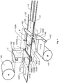
- the machine includes a conveyor line 110 configured to receive incoming body elements 120, for example between first and second receiving rolls 111 and 112 respectively, and moving the body elements 120 in a working direction F along a set of processing stations A, B, C and D respectively.
- Each processing station here has a particular function. For implementing reasons, however, some of these functions are integrated into one another, which is the reason why the volumes of the machine that correspond to the designations of the processing stations A, B, C and D partially overlap each other.
- a first processing station A contains laterally operating processing means configured to apply, by gluing, a first edge strip 121 along a first edge side of said four edge sides in such a manner that a primary side of the first edge strip 121 is brought to be parallel with the primary main side of the body element.
- the laterally operating processing means in the first processing station A preferably include at least one gluing device 131A and at least one first control roll 134A and at least one second control roll 134A, which control rolls are arranged to, while the body element 120 and the edge strip 121 attached thereto pass, apply a lateral pressure over the body element 120 and the first edge strip 121 across the working direction F of the conveyor line 110. This pressure fixates the first edge strip 121 at the body element 120.
- an inner measure between the control rolls 132A and 134A corresponds to a width dimension of a finished building board 120F. This is desirable because the building boards can be produced with very low tolerances and thereby also the risk of error propagation when mounting two or more building boards onto a supporting structure.
- Figure 2 illustrates how a first edge strip 121 is glued onto the body element 120 according to one embodiment of the invention.
- the edge strip 121 is gradually inserted parallel to the body element 120.
- a gluing device 131A is configured to apply glue via a nozzle 213A on at least one of the first edge side of the body element 120 and a side the first edge strip 121 which is directed towards the first edge side.
- the machine may also include a distance means arranged to accomplish a desired column between the edge strip 121 and the body element 120 to provide space for the nozzle 231A.
- a second processing station B includes vertically operating processing means 141B, 151B, 152C and 148B configured to apply a primary surface layer 140 on the building board.
- the primary surface layer 140 is applied by gluing, such that it covers the entire primary main side and the primary side of the first edge strip 121.
- the machine suitably includes a vertically operating processing means 141B, which is configured to, after gluing, apply the primary surface layer 140 on the body element 120 and the first edge strip 121 attached thereto in connection with the transport through the second processing station B.
- a required amount of glue is here applied on the body element 120 and the first edge strip 121 and/or the primary surface layer 140 via gluing means 148B.
- the primary surface layer 140 which for example can be in the form of a wall paper or fine meshed weave, is suitably stored on a roll 145 and can be provided to the second processing station B via one or more runners 142.
- a vertical pressure is applied over the body element 120 and the first edge strip 121 across the working direction F of the conveyor line 110 while the body element 120 and the first edge strip 121 pass through the second processing station B.
- the pressure is applied in such a manner that the primary side of the first edge strip 121 is brought in level with the primary main side when passing the second processing station B.
- the vertically operating processing means in the second processing station B comprising pressing rolls 151B and 152BC respectively, which are configured to engage against the primary and the secondary sides respectively of the body element 120.
- Both rolls 151B and 152BC have a rotation axis, which is essentially perpendicular to the working direction F of the conveyor line 110 and each roll 151B and 152BC preferably has a length exceeding a width of a finished building board 120F.
- FIGS 3 and 4 show how the pressing rolls 151B and 152BC may be arranged according to embodiments of the invention.
- a rotation axis 451 of a first pressing roll 151B is here rigidly attached to the machine and the first pressing roll suitably consists of a hard and relatively non-elastic material, such as steel.
- a second pressing roll 152BC is however radially flexible. This means that a distance between the periphery of the second pressing roll 152BC and the periphery of the first pressing roll 151B is adaptable to a thickness of an object which passes through the first and second pressing rolls 151B and 152BC, such as a body element 120 and any edge strips 121 and/or 122 attached thereto, a primary surface layer 140 and any secondary surface layer 160 (see below).
- the second pressing roll 152BC includes a core of a relatively hard material, such as steel.
- the core is covered by a resilient material 352, which is arranged to engage against the building boards when these pass between the first pressing roll 151B and the second pressing roll 152BC.
- the building boards here include a body element 120, at least one edge strip 121 and/or 122 and a primary surface layer 140. If a building board is provided with a secondary surface layer 160 it is preferable that this is applied in connection with the building board passing the pressing rolls 151B and 152BC.
- the resilient material may preferably be composed of textile, for example in the form of a carpet of suitable thickness.
- the second pressing roll 152BC includes a set of resilient discs 452, which are arranged along the rotation axis 455 of the second pressing roll 152BC.
- Each resilient disc 452 here has a segment width and an individually variable radius adaptable to the thickness of an object passing between the first pressing roll 151B and the disc 452.
- the second pressing roll 152BC is radially segment-wise flexible in units corresponding to the segment width of each disc 452.
- first pressing roll 151B and the second pressing roll 152BC may be the opposite, i.e. such that the first pressing roll 151B is on top, the second pressing roll 152BC is at the bottom and the building boards are transported with the primary side upwards through the machine.
- Such an arrangement is however generally less advantageous because then the pressing rolls 151B and 152 BC respectively also need to overcome gravity with respect to the weight of the building board.
- the laterally operating processing means 131A, 132A, 133AB and 134AB in the first processing station A are also configured to apply, by gluing, a second edge strip 122 along a second edge side of said edge sides of the building board 120.
- the second edge strip 122 is applied in a manner corresponding to what has been described above, i.e. such that a primary side of the secondary edge strip 122 is brought to be parallel with the primary main side of the body element 120.
- the vertically operating processing means 151B, 152BC and 148B in the second processing station B are therefore further configured to apply, by gluing, the primary surface layer 140 such that it covers the entire primary main side of the body element 120, the primary side of the first edge side 121 and the primary side of the second edge strip 122.
- a pressure is applied over the body element 120, the primary side of the first edge side 121 and the primary side of the second edge strip 122 across the working direction F of the conveyor line 110 while the body element 120, first edge side 121 and the second edge strip 122 pass the second processing station B in such a manner that both the primary side of the first edge strip 121 and the primary side of the second edge strip 122 are brought in parallel with the primary main side when passing the second processing station B.
- Figures 3 and 4 show an embodiment of the invention, where the first vertically pressing roll 151B, the second pressing roll 152BC and the laterally operating processing means 133AB are all located at essentially the same position at the conveyor line 110.
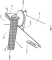
- Figure 5 shows another embodiment of the invention, where instead the vertically operating processing means act on the building board downstream of the point on the conveyor line 110 where the laterally operating processing means instead act against the edge strip 122 and the body element 120.
- a roll 530 represents a laterally operating processing means.
- the roll 530 also has a vertically steering function, and therefore shows different diameters along its central axis 520, so the edge strip 122 is steered to be applied against the body element 120 while these two elements are transported pass the roll 530 along the conveyor line 110.
- a lower segment 532 of the roll 530 has a diameter measure, which is adapted such that an upper ledge of the lower segment 532 can support the edge strip 122 as well as an outer edge of the body element 120.
- a mid segment 535AB of the roll 530 has a diameter measure, which is smaller than that of the lower segment 532 and is adapted so that at least one surface of the mid segment, which is essentially parallel with the central axis 520, engages at pressure against the edge strip 122 when this and the body element 120 are transported pass the roll 530.
- An upper segment 531 of the roll 530 has a diameter measure, which exceeds that of the mid segment 535AB and is adapted so that a lower ledge of the upper segment 531 steers the edge strip 122 in such a manner that the primary side of the edge strip 122 is brought in level with the primary main side of the body element 120.
- an assisting press wheel 550 is preferably arranged with a rotation axis essentially parallel with the working direction F and at a position of the conveyor line 110, such that the outer edge of the body element 120 is steered in on an adequate level relative to how the roll 530 steers the edge strip 122. It is further advantageous if the lower segment 532 is provided with a bevel 532B to facilitate steering in of a front edge of the body element 120 between the lower ledge of the upper segment 531 and above the upper ledge of the lower segment 532 when the body element 120 is fed forward against the roll 530 along the conveyor line 110.
- one or more surface layers are thereafter applied, by gluing, by vertically operating processing means according to what has been described above.
- the surface layer is applied such that it covers the entire primary main side of the body element 120 and the primary side of the edge strip 122.
- a vertical pressure is then applied over the body element 120 and the edge strip 120 across the working direction F of the conveyor line 110 while the body element 120 and the edge strip 122 pass this processing station in such a manner that the primary side of the edge strip 122 is finally brought in line with the primary main side with respect to both level and angle.
- Figure 1 also shows a roll 165, which stores a secondary surface layer 160.
- a third processing station C includes vertically operating processing means 152BC and 168C configured to, by gluing, apply a secondary surface layer 160, which covers the entire secondary main side of the body element 120 and a secondary side of the first edge strip 121 plus in case a second edge strip 122 has been applied, also a secondary side of the second edge strip 122.
- the secondary surface layer 160 which for example may be composed of a protecting and/or reinforcing weave, is suitably provided to the third processing station C via one or more runners 162.
- Gluing means 168C are suitably arranged to apply an adequate amount of glue on the body element 120 and the first edge strip 121 and/or on the secondary surface layer 160.
- Figure 3 shows how an applied surface layer 140 and/or 160, in a fourth processing station D, is cut according to an embodiment of the invention.
- at least one cutting means 171D (and 172D in Figure 1 ) is configured to, after application of the primary surface layer 140 on the primary main side of the body element 120 (and after application of a possible secondary surface layer 160 on the secondary main side), by cutting, adapt the surface layer 140 and/or 160 across the working direction F of the conveyor line 110, such that the extension of the surface layer matches the width of a finished building board 120F.
- Figure 3 shows a cutting means 171D placed above the building board, i.e. in connexion with the side which is covered by the secondary surface layer 160. However, it is most suitable to cut the primary surface layer 140 from the opposite main side of the building board (i.e. from below in Figure 3 ).
- the above-described functioning of the machine is preferably controlled by software/computer program in the form of a set of computer program instructions, which are stored in a memory unit in communicative connection with a control unit in the machine.
- a body element 120 in the form of a cuboid including a primary main side and a secondary main side opposite thereto each having a relatively large delimitation area and four edge sides with relatively small delimitation area
- a step 620 follows. Otherwise, the procedure loops back and stays in step 610.
- step 620 the conveyor line 110 moves the body element 120 in a working direction pass a set of processing stations. This movement takes place throughout the machine, which is symbolized by an arrow running in parallel with subsequent steps 630, 640 and 650 to a terminating step 660.
- a first edge strip 121 is applied, by gluing, along a first edge side of the body element 120 in such a manner that a primary side of the first edge strip 121 is brought to be parallel with the primary main side of the body element 120.
- a primary surface layer 140 is applied, by gluing, such that it covers the entire primary main side of the first edge strip 121.
- a vertical pressure is applied over the body element 120 and the first edge strip 121 across the working direction of the conveyor line 110 while the body element 120 and the first edge strip 121 are transported along the working direction of the conveyor line (110).
- the primary side of the first edge strip 121 is thereby brought in level with the primary main side of the body element 120.
- a finished building board is fed out from the machine, and the procedure loops back to step 610 to investigate if a new body element has been received.
- the steps described above with reference to Figure 6 may be controlled by means of a programmed computer apparatus.
- the embodiments of the invention described above with reference to the drawings comprise a computer apparatus and processes performed in a computer apparatus, the invention thus also extends to computer programs, particularly computer programs on or in a carrier, adapted for putting the invention into practice.
- the program may be in the form of source code, object code, a code intermediate source and object code such as in partially compiled form, or in any other form suitable for use in the implementation of the process according to the invention.
- the program may either be a part of an operating system, or be a separate application.
- the carrier may be any entity or device capable of carrying the program.
- the carrier may comprise a storage medium, such as a Flash memory, a ROM (Read Only Memory), for example a DVD (Digital Video/ Versatile Disk), a CD (Compact Disc) or a semiconductor ROM, an EPROM (Erasable Programmable Read-Only Memory), an EEPROM (Electrically Erasable Programmable Read-Only Memory), or a magnetic recording medium, for example a floppy disc or hard disc.
- the carrier may be a transmissible carrier such as an electrical or optical signal which may be conveyed via electrical or optical cable or by radio or by other means.
- the carrier may be constituted by such cable or device or means.
- the carrier may be an integrated circuit in which the program is embedded, the integrated circuit being adapted for performing, or for use in the performance of, the relevant processes.
Landscapes
- Engineering & Computer Science (AREA)
- Architecture (AREA)
- Structural Engineering (AREA)
- Civil Engineering (AREA)
- Mechanical Engineering (AREA)
- Manufacturing & Machinery (AREA)
- Fluid Mechanics (AREA)
- Physics & Mathematics (AREA)
- Chemical & Material Sciences (AREA)
- Ceramic Engineering (AREA)
- Finishing Walls (AREA)
- Orthopedics, Nursing, And Contraception (AREA)
- Automatic Assembly (AREA)
Priority Applications (1)
| Application Number | Priority Date | Filing Date | Title |
|---|---|---|---|
| PL13872425T PL2948602T3 (pl) | 2013-01-28 | 2013-11-28 | Maszyna i sposób wytwarzania płyty budowlanej |
Applications Claiming Priority (2)
| Application Number | Priority Date | Filing Date | Title |
|---|---|---|---|
| SE1350085A SE537025C2 (sv) | 2013-01-28 | 2013-01-28 | Maskin och tillverkningsmetod för byggskiva |
| PCT/SE2013/051409 WO2014116157A1 (en) | 2013-01-28 | 2013-11-28 | Machine and manufacturing method for building board |
Publications (3)
| Publication Number | Publication Date |
|---|---|
| EP2948602A1 EP2948602A1 (en) | 2015-12-02 |
| EP2948602A4 EP2948602A4 (en) | 2016-10-12 |
| EP2948602B1 true EP2948602B1 (en) | 2018-06-13 |
Family
ID=51227850
Family Applications (1)
| Application Number | Title | Priority Date | Filing Date |
|---|---|---|---|
| EP13872425.7A Not-in-force EP2948602B1 (en) | 2013-01-28 | 2013-11-28 | Machine and manufacturing method for building board |
Country Status (9)
| Country | Link |
|---|---|
| US (2) | US9694566B2 (pl) |
| EP (1) | EP2948602B1 (pl) |
| CN (1) | CN104956012B (pl) |
| DK (1) | DK2948602T3 (pl) |
| ES (1) | ES2687032T3 (pl) |
| PL (1) | PL2948602T3 (pl) |
| RU (1) | RU2637677C2 (pl) |
| SE (1) | SE537025C2 (pl) |
| WO (1) | WO2014116157A1 (pl) |
Families Citing this family (4)
| Publication number | Priority date | Publication date | Assignee | Title |
|---|---|---|---|---|
| SE537025C2 (sv) * | 2013-01-28 | 2014-12-09 | Oneday Wall Ab | Maskin och tillverkningsmetod för byggskiva |
| SE541590C2 (en) * | 2016-02-17 | 2019-11-12 | Oneday Wall Ab | Building Board Manufacturing |
| SE541674C2 (en) * | 2016-03-23 | 2019-11-26 | Ikea Supply Ag | Method and machine for forming a hollow board member |
| CN108340526A (zh) * | 2017-01-23 | 2018-07-31 | 上海联净复合材料技术有限公司 | 模块化发泡板的加工系统及方法 |
Family Cites Families (24)
| Publication number | Priority date | Publication date | Assignee | Title |
|---|---|---|---|---|
| FR1383005A (fr) * | 1963-10-16 | 1964-12-24 | Ferodo Sa | Carton ondulé notamment d'amiante revêtu d'aluminium et son procédé de fabrication |
| GB1159114A (en) * | 1966-01-24 | 1969-07-23 | Harris Lebus Ltd | Improvements in the Treatment of Wood Surfaces |
| GB1198393A (en) * | 1967-05-26 | 1970-07-15 | Hennecke G M B H Formerly Know | Apparatus for the continuous production of rigid plastics foam panels, in particular based on polyurethane, laminated with rigid convering layers |
| DE1729013B2 (de) * | 1967-10-16 | 1972-09-28 | Süllhöfer, Heinz, 4000 Düsseldorf | Verfahren und vorrichtung zur fortlaufenden herstellung von kaschierten platten aus polyurethan-hartschaumstoff |
| SE368847B (pl) * | 1972-06-09 | 1974-07-22 | Severoceske Papirny Np Steti | |
| SU854920A1 (ru) * | 1979-07-24 | 1981-08-15 | Специальное Конструкторское Бюро Научно-Производственного Объединения "Прокатдеталь" | Способ конвейерной отделки строительных изделий |
| DE3131183C2 (de) * | 1981-08-06 | 1984-07-19 | Held, Kurt, 7218 Trossingen | Verfahren und Vorrichtung zum Herstellen beschichteter Spanplattenprofile |
| US4581186A (en) * | 1982-12-17 | 1986-04-08 | Larson Roger E | Method of making foam core building panels in a continuous operation |
| SU1318412A1 (ru) * | 1985-05-22 | 1987-06-23 | Белорусский Научно-Исследовательский И Проектно-Технологический Институт Организации И Управления Строительством Госстроя Бсср | Лини дл отделки строительных панелей |
| EP0327261A1 (en) | 1988-01-30 | 1989-08-09 | Ecometal Limited | Building panels |
| DE3818540A1 (de) * | 1988-05-31 | 1989-12-07 | Rieter Werke Haendle | Walzwerk mit verstellbarem walzenspalt fuer keramische massen |
| US5545279A (en) * | 1992-12-30 | 1996-08-13 | Hall; Herbert L. | Method of making an insulation assembly |
| CA2146277C (en) * | 1994-05-25 | 2002-03-26 | John L. Phillips | Apparatus and method for manufacturing gypsum board |
| WO1997033056A1 (en) * | 1996-03-04 | 1997-09-12 | National Gypsum Company | Composite structural member |
| FR2746703B1 (fr) * | 1996-03-27 | 1998-04-24 | Cardo Door France | Procede et machine de fabrication de panneaux |
| DE19727129A1 (de) | 1997-06-26 | 1999-01-07 | Vaw Aluform System Technik Gmb | Verfahren zur Herstellung von geschäumten Dach- und Wandelementen und Vorrichtung zur Durchführung des Verfahrens |
| US5966885A (en) * | 1997-12-01 | 1999-10-19 | Chatelain; Paul J. | Foam panels for wall construction |
| DE10313055B4 (de) * | 2003-03-24 | 2006-12-28 | Homag Holzbearbeitungssysteme Ag | Verfahren und Vorrichtung zur Herstellung einer Leichtbauplatte |
| JP2005029334A (ja) * | 2003-07-11 | 2005-02-03 | Isetoo:Kk | 加圧シール装置 |
| US20090110920A1 (en) * | 2007-10-31 | 2009-04-30 | Robert Bordener | Laminate and frameless dry erase structure made therefrom |
| SE532999C2 (sv) | 2008-10-13 | 2010-06-08 | Peter Lindberg | Förfarande för framställning av byggskivor |
| DE102008052155A1 (de) * | 2008-10-20 | 2010-04-22 | Ficotec Veredelungs Gmbh | Verfahren zum Herstellen einer Trägerplatte und Trägerplatte |
| SE535477C2 (sv) | 2011-03-25 | 2012-08-21 | Lindberg Foervaltning Ab P | Väggskiva med kantlist och metod för framställning därav |
| SE537025C2 (sv) * | 2013-01-28 | 2014-12-09 | Oneday Wall Ab | Maskin och tillverkningsmetod för byggskiva |
-
2013
- 2013-01-28 SE SE1350085A patent/SE537025C2/sv not_active IP Right Cessation
- 2013-11-28 CN CN201380071666.XA patent/CN104956012B/zh not_active Expired - Fee Related
- 2013-11-28 ES ES13872425.7T patent/ES2687032T3/es active Active
- 2013-11-28 RU RU2015136473A patent/RU2637677C2/ru not_active IP Right Cessation
- 2013-11-28 DK DK13872425.7T patent/DK2948602T3/en active
- 2013-11-28 US US14/761,875 patent/US9694566B2/en not_active Expired - Fee Related
- 2013-11-28 PL PL13872425T patent/PL2948602T3/pl unknown
- 2013-11-28 EP EP13872425.7A patent/EP2948602B1/en not_active Not-in-force
- 2013-11-28 WO PCT/SE2013/051409 patent/WO2014116157A1/en not_active Ceased
-
2017
- 2017-04-28 US US15/581,840 patent/US10189234B2/en not_active Expired - Fee Related
Non-Patent Citations (1)
| Title |
|---|
| None * |
Also Published As
| Publication number | Publication date |
|---|---|
| ES2687032T3 (es) | 2018-10-23 |
| US9694566B2 (en) | 2017-07-04 |
| SE1350085A1 (sv) | 2014-07-29 |
| EP2948602A1 (en) | 2015-12-02 |
| RU2637677C2 (ru) | 2017-12-06 |
| CN104956012B (zh) | 2019-08-20 |
| PL2948602T3 (pl) | 2018-11-30 |
| CN104956012A (zh) | 2015-09-30 |
| SE537025C2 (sv) | 2014-12-09 |
| WO2014116157A1 (en) | 2014-07-31 |
| US10189234B2 (en) | 2019-01-29 |
| US20170232723A1 (en) | 2017-08-17 |
| DK2948602T3 (en) | 2018-09-10 |
| EP2948602A4 (en) | 2016-10-12 |
| RU2015136473A (ru) | 2017-03-06 |
| US20150360456A1 (en) | 2015-12-17 |
Similar Documents
| Publication | Publication Date | Title |
|---|---|---|
| US10189234B2 (en) | Machine and manufacturing method for building board | |
| KR102197543B1 (ko) | 플로어 패널용 기계적 잠금 시스템 | |
| EP2627503B1 (en) | Method of continuous manufacture of a composite hollow board material, and machine and computer program | |
| EP2089196B1 (en) | Method for manufacturing bamboo mats | |
| EP2909032B1 (en) | Method and apparatus for making double panels | |
| US6128864A (en) | Elliptical arch | |
| WO2015030654A1 (en) | A method for producing a lamella core | |
| US20170203548A1 (en) | Skirting board, decorative system and method for manufacturing a skirting board | |
| CN1131361C (zh) | 用于连续制作带有矿物填料的轻型建筑面板的方法和设备 | |
| CN105058858A (zh) | 高速全自动胶盒粘盒机 | |
| KR20160131286A (ko) | 복층유리 제조용 간봉 공급장치 | |
| KR20120002693U (ko) | 프로파일 랩핑장치 | |
| CN102187039A (zh) | 建筑板的制造方法 | |
| EP2756939A1 (en) | Edge banding machine | |
| EP2247432A1 (en) | Method and apparatus for manufacturing coated profile members | |
| US8850777B2 (en) | Wall board with edge strip and method for production thereof | |
| CN111093964B (zh) | 用于生产纤维面板形建筑元件的方法和设备 | |
| KR200332631Y1 (ko) | 라미네이팅 패널의 측부 마감장치 | |
| JP2006307590A (ja) | 曲線階段の施工方法 | |
| RU2824867C1 (ru) | Способ изготовления согнутой панели и согнутая панель | |
| JP6452316B2 (ja) | 三次元用建築板材の成形装置及びその成形方法 | |
| CN207901372U (zh) | 烘边机窄板稳定机构 | |
| US3695966A (en) | Method of manufacturing furniture fabrication cores | |
| CN103586318A (zh) | 卷闸门压膜成型机 | |
| KR19980063011A (ko) | 래핑(wrapping)목의 접착방법 |
Legal Events
| Date | Code | Title | Description |
|---|---|---|---|
| PUAI | Public reference made under article 153(3) epc to a published international application that has entered the european phase |
Free format text: ORIGINAL CODE: 0009012 |
|
| 17P | Request for examination filed |
Effective date: 20150819 |
|
| AK | Designated contracting states |
Kind code of ref document: A1 Designated state(s): AL AT BE BG CH CY CZ DE DK EE ES FI FR GB GR HR HU IE IS IT LI LT LU LV MC MK MT NL NO PL PT RO RS SE SI SK SM TR |
|
| AX | Request for extension of the european patent |
Extension state: BA ME |
|
| DAX | Request for extension of the european patent (deleted) | ||
| A4 | Supplementary search report drawn up and despatched |
Effective date: 20160912 |
|
| RIC1 | Information provided on ipc code assigned before grant |
Ipc: E04C 2/26 20060101AFI20160906BHEP Ipc: B30B 3/02 20060101ALI20160906BHEP Ipc: B32B 37/22 20060101ALI20160906BHEP Ipc: B29C 63/00 20060101ALI20160906BHEP |
|
| STAA | Information on the status of an ep patent application or granted ep patent |
Free format text: STATUS: EXAMINATION IS IN PROGRESS |
|
| 17Q | First examination report despatched |
Effective date: 20170810 |
|
| GRAP | Despatch of communication of intention to grant a patent |
Free format text: ORIGINAL CODE: EPIDOSNIGR1 |
|
| STAA | Information on the status of an ep patent application or granted ep patent |
Free format text: STATUS: GRANT OF PATENT IS INTENDED |
|
| INTG | Intention to grant announced |
Effective date: 20180201 |
|
| GRAS | Grant fee paid |
Free format text: ORIGINAL CODE: EPIDOSNIGR3 |
|
| GRAA | (expected) grant |
Free format text: ORIGINAL CODE: 0009210 |
|
| STAA | Information on the status of an ep patent application or granted ep patent |
Free format text: STATUS: THE PATENT HAS BEEN GRANTED |
|
| AK | Designated contracting states |
Kind code of ref document: B1 Designated state(s): AL AT BE BG CH CY CZ DE DK EE ES FI FR GB GR HR HU IE IS IT LI LT LU LV MC MK MT NL NO PL PT RO RS SE SI SK SM TR |
|
| REG | Reference to a national code |
Ref country code: GB Ref legal event code: FG4D |
|
| REG | Reference to a national code |
Ref country code: CH Ref legal event code: EP Ref country code: AT Ref legal event code: REF Ref document number: 1008670 Country of ref document: AT Kind code of ref document: T Effective date: 20180615 |
|
| REG | Reference to a national code |
Ref country code: IE Ref legal event code: FG4D |
|
| REG | Reference to a national code |
Ref country code: DE Ref legal event code: R096 Ref document number: 602013039053 Country of ref document: DE |
|
| REG | Reference to a national code |
Ref country code: CH Ref legal event code: NV Representative=s name: ING. MARCO ZARDI C/O M. ZARDI AND CO. S.A., CH |
|
| REG | Reference to a national code |
Ref country code: DK Ref legal event code: T3 Effective date: 20180905 |
|
| REG | Reference to a national code |
Ref country code: NL Ref legal event code: FP |
|
| REG | Reference to a national code |
Ref country code: NO Ref legal event code: T2 Effective date: 20180613 |
|
| REG | Reference to a national code |
Ref country code: EE Ref legal event code: FG4A Ref document number: E015953 Country of ref document: EE Effective date: 20180828 |
|
| REG | Reference to a national code |
Ref country code: ES Ref legal event code: FG2A Ref document number: 2687032 Country of ref document: ES Kind code of ref document: T3 Effective date: 20181023 |
|
| REG | Reference to a national code |
Ref country code: LT Ref legal event code: MG4D |
|
| PG25 | Lapsed in a contracting state [announced via postgrant information from national office to epo] |
Ref country code: CY Free format text: LAPSE BECAUSE OF FAILURE TO SUBMIT A TRANSLATION OF THE DESCRIPTION OR TO PAY THE FEE WITHIN THE PRESCRIBED TIME-LIMIT Effective date: 20180613 Ref country code: SE Free format text: LAPSE BECAUSE OF FAILURE TO SUBMIT A TRANSLATION OF THE DESCRIPTION OR TO PAY THE FEE WITHIN THE PRESCRIBED TIME-LIMIT Effective date: 20180613 Ref country code: BG Free format text: LAPSE BECAUSE OF FAILURE TO SUBMIT A TRANSLATION OF THE DESCRIPTION OR TO PAY THE FEE WITHIN THE PRESCRIBED TIME-LIMIT Effective date: 20180913 Ref country code: LT Free format text: LAPSE BECAUSE OF FAILURE TO SUBMIT A TRANSLATION OF THE DESCRIPTION OR TO PAY THE FEE WITHIN THE PRESCRIBED TIME-LIMIT Effective date: 20180613 |
|
| PG25 | Lapsed in a contracting state [announced via postgrant information from national office to epo] |
Ref country code: LV Free format text: LAPSE BECAUSE OF FAILURE TO SUBMIT A TRANSLATION OF THE DESCRIPTION OR TO PAY THE FEE WITHIN THE PRESCRIBED TIME-LIMIT Effective date: 20180613 Ref country code: HR Free format text: LAPSE BECAUSE OF FAILURE TO SUBMIT A TRANSLATION OF THE DESCRIPTION OR TO PAY THE FEE WITHIN THE PRESCRIBED TIME-LIMIT Effective date: 20180613 Ref country code: GR Free format text: LAPSE BECAUSE OF FAILURE TO SUBMIT A TRANSLATION OF THE DESCRIPTION OR TO PAY THE FEE WITHIN THE PRESCRIBED TIME-LIMIT Effective date: 20180914 Ref country code: RS Free format text: LAPSE BECAUSE OF FAILURE TO SUBMIT A TRANSLATION OF THE DESCRIPTION OR TO PAY THE FEE WITHIN THE PRESCRIBED TIME-LIMIT Effective date: 20180613 |
|
| PGFP | Annual fee paid to national office [announced via postgrant information from national office to epo] |
Ref country code: NL Payment date: 20181116 Year of fee payment: 6 |
|
| PG25 | Lapsed in a contracting state [announced via postgrant information from national office to epo] |
Ref country code: IS Free format text: LAPSE BECAUSE OF FAILURE TO SUBMIT A TRANSLATION OF THE DESCRIPTION OR TO PAY THE FEE WITHIN THE PRESCRIBED TIME-LIMIT Effective date: 20181013 Ref country code: RO Free format text: LAPSE BECAUSE OF FAILURE TO SUBMIT A TRANSLATION OF THE DESCRIPTION OR TO PAY THE FEE WITHIN THE PRESCRIBED TIME-LIMIT Effective date: 20180613 Ref country code: SK Free format text: LAPSE BECAUSE OF FAILURE TO SUBMIT A TRANSLATION OF THE DESCRIPTION OR TO PAY THE FEE WITHIN THE PRESCRIBED TIME-LIMIT Effective date: 20180613 |
|
| PGFP | Annual fee paid to national office [announced via postgrant information from national office to epo] |
Ref country code: NO Payment date: 20181119 Year of fee payment: 6 Ref country code: DK Payment date: 20181116 Year of fee payment: 6 Ref country code: DE Payment date: 20181119 Year of fee payment: 6 Ref country code: FI Payment date: 20181120 Year of fee payment: 6 |
|
| PG25 | Lapsed in a contracting state [announced via postgrant information from national office to epo] |
Ref country code: SM Free format text: LAPSE BECAUSE OF FAILURE TO SUBMIT A TRANSLATION OF THE DESCRIPTION OR TO PAY THE FEE WITHIN THE PRESCRIBED TIME-LIMIT Effective date: 20180613 |
|
| PGFP | Annual fee paid to national office [announced via postgrant information from national office to epo] |
Ref country code: ES Payment date: 20181203 Year of fee payment: 12 Ref country code: BE Payment date: 20181116 Year of fee payment: 6 Ref country code: IT Payment date: 20181123 Year of fee payment: 6 Ref country code: GB Payment date: 20181116 Year of fee payment: 6 Ref country code: CH Payment date: 20181119 Year of fee payment: 6 Ref country code: FR Payment date: 20181121 Year of fee payment: 6 |
|
| REG | Reference to a national code |
Ref country code: DE Ref legal event code: R097 Ref document number: 602013039053 Country of ref document: DE |
|
| PLBE | No opposition filed within time limit |
Free format text: ORIGINAL CODE: 0009261 |
|
| STAA | Information on the status of an ep patent application or granted ep patent |
Free format text: STATUS: NO OPPOSITION FILED WITHIN TIME LIMIT |
|
| 26N | No opposition filed |
Effective date: 20190314 |
|
| PG25 | Lapsed in a contracting state [announced via postgrant information from national office to epo] |
Ref country code: SI Free format text: LAPSE BECAUSE OF FAILURE TO SUBMIT A TRANSLATION OF THE DESCRIPTION OR TO PAY THE FEE WITHIN THE PRESCRIBED TIME-LIMIT Effective date: 20180613 |
|
| PG25 | Lapsed in a contracting state [announced via postgrant information from national office to epo] |
Ref country code: LU Free format text: LAPSE BECAUSE OF NON-PAYMENT OF DUE FEES Effective date: 20181128 Ref country code: MC Free format text: LAPSE BECAUSE OF FAILURE TO SUBMIT A TRANSLATION OF THE DESCRIPTION OR TO PAY THE FEE WITHIN THE PRESCRIBED TIME-LIMIT Effective date: 20180613 |
|
| REG | Reference to a national code |
Ref country code: IE Ref legal event code: MM4A |
|
| PG25 | Lapsed in a contracting state [announced via postgrant information from national office to epo] |
Ref country code: IE Free format text: LAPSE BECAUSE OF NON-PAYMENT OF DUE FEES Effective date: 20181128 |
|
| PG25 | Lapsed in a contracting state [announced via postgrant information from national office to epo] |
Ref country code: AL Free format text: LAPSE BECAUSE OF FAILURE TO SUBMIT A TRANSLATION OF THE DESCRIPTION OR TO PAY THE FEE WITHIN THE PRESCRIBED TIME-LIMIT Effective date: 20180613 |
|
| PG25 | Lapsed in a contracting state [announced via postgrant information from national office to epo] |
Ref country code: MT Free format text: LAPSE BECAUSE OF NON-PAYMENT OF DUE FEES Effective date: 20181128 |
|
| PGFP | Annual fee paid to national office [announced via postgrant information from national office to epo] |
Ref country code: CZ Payment date: 20191030 Year of fee payment: 7 |
|
| PGFP | Annual fee paid to national office [announced via postgrant information from national office to epo] |
Ref country code: PL Payment date: 20191029 Year of fee payment: 7 |
|
| PGFP | Annual fee paid to national office [announced via postgrant information from national office to epo] |
Ref country code: TR Payment date: 20191101 Year of fee payment: 7 |
|
| PG25 | Lapsed in a contracting state [announced via postgrant information from national office to epo] |
Ref country code: PT Free format text: LAPSE BECAUSE OF FAILURE TO SUBMIT A TRANSLATION OF THE DESCRIPTION OR TO PAY THE FEE WITHIN THE PRESCRIBED TIME-LIMIT Effective date: 20180613 |
|
| REG | Reference to a national code |
Ref country code: DE Ref legal event code: R119 Ref document number: 602013039053 Country of ref document: DE |
|
| REG | Reference to a national code |
Ref country code: FI Ref legal event code: MAE |
|
| REG | Reference to a national code |
Ref country code: EE Ref legal event code: MM4A Ref document number: E015953 Country of ref document: EE Effective date: 20191130 |
|
| REG | Reference to a national code |
Ref country code: DK Ref legal event code: EBP Effective date: 20191130 Ref country code: NO Ref legal event code: MMEP |
|
| PG25 | Lapsed in a contracting state [announced via postgrant information from national office to epo] |
Ref country code: HU Free format text: LAPSE BECAUSE OF FAILURE TO SUBMIT A TRANSLATION OF THE DESCRIPTION OR TO PAY THE FEE WITHIN THE PRESCRIBED TIME-LIMIT; INVALID AB INITIO Effective date: 20131128 Ref country code: MK Free format text: LAPSE BECAUSE OF NON-PAYMENT OF DUE FEES Effective date: 20180613 |
|
| REG | Reference to a national code |
Ref country code: CH Ref legal event code: PL |
|
| REG | Reference to a national code |
Ref country code: NL Ref legal event code: MM Effective date: 20191201 |
|
| PG25 | Lapsed in a contracting state [announced via postgrant information from national office to epo] |
Ref country code: NO Free format text: LAPSE BECAUSE OF NON-PAYMENT OF DUE FEES Effective date: 20191130 Ref country code: EE Free format text: LAPSE BECAUSE OF NON-PAYMENT OF DUE FEES Effective date: 20191130 Ref country code: CH Free format text: LAPSE BECAUSE OF NON-PAYMENT OF DUE FEES Effective date: 20191130 Ref country code: LI Free format text: LAPSE BECAUSE OF NON-PAYMENT OF DUE FEES Effective date: 20191130 Ref country code: FI Free format text: LAPSE BECAUSE OF NON-PAYMENT OF DUE FEES Effective date: 20191128 |
|
| REG | Reference to a national code |
Ref country code: AT Ref legal event code: MM01 Ref document number: 1008670 Country of ref document: AT Kind code of ref document: T Effective date: 20191128 |
|
| REG | Reference to a national code |
Ref country code: BE Ref legal event code: MM Effective date: 20191130 |
|
| GBPC | Gb: european patent ceased through non-payment of renewal fee |
Effective date: 20191128 |
|
| PG25 | Lapsed in a contracting state [announced via postgrant information from national office to epo] |
Ref country code: NL Free format text: LAPSE BECAUSE OF NON-PAYMENT OF DUE FEES Effective date: 20191201 |
|
| REG | Reference to a national code |
Ref country code: AT Ref legal event code: UEP Ref document number: 1008670 Country of ref document: AT Kind code of ref document: T Effective date: 20180613 |
|
| PG25 | Lapsed in a contracting state [announced via postgrant information from national office to epo] |
Ref country code: FR Free format text: LAPSE BECAUSE OF NON-PAYMENT OF DUE FEES Effective date: 20191130 Ref country code: DE Free format text: LAPSE BECAUSE OF NON-PAYMENT OF DUE FEES Effective date: 20200603 Ref country code: IT Free format text: LAPSE BECAUSE OF NON-PAYMENT OF DUE FEES Effective date: 20191128 Ref country code: DK Free format text: LAPSE BECAUSE OF NON-PAYMENT OF DUE FEES Effective date: 20191130 Ref country code: GB Free format text: LAPSE BECAUSE OF NON-PAYMENT OF DUE FEES Effective date: 20191128 |
|
| PG25 | Lapsed in a contracting state [announced via postgrant information from national office to epo] |
Ref country code: BE Free format text: LAPSE BECAUSE OF NON-PAYMENT OF DUE FEES Effective date: 20191130 Ref country code: AT Free format text: LAPSE BECAUSE OF NON-PAYMENT OF DUE FEES Effective date: 20191128 |
|
| REG | Reference to a national code |
Ref country code: ES Ref legal event code: FD2A Effective date: 20210601 |
|
| PG25 | Lapsed in a contracting state [announced via postgrant information from national office to epo] |
Ref country code: CZ Free format text: LAPSE BECAUSE OF NON-PAYMENT OF DUE FEES Effective date: 20201128 |
|
| PG25 | Lapsed in a contracting state [announced via postgrant information from national office to epo] |
Ref country code: ES Free format text: LAPSE BECAUSE OF NON-PAYMENT OF DUE FEES Effective date: 20191129 |
|
| PG25 | Lapsed in a contracting state [announced via postgrant information from national office to epo] |
Ref country code: TR Free format text: LAPSE BECAUSE OF NON-PAYMENT OF DUE FEES Effective date: 20201128 |
|
| PG25 | Lapsed in a contracting state [announced via postgrant information from national office to epo] |
Ref country code: PL Free format text: LAPSE BECAUSE OF NON-PAYMENT OF DUE FEES Effective date: 20201128 |