EP2947731A1 - Zündkerze - Google Patents
Zündkerze Download PDFInfo
- Publication number
- EP2947731A1 EP2947731A1 EP15168244.0A EP15168244A EP2947731A1 EP 2947731 A1 EP2947731 A1 EP 2947731A1 EP 15168244 A EP15168244 A EP 15168244A EP 2947731 A1 EP2947731 A1 EP 2947731A1
- Authority
- EP
- European Patent Office
- Prior art keywords
- ground electrode
- hardness
- base end
- distance
- distal end
- Prior art date
- Legal status (The legal status is an assumption and is not a legal conclusion. Google has not performed a legal analysis and makes no representation as to the accuracy of the status listed.)
- Granted
Links
Images





Classifications
-
- H—ELECTRICITY
- H01—ELECTRIC ELEMENTS
- H01T—SPARK GAPS; OVERVOLTAGE ARRESTERS USING SPARK GAPS; SPARKING PLUGS; CORONA DEVICES; GENERATING IONS TO BE INTRODUCED INTO NON-ENCLOSED GASES
- H01T13/00—Sparking plugs
- H01T13/20—Sparking plugs characterised by features of the electrodes or insulation
- H01T13/32—Sparking plugs characterised by features of the electrodes or insulation characterised by features of the earthed electrode
-
- H—ELECTRICITY
- H01—ELECTRIC ELEMENTS
- H01T—SPARK GAPS; OVERVOLTAGE ARRESTERS USING SPARK GAPS; SPARKING PLUGS; CORONA DEVICES; GENERATING IONS TO BE INTRODUCED INTO NON-ENCLOSED GASES
- H01T21/00—Apparatus or processes specially adapted for the manufacture or maintenance of spark gaps or sparking plugs
- H01T21/02—Apparatus or processes specially adapted for the manufacture or maintenance of spark gaps or sparking plugs of sparking plugs
-
- H—ELECTRICITY
- H01—ELECTRIC ELEMENTS
- H01T—SPARK GAPS; OVERVOLTAGE ARRESTERS USING SPARK GAPS; SPARKING PLUGS; CORONA DEVICES; GENERATING IONS TO BE INTRODUCED INTO NON-ENCLOSED GASES
- H01T13/00—Sparking plugs
- H01T13/20—Sparking plugs characterised by features of the electrodes or insulation
- H01T13/39—Selection of materials for electrodes
Definitions
- This disclosure relates to a spark plug.
- a spark plug in general, includes a center electrode and a ground electrode that are disposed at a distal end side of the spark plug.
- the center electrode projects from a distal end of an insulator an is held in an axial hole of the insulator.
- the ground electrode is joined to a distal end portion of a metal shell.
- JP-A-2013-222676 discloses a technique that enhances the breakage resistance of the ground electrode by disposing a large width portion at a portion of the ground electrode.
- JP-A-2013-012462 discloses a technique that enhances the breakage resistance of the ground electrode by adjusting the thickness of the ground electrode in the radial direction.
- JP-A-2012-160351 discloses a technique that enhances the breakage resistance of the ground electrode by disposing a depressed portion at a back surface or a side surface of a bending portion of the ground electrode, and increasing the hardness of a bottom of the depressed portion.
- JP-A-2010-80059 discloses a technique that enhances the breakage resistance of the ground electrode by disposing a needle-shaped electrode tip in the ground electrode.
- a spark plug includes: a pipe-shaped insulator having an axial hole that passes through the insulator in an axial direction; a center electrode projecting from a distal end of the insulator; a metal shell covering a peripheral portion of the insulator; and a ground electrode whose base end portion is joined to a distal end portion of the metal shell, the ground electrode having a bent portion that is bent such that a distal end portion of the ground electrode is disposed with being spaced from a distal end portion of the center electrode.
- a hardness distribution is obtained by cutting the ground electrode from a distal end to a base end of the ground electrode at a cutting plane including an axial line of the spark plug and passing through a center of the ground electrode, and then measuring hardness of the ground electrode at a plurality of positions disposed with a distance from the base end of the ground electrode along a center line of the cutting plane of the ground electrode, the distance increasing in increments of 0.1 mm.
- n is a natural number.
- a portion of the ground electrode from a position at a distance of 0.1 mm from the base end along the center line to the distal end is categorizable into a high hardness portion and a low hardness portion using the hardness distribution, the high hardness portion being a portion from the position at a distance of 0.1 mm from the base end along the center line to a position at a distance of 0.1 ⁇ n (mm) from the base end along the center line, the low hardness portion being a portion from a position at a distance of 0.1 ⁇ (n + 1) (mm) from the base end along the center line to the distal end.
- the low hardness portion includes a portion that has a largest curvature in the ground electrode. A highest hardness of the low hardness portion is lower than a lowest hardness of the high hardness portion.
- the position at a distance of 0.1 mm from the base end is equivalent to a position at the most base end side of the high hardness portion.
- the position at a distance of 0.1 ⁇ n (mm) from the base end is equivalent to a position at the most distal end side of the high hardness portion.
- the technique of this disclosure can be realized in various embodiments.
- the technique according to this disclosure can be realized, for example, in the form of a method for fabricating a spark plug, or a method for fabricating a metal shell for the spark plug.
- Fig. 1 is a front view illustrating a spark plug 100 according to one embodiment of this disclosure.
- the lower side, where a firing end of the spark plug 100 is disposed is defined as a distal end 30e side of the spark plug 100
- the upper side is defined as a rear end side of the spark plug 100.
- the spark plug 100 includes an insulator 10, a center electrode 20, a ground electrode 30, a terminal metal fitting 40 and, a metal shell 50.
- the insulator 10 includes an axial hole extending along an axial line O. Note that the axial line O is also referred to as a central axis.
- the center electrode 20 is a rod-shaped electrode extending along the axial line O.
- the center electrode 20 is held by the insulator 10 and is inserted into the axial hole of the insulator 10.
- One end of the ground electrode 30 is fixed to a distal end portion 52 of the metal shell 50.
- the other end of the ground electrode 30 is opposed to the center electrode 20.
- the terminal metal fitting 40 is a terminal nut for receiving electric power supply, and is electrically connected to the center electrode 20.
- the metal shell 50 is a pipe-shaped member covering a peripheral portion of the insulator 10.
- the insulator 10 is fixed in the metal shell 50.
- a thread portion 54 is formed at an outer peripheral portion of the metal shell 50.
- the thread portion 54 is a portion where a thread ridge is formed.
- the thread portion 54 is threadably mounted in a thread hole of an engine head when the spark plug 100 is mounted to the engine head.
- Figs. 2A to 2I illustrate a part of fabrication processes of the spark plug according to one embodiment.
- Fig. 2A illustrates a process for preparing the metal shell 50 before the ground electrode 30 is joined (or mounted) to the metal shell 50.
- Fig. 2B illustrates a joining process for joining a linearly extending rod-shaped ground electrode member 30p to the distal end portion 52 of the metal shell 50 with upright position. Note that the upright position of the ground electrode member 30p means a state in which the ground electrode member 30p is in a direction parallel to the axial line O ( Fig. 1 ) of the metal shell 50.
- This joining process is carried out using, for example, resistance welding.
- FIG. 2C illustrates a process for inclining the ground electrode member 30p using a push jig 300 and an auxiliary jig 320.
- This process is equivalent to a first manufacturing process of bending processes for bending the ground electrode member 30p.
- a side surface 310 of the push jig 300 is a planar surface that is inclined with respect to the central axis of the metal shell 50 with or at a predetermined angle.
- the push jig 300 for example, moves from the distal end side (the upper side in the drawing) toward the rear end side (the lower side in the drawing) in the central axial direction of the metal shell 50 while the auxiliary jig 320 supports the outside portion of the ground electrode member 30p.
- Fig. 2D illustrates a state in which the ground electrode member 30p is inclined while being joined to the metal shell 50.
- Fig. 2E illustrates a manufacturing process for making upright the ground electrode member 30p again using a push jig 400 and an auxiliary jig 420.
- This process is equivalent to a second manufacturing process of the bending processes for bending the ground electrode member 30p.
- the push jig 400 moves from the outside of the metal shell 50 toward the inside of the metal shell 50 while the auxiliary jig 420 supports the inside portion of the ground electrode member 30p. This can make upright the ground electrode member 30p.
- the auxiliary jig 420 may not be necessarily used.
- Fig. 2F illustrates a state in which the ground electrode member 30p stands in the upright position again and is joined to the metal shell 50.
- Fig. 2G illustrates a crimping process.
- the insulator 10 in which the center electrode 20 is assembled is inserted into the metal shell 50. Furthermore, the insulator 10 is fixed to the metal shell 50 by crimping a crimped portion (not illustrated) at the rear end of the metal shell 50.
- Fig. 2H illustrates a bending process for bending the ground electrode member 30p to make a final bending shape using a push jig 500 and an auxiliary jig 520.
- This process is equivalent to a third manufacturing process of the bending processes for bending the ground electrode member 30p.
- the push jig 500 moves from the distal end side (the upper side in the drawing) toward the rear end side (the lower side in the drawing) of the metal shell 50 while the auxiliary jig 520 supports the inside portion of the ground electrode member 30p. This can bend the ground electrode member 30p to make a final shape of the ground electrode 30.
- the auxiliary jig 520 may not be necessarily used.
- FIG. 2I illustrates the ground electrode 30 having a bent portion 30b that is obtained by bending the ground electrode member 30p.
- the bent portion 30b is a portion that has the largest curvature in the ground electrode 30.
- the rod-shaped ground electrode member 30p may be bent in one step.
- the rod-shaped ground electrode member 30p may be bent in two steps, which are pre-bending step and final bending step.
- the hardness of the high hardness portion (described below) of the ground electrode 30 can be increased by bending the ground electrode member 30p in the manufacturing processes described with reference to Figs. 2A to 2I . Consequently, the breakage resistance of the ground electrode 30 can be enhanced.
- the first manufacturing process illustrated in Fig. 2C as the inclined angle of the ground electrode member 30p increases, the hardness of the high hardness portion of the final ground electrode 30 can be higher.
- the range of the high hardness portion can be controlled by adjusting the height (a position along the axial line O of the spark plug) of the auxiliary jig 320 illustrated in Fig. 2C and/or the height of the auxiliary jig 420 illustrated in Fig. 2E .
- the range of the high hardness portion can be larger, for example, by placing the height of the auxiliary jig 320 upper in Fig. 2C . As a result, the high hardness portion can be extended toward the more distal end side of the ground electrode 30.
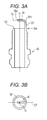
- FIGs. 3A and 3B are explanatory views illustrating a cutting plane used for measuring the hardness of the ground electrode 30.
- a cutting plane CP of the ground electrode 30 is a surface obtained by cutting the ground electrode 30 along a surface that includes the axial line O of the spark plug with passing through the center of the ground electrode 30.
- the hardness measurement test a portion from the distal end 30e to a base end 30s of the ground electrode 30 is cut along the cutting plane CP.
- the hardness of the ground electrode 30 is measured at positions in increments of 0.1 mm along a center line CL of the cutting plane CP of the ground electrode 30.
- the center line CL of the cutting plane CP means a line that extends through the center of the cutting plane CP of the ground electrode 30.
- the hardness measurement test is carried out in accordance with the Micro Vickers hardness test that is specified in Japanese Industrial Standard Z2244. In the test, test force is 980.7 mN, holding time is 15 seconds, and indenter approach speed is 60 ⁇ m
- Fig. 4 is a graph illustrating a hardness distribution obtained by the hardness measurement test for various kinds of samples.
- the horizontal axis indicates a distance from a joining surface between the ground electrode 30 and the metal shell 50 to a measuring position, while the vertical axis indicates the hardness.
- a position of the joining surface between the ground electrode 30 and the metal shell 50 is equivalent to a position of the base end 30s ( Figs. 3A and 3B ) of the ground electrode 30.
- a position at a distance of 10 mm from the joining surface is approximately equal to the distal end 30e ( Figs. 3A and 3B ) of the ground electrode 30.
- Fig. 4 illustrates the hardness distributions for four types of samples SP01 to SP03 and SP10.
- the samples SP01 to SP03 are samples in which the hardness of the ground electrode 30 is increased by the processes illustrated in Figs. 2A to 2I .
- the sample SP10 is a sample as a comparative example that is fabricated without the first manufacturing process and the second manufacturing process illustrated in Figs. 2C to 2F .
- the hardness distribution of the ground electrode 30 is categorizable into a high hardness portion HHP and a low hardness portion LHP.
- the high hardness portion HHP exists near the base end 30s of the ground electrode 30, while the low hardness portion LHP exists at the distal end side of the ground electrode 30 from the high hardness portion HHP.
- the high hardness portion HHP is a portion that has the hardness higher than that of the low hardness portion LHP. Namely, the lowest hardness of the high hardness portion HHP is higher than the highest hardness of the low hardness portion LHP. The following is the reason why the high hardness portion HHP is formed. A portion equivalent to the high hardness portion HHP is bent in the first manufacturing process and the second manufacturing process illustrated in Figs. 2C to 2F . Thus, the hardness of the portion equivalent to the high hardness portion HHP is increased by the work hardening of the high hardness portion HHP.
- the hardness is measured at the positions along the center line CL, the positions being spaced in increments of 0.1 mm. Therefore, the high hardness portion HHP extends from a position at a distance of 0.1 mm from the base end 30s of the ground electrode 30 to a position at a distance of 0.1 ⁇ n (mm) from the base end 30s, wherein "n" is an arbitrary natural number. While, the low hardness portion LHP extends from a position at a distance of 0.1 ⁇ (n + 1) (mm) from the base end 30s of the ground electrode 30 to the distal end 30e of the ground electrode 30. As described later, it is preferred that "n" is equal to or more than 30 (namely, the high hardness portion HHP extends to a position at a distance of 3 mm from the base end 30s).
- the high hardness portion HHP of the ground electrode 30 has a function that enhances the breakage resistance of the ground electrode 30.
- the low hardness portion LHP has a function that maintains or enhances the bending workability thereof during the bending process (the third manufacturing process in Fig. 2H ) for forming the bent portion 30b.
- the ground electrode 30 is relatively breakable at a portion close to the base end 30s. Therefore, this portion can be changed to the high hardness portion HHP to enhance the breakage resistance thereof.
- a portion at the distal end side from the high hardness portion HHP can be changed to the low hardness portion LHP to maintain or enhance the bending workability thereof.
- the hardness of the high hardness portions HHP of the three kinds of samples SP01 to SP03 are different from one another.
- the inclined angles of the ground electrode members 30p of the three kinds of samples SP01 to SP03 bent in the first manufacturing process of Fig. 2C are different from one another. Accordingly, each sample has different degree of work hardening.
- the hardness of the high hardness portion HHP can be higher.
- a portion showing the highest hardness of the low hardness portion LHP exists in the bent portion 30b ( Figs. 3A and 3B ).
- a reason why the bent portion 30b has high hardness is that the hardness of the bent portion 30b is increased due to work hardening when the bent portion 30b is formed in the third manufacturing process illustrated in Fig. 2H .
- the hardness of the bent portion 30b is in the range of 180 Hv to 200 Hv.
- the high hardness portion HHP is a portion having hardness higher than the hardness of this bent portion 30b (a portion that has the largest curvature in the ground electrode 30).
- the hardness of a portion of the metal shell 50 that is close to the joining surface between the ground electrode 30 and the metal shell 50 shows extremely high value, which is 450 Hv to 500 Hv.
- the metal shell 50 is heated to high temperature, and then is rapidly cooled when the ground electrode member 30p is joined to the metal shell 50 by the resistance welding. This rapid cooling causes quench hardening to increase the hardness of the metal shell 50.
- the measurement samples used to obtain the measurement result illustrated in Fig. 4 have the ground electrode 30 whose material is different from a material of the metal shell 50.
- the ground electrode 30 is preferably made of a material whose hardness does not increase excessively by quench hardening.
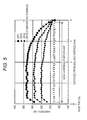
- Fig. 5 enlarges the measurement results at positions in the graph of Fig. 4 from the base end 30s of the ground electrode 30 to a position at a distance of 4 mm from the base end 30s.
- the hardness of the sample SP10 in the above described range is approximately constant at 180 Hv.
- the hardness of the samples SP01 to SP03 is slightly low at the position at a distance of 0.1 mm from the base end 30s of the ground electrode 30 (the position at the most base end side of the high hardness portion HHP).
- the hardness distribution of the samples SP01 to SP03 is categorizable into three portions, a first portion, a second portion, and a third portion.
- the hardness increases as a distance from the base end 30s increases.
- the hardness is approximately constant and flat.
- the hardness gradually decreases.
- the first portion in which the hardness increases, extends from the position at a distance of 0.1 mm from the base end 30s of the ground electrode 30 to a position at a distance of 0.3 mm from the base end 30s.
- the flat second portion extends from the position at a distance of 0.3 mm from the base end 30s to a position at a distance of 1.8 mm from the base end 30s.
- the third portion in which the hardness decreases, extends from the position at a distance of 1.8 mm from the base end 30s to the position at a distance of 4 mm from the base end 30s.
- the hardness at the position at the most base end 30s side in the high hardness portion HHP and the hardness at the position at a distance of 3 mm from the base end 30s show approximately equal value, which is relatively high value.
- a position at a distance of 3.9 mm from the base end 30s of the ground electrode 30 is equivalent to a position at the distal end side in the high hardness portion HHP, which is opposite side of the base end 30s of the ground electrode 30.
- the high hardness portion HHP preferably has the lowest hardness at the distal end of the high hardness portion HHP. The reason is that if the high hardness portion HHP has the lowest hardness at the distal end portion of the high hardness portion HHP, bending workability of a portion at further distal end side thereof (namely, the low hardness portion LHP) can be enhanced.
- the position in the high hardness portion HHP at a distance of 0.1 mm from the base end 30s of the ground electrode 30 is equivalent to the position at the most base end side of the high hardness portion HHP. It is preferred that the hardness at the position at the most base end side of the high hardness portion HHP and the hardness at the position at the most distal end side of the high hardness portion HHP are lower than the highest hardness of the high hardness portion HHP. The following is the reason. Namely, the thermal conduction between the ground electrode 30 and the metal shell 50 can be enhanced by making the hardness at the position at the most base end side of the high hardness portion HHP lower than the highest hardness of the high hardness portion HHP. This increases the heat conductivity of the ground electrode 30.
- the bending workability of the ground electrode 30 can be enhanced by making the hardness at the position at the most distal end side of the high hardness portion HHP lower than the highest hardness of the high hardness portion HHP.
- the test result regarding the heat conductivity of the ground electrode 30 will be described later.
- the value of the highest hardness in the low hardness portion LHP is 190 Hv to 200 Hv.
- the high hardness portion HHP is a portion that has the hardness higher than the highest hardness of the low hardness portion LHP. Therefore, in the example of Fig. 5 , the high hardness portion HHP extends from the position at a distance of 0.1 mm from the base end 30s of the ground electrode 30 to the position at a distance of 3.9 mm from the base end 30s.
- the range of the high hardness portion HHP can be controlled by adjusting the height of the auxiliary jig 320 in Fig.
- the high hardness portion HHP at least includes the range from the position at a distance of 0.1 mm from the base end 30s of the ground electrode 30 to the position at a distance of 3 mm from the base end 30s.
- Fig. 6 illustrates the result of the breakage resistance test for four types of samples SP01 to SP03 and SP10 illustrated in Figs. 4 and 5 .
- the breakage resistance test is carried out based on "ISO 11565 3.4.4" as follows: Namely, the samples are vibrated with an acceleration of 30 G in the horizontal direction and the vertical direction respectively for 8 hours (16 hours in total). During the vibration, the vibration frequency sweeps back and forth between 50 Hz and 500 Hz at a changing rate of one octave per minute. After that, the existence of breakage in the ground electrode 30 is checked. For example, as the sample SP01, one hundred samples are made under the identical condition. The breakage resistance test is carried out with these one hundred samples. The same applies to the other samples SP02, SP03, and SP10.
- the left half of Fig. 6 illustrates: a position where a breakage is caused during the breakage resistance test; a count of samples that have a breakage caused; and a determination result of the breakage resistance test for the four types of samples SP01 to SP03 and SP10.
- the breakage resistance of the ground electrode 30 can be enhanced by increasing the hardness at the positions at a distance of equal to or less than 3 mm from the base end 30s.
- the samples SP01 to SP03 In the case of the samples SP01 to SP03, two to six samples out of one hundred samples have a breakage. These numbers are substantially fewer than the count of the samples SP10 with a breakage, which is the comparative example.
- the samples SP01 to SP03 having the high hardness portion HHP show the enhanced breakage resistance as compared with the sample SP10 as the comparative example.
- a breakage easily occurs at the positions at a distance of equal to or less than 3 mm from the base end 30s.
- the high hardness portion HHP at least includes the range from the position at a distance of 0.1 mm from the base end 30s of the ground electrode 30 to the position at a distance of 3 mm from the base end 30s.
- the first sample SP01 shows the most satisfactory breakage resistance.
- the second sample SP02 and the third sample SP03 show the second most satisfactory breakage resistance.
- the difference ⁇ HV between the lowest hardness HV1 in the range of the ground electrode 30 from the base end 30s to the position at a distance of 3 mm from the base end 30s and the hardness HV2 of the bent portion 30b is 20 Hv.
- the breakage resistance of the sample SP10 which is the comparative example
- the high hardness portion HHP is formed in the ground electrode 30 even though the value of the difference ⁇ HV of the hardness is equal to or less than 20 Hv.
- the difference ⁇ HV is preferably equal to or more than 20 Hv for further enhancing the breakage resistance.
- Figs. 7A and 7B are explanatory views illustrating the result of a temperature test for the joining surfaces of the metal shells of the various kinds of samples.
- the horizontal axis of the graph in Fig. 7A indicates the hardness of the most base end portion of the ground electrode 30.
- the most base end portion of the ground electrode 30 means the portion at a distance of 0.1 mm from the base end 30s of the ground electrode 30 in Fig. 5 .
- the vertical axis of the graph in Fig. 7B indicates the temperature of the joining surface of the metal shell 50.
- the temperature of the joining surface of the metal shell 50 is measured with maintaining the temperature of a portion at a distance of 10 mm from the base end 30s of the ground electrode 30 at 1000°C.
- the joining surface of the metal shell 50 means an inner surface of the metal shell 50 that is equivalent to the base end 30s of the ground electrode 30 as shown in Figs. 3A and 3B .
- the temperature of the joining surface of the metal shell 50 is a value obtained by measuring, using a thermocouple, the temperature of the inner surface of the metal shell 50 at the positon at a distance of 0.3 mm from the joining surface.
- Figs. 7A and 7B are the identical values illustrated in Figs. 4 and 5 .
- Figs. 7A and 7B also illustrate the result of the hardness measurement and temperature measurement of another kind of sample SP04 in addition to the samples SP01 to SP03 and SP10.
- the hardness of the most base end portion of the ground electrode 30 is 400 Hv, which is the highest among the all samples.
- the temperature of the joining surface of the metal shell 50 tends to be higher.
- the temperature of the joining surface of the metal shell 50 is an index that indicates the heat conductivity of the ground electrode 30. Namely, as the temperature of the joining surface of the metal shell 50 decreases, the ground electrode 30 preferably shows more excellent heat conductivity. Accordingly, in terms of the heat conductivity of the ground electrode 30, it is preferred that the hardness of the most base end portion of the ground electrode 30 is not excessively high. For example, the hardness of the most base end portion of the ground electrode 30 is preferably equal to or less than 300 Hv.
- spark plugs having various configurations other than the configuration illustrated in Fig. 1 can be applied to the technique of this disclosure.
- specific forms of a terminal metal fitting and an insulator may have various shapes.
- the ground electrode member 30p is bent in the manufacturing processes of Figs. 2A to 2I .
- the ground electrode member 30p may be bent in other processes.
- another process other than these manufacturing processes may be added during the first to third manufacturing processes of the bending process illustrated in Figs. 2C, 2E, and 2H .
- the plating process may be carried out on the metal shell 50 to which the ground electrode member 30p is joined, for example, after the first manufacturing process ( Fig. 2C ) and before the second manufacturing process ( Fig. 2E ).
Landscapes
- Engineering & Computer Science (AREA)
- Manufacturing & Machinery (AREA)
- Spark Plugs (AREA)
- Ignition Installations For Internal Combustion Engines (AREA)
Applications Claiming Priority (1)
| Application Number | Priority Date | Filing Date | Title |
|---|---|---|---|
| JP2014104963A JP5990216B2 (ja) | 2014-05-21 | 2014-05-21 | スパークプラグ |
Publications (2)
| Publication Number | Publication Date |
|---|---|
| EP2947731A1 true EP2947731A1 (de) | 2015-11-25 |
| EP2947731B1 EP2947731B1 (de) | 2018-11-21 |
Family
ID=53180643
Family Applications (1)
| Application Number | Title | Priority Date | Filing Date |
|---|---|---|---|
| EP15168244.0A Active EP2947731B1 (de) | 2014-05-21 | 2015-05-19 | Zündkerze |
Country Status (4)
| Country | Link |
|---|---|
| US (1) | US9197037B1 (de) |
| EP (1) | EP2947731B1 (de) |
| JP (1) | JP5990216B2 (de) |
| CN (1) | CN105098603B (de) |
Families Citing this family (1)
| Publication number | Priority date | Publication date | Assignee | Title |
|---|---|---|---|---|
| JP7543955B2 (ja) | 2021-03-16 | 2024-09-03 | 株式会社デンソー | スパークプラグ、スパークプラグの製造方法 |
Citations (5)
| Publication number | Priority date | Publication date | Assignee | Title |
|---|---|---|---|---|
| JP2010080059A (ja) | 2007-09-17 | 2010-04-08 | Ngk Spark Plug Co Ltd | スパークプラグ |
| EP2323233A1 (de) * | 2008-09-02 | 2011-05-18 | NGK Spark Plug Co., Ltd. | Zündkerze |
| JP2012160351A (ja) | 2011-02-01 | 2012-08-23 | Ngk Spark Plug Co Ltd | スパークプラグ及びその製造方法 |
| JP2013012462A (ja) | 2011-05-27 | 2013-01-17 | Ngk Spark Plug Co Ltd | スパークプラグ |
| JP2013222676A (ja) | 2012-04-19 | 2013-10-28 | Ngk Spark Plug Co Ltd | スパークプラグ |
Family Cites Families (9)
| Publication number | Priority date | Publication date | Assignee | Title |
|---|---|---|---|---|
| JP3856551B2 (ja) * | 1997-11-19 | 2006-12-13 | 日本特殊陶業株式会社 | スパークプラグ |
| JP3950368B2 (ja) | 2002-06-05 | 2007-08-01 | 三菱重工業株式会社 | 分散電源システムおよびその運用方法、並びに運用プログラム |
| JP4303146B2 (ja) * | 2004-02-26 | 2009-07-29 | 日本特殊陶業株式会社 | スパークプラグ |
| CN102017340B (zh) * | 2008-04-24 | 2013-06-12 | 日本特殊陶业株式会社 | 火花塞 |
| JP4864065B2 (ja) * | 2008-11-05 | 2012-01-25 | 日本特殊陶業株式会社 | スパークプラグ |
| BR112013015609A2 (pt) * | 2010-12-20 | 2018-07-24 | Ngk Spark Plug Co., Ltd | vela de ignição e método de fabricação da mesma |
| JP5456083B2 (ja) * | 2011-02-10 | 2014-03-26 | 日本特殊陶業株式会社 | スパークプラグ |
| JP2012256445A (ja) * | 2011-06-07 | 2012-12-27 | Denso Corp | 内燃機関用のスパークプラグ |
| JP5809673B2 (ja) * | 2013-09-09 | 2015-11-11 | 日本特殊陶業株式会社 | 点火プラグ |
-
2014
- 2014-05-21 JP JP2014104963A patent/JP5990216B2/ja active Active
-
2015
- 2015-05-19 EP EP15168244.0A patent/EP2947731B1/de active Active
- 2015-05-19 US US14/716,163 patent/US9197037B1/en active Active
- 2015-05-21 CN CN201510262849.0A patent/CN105098603B/zh active Active
Patent Citations (5)
| Publication number | Priority date | Publication date | Assignee | Title |
|---|---|---|---|---|
| JP2010080059A (ja) | 2007-09-17 | 2010-04-08 | Ngk Spark Plug Co Ltd | スパークプラグ |
| EP2323233A1 (de) * | 2008-09-02 | 2011-05-18 | NGK Spark Plug Co., Ltd. | Zündkerze |
| JP2012160351A (ja) | 2011-02-01 | 2012-08-23 | Ngk Spark Plug Co Ltd | スパークプラグ及びその製造方法 |
| JP2013012462A (ja) | 2011-05-27 | 2013-01-17 | Ngk Spark Plug Co Ltd | スパークプラグ |
| JP2013222676A (ja) | 2012-04-19 | 2013-10-28 | Ngk Spark Plug Co Ltd | スパークプラグ |
Also Published As
| Publication number | Publication date |
|---|---|
| JP2015220194A (ja) | 2015-12-07 |
| CN105098603A (zh) | 2015-11-25 |
| US20150340843A1 (en) | 2015-11-26 |
| EP2947731B1 (de) | 2018-11-21 |
| JP5990216B2 (ja) | 2016-09-07 |
| US9197037B1 (en) | 2015-11-24 |
| CN105098603B (zh) | 2017-05-24 |
Similar Documents
| Publication | Publication Date | Title |
|---|---|---|
| EP2672588B1 (de) | Zündkerze | |
| US8106572B2 (en) | Spark plug and process for producing the spark plug | |
| KR101521495B1 (ko) | 스파크 플러그 전극 구성 | |
| US10826261B2 (en) | Method for manufacturing terminal-equipped electric wire, and terminal-equipped electric wire | |
| JP6634927B2 (ja) | スパークプラグ及びスパークプラグの製造方法 | |
| CN102738627A (zh) | 弹簧接触组件 | |
| US9083155B2 (en) | Spark plug with an improved separation resistance of a noble metal tip | |
| JP2009054579A (ja) | 内燃機関用のスパークプラグ及びその製造方法 | |
| US9997885B2 (en) | Method and device for producing a cable and cable produced by the method | |
| EP2947731B1 (de) | Zündkerze | |
| EP2701459A1 (de) | Keramische heizvorrichtung und herstellungsverfahren dafür | |
| JP6326320B2 (ja) | 圧着端子の製造方法 | |
| JP6451148B2 (ja) | 内燃機関用のスパークプラグ及びその製造方法 | |
| JP2021111530A (ja) | 評価治具 | |
| EP1739791A1 (de) | Crimpkontakt und Gassensor | |
| CN106911081B (zh) | 火花塞 | |
| CN109416292A (zh) | 压力传感器 | |
| US8523625B2 (en) | Method of manufacturing spark plug | |
| JP6234956B2 (ja) | スパークプラグの製造方法 | |
| JP4475100B2 (ja) | 電気接続用端子の取り付け構造およびその製造方法 | |
| JP5115128B2 (ja) | リード修正装置 | |
| EP3214708A1 (de) | Zündkerze | |
| US20150340847A1 (en) | Manufacturing method of spark plug | |
| WO2025040722A1 (de) | Sensorbaugruppe und verfahren zur herstellung einer sensorbaugruppe | |
| US10293397B2 (en) | Metal wire and electric wire |
Legal Events
| Date | Code | Title | Description |
|---|---|---|---|
| PUAI | Public reference made under article 153(3) epc to a published international application that has entered the european phase |
Free format text: ORIGINAL CODE: 0009012 |
|
| AK | Designated contracting states |
Kind code of ref document: A1 Designated state(s): AL AT BE BG CH CY CZ DE DK EE ES FI FR GB GR HR HU IE IS IT LI LT LU LV MC MK MT NL NO PL PT RO RS SE SI SK SM TR |
|
| AX | Request for extension of the european patent |
Extension state: BA ME |
|
| 17P | Request for examination filed |
Effective date: 20151222 |
|
| RBV | Designated contracting states (corrected) |
Designated state(s): AL AT BE BG CH CY CZ DE DK EE ES FI FR GB GR HR HU IE IS IT LI LT LU LV MC MK MT NL NO PL PT RO RS SE SI SK SM TR |
|
| GRAP | Despatch of communication of intention to grant a patent |
Free format text: ORIGINAL CODE: EPIDOSNIGR1 |
|
| STAA | Information on the status of an ep patent application or granted ep patent |
Free format text: STATUS: GRANT OF PATENT IS INTENDED |
|
| INTG | Intention to grant announced |
Effective date: 20180903 |
|
| GRAS | Grant fee paid |
Free format text: ORIGINAL CODE: EPIDOSNIGR3 |
|
| GRAA | (expected) grant |
Free format text: ORIGINAL CODE: 0009210 |
|
| STAA | Information on the status of an ep patent application or granted ep patent |
Free format text: STATUS: THE PATENT HAS BEEN GRANTED |
|
| AK | Designated contracting states |
Kind code of ref document: B1 Designated state(s): AL AT BE BG CH CY CZ DE DK EE ES FI FR GB GR HR HU IE IS IT LI LT LU LV MC MK MT NL NO PL PT RO RS SE SI SK SM TR |
|
| REG | Reference to a national code |
Ref country code: CH Ref legal event code: EP |
|
| REG | Reference to a national code |
Ref country code: IE Ref legal event code: FG4D |
|
| REG | Reference to a national code |
Ref country code: DE Ref legal event code: R096 Ref document number: 602015019984 Country of ref document: DE |
|
| REG | Reference to a national code |
Ref country code: AT Ref legal event code: REF Ref document number: 1068653 Country of ref document: AT Kind code of ref document: T Effective date: 20181215 |
|
| REG | Reference to a national code |
Ref country code: NL Ref legal event code: MP Effective date: 20181121 |
|
| REG | Reference to a national code |
Ref country code: AT Ref legal event code: MK05 Ref document number: 1068653 Country of ref document: AT Kind code of ref document: T Effective date: 20181121 |
|
| PG25 | Lapsed in a contracting state [announced via postgrant information from national office to epo] |
Ref country code: FI Free format text: LAPSE BECAUSE OF FAILURE TO SUBMIT A TRANSLATION OF THE DESCRIPTION OR TO PAY THE FEE WITHIN THE PRESCRIBED TIME-LIMIT Effective date: 20181121 Ref country code: NO Free format text: LAPSE BECAUSE OF FAILURE TO SUBMIT A TRANSLATION OF THE DESCRIPTION OR TO PAY THE FEE WITHIN THE PRESCRIBED TIME-LIMIT Effective date: 20190221 Ref country code: IS Free format text: LAPSE BECAUSE OF FAILURE TO SUBMIT A TRANSLATION OF THE DESCRIPTION OR TO PAY THE FEE WITHIN THE PRESCRIBED TIME-LIMIT Effective date: 20190321 Ref country code: HR Free format text: LAPSE BECAUSE OF FAILURE TO SUBMIT A TRANSLATION OF THE DESCRIPTION OR TO PAY THE FEE WITHIN THE PRESCRIBED TIME-LIMIT Effective date: 20181121 Ref country code: LT Free format text: LAPSE BECAUSE OF FAILURE TO SUBMIT A TRANSLATION OF THE DESCRIPTION OR TO PAY THE FEE WITHIN THE PRESCRIBED TIME-LIMIT Effective date: 20181121 Ref country code: BG Free format text: LAPSE BECAUSE OF FAILURE TO SUBMIT A TRANSLATION OF THE DESCRIPTION OR TO PAY THE FEE WITHIN THE PRESCRIBED TIME-LIMIT Effective date: 20190221 Ref country code: ES Free format text: LAPSE BECAUSE OF FAILURE TO SUBMIT A TRANSLATION OF THE DESCRIPTION OR TO PAY THE FEE WITHIN THE PRESCRIBED TIME-LIMIT Effective date: 20181121 Ref country code: LV Free format text: LAPSE BECAUSE OF FAILURE TO SUBMIT A TRANSLATION OF THE DESCRIPTION OR TO PAY THE FEE WITHIN THE PRESCRIBED TIME-LIMIT Effective date: 20181121 Ref country code: AT Free format text: LAPSE BECAUSE OF FAILURE TO SUBMIT A TRANSLATION OF THE DESCRIPTION OR TO PAY THE FEE WITHIN THE PRESCRIBED TIME-LIMIT Effective date: 20181121 |
|
| PG25 | Lapsed in a contracting state [announced via postgrant information from national office to epo] |
Ref country code: PT Free format text: LAPSE BECAUSE OF FAILURE TO SUBMIT A TRANSLATION OF THE DESCRIPTION OR TO PAY THE FEE WITHIN THE PRESCRIBED TIME-LIMIT Effective date: 20190321 Ref country code: AL Free format text: LAPSE BECAUSE OF FAILURE TO SUBMIT A TRANSLATION OF THE DESCRIPTION OR TO PAY THE FEE WITHIN THE PRESCRIBED TIME-LIMIT Effective date: 20181121 Ref country code: RS Free format text: LAPSE BECAUSE OF FAILURE TO SUBMIT A TRANSLATION OF THE DESCRIPTION OR TO PAY THE FEE WITHIN THE PRESCRIBED TIME-LIMIT Effective date: 20181121 Ref country code: NL Free format text: LAPSE BECAUSE OF FAILURE TO SUBMIT A TRANSLATION OF THE DESCRIPTION OR TO PAY THE FEE WITHIN THE PRESCRIBED TIME-LIMIT Effective date: 20181121 Ref country code: GR Free format text: LAPSE BECAUSE OF FAILURE TO SUBMIT A TRANSLATION OF THE DESCRIPTION OR TO PAY THE FEE WITHIN THE PRESCRIBED TIME-LIMIT Effective date: 20190222 Ref country code: SE Free format text: LAPSE BECAUSE OF FAILURE TO SUBMIT A TRANSLATION OF THE DESCRIPTION OR TO PAY THE FEE WITHIN THE PRESCRIBED TIME-LIMIT Effective date: 20181121 |
|
| PG25 | Lapsed in a contracting state [announced via postgrant information from national office to epo] |
Ref country code: IT Free format text: LAPSE BECAUSE OF FAILURE TO SUBMIT A TRANSLATION OF THE DESCRIPTION OR TO PAY THE FEE WITHIN THE PRESCRIBED TIME-LIMIT Effective date: 20181121 Ref country code: DK Free format text: LAPSE BECAUSE OF FAILURE TO SUBMIT A TRANSLATION OF THE DESCRIPTION OR TO PAY THE FEE WITHIN THE PRESCRIBED TIME-LIMIT Effective date: 20181121 Ref country code: PL Free format text: LAPSE BECAUSE OF FAILURE TO SUBMIT A TRANSLATION OF THE DESCRIPTION OR TO PAY THE FEE WITHIN THE PRESCRIBED TIME-LIMIT Effective date: 20181121 Ref country code: CZ Free format text: LAPSE BECAUSE OF FAILURE TO SUBMIT A TRANSLATION OF THE DESCRIPTION OR TO PAY THE FEE WITHIN THE PRESCRIBED TIME-LIMIT Effective date: 20181121 |
|
| REG | Reference to a national code |
Ref country code: DE Ref legal event code: R097 Ref document number: 602015019984 Country of ref document: DE |
|
| PG25 | Lapsed in a contracting state [announced via postgrant information from national office to epo] |
Ref country code: SK Free format text: LAPSE BECAUSE OF FAILURE TO SUBMIT A TRANSLATION OF THE DESCRIPTION OR TO PAY THE FEE WITHIN THE PRESCRIBED TIME-LIMIT Effective date: 20181121 Ref country code: RO Free format text: LAPSE BECAUSE OF FAILURE TO SUBMIT A TRANSLATION OF THE DESCRIPTION OR TO PAY THE FEE WITHIN THE PRESCRIBED TIME-LIMIT Effective date: 20181121 Ref country code: EE Free format text: LAPSE BECAUSE OF FAILURE TO SUBMIT A TRANSLATION OF THE DESCRIPTION OR TO PAY THE FEE WITHIN THE PRESCRIBED TIME-LIMIT Effective date: 20181121 Ref country code: SM Free format text: LAPSE BECAUSE OF FAILURE TO SUBMIT A TRANSLATION OF THE DESCRIPTION OR TO PAY THE FEE WITHIN THE PRESCRIBED TIME-LIMIT Effective date: 20181121 |
|
| PLBE | No opposition filed within time limit |
Free format text: ORIGINAL CODE: 0009261 |
|
| STAA | Information on the status of an ep patent application or granted ep patent |
Free format text: STATUS: NO OPPOSITION FILED WITHIN TIME LIMIT |
|
| 26N | No opposition filed |
Effective date: 20190822 |
|
| PG25 | Lapsed in a contracting state [announced via postgrant information from national office to epo] |
Ref country code: SI Free format text: LAPSE BECAUSE OF FAILURE TO SUBMIT A TRANSLATION OF THE DESCRIPTION OR TO PAY THE FEE WITHIN THE PRESCRIBED TIME-LIMIT Effective date: 20181121 |
|
| REG | Reference to a national code |
Ref country code: CH Ref legal event code: PL |
|
| GBPC | Gb: european patent ceased through non-payment of renewal fee |
Effective date: 20190519 |
|
| PG25 | Lapsed in a contracting state [announced via postgrant information from national office to epo] |
Ref country code: LI Free format text: LAPSE BECAUSE OF NON-PAYMENT OF DUE FEES Effective date: 20190531 Ref country code: CH Free format text: LAPSE BECAUSE OF NON-PAYMENT OF DUE FEES Effective date: 20190531 Ref country code: MC Free format text: LAPSE BECAUSE OF FAILURE TO SUBMIT A TRANSLATION OF THE DESCRIPTION OR TO PAY THE FEE WITHIN THE PRESCRIBED TIME-LIMIT Effective date: 20181121 |
|
| REG | Reference to a national code |
Ref country code: BE Ref legal event code: MM Effective date: 20190531 |
|
| PG25 | Lapsed in a contracting state [announced via postgrant information from national office to epo] |
Ref country code: LU Free format text: LAPSE BECAUSE OF NON-PAYMENT OF DUE FEES Effective date: 20190519 |
|
| PG25 | Lapsed in a contracting state [announced via postgrant information from national office to epo] |
Ref country code: TR Free format text: LAPSE BECAUSE OF FAILURE TO SUBMIT A TRANSLATION OF THE DESCRIPTION OR TO PAY THE FEE WITHIN THE PRESCRIBED TIME-LIMIT Effective date: 20181121 |
|
| PG25 | Lapsed in a contracting state [announced via postgrant information from national office to epo] |
Ref country code: GB Free format text: LAPSE BECAUSE OF NON-PAYMENT OF DUE FEES Effective date: 20190519 Ref country code: IE Free format text: LAPSE BECAUSE OF NON-PAYMENT OF DUE FEES Effective date: 20190519 |
|
| PG25 | Lapsed in a contracting state [announced via postgrant information from national office to epo] |
Ref country code: BE Free format text: LAPSE BECAUSE OF NON-PAYMENT OF DUE FEES Effective date: 20190531 |
|
| PG25 | Lapsed in a contracting state [announced via postgrant information from national office to epo] |
Ref country code: FR Free format text: LAPSE BECAUSE OF NON-PAYMENT OF DUE FEES Effective date: 20190531 |
|
| PG25 | Lapsed in a contracting state [announced via postgrant information from national office to epo] |
Ref country code: CY Free format text: LAPSE BECAUSE OF FAILURE TO SUBMIT A TRANSLATION OF THE DESCRIPTION OR TO PAY THE FEE WITHIN THE PRESCRIBED TIME-LIMIT Effective date: 20181121 |
|
| PG25 | Lapsed in a contracting state [announced via postgrant information from national office to epo] |
Ref country code: MT Free format text: LAPSE BECAUSE OF FAILURE TO SUBMIT A TRANSLATION OF THE DESCRIPTION OR TO PAY THE FEE WITHIN THE PRESCRIBED TIME-LIMIT Effective date: 20181121 Ref country code: HU Free format text: LAPSE BECAUSE OF FAILURE TO SUBMIT A TRANSLATION OF THE DESCRIPTION OR TO PAY THE FEE WITHIN THE PRESCRIBED TIME-LIMIT; INVALID AB INITIO Effective date: 20150519 |
|
| PG25 | Lapsed in a contracting state [announced via postgrant information from national office to epo] |
Ref country code: MK Free format text: LAPSE BECAUSE OF FAILURE TO SUBMIT A TRANSLATION OF THE DESCRIPTION OR TO PAY THE FEE WITHIN THE PRESCRIBED TIME-LIMIT Effective date: 20181121 |
|
| P01 | Opt-out of the competence of the unified patent court (upc) registered |
Effective date: 20230512 |
|
| REG | Reference to a national code |
Ref country code: DE Ref legal event code: R081 Ref document number: 602015019984 Country of ref document: DE Owner name: NITERRA CO., LTD., NAGOYA-SHI, JP Free format text: FORMER OWNER: NGK SPARK PLUG CO., LTD., NAGOYA-SHI, AICHI, JP |
|
| PGFP | Annual fee paid to national office [announced via postgrant information from national office to epo] |
Ref country code: DE Payment date: 20260402 Year of fee payment: 12 |