EP2946876B1 - Beweglicher Reitstock - Google Patents
Beweglicher Reitstock Download PDFInfo
- Publication number
- EP2946876B1 EP2946876B1 EP14193585.8A EP14193585A EP2946876B1 EP 2946876 B1 EP2946876 B1 EP 2946876B1 EP 14193585 A EP14193585 A EP 14193585A EP 2946876 B1 EP2946876 B1 EP 2946876B1
- Authority
- EP
- European Patent Office
- Prior art keywords
- drive motor
- ball screw
- tail stock
- brake
- workpiece
- Prior art date
- Legal status (The legal status is an assumption and is not a legal conclusion. Google has not performed a legal analysis and makes no representation as to the accuracy of the status listed.)
- Active
Links
Images


Classifications
-
- B—PERFORMING OPERATIONS; TRANSPORTING
- B23—MACHINE TOOLS; METAL-WORKING NOT OTHERWISE PROVIDED FOR
- B23B—TURNING; BORING
- B23B23/00—Tailstocks; Centres
-
- B—PERFORMING OPERATIONS; TRANSPORTING
- B23—MACHINE TOOLS; METAL-WORKING NOT OTHERWISE PROVIDED FOR
- B23Q—DETAILS, COMPONENTS, OR ACCESSORIES FOR MACHINE TOOLS, e.g. ARRANGEMENTS FOR COPYING OR CONTROLLING; MACHINE TOOLS IN GENERAL CHARACTERISED BY THE CONSTRUCTION OF PARTICULAR DETAILS OR COMPONENTS; COMBINATIONS OR ASSOCIATIONS OF METAL-WORKING MACHINES, NOT DIRECTED TO A PARTICULAR RESULT
- B23Q15/00—Automatic control or regulation of feed movement, cutting velocity or position of tool or work
- B23Q15/007—Automatic control or regulation of feed movement, cutting velocity or position of tool or work while the tool acts upon the workpiece
- B23Q15/08—Control or regulation of cutting velocity
-
- G—PHYSICS
- G01—MEASURING; TESTING
- G01L—MEASURING FORCE, STRESS, TORQUE, WORK, MECHANICAL POWER, MECHANICAL EFFICIENCY, OR FLUID PRESSURE
- G01L3/00—Measuring torque, work, mechanical power, or mechanical efficiency, in general
-
- B—PERFORMING OPERATIONS; TRANSPORTING
- B23—MACHINE TOOLS; METAL-WORKING NOT OTHERWISE PROVIDED FOR
- B23B—TURNING; BORING
- B23B2250/00—Compensating adverse effects during turning, boring or drilling
- B23B2250/16—Damping of vibrations
-
- Y—GENERAL TAGGING OF NEW TECHNOLOGICAL DEVELOPMENTS; GENERAL TAGGING OF CROSS-SECTIONAL TECHNOLOGIES SPANNING OVER SEVERAL SECTIONS OF THE IPC; TECHNICAL SUBJECTS COVERED BY FORMER USPC CROSS-REFERENCE ART COLLECTIONS [XRACs] AND DIGESTS
- Y10—TECHNICAL SUBJECTS COVERED BY FORMER USPC
- Y10T—TECHNICAL SUBJECTS COVERED BY FORMER US CLASSIFICATION
- Y10T82/00—Turning
- Y10T82/25—Lathe
- Y10T82/2564—Tailstock
Definitions
- the present invention relates to a moving mechanism for a tail stock that is moved by means of a ball screw and holds a workpiece.
- the hydraulic cylinder also requires complicated and cumbersome operations for the control because the pressure force applied to the workpiece is adjusted by a manual pressure reducing valve and because the change in oil pressure is slow. Hence, the hydraulic cylinder is not suitable for speedy control.
- Patent Document 1 proposes a structure of sliding a tail stock with a ball screw (description on "tail stock 21" and “ball screw device” in FIG. 1 and paragraph [0010]) to replace the method using the hydraulic cylinder having the technical problems described above.
- Patent Document 1 no specific structure acting as a control mechanism for moving the tail stock with the ball screw and applying pressure to the workpiece is described.
- Patent Document 3 discloses another example of a tail stock and is directed to a tailstock control device.
- the device comprises a servo motor which drives a driving system. It can measure an output torque value of the servo motor and stop the same when it reaches a limit torque value.
- Patent Document KR 2013 0083746 A shows a tail stock equipment according to the preamble of claim 1. It also shows a method of controlling the operation of a tail stock equipment comprising a tail stock for holding a workpiece, a ball screw for supporting the tail stock, a motor and a brake.
- An object of the present invention is to provide a structure of a tail stock moving mechanism, in which a tail stock that holds a workpiece with a predetermined pressure force is moved by means of a ball screw and in which a control required for holding the workpiece with the predetermined pressure force is implemented.
- a ball screw may be adopted which can be operated in a space smaller than that for the hydraulic cylinder. And the pressure force sufficient for holding the workpiece is secured by appropriately selecting the torque generated by the drive motor, and operating the brake of the ball screw. Furthermore, faster control can be achieved compared to a case where the hydraulic cylinder is used.
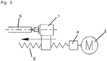
- each of the basic structures (1), (2), (3) has a tail stock which applies pressure to a workpiece, a ball screw which rotates to move the tail stock and includes a brake for ensuring the pressing state, and a drive motor for the ball screw, as components.
- the drive motor is disposed on the opposite side of the workpiece with the tail stock and the ball screw disposed in between.
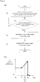
- control includes the steps of:
- FIG. 4(b) shows how the torque of the drive motor changes based on the control.
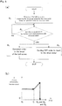
- control includes the steps of:
- FIG. 5(b) shows how the torque of the drive motor changes based on the control.
- the control by a program as shown in FIG. 6(a) is performed in the basic structure (3).
- control includes the steps of:
- FIG. 6(b) shows how the torque of the drive motor changes based on the control.
- step (S1) of a in FIG. 4(a) which is common among the basic structures (1), (2), (3), it may be checked whether the ball screw is at a position of the workpiece and where the ball screw has approached to the workpiece, and the torque generated by the drive motor may be detected after the ball screw has reached this approach position.
- step (S2) of b in FIG.4(a) , FIG.5(a) , and FIG.6(a) which is common among the basic structures (1), (2), (3), it may be determined whether the tail stock has reached a limit of movement after determining whether a torque generated by the drive motor has reached the predetermined reference. Based on the determinations, the operation of the brake or the cutting off of the input from the power supply to the drive motor in the subsequent step may be performed even when the torque has not reached the reference value, if the tail stock has reached the limit of movement.
- the drive motor has to generate a torque that is balanced with the reaction.
- the brake is operated to limit a rotation of the ball screw when the torque generated by the drive motor reaches the predetermined reference value; and the input from the power supply to the drive motor is cut off after the brake is operated.
- the abovementioned reference value may be set to prevent the excessive increase at the time of cutting off the power supply.
- the input from the power supply to the drive motor is cut off when the torque generated by the drive motor reaches the predetermined reference value, and then the brake is operated to limit a rotation of the ball screw.
- the brake is operated to limit a rotation of the ball screw.
- a design may be applied in which the inclination angle of the screw of the ball screw is set to be small so that the reverse rotation of the ball screw does not occur.
- the operation of the brake to limit a rotation of the ball screw and the cutting off of the input from the power supply to the drive motor are performed at the same time when the torque generated by the drive motor reaches the predetermined reference value.
- the brake is operated when the torque generated by the drive motor reaches the predetermined reference value.
- the tail stock supported by the ball screw can hold the workpiece with the pressure force corresponding to the torque.
- the torque generated by the drive motor corresponds to the pressure force produced by the movement of the ball screw.
- the torque in the drive motor is generally measured based on the input current to the drive motor or the power consumption in the drive motor that is in correspondence with the torque.
- a current based on counter electromotive force or a power consumption based on counter electromotive force in the drive motor more directly reflects the torque. Still, the input current or the power consumption can be more easily measured than the generation current or electric power.
- example 1 has the following features: a pipe that fits in close contact to a rear end of a workpiece and an outer circumference surface around the rear end that protrudes from a periphery of a protruding part that applies pressure to a rear end surface of the workpiece, wherein the pipe fits in close contact to a circumference of the protruding part.
- the pipe holds the workpiece while being in contact with and fitted on the workpiece.
- the tail stock can also be applied to have a vibration stopper effect.
- the pipe is prepared separately from the tail stock and uniquely in accordance with the diameter of the workpiece.
- the pipe contacts and fits on the rear end and a circumference surface of the read end of the workpiece, and the circumference of the protruding part of the tail stock, so that sufficient vibration stopper function can be exerted.
- example 2 has the following features: a pair of upper and lower bases is disposed on the ball screw, the tail stock and a vibration stopper are arranged side-by-side on an upper base plate in a direction orthogonal to the longitudinal direction of the ball screw, and the upper base is movable relative to a lower base plate in a direction orthogonal to the longitudinal direction of the ball screw or is fixed to the lower base plate in a direction orthogonal to the longitudinal direction of the ball screw.
- the workpiece can be applied with pressure by the tail stock and furthermore, after a process step for the workpiece has started, the vibration of the workpiece is prevented with fitting the vibration stopper.
- the present invention can hold almost any workpiece with required pressure force, and thus is extremely useful.
Landscapes
- Engineering & Computer Science (AREA)
- Mechanical Engineering (AREA)
- Physics & Mathematics (AREA)
- General Physics & Mathematics (AREA)
- Transmission Devices (AREA)
- Turning (AREA)
Claims (14)
- Reitstockausrüstung, umfassend:- einen Reitstock (1), der dazu konfiguriert ist, ein Werkstück (5) zu halten;- einen Kugelgewindetrieb (2), der dazu konfiguriert ist, den Reitstock (1) zu tragen;- einen Antriebsmotor (3), der dazu konfiguriert ist, den Kugelgewindetrieb (2) anzutreiben;- eine Bremse (4);dadurch gekennzeichnet, dass die Reitstockausrüstung ferner umfasst- ein Steuerprogramm, das dazu konfiguriert ist, die Bremse (4) zu betreiben, um eine Drehung des Kugelgewindetriebs (2) zu begrenzen, und eine Eingabe von einer Leistungszufuhr zu dem Antriebsmotor (3) zu unterbrechen, wenn ein detektiertes durch den Antriebsmotor (3) erzeugtes Drehmoment einen vorgegebenen Referenzwert erreicht, der der Druckkraft zum Halten des Werkstücks (5) entspricht.
- Reitstockausrüstung (1) nach Anspruch 1, wobei die Eingabe von der Leistungszufuhr zu dem Antriebsmotor (3) dazu gesteuert wird, unterbrochen zu werden, nachdem die Bremse (4) eine Drehung des Kugelgewindetriebs (2) begrenzt.
- Reitstockausrüstung (1) nach Anspruch 1, wobei die Bremse (4) betrieben wird, um die Drehung des Kugelgewindetriebs (2) zu begrenzen, nachdem die Eingabe von der Leistungszufuhr zu dem Antriebsmotor (3) unterbrochen wird.
- Reitstockausrüstung nach Anspruch 1, wobei die Bremse (4) betrieben wird, um die Drehung des Kugelgewindetriebs (2) zu derselben Zeit zu begrenzen, wenn die Eingabe von der Leistungszufuhr zu dem Antriebsmotor (3) dazu gesteuert wird, unterbrochen zu werden, wenn das Drehmoment einen vorgegebenen Referenzwert erreicht.
- Reitstockausrüstung (1) nach einem der Ansprüche 1 bis 4, wobei das durch den Antriebsmotor (3) erzeugte Drehmoment basierend auf einem Eingangsstrom zu dem Antriebsmotor (3) detektiert wird.
- Reitstockausrüstung (1) nach einem der Ansprüche 1 bis 4, wobei das durch den Antriebsmotor (3) erzeugte Drehmoment basierend auf einem Leistungsverbrauch in dem Antriebsmotor (3) detektiert wird.
- Reitstockausrüstung (1) nach einem der Ansprüche 1 bis 6, wobei ein Rohr (12) in engem Kontakt an ein Hinterende eines Werkstücks (5) passt und eine Außenumfangsoberfläche um das Hinterende herum von einem Umfang eines vorstehenden Teils (11) vorsteht, das Druck auf eine Hinterendoberfläche des Werkstücks (5) aufbringt, und das Rohr (12) in engem Kontakt an einen Umfang des vorstehenden Teils (11) passt.
- Reitstockausrüstung (1) nach einem der Ansprüche 1 bis 6, wobei ein Paar von oberen und unteren Basen auf dem Kugelgewindetrieb (2) angeordnet ist, der Reitstock (1) und ein Vibrationsstopper (7) Seite an Seite auf einer oberen Basisplatte (61) in einer Richtung orthogonal zu der Längsrichtung des Kugelgewindetriebs (2) angeordnet sind, und die obere Basis relativ zu einer unteren Basisplatte (62) in einer Richtung orthogonal zu der Längsrichtung des Kugelgewindetriebs (2) beweglich ist oder an der unteren Basisplatte (62) in einer Richtung orthogonal zu der Längsrichtung des Kugelgewindetriebs (2) fixiert ist.
- Verfahren zum Steuern des Betriebs einer Reitstockausrüstung, wobei die Reitstockausrüstung einen Reitstock (1) zum Halten eines Werkstücks, einen Kugelgewindetrieb (2) zum Tragen des Reitstocks (1), einen Motor (3) und eine Bremse (4) umfasst, wobei das Verfahren die Schritte umfasst:- Detektieren einer Bewegung des Reitstocks (1), die durch den Kugelgewindetrieb (2) verursacht wurde, und eines Drehmoments, das durch den Antriebsmotor (3) erzeugt wurde, der den Kugelgewindetrieb (2) antreibt; und- falls das detektierte durch den Antriebsmotor (3) erzeugte Drehmoment einen vorgegebenen Referenzwert erreicht, der der Druckkraft zum Halten des Werkstücks entspricht, Betreiben der Bremse (4), um eine Drehung des Kugelgewindetriebs (2) zu begrenzen; und Unterbrechen einer Eingabe von einer Leistungszufuhr zu dem Antriebsmotor (3).
- Verfahren nach Anspruch 9, wobei die Leistungszufuhr zu dem Antriebsmotor (3) nach einem Betreiben der Bremse (4) zum Begrenzen der Drehung des Kugelgewindetriebs (2) unterbrochen wird.
- Verfahren nach Anspruch 9, wobei die Bremse (4) zum Begrenzen einer Drehung des Kugelgewindetriebs (2) nach einem Unterbrechen der Leistungszufuhr zu dem Antriebsmotor (3) betrieben wird.
- Verfahren nach Anspruch 9, wobei der Betrieb der Bremse (4) zum Begrenzen der Drehung des Kugelgewindetriebs (2) und das Unterbrechen des Eingangs von der Leistungszufuhr zu derselben Zeit durchgeführt werden, wenn das durch den Antriebsmotor erzeugte Drehmoment den vorgegebenen Referenzwert erreicht.
- Verfahren nach einem der Ansprüche 9 bis 12, wobei das durch den Antriebsmotor (3) erzeugte Drehmoment basierend auf einem Eingangsstrom zu dem Antriebsmotor (3) detektiert wird.
- Verfahren nach einem der Ansprüche 9 bis 12, wobei das durch den Antriebsmotor (3) erzeugte Drehmoment basierend auf einem Leistungsverbrauch in dem Antriebsmotor (3) detektiert wird.
Applications Claiming Priority (1)
| Application Number | Priority Date | Filing Date | Title |
|---|---|---|---|
| JP2014103616A JP6312523B2 (ja) | 2014-05-19 | 2014-05-19 | 移動型テールストック |
Publications (2)
| Publication Number | Publication Date |
|---|---|
| EP2946876A1 EP2946876A1 (de) | 2015-11-25 |
| EP2946876B1 true EP2946876B1 (de) | 2021-03-03 |
Family
ID=52006825
Family Applications (1)
| Application Number | Title | Priority Date | Filing Date |
|---|---|---|---|
| EP14193585.8A Active EP2946876B1 (de) | 2014-05-19 | 2014-11-18 | Beweglicher Reitstock |
Country Status (7)
| Country | Link |
|---|---|
| US (1) | US9849513B2 (de) |
| EP (1) | EP2946876B1 (de) |
| JP (1) | JP6312523B2 (de) |
| KR (2) | KR20150133113A (de) |
| CN (1) | CN105081363A (de) |
| CA (2) | CA2870954C (de) |
| ES (1) | ES2860939T3 (de) |
Families Citing this family (4)
| Publication number | Priority date | Publication date | Assignee | Title |
|---|---|---|---|---|
| CN107598613B (zh) * | 2017-10-25 | 2024-03-15 | 锐奇控股股份有限公司 | 型材切割机工件夹持装置及型材切割机 |
| CN111283474B (zh) * | 2020-03-06 | 2021-02-09 | 秦皇岛华宇通电力科技有限公司 | 一种基于大数据的数控自动化设备故障检测系统 |
| WO2022118474A1 (ja) * | 2020-12-04 | 2022-06-09 | ヤマザキマザック株式会社 | 加工装置のテールストックの押し付け方法、加工装置、コンピュータプログラム、及び、コンピュータ読出可能な記憶媒体 |
| US20230189752A1 (en) * | 2021-12-17 | 2023-06-22 | Fast-Sexing Technologies Ulc | Devices, methods and systems for restraining, transporting and manipulating animals |
Citations (1)
| Publication number | Priority date | Publication date | Assignee | Title |
|---|---|---|---|---|
| KR20130083746A (ko) * | 2012-01-13 | 2013-07-23 | 현대위아 주식회사 | 심압대 추력 유지장치 |
Family Cites Families (24)
| Publication number | Priority date | Publication date | Assignee | Title |
|---|---|---|---|---|
| US2733627A (en) * | 1956-02-07 | Work holding tool | ||
| US2027568A (en) * | 1928-10-11 | 1936-01-14 | Monarch Machine Tool Co | Lathe |
| US3160041A (en) * | 1961-03-21 | 1964-12-08 | Landis Machine Co | Tailstock |
| JPS4934474U (de) * | 1972-06-27 | 1974-03-26 | ||
| JPS5560932U (de) * | 1978-10-17 | 1980-04-25 | ||
| JPS59216027A (ja) * | 1983-05-23 | 1984-12-06 | Jido Keisoku Kk | トルク検出装置 |
| JPH0753341B2 (ja) * | 1988-09-19 | 1995-06-07 | 日立精機株式会社 | プログラマブルテールストックによるワーク座標位置監視方法 |
| JPH0463603A (ja) * | 1990-06-29 | 1992-02-28 | Okuma Mach Works Ltd | 推力自動調整式心押台 |
| JPH0655310A (ja) * | 1992-08-11 | 1994-03-01 | Nakamura Tome Precision Ind Co Ltd | Ncテールストック及びその制御方法 |
| JPH06218630A (ja) | 1993-01-20 | 1994-08-09 | Nippon Seiko Kk | ナットねじ溝の加工方法及び加工装置 |
| JPH0767207A (ja) * | 1993-08-27 | 1995-03-10 | Toyota Autom Loom Works Ltd | バッテリ式フォークリフトの回生制動装置 |
| JPH1076402A (ja) | 1996-08-30 | 1998-03-24 | Yamazaki Mazak Corp | 工作機械における工具装着方法 |
| JP2000144256A (ja) | 1998-11-12 | 2000-05-26 | Fuji Denshi Kogyo Kk | 高周波焼入装置 |
| JP2002328707A (ja) * | 2001-04-27 | 2002-11-15 | Mitsubishi Electric Corp | 数値制御装置 |
| US7044840B2 (en) * | 2002-08-07 | 2006-05-16 | Toyoda Koki Kabushiki Kaisha | Grinding method and grinding machine |
| JP4199617B2 (ja) * | 2003-07-23 | 2008-12-17 | ヤマザキマザック株式会社 | 複合加工旋盤の心押台駆動装置 |
| JP4490835B2 (ja) * | 2005-01-20 | 2010-06-30 | 東洋機械金属株式会社 | 縦型射出成形機 |
| JP4575847B2 (ja) * | 2005-06-13 | 2010-11-04 | オークマ株式会社 | 心押台制御装置および心押動作の制御方法 |
| JP4644052B2 (ja) * | 2005-06-28 | 2011-03-02 | オークマ株式会社 | 心押台制御装置 |
| JP4446943B2 (ja) * | 2005-08-31 | 2010-04-07 | オークマ株式会社 | 心押台制御装置 |
| JP5015816B2 (ja) * | 2008-02-08 | 2012-08-29 | オークマ株式会社 | 心押台制御装置 |
| CN102095541B (zh) * | 2010-12-06 | 2012-06-27 | 东南大学 | 精密滚珠丝杠副摩擦机理研究实验台 |
| CN202701824U (zh) * | 2012-06-21 | 2013-01-30 | 重庆歇马机械曲轴有限公司 | 通用动力机曲轴杆部车加工夹具 |
| CN203316741U (zh) * | 2013-06-21 | 2013-12-04 | 山东德瑞数控设备股份有限公司 | 一种立式车床用尾座装置 |
-
2014
- 2014-05-19 JP JP2014103616A patent/JP6312523B2/ja active Active
- 2014-08-29 CN CN201410437074.1A patent/CN105081363A/zh active Pending
- 2014-09-24 KR KR1020140127725A patent/KR20150133113A/ko not_active Withdrawn
- 2014-11-13 CA CA2870954A patent/CA2870954C/en active Active
- 2014-11-13 CA CA3010281A patent/CA3010281C/en active Active
- 2014-11-18 EP EP14193585.8A patent/EP2946876B1/de active Active
- 2014-11-18 ES ES14193585T patent/ES2860939T3/es active Active
- 2014-12-16 US US14/571,905 patent/US9849513B2/en active Active
-
2017
- 2017-07-12 KR KR2020170003623U patent/KR20170002890U/ko not_active Ceased
Patent Citations (1)
| Publication number | Priority date | Publication date | Assignee | Title |
|---|---|---|---|---|
| KR20130083746A (ko) * | 2012-01-13 | 2013-07-23 | 현대위아 주식회사 | 심압대 추력 유지장치 |
Also Published As
| Publication number | Publication date |
|---|---|
| US20150328687A1 (en) | 2015-11-19 |
| KR20170002890U (ko) | 2017-08-14 |
| EP2946876A1 (de) | 2015-11-25 |
| JP2015217487A (ja) | 2015-12-07 |
| CA3010281C (en) | 2021-01-26 |
| CN105081363A (zh) | 2015-11-25 |
| KR20150133113A (ko) | 2015-11-27 |
| CA3010281A1 (en) | 2015-11-19 |
| US9849513B2 (en) | 2017-12-26 |
| JP6312523B2 (ja) | 2018-04-18 |
| ES2860939T3 (es) | 2021-10-05 |
| CA2870954C (en) | 2018-10-16 |
| CA2870954A1 (en) | 2015-11-19 |
Similar Documents
| Publication | Publication Date | Title |
|---|---|---|
| EP2946876B1 (de) | Beweglicher Reitstock | |
| US9829058B2 (en) | Method and apparatus for the operation of a parking brake of a motor vehicle | |
| CN107816929B (zh) | 圆度测量机 | |
| US9164006B2 (en) | Rotation table with clamp torque measurement unit | |
| JP6811101B2 (ja) | 電動パーキングブレーキ装置、及びブレーキ装置 | |
| KR101306280B1 (ko) | 감속기의 토크 시험장치 | |
| US9453548B2 (en) | Method and apparatus for adjusting spring characteristics of a spring | |
| US20140035213A1 (en) | Machine tool having rotary table | |
| JP5775601B2 (ja) | 駐車ブレーキによって与えられる締付力の調節方法、それを実行する閉ループ制御器または開ループ制御器、および、それを備える駐車ブレーキ | |
| CN103009192B (zh) | 细长杆二维切削振动的测控装置 | |
| US11639159B2 (en) | Method and device for operating an automated parking brake | |
| EP3037323B1 (de) | Verfahren zur einstellung eines lenksystems und einstellungsvorrichtung für ein lenksystem | |
| US9696152B2 (en) | Position measuring apparatus | |
| KR101620221B1 (ko) | 차량용 조향시스템 및 그 제어방법 | |
| KR101849259B1 (ko) | 오토세팅 가능한 전동액추에이터 토크센싱장치 및 방법 | |
| JP6478111B2 (ja) | ステアリングサブアセンブリ用試験装置 | |
| CN114520577B (zh) | 旋转机械装置及直线型机械装置 | |
| JP2016144866A (ja) | 振れ止め付きテールストックの移動機構 | |
| JP2020020651A (ja) | 検出ロータ芯出し位置 | |
| CN120686911A (zh) | 基于波动性控制流钻螺钉的方法和系统 | |
| US20160296992A1 (en) | Caulking method | |
| KR20120063844A (ko) | 하이드로 펌프 시스템 및 그 제어방법 | |
| KR20160049769A (ko) | 정밀 모터 구동 장치 및 방법 |
Legal Events
| Date | Code | Title | Description |
|---|---|---|---|
| PUAI | Public reference made under article 153(3) epc to a published international application that has entered the european phase |
Free format text: ORIGINAL CODE: 0009012 |
|
| AK | Designated contracting states |
Kind code of ref document: A1 Designated state(s): AL AT BE BG CH CY CZ DE DK EE ES FI FR GB GR HR HU IE IS IT LI LT LU LV MC MK MT NL NO PL PT RO RS SE SI SK SM TR |
|
| AX | Request for extension of the european patent |
Extension state: BA ME |
|
| 17P | Request for examination filed |
Effective date: 20160520 |
|
| RBV | Designated contracting states (corrected) |
Designated state(s): AL AT BE BG CH CY CZ DE DK EE ES FI FR GB GR HR HU IE IS IT LI LT LU LV MC MK MT NL NO PL PT RO RS SE SI SK SM TR |
|
| STAA | Information on the status of an ep patent application or granted ep patent |
Free format text: STATUS: EXAMINATION IS IN PROGRESS |
|
| 17Q | First examination report despatched |
Effective date: 20181211 |
|
| RAP1 | Party data changed (applicant data changed or rights of an application transferred) |
Owner name: MATSUURA MACHINERY CORPORATION |
|
| GRAP | Despatch of communication of intention to grant a patent |
Free format text: ORIGINAL CODE: EPIDOSNIGR1 |
|
| STAA | Information on the status of an ep patent application or granted ep patent |
Free format text: STATUS: GRANT OF PATENT IS INTENDED |
|
| INTG | Intention to grant announced |
Effective date: 20200921 |
|
| RIN1 | Information on inventor provided before grant (corrected) |
Inventor name: IWAI, KIYOTAKA Inventor name: AMAYA, KOUICHI Inventor name: IIZUKA, SYUJI |
|
| GRAJ | Information related to disapproval of communication of intention to grant by the applicant or resumption of examination proceedings by the epo deleted |
Free format text: ORIGINAL CODE: EPIDOSDIGR1 |
|
| STAA | Information on the status of an ep patent application or granted ep patent |
Free format text: STATUS: EXAMINATION IS IN PROGRESS |
|
| INTC | Intention to grant announced (deleted) | ||
| GRAS | Grant fee paid |
Free format text: ORIGINAL CODE: EPIDOSNIGR3 |
|
| STAA | Information on the status of an ep patent application or granted ep patent |
Free format text: STATUS: GRANT OF PATENT IS INTENDED |
|
| GRAP | Despatch of communication of intention to grant a patent |
Free format text: ORIGINAL CODE: EPIDOSNIGR1 |
|
| GRAA | (expected) grant |
Free format text: ORIGINAL CODE: 0009210 |
|
| STAA | Information on the status of an ep patent application or granted ep patent |
Free format text: STATUS: THE PATENT HAS BEEN GRANTED |
|
| INTG | Intention to grant announced |
Effective date: 20210120 |
|
| AK | Designated contracting states |
Kind code of ref document: B1 Designated state(s): AL AT BE BG CH CY CZ DE DK EE ES FI FR GB GR HR HU IE IS IT LI LT LU LV MC MK MT NL NO PL PT RO RS SE SI SK SM TR |
|
| REG | Reference to a national code |
Ref country code: GB Ref legal event code: FG4D |
|
| REG | Reference to a national code |
Ref country code: AT Ref legal event code: REF Ref document number: 1366682 Country of ref document: AT Kind code of ref document: T Effective date: 20210315 Ref country code: CH Ref legal event code: NV Representative=s name: ING. MARCO ZARDI C/O M. ZARDI AND CO. S.A., CH Ref country code: CH Ref legal event code: EP |
|
| REG | Reference to a national code |
Ref country code: DE Ref legal event code: R096 Ref document number: 602014075322 Country of ref document: DE |
|
| REG | Reference to a national code |
Ref country code: IE Ref legal event code: FG4D |
|
| REG | Reference to a national code |
Ref country code: LT Ref legal event code: MG9D |
|
| PG25 | Lapsed in a contracting state [announced via postgrant information from national office to epo] |
Ref country code: LT Free format text: LAPSE BECAUSE OF FAILURE TO SUBMIT A TRANSLATION OF THE DESCRIPTION OR TO PAY THE FEE WITHIN THE PRESCRIBED TIME-LIMIT Effective date: 20210303 Ref country code: HR Free format text: LAPSE BECAUSE OF FAILURE TO SUBMIT A TRANSLATION OF THE DESCRIPTION OR TO PAY THE FEE WITHIN THE PRESCRIBED TIME-LIMIT Effective date: 20210303 Ref country code: FI Free format text: LAPSE BECAUSE OF FAILURE TO SUBMIT A TRANSLATION OF THE DESCRIPTION OR TO PAY THE FEE WITHIN THE PRESCRIBED TIME-LIMIT Effective date: 20210303 Ref country code: GR Free format text: LAPSE BECAUSE OF FAILURE TO SUBMIT A TRANSLATION OF THE DESCRIPTION OR TO PAY THE FEE WITHIN THE PRESCRIBED TIME-LIMIT Effective date: 20210604 Ref country code: BG Free format text: LAPSE BECAUSE OF FAILURE TO SUBMIT A TRANSLATION OF THE DESCRIPTION OR TO PAY THE FEE WITHIN THE PRESCRIBED TIME-LIMIT Effective date: 20210603 Ref country code: NO Free format text: LAPSE BECAUSE OF FAILURE TO SUBMIT A TRANSLATION OF THE DESCRIPTION OR TO PAY THE FEE WITHIN THE PRESCRIBED TIME-LIMIT Effective date: 20210603 |
|
| REG | Reference to a national code |
Ref country code: NL Ref legal event code: MP Effective date: 20210303 |
|
| REG | Reference to a national code |
Ref country code: AT Ref legal event code: MK05 Ref document number: 1366682 Country of ref document: AT Kind code of ref document: T Effective date: 20210303 |
|
| PG25 | Lapsed in a contracting state [announced via postgrant information from national office to epo] |
Ref country code: RS Free format text: LAPSE BECAUSE OF FAILURE TO SUBMIT A TRANSLATION OF THE DESCRIPTION OR TO PAY THE FEE WITHIN THE PRESCRIBED TIME-LIMIT Effective date: 20210303 Ref country code: LV Free format text: LAPSE BECAUSE OF FAILURE TO SUBMIT A TRANSLATION OF THE DESCRIPTION OR TO PAY THE FEE WITHIN THE PRESCRIBED TIME-LIMIT Effective date: 20210303 Ref country code: PL Free format text: LAPSE BECAUSE OF FAILURE TO SUBMIT A TRANSLATION OF THE DESCRIPTION OR TO PAY THE FEE WITHIN THE PRESCRIBED TIME-LIMIT Effective date: 20210303 Ref country code: SE Free format text: LAPSE BECAUSE OF FAILURE TO SUBMIT A TRANSLATION OF THE DESCRIPTION OR TO PAY THE FEE WITHIN THE PRESCRIBED TIME-LIMIT Effective date: 20210303 |
|
| PG25 | Lapsed in a contracting state [announced via postgrant information from national office to epo] |
Ref country code: NL Free format text: LAPSE BECAUSE OF FAILURE TO SUBMIT A TRANSLATION OF THE DESCRIPTION OR TO PAY THE FEE WITHIN THE PRESCRIBED TIME-LIMIT Effective date: 20210303 |
|
| PG25 | Lapsed in a contracting state [announced via postgrant information from national office to epo] |
Ref country code: SM Free format text: LAPSE BECAUSE OF FAILURE TO SUBMIT A TRANSLATION OF THE DESCRIPTION OR TO PAY THE FEE WITHIN THE PRESCRIBED TIME-LIMIT Effective date: 20210303 Ref country code: EE Free format text: LAPSE BECAUSE OF FAILURE TO SUBMIT A TRANSLATION OF THE DESCRIPTION OR TO PAY THE FEE WITHIN THE PRESCRIBED TIME-LIMIT Effective date: 20210303 Ref country code: CZ Free format text: LAPSE BECAUSE OF FAILURE TO SUBMIT A TRANSLATION OF THE DESCRIPTION OR TO PAY THE FEE WITHIN THE PRESCRIBED TIME-LIMIT Effective date: 20210303 Ref country code: AT Free format text: LAPSE BECAUSE OF FAILURE TO SUBMIT A TRANSLATION OF THE DESCRIPTION OR TO PAY THE FEE WITHIN THE PRESCRIBED TIME-LIMIT Effective date: 20210303 |
|
| PG25 | Lapsed in a contracting state [announced via postgrant information from national office to epo] |
Ref country code: IS Free format text: LAPSE BECAUSE OF FAILURE TO SUBMIT A TRANSLATION OF THE DESCRIPTION OR TO PAY THE FEE WITHIN THE PRESCRIBED TIME-LIMIT Effective date: 20210703 Ref country code: RO Free format text: LAPSE BECAUSE OF FAILURE TO SUBMIT A TRANSLATION OF THE DESCRIPTION OR TO PAY THE FEE WITHIN THE PRESCRIBED TIME-LIMIT Effective date: 20210303 Ref country code: SK Free format text: LAPSE BECAUSE OF FAILURE TO SUBMIT A TRANSLATION OF THE DESCRIPTION OR TO PAY THE FEE WITHIN THE PRESCRIBED TIME-LIMIT Effective date: 20210303 Ref country code: PT Free format text: LAPSE BECAUSE OF FAILURE TO SUBMIT A TRANSLATION OF THE DESCRIPTION OR TO PAY THE FEE WITHIN THE PRESCRIBED TIME-LIMIT Effective date: 20210705 |
|
| REG | Reference to a national code |
Ref country code: DE Ref legal event code: R097 Ref document number: 602014075322 Country of ref document: DE |
|
| PLBE | No opposition filed within time limit |
Free format text: ORIGINAL CODE: 0009261 |
|
| STAA | Information on the status of an ep patent application or granted ep patent |
Free format text: STATUS: NO OPPOSITION FILED WITHIN TIME LIMIT |
|
| PG25 | Lapsed in a contracting state [announced via postgrant information from national office to epo] |
Ref country code: AL Free format text: LAPSE BECAUSE OF FAILURE TO SUBMIT A TRANSLATION OF THE DESCRIPTION OR TO PAY THE FEE WITHIN THE PRESCRIBED TIME-LIMIT Effective date: 20210303 Ref country code: DK Free format text: LAPSE BECAUSE OF FAILURE TO SUBMIT A TRANSLATION OF THE DESCRIPTION OR TO PAY THE FEE WITHIN THE PRESCRIBED TIME-LIMIT Effective date: 20210303 |
|
| 26N | No opposition filed |
Effective date: 20211206 |
|
| PG25 | Lapsed in a contracting state [announced via postgrant information from national office to epo] |
Ref country code: SI Free format text: LAPSE BECAUSE OF FAILURE TO SUBMIT A TRANSLATION OF THE DESCRIPTION OR TO PAY THE FEE WITHIN THE PRESCRIBED TIME-LIMIT Effective date: 20210303 |
|
| PG25 | Lapsed in a contracting state [announced via postgrant information from national office to epo] |
Ref country code: IS Free format text: LAPSE BECAUSE OF FAILURE TO SUBMIT A TRANSLATION OF THE DESCRIPTION OR TO PAY THE FEE WITHIN THE PRESCRIBED TIME-LIMIT Effective date: 20210703 |
|
| PG25 | Lapsed in a contracting state [announced via postgrant information from national office to epo] |
Ref country code: MC Free format text: LAPSE BECAUSE OF FAILURE TO SUBMIT A TRANSLATION OF THE DESCRIPTION OR TO PAY THE FEE WITHIN THE PRESCRIBED TIME-LIMIT Effective date: 20210303 |
|
| PG25 | Lapsed in a contracting state [announced via postgrant information from national office to epo] |
Ref country code: LU Free format text: LAPSE BECAUSE OF NON-PAYMENT OF DUE FEES Effective date: 20211118 Ref country code: BE Free format text: LAPSE BECAUSE OF NON-PAYMENT OF DUE FEES Effective date: 20211130 |
|
| REG | Reference to a national code |
Ref country code: BE Ref legal event code: MM Effective date: 20211130 |
|
| PG25 | Lapsed in a contracting state [announced via postgrant information from national office to epo] |
Ref country code: IE Free format text: LAPSE BECAUSE OF NON-PAYMENT OF DUE FEES Effective date: 20211118 |
|
| PG25 | Lapsed in a contracting state [announced via postgrant information from national office to epo] |
Ref country code: HU Free format text: LAPSE BECAUSE OF FAILURE TO SUBMIT A TRANSLATION OF THE DESCRIPTION OR TO PAY THE FEE WITHIN THE PRESCRIBED TIME-LIMIT; INVALID AB INITIO Effective date: 20141118 |
|
| PG25 | Lapsed in a contracting state [announced via postgrant information from national office to epo] |
Ref country code: CY Free format text: LAPSE BECAUSE OF FAILURE TO SUBMIT A TRANSLATION OF THE DESCRIPTION OR TO PAY THE FEE WITHIN THE PRESCRIBED TIME-LIMIT Effective date: 20210303 |
|
| PG25 | Lapsed in a contracting state [announced via postgrant information from national office to epo] |
Ref country code: MK Free format text: LAPSE BECAUSE OF FAILURE TO SUBMIT A TRANSLATION OF THE DESCRIPTION OR TO PAY THE FEE WITHIN THE PRESCRIBED TIME-LIMIT Effective date: 20210303 |
|
| PG25 | Lapsed in a contracting state [announced via postgrant information from national office to epo] |
Ref country code: TR Free format text: LAPSE BECAUSE OF FAILURE TO SUBMIT A TRANSLATION OF THE DESCRIPTION OR TO PAY THE FEE WITHIN THE PRESCRIBED TIME-LIMIT Effective date: 20210303 |
|
| PG25 | Lapsed in a contracting state [announced via postgrant information from national office to epo] |
Ref country code: MT Free format text: LAPSE BECAUSE OF FAILURE TO SUBMIT A TRANSLATION OF THE DESCRIPTION OR TO PAY THE FEE WITHIN THE PRESCRIBED TIME-LIMIT Effective date: 20210303 |
|
| REG | Reference to a national code |
Ref country code: CH Ref legal event code: U11 Free format text: ST27 STATUS EVENT CODE: U-0-0-U10-U11 (AS PROVIDED BY THE NATIONAL OFFICE) Effective date: 20251201 |
|
| PGFP | Annual fee paid to national office [announced via postgrant information from national office to epo] |
Ref country code: DE Payment date: 20251029 Year of fee payment: 12 |
|
| PGFP | Annual fee paid to national office [announced via postgrant information from national office to epo] |
Ref country code: GB Payment date: 20251125 Year of fee payment: 12 |
|
| PGFP | Annual fee paid to national office [announced via postgrant information from national office to epo] |
Ref country code: IT Payment date: 20251127 Year of fee payment: 12 |
|
| PGFP | Annual fee paid to national office [announced via postgrant information from national office to epo] |
Ref country code: FR Payment date: 20251128 Year of fee payment: 12 |
|
| PGFP | Annual fee paid to national office [announced via postgrant information from national office to epo] |
Ref country code: CH Payment date: 20251201 Year of fee payment: 12 |
|
| PGFP | Annual fee paid to national office [announced via postgrant information from national office to epo] |
Ref country code: ES Payment date: 20251201 Year of fee payment: 12 |