EP2946546B1 - Security camera having dual communication ports - Google Patents
Security camera having dual communication ports Download PDFInfo
- Publication number
- EP2946546B1 EP2946546B1 EP13872115.4A EP13872115A EP2946546B1 EP 2946546 B1 EP2946546 B1 EP 2946546B1 EP 13872115 A EP13872115 A EP 13872115A EP 2946546 B1 EP2946546 B1 EP 2946546B1
- Authority
- EP
- European Patent Office
- Prior art keywords
- primary
- communication port
- camera
- phy
- secondary communication
- Prior art date
- Legal status (The legal status is an assumption and is not a legal conclusion. Google has not performed a legal analysis and makes no representation as to the accuracy of the status listed.)
- Active
Links
Images


Classifications
-
- G—PHYSICS
- G06—COMPUTING OR CALCULATING; COUNTING
- G06F—ELECTRIC DIGITAL DATA PROCESSING
- G06F3/00—Input arrangements for transferring data to be processed into a form capable of being handled by the computer; Output arrangements for transferring data from processing unit to output unit, e.g. interface arrangements
- G06F3/002—Specific input/output arrangements not covered by G06F3/01 - G06F3/16
- G06F3/005—Input arrangements through a video camera
-
- H—ELECTRICITY
- H04—ELECTRIC COMMUNICATION TECHNIQUE
- H04N—PICTORIAL COMMUNICATION, e.g. TELEVISION
- H04N7/00—Television systems
- H04N7/18—Closed-circuit television [CCTV] systems, i.e. systems in which the video signal is not broadcast
-
- H—ELECTRICITY
- H04—ELECTRIC COMMUNICATION TECHNIQUE
- H04N—PICTORIAL COMMUNICATION, e.g. TELEVISION
- H04N23/00—Cameras or camera modules comprising electronic image sensors; Control thereof
- H04N23/50—Constructional details
-
- H—ELECTRICITY
- H04—ELECTRIC COMMUNICATION TECHNIQUE
- H04N—PICTORIAL COMMUNICATION, e.g. TELEVISION
- H04N23/00—Cameras or camera modules comprising electronic image sensors; Control thereof
- H04N23/50—Constructional details
- H04N23/51—Housings
-
- H—ELECTRICITY
- H04—ELECTRIC COMMUNICATION TECHNIQUE
- H04N—PICTORIAL COMMUNICATION, e.g. TELEVISION
- H04N23/00—Cameras or camera modules comprising electronic image sensors; Control thereof
- H04N23/60—Control of cameras or camera modules
- H04N23/66—Remote control of cameras or camera parts, e.g. by remote control devices
- H04N23/661—Transmitting camera control signals through networks, e.g. control via the Internet
Definitions
- the present disclosure is directed at a security camera having dual communication ports.
- IP internet protocol
- a security camera according to the invention is set-out in claim 1.
- a method for switching between primary and secondary communication ports according to the invention is set-out in claim 7.
- a security camera having dual communication ports.
- the camera comprises a camera body mountable to a mounting surface and comprising an aperture to permit light to enter the camera body; a lens mounted to the camera body and positioned to refract the light entering the camera body through the aperture; an imager located within the camera body and positioned to receive the light refracted by the lens; primary communication circuitry comprising a primary communication port accessible from outside the camera body, wherein the primary communication port is on one side of the mounting surface when the camera body is mounted; secondary communication circuitry comprising a secondary communication port accessible from outside the camera body, wherein the secondary communication port and one or both of the lens and the aperture are on an opposing side of the mounting surface when the camera body is mounted; and control and processing circuitry communicatively coupled to the imager and to the primary and secondary communication circuitry, the control and processing circuitry comprising a
- a security camera having dual communication ports.
- the camera comprises a camera body comprising an aperture to permit light to enter the camera body; a lens mounted to the camera body and positioned to refract the light entering the camera body through the aperture; an imager located within the camera body and positioned to receive the light refracted by the lens; an attachment assembly attached to the camera body and mountable to a mounting surface; primary communication circuitry comprising a primary communication port accessible through the attachment assembly; secondary communication circuitry comprising a secondary communication port accessible through the camera body; and control and processing circuitry communicatively coupled to the imager and to the primary and secondary communication circuitry, the control and processing circuitry comprising a processor and a computer readable medium, communicatively coupled to the processor, having encoded thereon statements and instructions to cause the processor to send a digital communication signal derived from the light incident on the imager to the secondary communication port when the secondary communication port is coupled to an active link.
- the attachment assembly may comprise a mounting arm affixed to an attachment plate, and the
- a security camera having dual communication ports that comprises a camera body mountable to a mounting surface and comprising an aperture to permit light to enter the camera body; a lens mounted to the camera body and positioned to refract the light entering the camera body through the aperture; an imager located within the camera body and positioned to receive the light refracted by the lens; primary communication circuitry comprising a primary communication port accessible from outside the camera body, wherein the primary communication port is behind the mounting surface when the camera body is mounted; secondary communication circuitry comprising a secondary communication port accessible from outside the camera body, wherein the secondary communication is in front of the mounting surface when the camera body is mounted; and control and processing circuitry communicatively coupled to the imager and to the primary and secondary communication circuitry, the control and processing circuitry comprising a processor and a computer readable medium, communicatively coupled to the processor, having encoded thereon statements and instructions to cause the processor to send a digital communication signal derived from the light incident on the imager to the secondary communication port when the secondary communication
- the digital communication signal may be simultaneously sent to both the primary and secondary communication ports.
- the digital communication signal may be separately sent to the primary communication port or to the secondary communication port.
- the statements and instructions may further cause the processor to detect whether the secondary communication port is coupled to the active link, and to send the digital communication signal to the secondary communication port only when the secondary communication port is coupled to the active link.
- Detecting whether the secondary communication port is coupled to the active link may comprise polling the secondary communication port.
- the statements and instructions may further cause the processor, when the secondary communication port is not coupled to the active link, to send the digital communication signal to the primary communication port.
- the secondary communication port may be located on an underside of the camera body.
- the digital communication signal may be communicated using Ethernet.
- the control and processing circuitry may further comprise a media access controller (MAC) and input/output control circuitry, each of which is communicatively coupled to the processor and to the primary and secondary communication circuitry.
- MAC media access controller
- the primary communication circuitry may comprise a primary PHY communicatively coupled to the primary communication port and to the MAC and the secondary communication circuitry may comprise a secondary PHY communicatively coupled to the secondary communication port and to the MAC.
- the primary and secondary PHYs may be communicatively coupled to the MAC through a shared media-independent interface (MII bus) and a shared management data input/out interface (MDIO bus) of the MAC.
- MII bus shared media-independent interface
- MDIO bus shared management data input/out interface
- the primary and secondary PHYs may be pin strapped to commence operation by setting their outputs that are connected to the MII bus to a high impedance state.
- the input/output circuitry may comprise a primary reset line communicatively coupled to a reset input of the first PHY, a secondary reset line communicatively coupled to a reset input of the second PHY, and an address line communicatively coupled to an MDIO address select input on the first and second PHYs.
- the statements and instructions may further cause the processor, prior to detecting that the secondary communication port is coupled to the active link, to send the digital communication signal to the primary communication port via the primary PHY and to set outputs of the secondary PHY connected to the MII bus to a high impedance state, and following detecting that the secondary communication port is coupled to the active link: to stop the primary PHY; to notify the application layer that there is no active link prior to activating the secondary PHY; to set outputs of the primary PHY connected to the MII bus to a high impedance state; to take the outputs of the secondary PHY connected to the MII bus out of a high impedance state; to activate the secondary PHY; and to notify the application layer that the active link is present.
- the camera may be a bullet camera.
- a method for switching between primary and secondary communication ports of a security camera comprising a camera body mountable to a mounting surface, an aperture in the camera body to permit light to enter the camera body, a lens mounted to the camera body and positioned to refract the light entering the camera body through the aperture, and an imager located within the camera body and positioned to receive the light refracted by the lens, wherein the primary communication port is on one side of the mounting surface when the camera body is mounted and the secondary communication port and one or both of the lens and aperture are on an opposing side of the mounting surface when the camera body is mounted.
- the method comprising sending a digital communication signal comprising a video signal derived from the light incident on the imager to the secondary communication port when the secondary communication port is coupled to an active link.
- the digital communication signal may be simultaneously sent to both the primary and secondary communication ports. Alternatively, the digital communication signal may be separately sent to the primary communication port or to the secondary communication port.
- the method may further comprise detecting whether the secondary communication port is coupled to the active link, and sending the digital communication signal to the secondary communication port only when the secondary communication port is coupled to the active link.
- Detecting whether the secondary communication port is coupled to the active link may comprise polling the secondary communication port.
- the method may further comprise when the secondary communication port is not coupled to the active link, sending the digital communication signal to the primary communication port.
- the secondary communication port may be located on an underside of the camera body.
- the digital communication signal may be communicated using Ethernet.
- the camera may further comprise a media-independent interface (MII) bus and a primary PHY and a secondary PHY, each of which has outputs connected to the Mil bus and via which the digital communication signal is sent to the primary and secondary communication ports
- the method may further comprise: prior to detecting that the secondary communication port is coupled to the active link, sending the digital communication signal to the primary communication port via the primary PHY and setting the outputs of the secondary PHY connected to the Mil bus to a high impedance state; and following detecting that the secondary communication port is coupled to the active link: stopping the primary PHY; notifying the application layer that there is no active link prior to activating the secondary PHY; setting outputs of the primary PHY connected to the Mil bus to a high impedance state; taking the outputs of the secondary PHY connected to the MII bus out of a high impedance state; activating the secondary PHY; and notifying the application layer that the active link is present.
- MII media-independent interface
- the camera may be a bullet camera.
- non-transitory computer readable medium having encoded thereon statements and instructions to cause a processor to perform any of the foregoing aspects of methods or combinations thereof.
- an installation technician connects the camera to a network via which the camera will transmit a digital communication signal, which includes digital video information used to generate a video and control information.
- the connection between the camera and the network (“network connection") is behind the surface to which the camera is mounted ("mounting surface”); for example, if the mounting surface is a wall, the network connection is made behind the wall.
- mounting surface for example, if the mounting surface is a wall, the network connection is made behind the wall.
- the location of the network connection means that once the camera is in place and secured to the mounting surface the technician can no longer physically access the network connection.
- the installation process involves the technician viewing the video generated from the digital communication signal that the camera outputs to the network to properly focus and aim the camera. Because the network connection is inaccessible to the technician, however, the technician either directly views the video from a video terminal connected to the network and remote from the camera or works with a partner who is at the video terminal and relays information to the technician. Neither solution is optimal: in the former case, time is wasted as the technician travels between the camera and the video terminal while in the latter case labor costs are higher than if the technician works alone.
- the embodiments disclosed herein are directed at a security camera that has dual communication ports, which are used to output the digital communication signal.
- One of the communication ports (“primary communication port”) is positioned to be behind the mounting surface when the camera is installed, while the other (“secondary communication port”) is positioned to be in front of the mounting surface and accessible to the technician even after the camera has been mounted.
- the technician connects a video terminal to the secondary communication port, the camera outputs the digital communication signal to the technician's video terminal to allow the technician to view the video and to focus and aim the camera while working alone and without having to leave the camera, thereby facilitating installation of the camera.
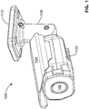
- FIG. 1 and 2 there are respectively shown a perspective view and a bottom plan view of a security camera 100 having dual communications ports, a mounting arm 108, and an attachment plate 110, according to one embodiment.
- the mounting arm 108 and attachment plate 110 are collectively the "attachment assembly" of the camera.
- the camera 100 includes and is housed within a camera body 102 that has an aperture 106 to permit light to enter the camera body 102.
- a lens (not shown) is mounted to the camera body 102 and is positioned to refract the light entering the camera body 102 through the aperture 106.
- the lens is contained within the camera body 102; however, in alternative embodiments (not depicted), the lens may be mounted to the exterior of the camera body 102.
- a hood 104 Attached to the left and right sides of the camera body 102 and extending along the top of the camera body 102 is a hood 104 that overhangs the front of the camera body 102.
- the rear of the camera body 102 is attached to the mounting arm 108, which connects the camera body 102 to the attachment plate 110 that is affixed to the mounting surface.
- a configuration panel 202 On the underside of the camera body 102 is a configuration panel 202 that has on it a secondary communication port in the form of a configuration Ethernet port 204b, a connection status LED 206, and a link LED 208, which are discussed in more detail below.
- a serial number tag 210 On the attachment plate 110 are a serial number tag 210 that identifies the camera 100 and an access port (not shown) on the surface of the attachment plate 110 that is adjacent the mounting surface when the camera 100 is mounted.
- a primary communication port in the form of a primary Ethernet port 204a (shown in Figure 3 ) is accessible through the access port and is connected to the network during camera installation.
- the Ethernet port 204a is on one side of the mounting surface when the camera body 102 is mounted (e.g.: behind a wall) whereas the configuration Ethernet port 204b and the lens are on an opposing side of the mounting surface when the camera body 102 is mounted (e.g.: in front of the wall).
- the configuration Ethernet port 204b is consequently easily accessible by the technician even after the camera 100 has been mounted to the mounting surface, whereas the access port is not.
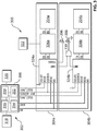
- FIG. 3 there is shown a block diagram 300 of an imager 318, control and processing circuitry 302, and communication circuitry 304a,304b housed within the camera body 102.
- the imager 318 is positioned to receive the light refracted by the lens and to output a signal to the control and processing circuitry 302, which in Figure 3 is a system on chip (SoC) 308 and a computer readable medium 320 such as non-volatile memory storing statements and instructions for the SoC 308 to perform.
- Exemplary statements and instructions include a method 400 for switching between the ports 204a,b of the camera 100 as shown in Figure 4 and discussed in more detail below.
- the SoC 308 includes a processor 310 that is communicatively coupled to each of the other components of the SoC 308: an image signal processor (ISP) 316, a media access controller (MAC) 314, and input/output control circuitry in the form of general purpose input/output (GPIO) lines 312.
- the processor 310 is also communicatively coupled to the computer readable medium 320.
- the primary communication circuitry 304a includes a primary Ethernet physical layer IC (an Ethernet physical layer IC is hereinafter referred to as a "PHY”) 324a that is communicatively coupled using transmit and receive lines to the primary Ethernet port 204a via Ethernet magnetics 326a.
- a primary Ethernet physical layer IC an Ethernet physical layer IC is hereinafter referred to as a "PHY”
- Ethernet magnetics 326a Electrically coupled to the Ethernet magnetics 326a is a DC to DC converter 322 that receives power from the network when the camera is connected to the network via the primary Ethernet port 204a; this power is used to power the camera 100 using power over Ethernet (PoE) technology.
- the primary PHY 324a is connected to the MAC 314 via the MDIO and MII buses.
- the secondary communication circuitry 304b includes a secondary PHY 324b that is communicatively coupled using transmit and receive lines to the configuration Ethernet port 204b via Ethernet magnetics 326b.
- the secondary PHY 324b is also connected to the MAC 314 via the MDIO and Mil buses.
- each of the Ethernet ports 204a,b is an RJ-45 connector and each of the PHYs 324a,b is a BroadcomTM BCM5421 10/100BaseT (Fast) Ethernet physical layer IC.
- One of the GPIO lines 312, labeled RESET_PHY1 in Figure 3 is connected to a reset pin on the primary PHY 324a while another of the GPIO lines 312, labeled RESET_PHY2 in Figure 3 , is connected to a reset pin on the secondary PHY 324b.
- the SoC 308 is accordingly able to independently reset each of the PHYs 324a,b.
- Another of the GPIO lines 312, labeled PHY_ADDRESS in Figure 3 is connected to an MDIO address select pin on each of the PHYs 324a,b.
- the SoC 308 can assign a separate MDIO address to each of the PHYs 324a,b, which is done to allow both of the PHYs 324a,b to communicate on the shared MDIO bus. This procedure is performed during system initialization.
- Each of the PHYs 324a,b also has an isolate pin that is pin strapped high.
- the PHYs 324a,b consequently boot up in "super isolated” mode in which each of the PHYs 324a,b ignores any input it receives from the Ethernet ports 204a,b and their outputs that are connected to the Mil bus are set to a high impedance state.
- the SoC 308 can use the MDIO bus to configure the PHYs 324a,b to transition to "isolated" mode in which the PHYs 324a,b are able to detect whether the ports 204a,b are coupled to an active link but its outputs that are connected to the MII bus are still set to a high impedance state, and to exit isolated mode and enter an active mode in which the PHYs 324a,b are able to transmit data over the MII bus.
- being coupled to an active link refers to the PHYs 324a,b being coupled to an active Ethernet connection via the ports 204a,b. More generally, being coupled to an active link refers to the primary and secondary communication circuitry being coupled, via the primary and secondary communication ports, respectively, to an active connection that communicates using a protocol that the primary and secondary communication circuitry is designed to use.
- Each of the PHYs 324a,b has a "link" pin that is low when the PHYs 324a,b do not detect an active link and high when they do.
- the link pins from the PHYs 324a,b are logically ORed together with the result output to the link LED 208; the link LED 208 accordingly indicates whether either of the PHYs 324a,b is coupled to an active link.
- the primary PHY 324a also has a "status" pin that the SoC 308 controls via the MDIO bus. The status pin is connected to the status LED 206, which accordingly shows the status as determined by the SoC 308.
- the SoC 308 monitors the configuration Ethernet port 204b to detect when it is coupled to an active link. When it is coupled to an active link, such as when the technician connects a video terminal to it to focus and aim the camera 100 during installation, the SoC 308 then sends the digital communication signal, which includes the digital video information derived from the light incident on the imager 318, to the configuration Ethernet port 204b.
- the SoC 308 ceases sending the digital communication signal to the primary Ethernet port 204a before sending the signal to the configuration Ethernet port 204b.
- the primary PHY 324a is referred to as PHY1
- the secondary PHY 324b is referred to as PHY2.
- the camera 100 boots up.
- the PHYs 324a,b are pin strapped to boot up in super isolated mode.
- the SoC 308 sets both of the PHYs 324a,b to isolated mode by issuing a command over the MDIO bus.
- the SoC 308 takes both of the PHYs 324a,b out of super isolated mode. While in the depicted embodiment the PHYs 324a,b boot up in super isolated mode, in alternative embodiments (not depicted) the PHYs 324a,b may boot up in isolated mode.
- the SoC 308 then takes the primary PHY 324a out of isolated mode at block 408, which is tantamount to setting the primary PHY 324a to active mode.
- the SoC 308 then initializes drivers and sets the variable ActivePHY, which the SoC 308 uses to store which of the PHYs 324a,b is currently in active mode, to the primary PHY 324a at block 410.
- the SoC 308 also initializes a variable, timeout, to invalid. As discussed in more detail below the timeout variable is used to determine when to send messages from the physical layer to the application layer.
- Blocks 404 to 410 represent the initialization phase of the method 400.
- the SoC 308 sleeps for N ms, which in the depicted embodiment is 500 ms.
- the SoC 308 determines whether timeout is valid. The first time the SoC 308 performs the method 400 timeout is invalid, and the SoC 308 proceeds to block 416 where it determines whether the configuration Ethernet port 204b is coupled to an active link, which the SoC 308 can monitor via the MDIO bus. If no, then the SoC 308 determines that the technician has not connected a video terminal to the configuration Ethernet port 204b, and the SoC 308 proceeds to block 418 where it sets a variable OldPHY to represent the secondary PHY 324b and sets a variable NewPHY to represent the primary PHY 324a.
- the SoC 308 then proceeds to block 420 where it determines whether the PHY 324a,b represented by NewPHY is the ActivePHY. In this case, as NewPHY and ActivePHY are both the primary PHY 324a, the answer is yes and the SoC 308 returns to block 412 where it loops through blocks 412 to 420 until the technician couples the configuration Ethernet port 204b to an active link.
- the secondary PHY 324b detects the active link and reports this to the SoC 308 via the MDIO bus.
- the SoC 308 arrives at block 416 it detects the active link and proceeds to block 422 where OldPHY is set to the primary PHY 324a and NewPHY is set to the secondary PHY 324b.
- the SoC 308 determines that ActivePHY is not NewPHY, and consequently proceeds to block 424 where it stops OldPHY (the primary PHY 324a) and sets it to isolated mode via the MDIO bus (block 426).
- the SoC 308 notifies the application layer that the Ethernet link is down at block 428.
- the application software running on the camera 100 accordingly believes that the Ethernet connection has been lost and can react accordingly as the physical layer transitions from the primary PHY 324a to the secondary PHY 324b.
- the SoC 308 takes NewPHY (the secondary PHY 324b) out of isolated mode, then sets ActivePHY to represent the secondary PHY 324b (block 432), and then starts using the secondary PHY 324b (block 434).
- the SoC 308 then proceeds to block 436 where it sets timeout to a valid value of the current time + M, where in the depicted embodiment M is 2,000 ms. After setting timeout the SoC 308 returns to block 412.
- the SoC 308 then loops through blocks 412, 414, and 438 three times until on the fourth time, the SoC 308 at block 438 determines that the current time equals timeout and proceeds to block 440 where it resets timeout to invalid instead of proceeding directly back to block 412. After block 440 the SoC 308 proceeds to block 442 where it notifies the application layer that the active link has returned, and then proceeds back to block 412.
- the application layer is able to function without knowledge of the dual ports 204a,b and without knowledge that what it perceives as a loss and return of the active link on one port is actually a transition from the primary PHY 324a to the secondary PHY 324b.
- the application layer may be programmed with knowledge that the camera 100 has two ports 204a,b, and may be able to handle the transition between the two ports 204a,b without the physical layer simulating a lost link as described above.
- the SoC 308 After returning to block 412, the SoC 308 loops between blocks 412 and 420 until the technician removes the active link from the configuration Ethernet port 204b by, for example, unplugging the Ethernet cable from the configuration Ethernet port 324b.
- the secondary PHY 324b detects the termination of the active link and reports this to the SoC 308 via the MDIO bus. The next time the SoC 308 arrives at block 416 it detects the lack of an active link and proceeds to block 418 where OldPHY is set to the secondary PHY 324b and NewPHY is set to the primary PHY 324a. At block 420, the SoC 308 determines that ActivePHY is not NewPHY, and consequently proceeds to block 424 where it stops OldPHY (the secondary PHY 324b) and sets it to isolated mode (block 426). The SoC 308 notifies the application layer that the Ethernet link is down at block 428.
- the SoC 308 takes NewPHY (the primary PHY 324a) out of isolated mode, then sets ActivePHY to represent the primary PHY 324a (block 432), and then starts using the primary PHY 324a (block 434).
- the SoC 308 then proceeds to block 436 where it sets timeout to a valid value of the current time + M, where in the depicted embodiment M is 2,000 ms.
- the SoC 308 returns to block 412 where the SoC 308 will wait for 2,000 ms before it notifies the application layer that the active link has returned.
- the SoC 308 then returns to block 412 where it loops between blocks 412 and 420 until the configuration Ethernet port 204b is used again.
- the primary Ethernet port 204a is coupled to an active link before, during, and after the configuration Ethernet port 204b is coupled to an active link
- the technician may use the configuration Ethernet port 204b prior to connecting the primary Ethernet port 204a to the network, or the network may be offline while the configuration Ethernet port 204b is being used.
- the PHYs 324a,b share the MII and MDIO buses and are thereby coupled to the same MAC 314.
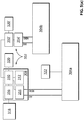
- the control and processing circuitry 302 is as shown in Figure 3 except it also includes an additional processor 310', an additional MAC 314' communicatively coupled to the processor 310', and an additional computer readable medium 320'communicatively coupled to the processor 310'.
- the additional processor 310' is connected to the processor 310 shown in Figure 3 .
- the primary PHY 324a (not expressly shown in Figure 5(a) , but part of the primary communication circuitry 304a) is coupled to the MII and MDIO buses of one of the MACs 314 while the secondary PHY 324b (not expressly shown in Figure 5(a) , but part of the secondary communication circuitry 304b) is coupled to the MII and MDIO buses of the other MAC 314'.
- the PHYs 324a,b are reset in conjunction with a system-wide reset as opposed to individually by the processors 310,310'. Because the PHYs 324a,b do not share MDIO or MII buses the address pins of the PHYs 324a,b are unused.
- the imager 318 is connected to the ISP 316, which communicates with one of the processors 310 and the DC to DC converter 322 is connected to the primary communication circuitry 304a to power the camera 100.
- the two processors 310,310' communicate with each other to send the digital communication signal to one or both of the ports 204a,b at any given time.
- control and processing circuitry 302 has two MACs 314,314' but these are either incorporated into the SoC 308 or, if not part of the SoC 308 are nonetheless controlled by the same processor 310.
- Figure 5(b) shows an embodiment in which the two MACs 314,314' are integrated into the SoC 308; the control and processing circuitry 302 is otherwise the same as that shown in Figure 3 .
- each of the PHYs 324a is connected to one of the MACs 314,314' via the MDIO bus and MII bus of that MAC 314,314'.
- the PHYs 324a,b are reset in conjunction with a system-wide reset as opposed to individually by the GPIO lines 312. Also as in Figure 5(a) , because each of the PHYs 324a,b is connected to its own MAC 314,314', the address pins of the PHYs 324a,b are left unused. As in Figures 3 and 5(a) the DC to DC converter 322 is connected to the primary communication circuitry 304a to power the camera 100.
- control and processing circuitry 302 includes a hub 502 or switch 503 interposed between the MAC 314 and the PHYs 324a,b. Additionally, the PHYs 324a,b are reset in conjunction with a system-wide reset as opposed to individually by the GIPO lines 312.
- the control and processing circuitry 302 is otherwise identical to that shown in Figure 3 , and the PHYs 324a,b are connected to the same MAC 314 via the hub 502 or switch 503.
- the hub 502 duplicates all packets sent from the MAC 314 to the PHYs 324a,b so each of the PHYs 324a,b receives the same digital communication signal from the SoC 308.
- the hub 502 analogously serializes all packets sent from either of the PHYs 324a,b to the MAC 314.
- the hub 502 may be implemented using, for example, an FPGA or as an integrated circuit.
- the SoC 308 does not notify the application layer that the link is up or down (blocks 442 and 428) as the SoC 308 is in continuous communication with the switch or hub.
- the DC to DC converter 322 is connected to the primary communication circuitry 304a to power the camera 100.
- the SoC 308 detects whether the configuration Ethernet port 204b is coupled to the active link, and sends the digital communication signal only to the configuration Ethernet port 204b and only when the configuration Ethernet port 204b is coupled to the active link. In alternative embodiments (not shown) this need not be the case.
- the SoC 308 may simultaneously send the digital communication signal to both ports 204a,b at all times, as described in the embodiment above using the hub, or only when the configuration Ethernet port 204b is coupled to the active link.
- the SoC 308 may always send the digital communication signal to the configuration Ethernet port 204b regardless of whether the configuration Ethernet port 204b is coupled to the active link.
- the digital communication signal may be separately sent to the primary Ethernet port 204a or to the configuration Ethernet port 204b.
- the camera 100 is shown as a bullet camera, in alternative embodiments (not depicted) different types of cameras, such as dome cameras, may be used.
- the SoC may instead be, for example, a microprocessor, microcontroller, programmable logic controller, field programmable gate array, or an application-specific integrated circuit.
- computer readable media are non-transitory and include disc-based media such as CD-ROMs and DVDs, magnetic media such as hard drives and other forms of magnetic disk storage, and semiconductor based media such as flash media, random access memory, and read only memory.
- Figures 4(a) and (b) depict a flowchart of an exemplary embodiment of a method. Some of the blocks illustrated in the flowchart may be performed in an order other than that which is described. Also, it should be appreciated that not all of the blocks described in the flowchart are required to be performed, that additional blocks may be added, and that some of the illustrated blocks may be substituted with other blocks.
Landscapes
- Engineering & Computer Science (AREA)
- Multimedia (AREA)
- Signal Processing (AREA)
- Theoretical Computer Science (AREA)
- Human Computer Interaction (AREA)
- Physics & Mathematics (AREA)
- General Engineering & Computer Science (AREA)
- General Physics & Mathematics (AREA)
- Studio Devices (AREA)
- Camera Bodies And Camera Details Or Accessories (AREA)
- Closed-Circuit Television Systems (AREA)
Applications Claiming Priority (2)
| Application Number | Priority Date | Filing Date | Title |
|---|---|---|---|
| US201361752896P | 2013-01-15 | 2013-01-15 | |
| PCT/CA2013/050059 WO2014110653A1 (en) | 2013-01-15 | 2013-01-28 | Security camera having dual communication ports |
Publications (3)
| Publication Number | Publication Date |
|---|---|
| EP2946546A1 EP2946546A1 (en) | 2015-11-25 |
| EP2946546A4 EP2946546A4 (en) | 2016-06-22 |
| EP2946546B1 true EP2946546B1 (en) | 2018-07-11 |
Family
ID=51164838
Family Applications (1)
| Application Number | Title | Priority Date | Filing Date |
|---|---|---|---|
| EP13872115.4A Active EP2946546B1 (en) | 2013-01-15 | 2013-01-28 | Security camera having dual communication ports |
Country Status (14)
| Country | Link |
|---|---|
| US (1) | US9098108B2 (enExample) |
| EP (1) | EP2946546B1 (enExample) |
| JP (1) | JP6017705B2 (enExample) |
| KR (1) | KR101999420B1 (enExample) |
| CN (2) | CN110177195A (enExample) |
| AU (1) | AU2013374189B2 (enExample) |
| BR (1) | BR112015016695A8 (enExample) |
| CA (1) | CA2896817C (enExample) |
| IL (1) | IL239678B (enExample) |
| MX (1) | MX351852B (enExample) |
| NZ (1) | NZ709728A (enExample) |
| SG (1) | SG11201505510QA (enExample) |
| WO (1) | WO2014110653A1 (enExample) |
| ZA (1) | ZA201505780B (enExample) |
Families Citing this family (24)
| Publication number | Priority date | Publication date | Assignee | Title |
|---|---|---|---|---|
| JPH0684464B2 (ja) | 1987-11-21 | 1994-10-26 | 株式会社アサヒコーポレーション | 鋼板の剛性補強材 |
| WO2014110653A1 (en) | 2013-01-15 | 2014-07-24 | Avigilon Corporation | Security camera having dual communication ports |
| US10592727B2 (en) * | 2014-07-28 | 2020-03-17 | Centre For Development Of Advanced Computing | Apparatus for automated monitoring of facial images and a process therefor |
| JP1540708S (enExample) * | 2015-03-09 | 2015-12-28 | ||
| USD775257S1 (en) * | 2015-09-21 | 2016-12-27 | Avigilon Corporation | Shade for a camera |
| JP2019087776A (ja) * | 2017-11-01 | 2019-06-06 | 株式会社ザクティ | 据置き型カメラ装置 |
| KR102046942B1 (ko) * | 2018-01-04 | 2019-11-20 | 주식회사 위드아이앤씨 | 감시카메라 네트워크 제어 장치, 방법 및 시스템 |
| USD892895S1 (en) * | 2018-03-30 | 2020-08-11 | Hangzhou Hikvision Digital Technology Co., Ltd. | Camera |
| USD866637S1 (en) * | 2018-05-29 | 2019-11-12 | Home Tech LLC | Spotlight camera |
| USD923684S1 (en) * | 2018-12-07 | 2021-06-29 | Portable Multimedia Ltd | Camera mount |
| USD923686S1 (en) * | 2018-12-07 | 2021-06-29 | Portable Multimedia Ltd | Camera mount |
| USD923687S1 (en) * | 2018-12-07 | 2021-06-29 | Portable Multimedia Ltd | Camera mount |
| USD923685S1 (en) * | 2018-12-07 | 2021-06-29 | Portable Multimedia Ltd | Camera mount |
| USD900371S1 (en) * | 2018-12-12 | 2020-10-27 | Shenzhen Tollar Security Equipment Co., Ltd. | Combined outdoor light and solar panel |
| US11863468B2 (en) * | 2019-04-19 | 2024-01-02 | Marvell Asia Pte Ltd | Control of ethernet link-partner GPIO using OAM |
| JP1655241S (enExample) * | 2019-09-30 | 2020-03-16 | ||
| CN114338456B (zh) * | 2020-09-25 | 2024-03-22 | 浙江宇视科技有限公司 | 图像采集设备状态确定方法、装置、电子设备及介质 |
| USD1040882S1 (en) * | 2021-06-17 | 2024-09-03 | Hanwha Vision Co., Ltd. | Camera |
| CA212704S (en) * | 2021-11-19 | 2023-11-27 | Axis Ab | Monitoring camera |
| USD1048144S1 (en) * | 2021-12-14 | 2024-10-22 | Hanwha Vision Co., Ltd. | Camera |
| USD983434S1 (en) * | 2021-12-27 | 2023-04-11 | eNet Innotech (Guangzhou) Limited | Solar lamp |
| US11847071B2 (en) | 2021-12-30 | 2023-12-19 | Pure Storage, Inc. | Enabling communication between a single-port device and multiple storage system controllers |
| TWI852142B (zh) * | 2022-10-24 | 2024-08-11 | 飛捷科技股份有限公司 | 網路裝置組態辨識方法與裝置 |
| USD1077021S1 (en) * | 2023-10-13 | 2025-05-27 | Guangdong Shone Lighting Co., Ltd | Solar powered monitor |
Family Cites Families (20)
| Publication number | Priority date | Publication date | Assignee | Title |
|---|---|---|---|---|
| US6930709B1 (en) * | 1997-12-04 | 2005-08-16 | Pentax Of America, Inc. | Integrated internet/intranet camera |
| JP2000244781A (ja) * | 1999-02-22 | 2000-09-08 | Sony Corp | ドーム型ビデオカメラ装置 |
| JP2004064253A (ja) * | 2002-07-26 | 2004-02-26 | Skd Ooru:Kk | 真空雰囲気内観察装置 |
| KR100731185B1 (ko) * | 2005-05-25 | 2007-06-27 | 카시와야마 토요히테 | 감시용 무선 카메라 장치 |
| CA2616030A1 (en) * | 2005-07-20 | 2007-01-25 | Lab Partners Associates, Inc. | Wireless photographic communication system and method |
| JP2007150790A (ja) * | 2005-11-29 | 2007-06-14 | Sony Corp | 監視カメラ |
| US20070236582A1 (en) * | 2006-03-29 | 2007-10-11 | Imaging Solutions Group Of Ny, Inc. | Video camera with multiple independent outputs |
| JP4640267B2 (ja) * | 2006-06-13 | 2011-03-02 | パナソニック株式会社 | 配線器具および監視カメラ装置 |
| CN101127673A (zh) * | 2006-08-16 | 2008-02-20 | 华为技术有限公司 | 以太网自动保护倒换方法 |
| WO2008128205A1 (en) | 2007-04-13 | 2008-10-23 | Presler Ari M | Digital cinema camera system for recording, editing and visualizing images |
| JP4618291B2 (ja) * | 2007-11-30 | 2011-01-26 | ソニー株式会社 | 送信装置、受信装置および受信装置における操作情報送信方法 |
| JP4900285B2 (ja) * | 2008-03-03 | 2012-03-21 | ソニー株式会社 | 撮像装置 |
| JP2010073002A (ja) * | 2008-09-19 | 2010-04-02 | Hoya Corp | 画像処理装置およびカメラ |
| ATE527866T1 (de) * | 2008-11-06 | 2011-10-15 | Axis Ab | Gehäuse für elektronische vorrichtung |
| CN101771598B (zh) * | 2008-12-31 | 2012-01-11 | 中国航空工业第一集团公司第六三一研究所 | 一种实时以太网通信调度方法 |
| US20100289904A1 (en) * | 2009-05-15 | 2010-11-18 | Microsoft Corporation | Video capture device providing multiple resolution video feeds |
| US8241119B2 (en) * | 2010-02-10 | 2012-08-14 | Leap Forward Gaming | Candle devices for gaming machines |
| JP5566262B2 (ja) * | 2010-11-05 | 2014-08-06 | Toa株式会社 | 監視カメラ |
| JP2013182068A (ja) * | 2012-02-29 | 2013-09-12 | Fujifilm Corp | 監視カメラ及び調整用治具 |
| WO2014110653A1 (en) | 2013-01-15 | 2014-07-24 | Avigilon Corporation | Security camera having dual communication ports |
-
2013
- 2013-01-28 WO PCT/CA2013/050059 patent/WO2014110653A1/en not_active Ceased
- 2013-01-28 AU AU2013374189A patent/AU2013374189B2/en active Active
- 2013-01-28 CN CN201910553155.0A patent/CN110177195A/zh active Pending
- 2013-01-28 NZ NZ709728A patent/NZ709728A/en not_active IP Right Cessation
- 2013-01-28 CN CN201380070373.XA patent/CN105191279A/zh active Pending
- 2013-01-28 US US13/752,264 patent/US9098108B2/en active Active
- 2013-01-28 CA CA2896817A patent/CA2896817C/en active Active
- 2013-01-28 BR BR112015016695A patent/BR112015016695A8/pt not_active Application Discontinuation
- 2013-01-28 JP JP2015551937A patent/JP6017705B2/ja active Active
- 2013-01-28 MX MX2015009158A patent/MX351852B/es active IP Right Grant
- 2013-01-28 SG SG11201505510QA patent/SG11201505510QA/en unknown
- 2013-01-28 KR KR1020157022188A patent/KR101999420B1/ko active Active
- 2013-01-28 EP EP13872115.4A patent/EP2946546B1/en active Active
-
2015
- 2015-06-29 IL IL239678A patent/IL239678B/en active IP Right Grant
- 2015-08-12 ZA ZA2015/05780A patent/ZA201505780B/en unknown
Non-Patent Citations (1)
| Title |
|---|
| None * |
Also Published As
| Publication number | Publication date |
|---|---|
| CN105191279A (zh) | 2015-12-23 |
| ZA201505780B (en) | 2017-11-29 |
| MX2015009158A (es) | 2016-03-09 |
| EP2946546A4 (en) | 2016-06-22 |
| MX351852B (es) | 2017-10-31 |
| IL239678A0 (en) | 2015-08-31 |
| US9098108B2 (en) | 2015-08-04 |
| AU2013374189A1 (en) | 2015-07-23 |
| JP2016507171A (ja) | 2016-03-07 |
| NZ709728A (en) | 2016-12-23 |
| BR112015016695A8 (pt) | 2019-10-29 |
| SG11201505510QA (en) | 2015-08-28 |
| KR20150113022A (ko) | 2015-10-07 |
| US20140198208A1 (en) | 2014-07-17 |
| WO2014110653A1 (en) | 2014-07-24 |
| BR112015016695A2 (pt) | 2017-07-11 |
| IL239678B (en) | 2019-05-30 |
| CA2896817C (en) | 2018-12-11 |
| CA2896817A1 (en) | 2014-07-24 |
| JP6017705B2 (ja) | 2016-11-02 |
| CN110177195A (zh) | 2019-08-27 |
| HK1216960A1 (en) | 2016-12-09 |
| EP2946546A1 (en) | 2015-11-25 |
| AU2013374189B2 (en) | 2016-06-02 |
| KR101999420B1 (ko) | 2019-07-11 |
Similar Documents
| Publication | Publication Date | Title |
|---|---|---|
| EP2946546B1 (en) | Security camera having dual communication ports | |
| US9860189B2 (en) | Systems and methods to enable network communications for management controllers | |
| US10587535B2 (en) | Adding a network port to a network interface card via NC-SI embedded CPU | |
| US8775713B2 (en) | Multi-protocol tunneling over an I/O interconnect | |
| CN103546300B (zh) | 一种以太网供电方法和装置 | |
| CN210324188U (zh) | 一种集成电路总线iic主从竞争自动切换设备及其系统 | |
| KR20150063393A (ko) | 감시 비디오 카메라 및 비디오 카메라를 위한 보호 케이스에 전력을 공급하기 위한 시스템 및 방법 | |
| US20150156117A1 (en) | High density server system | |
| US20180239730A1 (en) | Adding a Network Port to a Network Interface Card | |
| CN107220192A (zh) | 电子设备、通道切换的控制方法及控制电路 | |
| EP2852113B1 (en) | Load sharing method and device, and single board | |
| US9070522B2 (en) | Smart wall plate and modular jacks for secure network access and/or VLAN configuration | |
| HK1216960B (en) | Security camera having dual communication ports | |
| CN102821037B (zh) | 相机位置判别装置及方法 | |
| CN105577752B (zh) | 一种用于融合架构服务器的管理系统 | |
| US20060129702A1 (en) | Multi-mode port in a network device | |
| CN110096015A (zh) | 一种适用于智能冷柜的控制系统及其控制方法 | |
| KR102829632B1 (ko) | 연선 연결에 의해 전력을 공급받는 간헐 액추에이터들 | |
| CN106708771B (zh) | 一种网络旁路装置及其处理方法 | |
| CN223141953U (zh) | 一种poe路由器及路由器系统 | |
| CN205912156U (zh) | 一种多模式混合型硬盘录像一体机 | |
| TWM542299U (zh) | 乙太網路供電系統 | |
| TWI712263B (zh) | 用於數位通訊系統之參與實體與相關通訊系統 | |
| US9990323B2 (en) | Configuring a communication interconnect for electronic devices | |
| KR200253014Y1 (ko) | 네트워킹 구축이 가능한 유에스비 허브 |
Legal Events
| Date | Code | Title | Description |
|---|---|---|---|
| PUAI | Public reference made under article 153(3) epc to a published international application that has entered the european phase |
Free format text: ORIGINAL CODE: 0009012 |
|
| 17P | Request for examination filed |
Effective date: 20150701 |
|
| AK | Designated contracting states |
Kind code of ref document: A1 Designated state(s): AL AT BE BG CH CY CZ DE DK EE ES FI FR GB GR HR HU IE IS IT LI LT LU LV MC MK MT NL NO PL PT RO RS SE SI SK SM TR |
|
| AX | Request for extension of the european patent |
Extension state: BA ME |
|
| DAX | Request for extension of the european patent (deleted) | ||
| RIC1 | Information provided on ipc code assigned before grant |
Ipc: H04N 7/18 20060101ALI20160511BHEP Ipc: G08B 13/196 20060101ALI20160511BHEP Ipc: H04N 5/232 20060101ALI20160511BHEP Ipc: H04N 5/225 20060101ALI20160511BHEP Ipc: H04N 5/228 20060101AFI20160511BHEP |
|
| A4 | Supplementary search report drawn up and despatched |
Effective date: 20160523 |
|
| REG | Reference to a national code |
Ref country code: HK Ref legal event code: DE Ref document number: 1216960 Country of ref document: HK |
|
| STAA | Information on the status of an ep patent application or granted ep patent |
Free format text: STATUS: EXAMINATION IS IN PROGRESS |
|
| 17Q | First examination report despatched |
Effective date: 20170224 |
|
| GRAP | Despatch of communication of intention to grant a patent |
Free format text: ORIGINAL CODE: EPIDOSNIGR1 |
|
| STAA | Information on the status of an ep patent application or granted ep patent |
Free format text: STATUS: GRANT OF PATENT IS INTENDED |
|
| INTG | Intention to grant announced |
Effective date: 20180314 |
|
| GRAS | Grant fee paid |
Free format text: ORIGINAL CODE: EPIDOSNIGR3 |
|
| GRAA | (expected) grant |
Free format text: ORIGINAL CODE: 0009210 |
|
| STAA | Information on the status of an ep patent application or granted ep patent |
Free format text: STATUS: THE PATENT HAS BEEN GRANTED |
|
| AK | Designated contracting states |
Kind code of ref document: B1 Designated state(s): AL AT BE BG CH CY CZ DE DK EE ES FI FR GB GR HR HU IE IS IT LI LT LU LV MC MK MT NL NO PL PT RO RS SE SI SK SM TR |
|
| REG | Reference to a national code |
Ref country code: GB Ref legal event code: FG4D |
|
| REG | Reference to a national code |
Ref country code: CH Ref legal event code: EP |
|
| REG | Reference to a national code |
Ref country code: AT Ref legal event code: REF Ref document number: 1018158 Country of ref document: AT Kind code of ref document: T Effective date: 20180715 |
|
| REG | Reference to a national code |
Ref country code: IE Ref legal event code: FG4D |
|
| REG | Reference to a national code |
Ref country code: DE Ref legal event code: R096 Ref document number: 602013040281 Country of ref document: DE |
|
| REG | Reference to a national code |
Ref country code: SE Ref legal event code: TRGR |
|
| REG | Reference to a national code |
Ref country code: NL Ref legal event code: MP Effective date: 20180711 |
|
| REG | Reference to a national code |
Ref country code: LT Ref legal event code: MG4D |
|
| REG | Reference to a national code |
Ref country code: AT Ref legal event code: MK05 Ref document number: 1018158 Country of ref document: AT Kind code of ref document: T Effective date: 20180711 |
|
| PG25 | Lapsed in a contracting state [announced via postgrant information from national office to epo] |
Ref country code: NL Free format text: LAPSE BECAUSE OF FAILURE TO SUBMIT A TRANSLATION OF THE DESCRIPTION OR TO PAY THE FEE WITHIN THE PRESCRIBED TIME-LIMIT Effective date: 20180711 |
|
| PG25 | Lapsed in a contracting state [announced via postgrant information from national office to epo] |
Ref country code: FI Free format text: LAPSE BECAUSE OF FAILURE TO SUBMIT A TRANSLATION OF THE DESCRIPTION OR TO PAY THE FEE WITHIN THE PRESCRIBED TIME-LIMIT Effective date: 20180711 Ref country code: NO Free format text: LAPSE BECAUSE OF FAILURE TO SUBMIT A TRANSLATION OF THE DESCRIPTION OR TO PAY THE FEE WITHIN THE PRESCRIBED TIME-LIMIT Effective date: 20181011 Ref country code: GR Free format text: LAPSE BECAUSE OF FAILURE TO SUBMIT A TRANSLATION OF THE DESCRIPTION OR TO PAY THE FEE WITHIN THE PRESCRIBED TIME-LIMIT Effective date: 20181012 Ref country code: AT Free format text: LAPSE BECAUSE OF FAILURE TO SUBMIT A TRANSLATION OF THE DESCRIPTION OR TO PAY THE FEE WITHIN THE PRESCRIBED TIME-LIMIT Effective date: 20180711 Ref country code: IS Free format text: LAPSE BECAUSE OF FAILURE TO SUBMIT A TRANSLATION OF THE DESCRIPTION OR TO PAY THE FEE WITHIN THE PRESCRIBED TIME-LIMIT Effective date: 20181111 Ref country code: RS Free format text: LAPSE BECAUSE OF FAILURE TO SUBMIT A TRANSLATION OF THE DESCRIPTION OR TO PAY THE FEE WITHIN THE PRESCRIBED TIME-LIMIT Effective date: 20180711 Ref country code: LT Free format text: LAPSE BECAUSE OF FAILURE TO SUBMIT A TRANSLATION OF THE DESCRIPTION OR TO PAY THE FEE WITHIN THE PRESCRIBED TIME-LIMIT Effective date: 20180711 Ref country code: BG Free format text: LAPSE BECAUSE OF FAILURE TO SUBMIT A TRANSLATION OF THE DESCRIPTION OR TO PAY THE FEE WITHIN THE PRESCRIBED TIME-LIMIT Effective date: 20181011 Ref country code: PL Free format text: LAPSE BECAUSE OF FAILURE TO SUBMIT A TRANSLATION OF THE DESCRIPTION OR TO PAY THE FEE WITHIN THE PRESCRIBED TIME-LIMIT Effective date: 20180711 |
|
| PG25 | Lapsed in a contracting state [announced via postgrant information from national office to epo] |
Ref country code: AL Free format text: LAPSE BECAUSE OF FAILURE TO SUBMIT A TRANSLATION OF THE DESCRIPTION OR TO PAY THE FEE WITHIN THE PRESCRIBED TIME-LIMIT Effective date: 20180711 Ref country code: HR Free format text: LAPSE BECAUSE OF FAILURE TO SUBMIT A TRANSLATION OF THE DESCRIPTION OR TO PAY THE FEE WITHIN THE PRESCRIBED TIME-LIMIT Effective date: 20180711 Ref country code: LV Free format text: LAPSE BECAUSE OF FAILURE TO SUBMIT A TRANSLATION OF THE DESCRIPTION OR TO PAY THE FEE WITHIN THE PRESCRIBED TIME-LIMIT Effective date: 20180711 Ref country code: ES Free format text: LAPSE BECAUSE OF FAILURE TO SUBMIT A TRANSLATION OF THE DESCRIPTION OR TO PAY THE FEE WITHIN THE PRESCRIBED TIME-LIMIT Effective date: 20180711 |
|
| REG | Reference to a national code |
Ref country code: DE Ref legal event code: R097 Ref document number: 602013040281 Country of ref document: DE |
|
| PG25 | Lapsed in a contracting state [announced via postgrant information from national office to epo] |
Ref country code: IT Free format text: LAPSE BECAUSE OF FAILURE TO SUBMIT A TRANSLATION OF THE DESCRIPTION OR TO PAY THE FEE WITHIN THE PRESCRIBED TIME-LIMIT Effective date: 20180711 Ref country code: RO Free format text: LAPSE BECAUSE OF FAILURE TO SUBMIT A TRANSLATION OF THE DESCRIPTION OR TO PAY THE FEE WITHIN THE PRESCRIBED TIME-LIMIT Effective date: 20180711 Ref country code: CZ Free format text: LAPSE BECAUSE OF FAILURE TO SUBMIT A TRANSLATION OF THE DESCRIPTION OR TO PAY THE FEE WITHIN THE PRESCRIBED TIME-LIMIT Effective date: 20180711 Ref country code: EE Free format text: LAPSE BECAUSE OF FAILURE TO SUBMIT A TRANSLATION OF THE DESCRIPTION OR TO PAY THE FEE WITHIN THE PRESCRIBED TIME-LIMIT Effective date: 20180711 |
|
| PLBE | No opposition filed within time limit |
Free format text: ORIGINAL CODE: 0009261 |
|
| STAA | Information on the status of an ep patent application or granted ep patent |
Free format text: STATUS: NO OPPOSITION FILED WITHIN TIME LIMIT |
|
| PG25 | Lapsed in a contracting state [announced via postgrant information from national office to epo] |
Ref country code: SM Free format text: LAPSE BECAUSE OF FAILURE TO SUBMIT A TRANSLATION OF THE DESCRIPTION OR TO PAY THE FEE WITHIN THE PRESCRIBED TIME-LIMIT Effective date: 20180711 Ref country code: DK Free format text: LAPSE BECAUSE OF FAILURE TO SUBMIT A TRANSLATION OF THE DESCRIPTION OR TO PAY THE FEE WITHIN THE PRESCRIBED TIME-LIMIT Effective date: 20180711 Ref country code: SK Free format text: LAPSE BECAUSE OF FAILURE TO SUBMIT A TRANSLATION OF THE DESCRIPTION OR TO PAY THE FEE WITHIN THE PRESCRIBED TIME-LIMIT Effective date: 20180711 |
|
| 26N | No opposition filed |
Effective date: 20190412 |
|
| PG25 | Lapsed in a contracting state [announced via postgrant information from national office to epo] |
Ref country code: SI Free format text: LAPSE BECAUSE OF FAILURE TO SUBMIT A TRANSLATION OF THE DESCRIPTION OR TO PAY THE FEE WITHIN THE PRESCRIBED TIME-LIMIT Effective date: 20180711 Ref country code: MC Free format text: LAPSE BECAUSE OF FAILURE TO SUBMIT A TRANSLATION OF THE DESCRIPTION OR TO PAY THE FEE WITHIN THE PRESCRIBED TIME-LIMIT Effective date: 20180711 |
|
| REG | Reference to a national code |
Ref country code: CH Ref legal event code: PL |
|
| PG25 | Lapsed in a contracting state [announced via postgrant information from national office to epo] |
Ref country code: LU Free format text: LAPSE BECAUSE OF NON-PAYMENT OF DUE FEES Effective date: 20190128 |
|
| REG | Reference to a national code |
Ref country code: BE Ref legal event code: MM Effective date: 20190131 |
|
| REG | Reference to a national code |
Ref country code: IE Ref legal event code: MM4A |
|
| PG25 | Lapsed in a contracting state [announced via postgrant information from national office to epo] |
Ref country code: BE Free format text: LAPSE BECAUSE OF NON-PAYMENT OF DUE FEES Effective date: 20190131 |
|
| PG25 | Lapsed in a contracting state [announced via postgrant information from national office to epo] |
Ref country code: LI Free format text: LAPSE BECAUSE OF NON-PAYMENT OF DUE FEES Effective date: 20190131 Ref country code: CH Free format text: LAPSE BECAUSE OF NON-PAYMENT OF DUE FEES Effective date: 20190131 |
|
| PG25 | Lapsed in a contracting state [announced via postgrant information from national office to epo] |
Ref country code: IE Free format text: LAPSE BECAUSE OF NON-PAYMENT OF DUE FEES Effective date: 20190128 |
|
| PG25 | Lapsed in a contracting state [announced via postgrant information from national office to epo] |
Ref country code: TR Free format text: LAPSE BECAUSE OF FAILURE TO SUBMIT A TRANSLATION OF THE DESCRIPTION OR TO PAY THE FEE WITHIN THE PRESCRIBED TIME-LIMIT Effective date: 20180711 |
|
| PG25 | Lapsed in a contracting state [announced via postgrant information from national office to epo] |
Ref country code: MT Free format text: LAPSE BECAUSE OF NON-PAYMENT OF DUE FEES Effective date: 20190128 Ref country code: PT Free format text: LAPSE BECAUSE OF FAILURE TO SUBMIT A TRANSLATION OF THE DESCRIPTION OR TO PAY THE FEE WITHIN THE PRESCRIBED TIME-LIMIT Effective date: 20181111 |
|
| REG | Reference to a national code |
Ref country code: DE Ref legal event code: R082 Ref document number: 602013040281 Country of ref document: DE Representative=s name: SCHUMACHER & WILLSAU PATENTANWALTSGESELLSCHAFT, DE |
|
| PG25 | Lapsed in a contracting state [announced via postgrant information from national office to epo] |
Ref country code: CY Free format text: LAPSE BECAUSE OF FAILURE TO SUBMIT A TRANSLATION OF THE DESCRIPTION OR TO PAY THE FEE WITHIN THE PRESCRIBED TIME-LIMIT Effective date: 20180711 |
|
| PG25 | Lapsed in a contracting state [announced via postgrant information from national office to epo] |
Ref country code: HU Free format text: LAPSE BECAUSE OF FAILURE TO SUBMIT A TRANSLATION OF THE DESCRIPTION OR TO PAY THE FEE WITHIN THE PRESCRIBED TIME-LIMIT; INVALID AB INITIO Effective date: 20130128 |
|
| PG25 | Lapsed in a contracting state [announced via postgrant information from national office to epo] |
Ref country code: MK Free format text: LAPSE BECAUSE OF FAILURE TO SUBMIT A TRANSLATION OF THE DESCRIPTION OR TO PAY THE FEE WITHIN THE PRESCRIBED TIME-LIMIT Effective date: 20180711 |
|
| REG | Reference to a national code |
Ref country code: DE Ref legal event code: R081 Ref document number: 602013040281 Country of ref document: DE Owner name: MOTOROLA SOLUTIONS, INC., CHICAGO, US Free format text: FORMER OWNER: AVIGILON CORPORATION, VANCOUVER, BRITISH COLUMBIA, CA |
|
| REG | Reference to a national code |
Ref country code: DE Ref legal event code: R079 Ref document number: 602013040281 Country of ref document: DE Free format text: PREVIOUS MAIN CLASS: H04N0005228000 Ipc: H04N0023400000 |
|
| REG | Reference to a national code |
Ref country code: GB Ref legal event code: 732E Free format text: REGISTERED BETWEEN 20221229 AND 20230104 |
|
| P01 | Opt-out of the competence of the unified patent court (upc) registered |
Effective date: 20230529 |
|
| PGFP | Annual fee paid to national office [announced via postgrant information from national office to epo] |
Ref country code: GB Payment date: 20241219 Year of fee payment: 13 |
|
| PGFP | Annual fee paid to national office [announced via postgrant information from national office to epo] |
Ref country code: FR Payment date: 20241219 Year of fee payment: 13 |
|
| PGFP | Annual fee paid to national office [announced via postgrant information from national office to epo] |
Ref country code: SE Payment date: 20241219 Year of fee payment: 13 |
|
| PGFP | Annual fee paid to national office [announced via postgrant information from national office to epo] |
Ref country code: DE Payment date: 20241218 Year of fee payment: 13 |