EP2945563B1 - Procédé de fabrication d'un élément d'ancrage - Google Patents
Procédé de fabrication d'un élément d'ancrage Download PDFInfo
- Publication number
- EP2945563B1 EP2945563B1 EP14700853.6A EP14700853A EP2945563B1 EP 2945563 B1 EP2945563 B1 EP 2945563B1 EP 14700853 A EP14700853 A EP 14700853A EP 2945563 B1 EP2945563 B1 EP 2945563B1
- Authority
- EP
- European Patent Office
- Prior art keywords
- implant
- abutment
- anchoring element
- subregion
- muffle
- Prior art date
- Legal status (The legal status is an assumption and is not a legal conclusion. Google has not performed a legal analysis and makes no representation as to the accuracy of the status listed.)
- Active
Links
- 238000004873 anchoring Methods 0.000 title claims description 37
- 238000004519 manufacturing process Methods 0.000 title description 6
- 239000007943 implant Substances 0.000 claims description 82
- 238000000034 method Methods 0.000 claims description 46
- 239000000463 material Substances 0.000 claims description 21
- 239000004696 Poly ether ether ketone Substances 0.000 claims description 19
- 229920002530 polyetherether ketone Polymers 0.000 claims description 19
- JUPQTSLXMOCDHR-UHFFFAOYSA-N benzene-1,4-diol;bis(4-fluorophenyl)methanone Chemical compound OC1=CC=C(O)C=C1.C1=CC(F)=CC=C1C(=O)C1=CC=C(F)C=C1 JUPQTSLXMOCDHR-UHFFFAOYSA-N 0.000 claims description 18
- 229920001169 thermoplastic Polymers 0.000 claims description 18
- 238000003825 pressing Methods 0.000 claims description 14
- 239000008187 granular material Substances 0.000 claims description 13
- RTAQQCXQSZGOHL-UHFFFAOYSA-N Titanium Chemical compound [Ti] RTAQQCXQSZGOHL-UHFFFAOYSA-N 0.000 claims description 11
- 239000000919 ceramic Substances 0.000 claims description 11
- 238000007731 hot pressing Methods 0.000 claims description 11
- 239000010936 titanium Substances 0.000 claims description 11
- 229910052719 titanium Inorganic materials 0.000 claims description 10
- MCMNRKCIXSYSNV-UHFFFAOYSA-N ZrO2 Inorganic materials O=[Zr]=O MCMNRKCIXSYSNV-UHFFFAOYSA-N 0.000 claims description 9
- RVTZCBVAJQQJTK-UHFFFAOYSA-N oxygen(2-);zirconium(4+) Chemical compound [O-2].[O-2].[Zr+4] RVTZCBVAJQQJTK-UHFFFAOYSA-N 0.000 claims description 7
- 238000010438 heat treatment Methods 0.000 claims description 6
- PNEYBMLMFCGWSK-UHFFFAOYSA-N Alumina Chemical compound [O-2].[O-2].[O-2].[Al+3].[Al+3] PNEYBMLMFCGWSK-UHFFFAOYSA-N 0.000 claims description 4
- 229920000426 Microplastic Polymers 0.000 claims description 4
- 239000000654 additive Substances 0.000 claims description 4
- 230000000996 additive effect Effects 0.000 claims description 3
- 239000012815 thermoplastic material Substances 0.000 claims description 3
- 229910001069 Ti alloy Inorganic materials 0.000 claims 1
- 239000010953 base metal Substances 0.000 claims 1
- 239000004033 plastic Substances 0.000 description 13
- 229920003023 plastic Polymers 0.000 description 13
- 229920000642 polymer Polymers 0.000 description 11
- 210000000332 tooth crown Anatomy 0.000 description 9
- 239000004053 dental implant Substances 0.000 description 5
- 229910000510 noble metal Inorganic materials 0.000 description 5
- 238000001816 cooling Methods 0.000 description 4
- 238000003780 insertion Methods 0.000 description 4
- 230000037431 insertion Effects 0.000 description 4
- TWNQGVIAIRXVLR-UHFFFAOYSA-N oxo(oxoalumanyloxy)alumane Chemical compound O=[Al]O[Al]=O TWNQGVIAIRXVLR-UHFFFAOYSA-N 0.000 description 4
- 229910010293 ceramic material Inorganic materials 0.000 description 3
- 230000001055 chewing effect Effects 0.000 description 3
- 150000001875 compounds Chemical class 0.000 description 3
- 238000004026 adhesive bonding Methods 0.000 description 2
- 230000015572 biosynthetic process Effects 0.000 description 2
- 238000007906 compression Methods 0.000 description 2
- 238000010276 construction Methods 0.000 description 2
- 239000005548 dental material Substances 0.000 description 2
- 239000003814 drug Substances 0.000 description 2
- 239000000945 filler Substances 0.000 description 2
- 230000007794 irritation Effects 0.000 description 2
- 239000004416 thermosoftening plastic Substances 0.000 description 2
- 229910000831 Steel Inorganic materials 0.000 description 1
- 239000000853 adhesive Substances 0.000 description 1
- 230000001070 adhesive effect Effects 0.000 description 1
- 239000000560 biocompatible material Substances 0.000 description 1
- 230000015556 catabolic process Effects 0.000 description 1
- 230000002925 chemical effect Effects 0.000 description 1
- 230000006835 compression Effects 0.000 description 1
- 238000006731 degradation reaction Methods 0.000 description 1
- 230000001419 dependent effect Effects 0.000 description 1
- WVMPCBWWBLZKPD-UHFFFAOYSA-N dilithium oxido-[oxido(oxo)silyl]oxy-oxosilane Chemical compound [Li+].[Li+].[O-][Si](=O)O[Si]([O-])=O WVMPCBWWBLZKPD-UHFFFAOYSA-N 0.000 description 1
- 238000002474 experimental method Methods 0.000 description 1
- 210000001145 finger joint Anatomy 0.000 description 1
- PCHJSUWPFVWCPO-UHFFFAOYSA-N gold Chemical compound [Au] PCHJSUWPFVWCPO-UHFFFAOYSA-N 0.000 description 1
- 239000010931 gold Substances 0.000 description 1
- 229910052737 gold Inorganic materials 0.000 description 1
- 210000003709 heart valve Anatomy 0.000 description 1
- 229920006258 high performance thermoplastic Polymers 0.000 description 1
- 238000011540 hip replacement Methods 0.000 description 1
- 238000002347 injection Methods 0.000 description 1
- 239000007924 injection Substances 0.000 description 1
- 230000003993 interaction Effects 0.000 description 1
- 238000002844 melting Methods 0.000 description 1
- 230000008018 melting Effects 0.000 description 1
- 229910044991 metal oxide Inorganic materials 0.000 description 1
- 150000004706 metal oxides Chemical class 0.000 description 1
- 238000000465 moulding Methods 0.000 description 1
- 230000000704 physical effect Effects 0.000 description 1
- 239000010970 precious metal Substances 0.000 description 1
- 230000002787 reinforcement Effects 0.000 description 1
- 230000003763 resistance to breakage Effects 0.000 description 1
- 238000007493 shaping process Methods 0.000 description 1
- 238000005507 spraying Methods 0.000 description 1
- 239000010959 steel Substances 0.000 description 1
- GWEVSGVZZGPLCZ-UHFFFAOYSA-N titanium dioxide Inorganic materials O=[Ti]=O GWEVSGVZZGPLCZ-UHFFFAOYSA-N 0.000 description 1
Images


Classifications
-
- A—HUMAN NECESSITIES
- A61—MEDICAL OR VETERINARY SCIENCE; HYGIENE
- A61C—DENTISTRY; APPARATUS OR METHODS FOR ORAL OR DENTAL HYGIENE
- A61C13/00—Dental prostheses; Making same
-
- A—HUMAN NECESSITIES
- A61—MEDICAL OR VETERINARY SCIENCE; HYGIENE
- A61C—DENTISTRY; APPARATUS OR METHODS FOR ORAL OR DENTAL HYGIENE
- A61C13/00—Dental prostheses; Making same
- A61C13/0003—Making bridge-work, inlays, implants or the like
- A61C13/0006—Production methods
-
- A—HUMAN NECESSITIES
- A61—MEDICAL OR VETERINARY SCIENCE; HYGIENE
- A61C—DENTISTRY; APPARATUS OR METHODS FOR ORAL OR DENTAL HYGIENE
- A61C8/00—Means to be fixed to the jaw-bone for consolidating natural teeth or for fixing dental prostheses thereon; Dental implants; Implanting tools
- A61C8/0012—Means to be fixed to the jaw-bone for consolidating natural teeth or for fixing dental prostheses thereon; Dental implants; Implanting tools characterised by the material or composition, e.g. ceramics, surface layer, metal alloy
- A61C8/0016—Means to be fixed to the jaw-bone for consolidating natural teeth or for fixing dental prostheses thereon; Dental implants; Implanting tools characterised by the material or composition, e.g. ceramics, surface layer, metal alloy polymeric material
-
- A—HUMAN NECESSITIES
- A61—MEDICAL OR VETERINARY SCIENCE; HYGIENE
- A61C—DENTISTRY; APPARATUS OR METHODS FOR ORAL OR DENTAL HYGIENE
- A61C8/00—Means to be fixed to the jaw-bone for consolidating natural teeth or for fixing dental prostheses thereon; Dental implants; Implanting tools
- A61C8/0018—Means to be fixed to the jaw-bone for consolidating natural teeth or for fixing dental prostheses thereon; Dental implants; Implanting tools characterised by the shape
- A61C8/0022—Self-screwing
- A61C8/0025—Self-screwing with multiple threads
-
- A—HUMAN NECESSITIES
- A61—MEDICAL OR VETERINARY SCIENCE; HYGIENE
- A61C—DENTISTRY; APPARATUS OR METHODS FOR ORAL OR DENTAL HYGIENE
- A61C8/00—Means to be fixed to the jaw-bone for consolidating natural teeth or for fixing dental prostheses thereon; Dental implants; Implanting tools
- A61C8/0048—Connecting the upper structure to the implant, e.g. bridging bars
- A61C8/005—Connecting devices for joining an upper structure with an implant member, e.g. spacers
- A61C8/0051—Abutment monobloc with restoration
-
- B—PERFORMING OPERATIONS; TRANSPORTING
- B29—WORKING OF PLASTICS; WORKING OF SUBSTANCES IN A PLASTIC STATE IN GENERAL
- B29C—SHAPING OR JOINING OF PLASTICS; SHAPING OF MATERIAL IN A PLASTIC STATE, NOT OTHERWISE PROVIDED FOR; AFTER-TREATMENT OF THE SHAPED PRODUCTS, e.g. REPAIRING
- B29C70/00—Shaping composites, i.e. plastics material comprising reinforcements, fillers or preformed parts, e.g. inserts
- B29C70/68—Shaping composites, i.e. plastics material comprising reinforcements, fillers or preformed parts, e.g. inserts by incorporating or moulding on preformed parts, e.g. inserts or layers, e.g. foam blocks
- B29C70/681—Component parts, details or accessories; Auxiliary operations
- B29C70/682—Preformed parts characterised by their structure, e.g. form
-
- B—PERFORMING OPERATIONS; TRANSPORTING
- B29—WORKING OF PLASTICS; WORKING OF SUBSTANCES IN A PLASTIC STATE IN GENERAL
- B29C—SHAPING OR JOINING OF PLASTICS; SHAPING OF MATERIAL IN A PLASTIC STATE, NOT OTHERWISE PROVIDED FOR; AFTER-TREATMENT OF THE SHAPED PRODUCTS, e.g. REPAIRING
- B29C70/00—Shaping composites, i.e. plastics material comprising reinforcements, fillers or preformed parts, e.g. inserts
- B29C70/68—Shaping composites, i.e. plastics material comprising reinforcements, fillers or preformed parts, e.g. inserts by incorporating or moulding on preformed parts, e.g. inserts or layers, e.g. foam blocks
- B29C70/72—Encapsulating inserts having non-encapsulated projections, e.g. extremities or terminal portions of electrical components
-
- B—PERFORMING OPERATIONS; TRANSPORTING
- B29—WORKING OF PLASTICS; WORKING OF SUBSTANCES IN A PLASTIC STATE IN GENERAL
- B29K—INDEXING SCHEME ASSOCIATED WITH SUBCLASSES B29B, B29C OR B29D, RELATING TO MOULDING MATERIALS OR TO MATERIALS FOR MOULDS, REINFORCEMENTS, FILLERS OR PREFORMED PARTS, e.g. INSERTS
- B29K2071/00—Use of polyethers, e.g. PEEK, i.e. polyether-etherketone or PEK, i.e. polyetherketone or derivatives thereof, as moulding material
-
- B—PERFORMING OPERATIONS; TRANSPORTING
- B29—WORKING OF PLASTICS; WORKING OF SUBSTANCES IN A PLASTIC STATE IN GENERAL
- B29K—INDEXING SCHEME ASSOCIATED WITH SUBCLASSES B29B, B29C OR B29D, RELATING TO MOULDING MATERIALS OR TO MATERIALS FOR MOULDS, REINFORCEMENTS, FILLERS OR PREFORMED PARTS, e.g. INSERTS
- B29K2105/00—Condition, form or state of moulded material or of the material to be shaped
- B29K2105/25—Solid
- B29K2105/251—Particles, powder or granules
-
- B—PERFORMING OPERATIONS; TRANSPORTING
- B29—WORKING OF PLASTICS; WORKING OF SUBSTANCES IN A PLASTIC STATE IN GENERAL
- B29K—INDEXING SCHEME ASSOCIATED WITH SUBCLASSES B29B, B29C OR B29D, RELATING TO MOULDING MATERIALS OR TO MATERIALS FOR MOULDS, REINFORCEMENTS, FILLERS OR PREFORMED PARTS, e.g. INSERTS
- B29K2509/00—Use of inorganic materials not provided for in groups B29K2503/00 - B29K2507/00, as filler
- B29K2509/02—Ceramics
-
- B—PERFORMING OPERATIONS; TRANSPORTING
- B29—WORKING OF PLASTICS; WORKING OF SUBSTANCES IN A PLASTIC STATE IN GENERAL
- B29K—INDEXING SCHEME ASSOCIATED WITH SUBCLASSES B29B, B29C OR B29D, RELATING TO MOULDING MATERIALS OR TO MATERIALS FOR MOULDS, REINFORCEMENTS, FILLERS OR PREFORMED PARTS, e.g. INSERTS
- B29K2705/00—Use of metals, their alloys or their compounds, for preformed parts, e.g. for inserts
- B29K2705/08—Transition metals
-
- B—PERFORMING OPERATIONS; TRANSPORTING
- B29—WORKING OF PLASTICS; WORKING OF SUBSTANCES IN A PLASTIC STATE IN GENERAL
- B29K—INDEXING SCHEME ASSOCIATED WITH SUBCLASSES B29B, B29C OR B29D, RELATING TO MOULDING MATERIALS OR TO MATERIALS FOR MOULDS, REINFORCEMENTS, FILLERS OR PREFORMED PARTS, e.g. INSERTS
- B29K2709/00—Use of inorganic materials not provided for in groups B29K2703/00 - B29K2707/00, for preformed parts, e.g. for inserts
- B29K2709/02—Ceramics
-
- B—PERFORMING OPERATIONS; TRANSPORTING
- B29—WORKING OF PLASTICS; WORKING OF SUBSTANCES IN A PLASTIC STATE IN GENERAL
- B29L—INDEXING SCHEME ASSOCIATED WITH SUBCLASS B29C, RELATING TO PARTICULAR ARTICLES
- B29L2031/00—Other particular articles
- B29L2031/753—Medical equipment; Accessories therefor
- B29L2031/7532—Artificial members, protheses
- B29L2031/7536—Artificial teeth
Definitions
- the invention relates to a method for overpressing an abutment or an abutment portion of an implant with a dental prosthetic arrangement.
- Abutments are well known in the art and are used in a variety of dental prosthetics.
- An abutment is a structural element used to fix crowns or dental bridges in dentistry.
- abutments are used as a primary or secondary support of ridge-like or telescopic dental prosthetic arrangements.
- An abutment usually has a metallic pin which is provided, for example, in combination with an implant as anchoring point in a jawbone. For example, a crown is attached to the side opposite the anchoring point.
- Known abutments are usually made of titanium.
- Implants are also known from the general state of the art. These have a screw connection on a side facing the jawbone, so that the implant can be anchored in the jaw. On the opposite side, for example, a tooth crown or the like is applied.
- a prefabricated dental implant comprising a prefabricated abutment having a subgingival end anchored in the implant and an opposite end, the opposite end permanently connected to a fusible dental material and the abutment made of a different material than the fusible dental material ,
- a dental implant consisting of a ceramic material is described with an implant body for anchoring in a jawbone and implantable into a holding receptacle of the implant body and fixable implant post, which protruding from the implant body support portion for fixing a dental prosthesis is formed and its fixable in the holding receptacle holding section and this Holding receptacle each tapered conically in each case at least in a partial region in the insertion direction.
- a method for producing a dental restoration includes attaching an abutment to an implant in the mouth of a patient and scanning at least a portion of the abutment in the patient's mouth to capture a digital surface representation to create a three-dimensional digital model of the digital surface representation, and forming a restoration from the three-dimensional digital model.
- the production of temporary crowns is described in order to temporarily restore dental implants.
- the prefabricated provisional crowns are at the gingival portion of the stop device of a dental implant or collar of a dental implant customized.
- the prefabricated temporary implant crown is generally designed as a hollow shell.
- the use of dental prosthetic arrangements often involves high forces in the anchoring elements, which can lead to mechanical loads, so that possibly the adhesive connections are loosened or mechanical damage can occur.
- An anchoring element for a dental prosthetic arrangement is provided, which can be anchored in a first partial area in a jawbone or implant, and which is suitable for receiving or forming a dental prosthetic element in a second partial area, wherein the anchoring element between the first partial area and the second Partial region has a collar projecting in the radial direction, the circumference of the At least partially enclosing anchoring element, wherein the area above the collar of the anchoring element is at least partially covered over the entire surface with a thermoplastic material.
- a retaining element is applied, which is used as a connection between the retaining pin and a dental prosthetic element, such as a prosthesis.
- a dental crown is used or can form this directly by appropriate shaping.
- the dental prosthetic element can be glued to the retaining element or connected to the abutment or implant by screws. Due to the gap-free connection between the holding element and the retaining pin, the abutment or the implant is able to absorb high forces without loosening or splintering. Consequently, high chewing forces can be absorbed.
- the arranged above the collar part of the retaining pin acts as an additional reinforcement.
- the anchoring element can comprise a retaining pin that can be inserted into an implant, which preferably has a non-rotationally symmetrical cross section, or an implant that can be anchored in a jawbone.
- the anchoring element may have a roughened surface in the second subregion.
- a roughened surface can promote the connection of the retaining element with the retaining pin or the implant by means of hot pressing.
- the roughened surface can have a grain size in the range of a few 100 .mu.m, the exact configuration depending on the materials of the abutment used.
- the holding element is made of a thermoplastic polymer, preferably made of PEEK.
- PEEK (abbreviated to polyetheretherketone) is essentially physiologically inert as a biocompatible material when used in medicine and consequently is free of irritation to the patient.
- PEEK but also other high-performance polymers, have a high load capacity with regard to chewing forces, so that fracture stabilities of up to 1000 MPa can be achieved. Consequently, this material offers much higher safety margins compared to lithium disilicate ceramics, which is particularly important for use in the posterior region.
- the retaining pin or implant is made of a non-noble metal, preferably titanium, of a ceramic, in particular aluminum oxide, or of zirconium dioxide.
- Titanium is well-suited for use in dental prosthetics in the human body.
- stress-free abutments wherein the consisting of the thermoplastic polymer retaining element and the titanium retaining pin are joined together without gaps.
- the underlying physical or chemical effect is not fully known. It is surprisingly found that the hot-pressed polymer forms a particularly stable compound with the non-precious metal, which is also free from cracks and gaps.
- the metal oxide forming on the surface of the non-noble metal forms a compound with the polymer chains of the holding element, which gives the abutment particularly powerful properties. Ceramic materials such as alumina or zirconia can also be used.
- the retaining pin or the implant on its outer side in the region of the holding element on a profiled surface.
- a profiled surface forms retentive areas, so that after a hot pressing the plastic material of the thermoplastic polymer can withdraw during cooling in these areas. This supports the full-surface, so complete coverage of the retaining pin with the thermoplastic material.
- the profiled surface may comprise a plurality of ribs arranged in parallel in the axial direction, preferably with a triangular cross-section.
- the thermoplastic polymer may be formed in the second partial region, which forms a holding element, so that the anchoring element can be used as an abutment.
- thermoplastic polymer may be shaped so that a tooth crown is formed in the second portion.
- the anchoring element can be used as a one-piece, two-phase implant.
- the plastic material is provided as a high performance thermoplastic polymer, preferably PEEK.
- the retaining pin is made of a non-noble metal, preferably titanium, of a ceramic, in particular aluminum oxide, or of zirconium dioxide.
- the step of compressing the plastic material is carried out with heating in a temperature range between 240 ° C and 450 ° C, preferably in the range between 380 ° C and 400 ° C.
- a preheating step preferably between 600 ° C and 650 ° C, is performed prior to the step of filling the muffle mold with the plastic material.
- the step of pressing is carried out under vacuum.
- a tooth prosthetic arrangement which has an anchoring element described above, wherein the holding element of the abutment or of the implant serves as a support structure.
- a crown, bridge, or ridge-type tooth replacement may be associated with one or more abutments.
- connection with the one or more abutments can be produced by gluing or screwing.
- the high performance polymer may comprise PEEK.
- the high performance polymer may also be mixed with a ceramic additive.
- Fig. 1 (A) shows a retaining pin HS as an anchoring element for an abutment AB in a perspective side view.
- the retaining pin HS has a radially projecting collar KR, which at least partially surrounds the circumference of the retaining pin HS.
- a first portion TB1 is formed, which is anchored in an in Fig. 1 (A) Not shown implant is used.
- Above the collar KR is the second portion TB2.
- the retaining pin HS has a profiling on its outside. This is in Fig. 1 (A) is shown as an array of a plurality of axially parallel ribs RI surrounding the periphery of the retaining pin HS in the second portion TB2.
- the ribs RI have, for example, a triangular cross-section, wherein other embodiments are also possible.
- Fig. 2 is the holding pin HS off Fig. 1 (A) shown in a cross-sectional view.
- the cross-sectional view of Fig. 2 corresponds to a view from the end of the second portion TB2 ago. How one Fig. 2 can be taken as the diameter of the ribs RI is smaller than that of the collar KR.
- the ribs RI are designed in a plurality of areas BE1, BE2, BE3 and BE4 with a reduced diameter, so that the overall result is a non-rotationally symmetrical cross section of the retaining pin HS.
- the non-rotationally symmetrical cross section of the retaining pin HS can be achieved in a variety of ways, for example, with a different number of areas with reduced diameter, but also by means of areas with increased diameter or other positioning of these areas.
- the abutment AB has a passage DF which completely penetrates the abutment AB along its longitudinal axis.
- the bushing DF can be used to lock the retaining pin HS after insertion into an implant, for example by means of a screw connection.
- Fig. 1 (B) shows an implant IM as anchoring element VE in a perspective side view.
- the implant IM also has the radially projecting collar KR, which at least partially surrounds the circumference of the retaining pin HS.
- the helical implant is formed in the first portion TB1, which is anchored in an in Fig. 1 (B) Jawbone, not shown, serves.
- the collar KR Above the collar KR is the second portion TB2.
- the retaining pin HS has the profiling on its outside. This is in Fig. 1 (B) again shown as an arrangement of a plurality of axially parallel ribs RI which surround the circumference of the retaining pin HS in the second portion TB2.
- abutment AB is shown starting from the retaining pin HS according to Fig. 1 (A) and 2 was further developed to form a so-called hybrid abutment.
- Hybrid abutments have, in addition to the retaining pin HS an additional element that can be used as the basis for a dental prosthetic arrangement, such as a crown.
- a holding element HE is mounted above the collar KR, which partially covers the collar KR and the retaining pin HS.
- the holding element HE is made of a thermoplastic polymer, in particular PEEK.
- the holding element HE covers in particular the grooves RI, which serve as retentive areas, so that after a hot pressing the plastic material of the thermoplastic polymer can withdraw during cooling in these areas.
- the retaining pin HS is made of a non-noble metal, in particular titanium, of a ceramic, in particular aluminum oxide, or of zirconium dioxide. This in Fig. 3 abutment AB shown can be used as a structural element for attaching crowns, dental bridges or implants in dentistry.
- a method for producing an abutment AB is explained in greater detail.
- a retaining pin as in connection with Fig. 1 (A) or an implant IM as related to Fig. 1 (B) described, provided.
- the holding pin HS or the implant IM is introduced into a mold PF, so that the second portion TB2 is exposed above the collar KR.
- a plastic granulate GR is provided, which is filled after liquefaction by heating in the mold PF.
- the plastic granulate GR is subsequently under heating, for example, in a vacuum, so that the holding element HE is formed in the second partial area TB2.
- the holding element HE is referred to as the abutment portion of the implant IM.
- the temperature to be set is determined by the materials used of the retaining element HE and the retaining pin HS or implant IM. With the use of PEEK and titanium or zirconium dioxide, a temperature of about 380 ° C has proven to be particularly effective in order to achieve that the holding element HE, the holding pin HS on its outer side above the collar KR encloses gapless. This temperature is above the melting point of PEEK but below the temperature range at which degradation of the materials used would begin.
- the step of pressing the plastic granules GR in a temperature range between 240 ° and 450 °, preferably between 380 ° and 400 ° are performed.
- a preheating step may be performed, for example at 650 °.
- the surface in the second portion TB2 can be roughened before pressing.
- the holding element HE forms a gap-free connection with the holding pin HS or implant IM, which withstands very high loads.
- an abutment AB which can absorb very large forces.
- the abutment AB can be used in a dental prosthetic arrangement, wherein the holding element HE of the abutment serves as a support structure for a crown, a bridge or a bridge-like dentures.
- the connection of the dental prosthetic arrangement to the abutment AB can be carried out by means of screwing or gluing.
- an abutment AB for this purpose, in a first step, an abutment AB, as in connection with Fig. 3 described, provided.
- the abutment AB is provided in the region of the holding element HE with a wax model WM, which in the example shown is intended to represent the future dental crown or individual abutment.
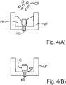
- the abutment AB is introduced together with the wax model WM in a muffle shape MF, which is then provided by means of a suitable filling material FM, to cover the area outside of the wax model WM. While embedding the wax model WM in the Filling material FM is also an Anargen to get access to the area of the wax model WM.
- Fig. 5 (B) schematically indicated by the pin ST.
- the abutment AB comprises a passage DF which completely penetrates the abutment AB in the axial direction.
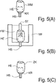
- the wax model WM begins to melt and burns out
- the porous structure of the filler supports the formation of a cavity HR within the filler FM. Consequently, within the filling material FM, the cavity HR remains as in FIG Fig. 5 (B) is shown.
- the plastic granulate can in turn be made available as a high performance polymer PEEK.
- the PEEK material is mixed with a ceramic additive, for example, to achieve a color matching of the tooth crown.
- the material is heated in the muffle in a preheating oven at 400 ° C, followed by a hot pressing of the granules, wherein the compression in the range around 380 ° C is performed.
- the actual pressing takes place in a vacuum, so that the later tooth crown can be formed without bubbles.
- a dental crown ZK As in Fig. 5 (C) is shown.
- the tooth crown ZK sits on the holding element HE, wherein the retaining pin HS can be used as anchoring point in an implant.
- an abutment AB is selected as the starting point, which corresponds to the in Fig. 1 (A) shown corresponds.
- the abutment AB consequently has no holding element HE.
- the hot pressing with the thermoplastic polymer consequently produces a structure similar to that in US Pat Fig. 5 (C) wherein the enclosing of the retaining pin HS with the thermoplastic polymer is performed in a single step without the prior formation of a retaining element HE.
- the holding element HE attached as Abutmentanteil of PEEK.
- the implant IM Underneath is the implant IM.
- the holding element HE covers in particular the grooves RI above the implant IM, which serve as retentive areas, so that after hot pressing the plastic material of the thermoplastic polymer can withdraw into these areas on cooling.
- the implant IM is made of a non-noble metal, in particular titanium, of a ceramic, in particular aluminum oxide, or of zirconium dioxide.
- this is the holding element HE made of PEEK editable and thus customizable, so that after insertion into a jawbone in Fig. 6 implant shown IM can be used as a structural element for attachment of crowns or dental bridges in dentistry.
- the illustrated embodiment may be referred to as a one-piece, two-phase implant.
- FIG. 7 Another embodiment is in Fig. 7 shown.
- a tooth crown ZK is sprayed directly onto an implant. This procedure directly creates a dental prosthetic element that can be inserted into a jawbone.
- the anchoring element is either as abutment AB according to Fig. 3 or as an implant according to Fig. 6 provided. This is followed by over-pressing or over-spraying of the dental prosthetic components with the thermoplastic polymer.
- the anchoring element according to the invention or the method according to the invention have advantages with respect to the gold and ceramic constructions known in the prior art.
- the cured PEEK proves to be easy to process and has no interaction with other materials. Due to the high load capacity and breaking strength combined with low weight, a very robust dental prosthesis is created. This can be used accurately, reproducibly and free of stress cracks. By additives, such.
- ceramic materials which consists of a high-performance polymer tooth crown ZK is color comparable to the other teeth or crowns and there is no gum irritation on.
- the PEEK high-performance polymer used can take up chewing forces of up to 1,000 MPa, thus ensuring high resistance to breakage at the same time high safety reserves are achieved.
- This material is also biocompatible, as has already been shown in human medicine, for example, in artificial hip replacements, finger joints or heart valves.
- abutment AB according to the invention or the method according to the invention can be used in many dental prosthetic applications. These may include, for example, crown bridges or similar web constructions.
Landscapes
- Health & Medical Sciences (AREA)
- General Health & Medical Sciences (AREA)
- Oral & Maxillofacial Surgery (AREA)
- Veterinary Medicine (AREA)
- Public Health (AREA)
- Epidemiology (AREA)
- Life Sciences & Earth Sciences (AREA)
- Animal Behavior & Ethology (AREA)
- Dentistry (AREA)
- Orthopedic Medicine & Surgery (AREA)
- Engineering & Computer Science (AREA)
- Chemical & Material Sciences (AREA)
- Composite Materials (AREA)
- Mechanical Engineering (AREA)
- Plastic & Reconstructive Surgery (AREA)
- Ceramic Engineering (AREA)
- Manufacturing & Machinery (AREA)
- Dental Prosthetics (AREA)
- Dental Preparations (AREA)
Claims (12)
- Procédé de surpression d'un pilier ou d'une partie de pilier d'un implant avec un système de prothèse dentaire, selon lequel les étapes suivantes sont réalisées :- la préparation d'un pilier (AB) ou d'un implant (IM) comprenant un élément support (HE) ;- la préparation d'un modèle en cire (WM) de telle sorte que le pilier (AB) ou l'implant (IM) soit muni du modèle en cire dans la zone de l'élément support (HE) ;- l'introduction du pilier (AB) ou de l'implant (IM) dans un moule à moufle (MF) ;- l'inclusion du modèle en cire (WM) dans le moule à moufle (MF) ;- le lavage du moule à moufle (MF) ;- le remplissage du moule à moufle (MF) avec un granulat d'un polymère thermoplastique ; et- la compression à chaud du granulat afin d'obtenir le dispositif de prothèse dentaire (ZK) comprenant le pilier (AB) ou l'implant (IM).
- Procédé selon la revendication 1, selon lequel la PEEK est utilisée en tant que polymère thermoplastique.
- Procédé selon la revendication 1 ou 2, selon lequel le polymère thermoplastique est mélangé avec un additif céramique.
- Procédé selon l'une quelconque des revendications 1 à 3, selon lequel le pilier (AB) ou la partie de pilier de l'implant (IM) est préparé sous la forme d'un élément d'ancrage, qui peut être ancré dans une première partie (TB1) dans un os maxillaire ou un implant, et qui est approprié pour recevoir ou former dans une seconde partie (TB2) un élément (ZK) de prothèse dentaire, l'élément d'ancrage présentant entre la première partie (TB1) et la seconde partie (TB2) un collet (KR) en saillie en direction radiale qui entoure au moins partiellement la circonférence de l'élément d'ancrage, la partie se trouvant au-dessus du collet (KR) de l'élément d'ancrage étant recouverte au moins en partie sur toute sa surface d'un matériau plastique thermoplastique.
- Procédé selon l'une quelconque des revendications 1 à 4, selon lequel le pilier (AB) ou l'implant (IM) est fabriqué en un métal non noble, de préférence en titane ou en un alliage de titane, en une céramique, notamment en oxyde d'aluminium, ou en dioxyde de zirconium, ou en un matériau approprié pour les applications dentaires.
- Procédé selon l'une quelconque des revendications 1 à 5, selon lequel l'étape d'injection du granulat plastique (GR) pour la compression de la partie de pilier sur l'implant (IM) ou le pilier (AB) est réalisée avec chauffage dans une plage de température comprise entre 240 °C et 450 °C, de préférence dans la plage comprise entre 380 °C et 400 °C.
- Procédé selon l'une quelconque des revendications 1 à 6, selon lequel une étape de préchauffage, de préférence entre 600 °C et 650 °C, est réalisée avant l'étape de remplissage du moule à moufle (MF) avec le granulat plastique (GR).
- Procédé selon l'une quelconque des revendications 1 à 7, selon lequel l'étape d'injection est réalisée sous vide.
- Procédé selon les revendications 1 à 8, selon lequel l'élément d'ancrage comprend une goupille support (HS) pouvant être insérée dans un implant, qui comprend de préférence une section transversale non symétrique par rotation, ou un implant (IM) pouvant être ancré dans un os maxillaire.
- Procédé selon la revendication 9, selon lequel l'élément d'ancrage comprend une surface rugosifiée dans la seconde partie (TB2).
- Procédé selon l'une quelconque des revendications 9 ou 10, selon lequel l'élément d'ancrage comprend sur son côté extérieur dans la seconde zone (TB2) une surface profilée en tant que zone de rétention.
- Procédé selon la revendication 11, selon lequel la surface profilée comprend plusieurs rainures (RI) agencées en parallèle dans la direction axiale, de préférence ayant une section transversale triangulaire.
Applications Claiming Priority (2)
| Application Number | Priority Date | Filing Date | Title |
|---|---|---|---|
| DE102013100529.2A DE102013100529A1 (de) | 2013-01-18 | 2013-01-18 | Verankerungselement und Verfahren zur Herstellung |
| PCT/EP2014/050681 WO2014111413A1 (fr) | 2013-01-18 | 2014-01-15 | Élément d'ancrage et procédé de fabrication dudit élément |
Publications (2)
| Publication Number | Publication Date |
|---|---|
| EP2945563A1 EP2945563A1 (fr) | 2015-11-25 |
| EP2945563B1 true EP2945563B1 (fr) | 2018-10-17 |
Family
ID=49998251
Family Applications (1)
| Application Number | Title | Priority Date | Filing Date |
|---|---|---|---|
| EP14700853.6A Active EP2945563B1 (fr) | 2013-01-18 | 2014-01-15 | Procédé de fabrication d'un élément d'ancrage |
Country Status (8)
| Country | Link |
|---|---|
| US (2) | US20150351875A1 (fr) |
| EP (1) | EP2945563B1 (fr) |
| JP (1) | JP2016507291A (fr) |
| KR (1) | KR102260327B1 (fr) |
| CN (1) | CN104968296B (fr) |
| DE (1) | DE102013100529A1 (fr) |
| IL (1) | IL239949B (fr) |
| WO (1) | WO2014111413A1 (fr) |
Families Citing this family (15)
| Publication number | Priority date | Publication date | Assignee | Title |
|---|---|---|---|---|
| WO2015189647A1 (fr) | 2014-06-13 | 2015-12-17 | Vergoullis Loannis | Moules pour piliers implantaires et tiges d'empreinte dentaires sur mesure |
| US10639132B2 (en) * | 2014-09-12 | 2020-05-05 | Italo Lozada | Dental prosthesis |
| WO2016132345A1 (fr) * | 2015-02-20 | 2016-08-25 | Mishel Weshler | Procédé, système, col implantaire et appareil pour traitement dentaire et sur implants |
| ES2723399T3 (es) * | 2015-09-28 | 2019-08-27 | Coltene/Whaledent Ag | Procedimiento para producir bloques odontológicos de material compuesto |
| CN109789002B (zh) * | 2016-09-27 | 2021-09-28 | 瓦罗克股份有限公司 | 用于将牙齿修复体连接到牙齿种植体的系统 |
| KR101869348B1 (ko) * | 2017-07-04 | 2018-06-20 | (주) 코웰메디 | 임플란트 고정체의 제조방법 및 그에 의한 임플란트 고정체 |
| GR20170100383A (el) | 2017-08-21 | 2019-04-22 | Vp Innovato Holdings Ltd | Πυρηνας οδοντικου κολοβωματος και μεθοδος για την κατασκευη ενος οδοντικου κολοβωματος |
| KR101831612B1 (ko) * | 2017-11-07 | 2018-02-26 | 백승관 | 일체형 타입의 치과용 임플란트 |
| DE102017129176A1 (de) * | 2017-12-07 | 2019-06-13 | Bredent Gmbh & Co. Kg | Zahnprothetische Anordnung und Verfahren zur Herstellung einer zahnprothetischen Anordnung |
| KR101898413B1 (ko) * | 2018-04-16 | 2018-09-12 | 고경훈 | 팩톤을 이용한 임플란트용 어버트먼트 및 그 제조방법 |
| KR102227070B1 (ko) * | 2018-08-24 | 2021-03-17 | 주식회사 올뎃덴탈 | 치과용 폴리머 어버트먼트의 제조방법 |
| EP3659574A1 (fr) * | 2018-11-29 | 2020-06-03 | Ivoclar Vivadent AG | Procédé de production d'un lingot d'oxyde de zirconium |
| EP3725262B1 (fr) * | 2019-04-18 | 2022-11-02 | Ivoclar Vivadent AG | Procédé de démouflage dentaire ainsi que moule |
| KR102146627B1 (ko) * | 2019-05-26 | 2020-08-20 | 권혁하 | Pfm 크라운 임플란트 제조 방법 |
| TWI746408B (zh) * | 2021-05-20 | 2021-11-11 | 浩鋒 關 | 可增進穩固性的牙植體 |
Citations (4)
| Publication number | Priority date | Publication date | Assignee | Title |
|---|---|---|---|---|
| US20070031793A1 (en) * | 2005-08-03 | 2007-02-08 | Kelley Casement | Provisional crown for dental implants |
| EP2143398A1 (fr) * | 2008-07-12 | 2010-01-13 | Gerd Axel Dr. Walther | Implant dentaire avec element intermédiaire élastique |
| WO2011034780A1 (fr) * | 2009-09-15 | 2011-03-24 | 3M Innovative Properties Company | Points d'appui d'implant dentaire et procédés d'utilisation |
| WO2011056450A2 (fr) * | 2009-10-28 | 2011-05-12 | 3M Innovative Properties Company | Articles de type implants dentaires et procédés associés |
Family Cites Families (27)
| Publication number | Priority date | Publication date | Assignee | Title |
|---|---|---|---|---|
| US3905106A (en) * | 1970-09-08 | 1975-09-16 | Policlinica De Stomatologie Pr | Method for fabricating dental bridges dental crowns and corono-radicular retainers |
| SE414399B (sv) * | 1976-03-16 | 1980-07-28 | Hans Scheicher | Keramiskt material for anvendning inom medicinen, i synnerhet for framstellning av implantat, fremst odontologiska implantat samt sett for framstellning av materialet |
| WO1992014422A1 (fr) * | 1991-02-20 | 1992-09-03 | Tdk Corporation | Bio-implant composite et methode de production |
| AU683050B2 (en) * | 1993-06-24 | 1997-10-30 | Dentsply Gmbh | Dental prosthesis |
| US6485849B2 (en) * | 1994-05-31 | 2002-11-26 | Tec Ventures, Inc. | Method for molding dental restorations and related apparatus |
| EP0886496A1 (fr) * | 1996-02-29 | 1998-12-30 | Implant Innovations, Inc. | Systeme de reconstitution dentaire pour une seule dent |
| FI972890A (fi) * | 1997-07-08 | 1999-01-09 | Bioxid Oy | Uusi muovipohjainen komposiitti ja sen käytt¦ |
| US6116070A (en) * | 1998-11-11 | 2000-09-12 | Advanced Research And Technology Institute | Superplastically-formed prosthetic components, and equipment for same |
| US6669476B2 (en) * | 2000-06-27 | 2003-12-30 | David Michael Prestipino | Nanophase dental prosthetics and method |
| US20060046229A1 (en) * | 2004-08-26 | 2006-03-02 | Teich Thomas J | Dental implant |
| GB2424223C (en) * | 2005-03-07 | 2011-02-02 | Massachusetts Inst Technology | Biomaterial. |
| DE102005016939A1 (de) * | 2005-04-12 | 2006-10-19 | Vekörrer, Franz | Verfahren zur Herstellung von Dentalformteilen |
| AU2006249942B2 (en) * | 2005-05-26 | 2011-07-07 | Zimmer Dental, Inc. | Prosthetic dental device |
| DE102006033794B3 (de) * | 2006-07-19 | 2008-03-06 | BEGO Bremer Goldschlägerei Wilh. Herbst GmbH & Co. KG | Elementesatz zur Herstellung einer dentalen Prothese, System zur Herstellung einer dentalen Prothese oder eines Elementesatzes sowie entsprechende Herstellverfahren |
| JP5378218B2 (ja) * | 2006-09-25 | 2013-12-25 | オーソビタ, インコーポレイテッド | 生理活性負荷支持複合体 |
| EP2486948B1 (fr) * | 2007-04-10 | 2018-02-21 | Zimmer, Inc. | Polyéthylène antioxydant, réticulé, stabilisé, à poids moléculaire très élevé pour des applications de dispositifs médicaux |
| CN201112665Y (zh) * | 2007-08-28 | 2008-09-10 | 富士康(昆山)电脑接插件有限公司 | 电连接器组件 |
| GB0805052D0 (en) * | 2008-03-19 | 2008-04-16 | 3M Innovative Properties Co | A method for making a dental blank, a press and a system for making dental blanks |
| US20100145393A1 (en) * | 2008-12-05 | 2010-06-10 | Medicinelodge, Inc. | Medical and dental porous implants |
| US20110287382A1 (en) * | 2009-02-12 | 2011-11-24 | Johnson Ryan E | Methods of making and using dental articles for tooth implants and preformed dental articles |
| US8609127B2 (en) * | 2009-04-03 | 2013-12-17 | Warsaw Orthopedic, Inc. | Medical implant with bioactive material and method of making the medical implant |
| BR112012016027B1 (pt) * | 2009-12-11 | 2019-01-15 | Difusion Technologies, Inc. | método de produção de implantes antimicrobianos de polieteretercetona |
| DE102011001403A1 (de) * | 2011-03-18 | 2012-09-20 | Frank-Peter Spahn | Zahnimplantat und Verfahren zur Herstellung oder zur Bearbeitung eines Zahnimplantats |
| US20130017511A1 (en) * | 2011-07-15 | 2013-01-17 | Shofu, Inc. | Implant fixture |
| EP2736446B1 (fr) * | 2011-07-27 | 2020-09-02 | Abracadabra Implants Ltd | Assemblage de restauration prosthodontique |
| WO2013059939A1 (fr) * | 2011-10-26 | 2013-05-02 | Permatooth Inc. | Système de montage d'un remplacement dentaire |
| US8708033B2 (en) * | 2012-08-29 | 2014-04-29 | General Electric Company | Calcium titanate containing mold compositions and methods for casting titanium and titanium aluminide alloys |
-
2013
- 2013-01-18 DE DE102013100529.2A patent/DE102013100529A1/de active Pending
-
2014
- 2014-01-15 EP EP14700853.6A patent/EP2945563B1/fr active Active
- 2014-01-15 US US14/761,691 patent/US20150351875A1/en not_active Abandoned
- 2014-01-15 KR KR1020157020763A patent/KR102260327B1/ko active IP Right Grant
- 2014-01-15 JP JP2015553065A patent/JP2016507291A/ja active Pending
- 2014-01-15 WO PCT/EP2014/050681 patent/WO2014111413A1/fr active Application Filing
- 2014-01-15 CN CN201480005035.2A patent/CN104968296B/zh active Active
-
2015
- 2015-07-15 IL IL239949A patent/IL239949B/en active IP Right Grant
-
2018
- 2018-12-12 US US16/217,795 patent/US20190175309A1/en not_active Abandoned
Patent Citations (4)
| Publication number | Priority date | Publication date | Assignee | Title |
|---|---|---|---|---|
| US20070031793A1 (en) * | 2005-08-03 | 2007-02-08 | Kelley Casement | Provisional crown for dental implants |
| EP2143398A1 (fr) * | 2008-07-12 | 2010-01-13 | Gerd Axel Dr. Walther | Implant dentaire avec element intermédiaire élastique |
| WO2011034780A1 (fr) * | 2009-09-15 | 2011-03-24 | 3M Innovative Properties Company | Points d'appui d'implant dentaire et procédés d'utilisation |
| WO2011056450A2 (fr) * | 2009-10-28 | 2011-05-12 | 3M Innovative Properties Company | Articles de type implants dentaires et procédés associés |
Also Published As
| Publication number | Publication date |
|---|---|
| IL239949B (en) | 2020-09-30 |
| DE102013100529A1 (de) | 2014-07-24 |
| IL239949A0 (en) | 2015-08-31 |
| WO2014111413A1 (fr) | 2014-07-24 |
| JP2016507291A (ja) | 2016-03-10 |
| EP2945563A1 (fr) | 2015-11-25 |
| KR102260327B1 (ko) | 2021-06-04 |
| US20150351875A1 (en) | 2015-12-10 |
| CN104968296B (zh) | 2019-04-09 |
| KR20150109382A (ko) | 2015-10-01 |
| US20190175309A1 (en) | 2019-06-13 |
| CN104968296A (zh) | 2015-10-07 |
Similar Documents
| Publication | Publication Date | Title |
|---|---|---|
| EP2945563B1 (fr) | Procédé de fabrication d'un élément d'ancrage | |
| DE60118563T2 (de) | Kappen mit Abstandshaltern | |
| DE102011103027A1 (de) | Verbundkrone/Verbundbrücke und Verfahren zu deren Herstellung | |
| EP3016610B1 (fr) | Demi-produit destiné à la fabrication de systèmes de prothèses dentaires, pilier et procédé de fabrication de systèmes de prothèses dentaires | |
| DE102012108153A1 (de) | Rohling und Verfahren zur Herstellung einer Dentalrestauration durch substraktive Bearbeitung | |
| EP2713937A1 (fr) | Couronne composite/bridge composite et procédé pour fabrication de ladite couronne/dudit bridge | |
| DE102008058305B4 (de) | Verfahren zur Herstellung einer Verbindungsvorrichtung zur Befestigung einer dentalen Prothese an einem Kieferknochen | |
| EP1523952A2 (fr) | Elément de restauration dentaire | |
| WO2024083626A1 (fr) | Couronne télescopique, prothèse dentaire comportant une telle couronne télescopique, et procédé de production d'un dispositif prothétique ayant une prothèse dentaire | |
| EP0957813B1 (fr) | Materiau stratifie pour pieces d'appui pour protheses dentaires, pieces d'appui et procede de fabrication de celles-ci | |
| WO2015055793A1 (fr) | Gabarit de transfert dentaire | |
| EP1982673B1 (fr) | Dispositif d'installation dans une structure de support | |
| WO2014131646A2 (fr) | Système d'implant dentaire muni d'une vis de forme ajustée | |
| DE102007025164A1 (de) | Verfahren und Vorrichtungen zum Erstellen eines Modells eines Patientengebisses | |
| EP3125819B1 (fr) | Procédé de fabrication d'une couronne dentaire prothétique, couronne dentaire et couverture dentaire utilisant cette couronne | |
| DE10313825B4 (de) | Mit einem Dentalimplantat verbindbarer Aufbau und Verfahren zur Herstellung eines solchen Aufbaus | |
| DE19929441C2 (de) | Künstliche Zahnkrone und Verfahren zu ihrer Herstellung | |
| DE102022127938A1 (de) | Verfahren zur Herstellung einer Zahnprothese | |
| DE19713289C2 (de) | Wurzelstiftsystem und Versorgen von koronaltief zerstörten Frontzähnen, Eckzähnen und Prämolaren im Ober- und im Unterkiefer | |
| WO2017097911A1 (fr) | Pivot radiculaire | |
| WO2014170111A1 (fr) | Procédé de fabrication d'un modele de dentition de precision pour la fabrication/l'adaptation d'une prothese dentaire | |
| EP0878172A1 (fr) | Dispositif de soutien préfabriqué | |
| DE10337462A1 (de) | Verbindungsvorrichtung | |
| DE102006062719B4 (de) | Abstützpfosten | |
| DE102006046273B3 (de) | Basisplatte sowie Verfahren zur Herstellung einer Zahnprothese |
Legal Events
| Date | Code | Title | Description |
|---|---|---|---|
| PUAI | Public reference made under article 153(3) epc to a published international application that has entered the european phase |
Free format text: ORIGINAL CODE: 0009012 |
|
| 17P | Request for examination filed |
Effective date: 20150818 |
|
| AK | Designated contracting states |
Kind code of ref document: A1 Designated state(s): AL AT BE BG CH CY CZ DE DK EE ES FI FR GB GR HR HU IE IS IT LI LT LU LV MC MK MT NL NO PL PT RO RS SE SI SK SM TR |
|
| AX | Request for extension of the european patent |
Extension state: BA ME |
|
| DAX | Request for extension of the european patent (deleted) | ||
| 17Q | First examination report despatched |
Effective date: 20160804 |
|
| STAA | Information on the status of an ep patent application or granted ep patent |
Free format text: STATUS: EXAMINATION IS IN PROGRESS |
|
| GRAP | Despatch of communication of intention to grant a patent |
Free format text: ORIGINAL CODE: EPIDOSNIGR1 |
|
| STAA | Information on the status of an ep patent application or granted ep patent |
Free format text: STATUS: GRANT OF PATENT IS INTENDED |
|
| INTG | Intention to grant announced |
Effective date: 20180430 |
|
| GRAJ | Information related to disapproval of communication of intention to grant by the applicant or resumption of examination proceedings by the epo deleted |
Free format text: ORIGINAL CODE: EPIDOSDIGR1 |
|
| STAA | Information on the status of an ep patent application or granted ep patent |
Free format text: STATUS: EXAMINATION IS IN PROGRESS |
|
| GRAR | Information related to intention to grant a patent recorded |
Free format text: ORIGINAL CODE: EPIDOSNIGR71 |
|
| GRAS | Grant fee paid |
Free format text: ORIGINAL CODE: EPIDOSNIGR3 |
|
| STAA | Information on the status of an ep patent application or granted ep patent |
Free format text: STATUS: GRANT OF PATENT IS INTENDED |
|
| GRAA | (expected) grant |
Free format text: ORIGINAL CODE: 0009210 |
|
| STAA | Information on the status of an ep patent application or granted ep patent |
Free format text: STATUS: THE PATENT HAS BEEN GRANTED |
|
| INTC | Intention to grant announced (deleted) | ||
| INTG | Intention to grant announced |
Effective date: 20180906 |
|
| AK | Designated contracting states |
Kind code of ref document: B1 Designated state(s): AL AT BE BG CH CY CZ DE DK EE ES FI FR GB GR HR HU IE IS IT LI LT LU LV MC MK MT NL NO PL PT RO RS SE SI SK SM TR |
|
| REG | Reference to a national code |
Ref country code: GB Ref legal event code: FG4D Free format text: NOT ENGLISH |
|
| REG | Reference to a national code |
Ref country code: CH Ref legal event code: EP |
|
| REG | Reference to a national code |
Ref country code: IE Ref legal event code: FG4D Free format text: LANGUAGE OF EP DOCUMENT: GERMAN |
|
| REG | Reference to a national code |
Ref country code: DE Ref legal event code: R096 Ref document number: 502014009787 Country of ref document: DE Ref country code: AT Ref legal event code: REF Ref document number: 1053079 Country of ref document: AT Kind code of ref document: T Effective date: 20181115 |
|
| REG | Reference to a national code |
Ref country code: SE Ref legal event code: TRGR |
|
| REG | Reference to a national code |
Ref country code: NL Ref legal event code: MP Effective date: 20181017 |
|
| REG | Reference to a national code |
Ref country code: LT Ref legal event code: MG4D |
|
| PG25 | Lapsed in a contracting state [announced via postgrant information from national office to epo] |
Ref country code: NL Free format text: LAPSE BECAUSE OF FAILURE TO SUBMIT A TRANSLATION OF THE DESCRIPTION OR TO PAY THE FEE WITHIN THE PRESCRIBED TIME-LIMIT Effective date: 20181017 |
|
| PG25 | Lapsed in a contracting state [announced via postgrant information from national office to epo] |
Ref country code: ES Free format text: LAPSE BECAUSE OF FAILURE TO SUBMIT A TRANSLATION OF THE DESCRIPTION OR TO PAY THE FEE WITHIN THE PRESCRIBED TIME-LIMIT Effective date: 20181017 Ref country code: LV Free format text: LAPSE BECAUSE OF FAILURE TO SUBMIT A TRANSLATION OF THE DESCRIPTION OR TO PAY THE FEE WITHIN THE PRESCRIBED TIME-LIMIT Effective date: 20181017 Ref country code: FI Free format text: LAPSE BECAUSE OF FAILURE TO SUBMIT A TRANSLATION OF THE DESCRIPTION OR TO PAY THE FEE WITHIN THE PRESCRIBED TIME-LIMIT Effective date: 20181017 Ref country code: IS Free format text: LAPSE BECAUSE OF FAILURE TO SUBMIT A TRANSLATION OF THE DESCRIPTION OR TO PAY THE FEE WITHIN THE PRESCRIBED TIME-LIMIT Effective date: 20190217 Ref country code: NO Free format text: LAPSE BECAUSE OF FAILURE TO SUBMIT A TRANSLATION OF THE DESCRIPTION OR TO PAY THE FEE WITHIN THE PRESCRIBED TIME-LIMIT Effective date: 20190117 Ref country code: HR Free format text: LAPSE BECAUSE OF FAILURE TO SUBMIT A TRANSLATION OF THE DESCRIPTION OR TO PAY THE FEE WITHIN THE PRESCRIBED TIME-LIMIT Effective date: 20181017 Ref country code: PL Free format text: LAPSE BECAUSE OF FAILURE TO SUBMIT A TRANSLATION OF THE DESCRIPTION OR TO PAY THE FEE WITHIN THE PRESCRIBED TIME-LIMIT Effective date: 20181017 Ref country code: LT Free format text: LAPSE BECAUSE OF FAILURE TO SUBMIT A TRANSLATION OF THE DESCRIPTION OR TO PAY THE FEE WITHIN THE PRESCRIBED TIME-LIMIT Effective date: 20181017 Ref country code: BG Free format text: LAPSE BECAUSE OF FAILURE TO SUBMIT A TRANSLATION OF THE DESCRIPTION OR TO PAY THE FEE WITHIN THE PRESCRIBED TIME-LIMIT Effective date: 20190117 |
|
| PG25 | Lapsed in a contracting state [announced via postgrant information from national office to epo] |
Ref country code: RS Free format text: LAPSE BECAUSE OF FAILURE TO SUBMIT A TRANSLATION OF THE DESCRIPTION OR TO PAY THE FEE WITHIN THE PRESCRIBED TIME-LIMIT Effective date: 20181017 Ref country code: GR Free format text: LAPSE BECAUSE OF FAILURE TO SUBMIT A TRANSLATION OF THE DESCRIPTION OR TO PAY THE FEE WITHIN THE PRESCRIBED TIME-LIMIT Effective date: 20190118 Ref country code: PT Free format text: LAPSE BECAUSE OF FAILURE TO SUBMIT A TRANSLATION OF THE DESCRIPTION OR TO PAY THE FEE WITHIN THE PRESCRIBED TIME-LIMIT Effective date: 20190217 Ref country code: AL Free format text: LAPSE BECAUSE OF FAILURE TO SUBMIT A TRANSLATION OF THE DESCRIPTION OR TO PAY THE FEE WITHIN THE PRESCRIBED TIME-LIMIT Effective date: 20181017 |
|
| REG | Reference to a national code |
Ref country code: DE Ref legal event code: R097 Ref document number: 502014009787 Country of ref document: DE |
|
| PG25 | Lapsed in a contracting state [announced via postgrant information from national office to epo] |
Ref country code: CZ Free format text: LAPSE BECAUSE OF FAILURE TO SUBMIT A TRANSLATION OF THE DESCRIPTION OR TO PAY THE FEE WITHIN THE PRESCRIBED TIME-LIMIT Effective date: 20181017 Ref country code: DK Free format text: LAPSE BECAUSE OF FAILURE TO SUBMIT A TRANSLATION OF THE DESCRIPTION OR TO PAY THE FEE WITHIN THE PRESCRIBED TIME-LIMIT Effective date: 20181017 |
|
| PLBE | No opposition filed within time limit |
Free format text: ORIGINAL CODE: 0009261 |
|
| STAA | Information on the status of an ep patent application or granted ep patent |
Free format text: STATUS: NO OPPOSITION FILED WITHIN TIME LIMIT |
|
| PG25 | Lapsed in a contracting state [announced via postgrant information from national office to epo] |
Ref country code: RO Free format text: LAPSE BECAUSE OF FAILURE TO SUBMIT A TRANSLATION OF THE DESCRIPTION OR TO PAY THE FEE WITHIN THE PRESCRIBED TIME-LIMIT Effective date: 20181017 Ref country code: SK Free format text: LAPSE BECAUSE OF FAILURE TO SUBMIT A TRANSLATION OF THE DESCRIPTION OR TO PAY THE FEE WITHIN THE PRESCRIBED TIME-LIMIT Effective date: 20181017 Ref country code: SM Free format text: LAPSE BECAUSE OF FAILURE TO SUBMIT A TRANSLATION OF THE DESCRIPTION OR TO PAY THE FEE WITHIN THE PRESCRIBED TIME-LIMIT Effective date: 20181017 Ref country code: EE Free format text: LAPSE BECAUSE OF FAILURE TO SUBMIT A TRANSLATION OF THE DESCRIPTION OR TO PAY THE FEE WITHIN THE PRESCRIBED TIME-LIMIT Effective date: 20181017 Ref country code: MC Free format text: LAPSE BECAUSE OF FAILURE TO SUBMIT A TRANSLATION OF THE DESCRIPTION OR TO PAY THE FEE WITHIN THE PRESCRIBED TIME-LIMIT Effective date: 20181017 |
|
| 26N | No opposition filed |
Effective date: 20190718 |
|
| GBPC | Gb: european patent ceased through non-payment of renewal fee |
Effective date: 20190117 |
|
| PG25 | Lapsed in a contracting state [announced via postgrant information from national office to epo] |
Ref country code: LU Free format text: LAPSE BECAUSE OF NON-PAYMENT OF DUE FEES Effective date: 20190115 |
|
| REG | Reference to a national code |
Ref country code: BE Ref legal event code: MM Effective date: 20190131 |
|
| REG | Reference to a national code |
Ref country code: IE Ref legal event code: MM4A |
|
| PG25 | Lapsed in a contracting state [announced via postgrant information from national office to epo] |
Ref country code: SI Free format text: LAPSE BECAUSE OF FAILURE TO SUBMIT A TRANSLATION OF THE DESCRIPTION OR TO PAY THE FEE WITHIN THE PRESCRIBED TIME-LIMIT Effective date: 20181017 |
|
| PG25 | Lapsed in a contracting state [announced via postgrant information from national office to epo] |
Ref country code: BE Free format text: LAPSE BECAUSE OF NON-PAYMENT OF DUE FEES Effective date: 20190131 |
|
| PG25 | Lapsed in a contracting state [announced via postgrant information from national office to epo] |
Ref country code: GB Free format text: LAPSE BECAUSE OF NON-PAYMENT OF DUE FEES Effective date: 20190117 |
|
| PG25 | Lapsed in a contracting state [announced via postgrant information from national office to epo] |
Ref country code: IE Free format text: LAPSE BECAUSE OF NON-PAYMENT OF DUE FEES Effective date: 20190115 |
|
| REG | Reference to a national code |
Ref country code: AT Ref legal event code: MM01 Ref document number: 1053079 Country of ref document: AT Kind code of ref document: T Effective date: 20190115 |
|
| PG25 | Lapsed in a contracting state [announced via postgrant information from national office to epo] |
Ref country code: TR Free format text: LAPSE BECAUSE OF FAILURE TO SUBMIT A TRANSLATION OF THE DESCRIPTION OR TO PAY THE FEE WITHIN THE PRESCRIBED TIME-LIMIT Effective date: 20181017 |
|
| PG25 | Lapsed in a contracting state [announced via postgrant information from national office to epo] |
Ref country code: AT Free format text: LAPSE BECAUSE OF NON-PAYMENT OF DUE FEES Effective date: 20190115 |
|
| PG25 | Lapsed in a contracting state [announced via postgrant information from national office to epo] |
Ref country code: MT Free format text: LAPSE BECAUSE OF FAILURE TO SUBMIT A TRANSLATION OF THE DESCRIPTION OR TO PAY THE FEE WITHIN THE PRESCRIBED TIME-LIMIT Effective date: 20181017 |
|
| PG25 | Lapsed in a contracting state [announced via postgrant information from national office to epo] |
Ref country code: CY Free format text: LAPSE BECAUSE OF FAILURE TO SUBMIT A TRANSLATION OF THE DESCRIPTION OR TO PAY THE FEE WITHIN THE PRESCRIBED TIME-LIMIT Effective date: 20181017 |
|
| PG25 | Lapsed in a contracting state [announced via postgrant information from national office to epo] |
Ref country code: HU Free format text: LAPSE BECAUSE OF FAILURE TO SUBMIT A TRANSLATION OF THE DESCRIPTION OR TO PAY THE FEE WITHIN THE PRESCRIBED TIME-LIMIT; INVALID AB INITIO Effective date: 20140115 |
|
| PG25 | Lapsed in a contracting state [announced via postgrant information from national office to epo] |
Ref country code: MK Free format text: LAPSE BECAUSE OF FAILURE TO SUBMIT A TRANSLATION OF THE DESCRIPTION OR TO PAY THE FEE WITHIN THE PRESCRIBED TIME-LIMIT Effective date: 20181017 |
|
| PGFP | Annual fee paid to national office [announced via postgrant information from national office to epo] |
Ref country code: FR Payment date: 20230123 Year of fee payment: 10 |
|
| PGFP | Annual fee paid to national office [announced via postgrant information from national office to epo] |
Ref country code: SE Payment date: 20230123 Year of fee payment: 10 Ref country code: IT Payment date: 20230131 Year of fee payment: 10 |
|
| PGFP | Annual fee paid to national office [announced via postgrant information from national office to epo] |
Ref country code: DE Payment date: 20240131 Year of fee payment: 11 Ref country code: CH Payment date: 20240202 Year of fee payment: 11 |