EP2945563B1 - Verfahren zur herstellung eines verankerungselements - Google Patents
Verfahren zur herstellung eines verankerungselements Download PDFInfo
- Publication number
- EP2945563B1 EP2945563B1 EP14700853.6A EP14700853A EP2945563B1 EP 2945563 B1 EP2945563 B1 EP 2945563B1 EP 14700853 A EP14700853 A EP 14700853A EP 2945563 B1 EP2945563 B1 EP 2945563B1
- Authority
- EP
- European Patent Office
- Prior art keywords
- implant
- abutment
- anchoring element
- subregion
- muffle
- Prior art date
- Legal status (The legal status is an assumption and is not a legal conclusion. Google has not performed a legal analysis and makes no representation as to the accuracy of the status listed.)
- Active
Links
- 238000004873 anchoring Methods 0.000 title claims description 37
- 238000004519 manufacturing process Methods 0.000 title description 6
- 239000007943 implant Substances 0.000 claims description 82
- 238000000034 method Methods 0.000 claims description 46
- 239000000463 material Substances 0.000 claims description 21
- 239000004696 Poly ether ether ketone Substances 0.000 claims description 19
- 229920002530 polyetherether ketone Polymers 0.000 claims description 19
- JUPQTSLXMOCDHR-UHFFFAOYSA-N benzene-1,4-diol;bis(4-fluorophenyl)methanone Chemical compound OC1=CC=C(O)C=C1.C1=CC(F)=CC=C1C(=O)C1=CC=C(F)C=C1 JUPQTSLXMOCDHR-UHFFFAOYSA-N 0.000 claims description 18
- 229920001169 thermoplastic Polymers 0.000 claims description 18
- 238000003825 pressing Methods 0.000 claims description 14
- 239000008187 granular material Substances 0.000 claims description 13
- RTAQQCXQSZGOHL-UHFFFAOYSA-N Titanium Chemical compound [Ti] RTAQQCXQSZGOHL-UHFFFAOYSA-N 0.000 claims description 11
- 239000000919 ceramic Substances 0.000 claims description 11
- 238000007731 hot pressing Methods 0.000 claims description 11
- 239000010936 titanium Substances 0.000 claims description 11
- 229910052719 titanium Inorganic materials 0.000 claims description 10
- MCMNRKCIXSYSNV-UHFFFAOYSA-N ZrO2 Inorganic materials O=[Zr]=O MCMNRKCIXSYSNV-UHFFFAOYSA-N 0.000 claims description 9
- RVTZCBVAJQQJTK-UHFFFAOYSA-N oxygen(2-);zirconium(4+) Chemical compound [O-2].[O-2].[Zr+4] RVTZCBVAJQQJTK-UHFFFAOYSA-N 0.000 claims description 7
- 238000010438 heat treatment Methods 0.000 claims description 6
- PNEYBMLMFCGWSK-UHFFFAOYSA-N Alumina Chemical compound [O-2].[O-2].[O-2].[Al+3].[Al+3] PNEYBMLMFCGWSK-UHFFFAOYSA-N 0.000 claims description 4
- 229920000426 Microplastic Polymers 0.000 claims description 4
- 239000000654 additive Substances 0.000 claims description 4
- 230000000996 additive effect Effects 0.000 claims description 3
- 239000012815 thermoplastic material Substances 0.000 claims description 3
- 229910001069 Ti alloy Inorganic materials 0.000 claims 1
- 239000010953 base metal Substances 0.000 claims 1
- 239000004033 plastic Substances 0.000 description 13
- 229920003023 plastic Polymers 0.000 description 13
- 229920000642 polymer Polymers 0.000 description 11
- 210000000332 tooth crown Anatomy 0.000 description 9
- 239000004053 dental implant Substances 0.000 description 5
- 229910000510 noble metal Inorganic materials 0.000 description 5
- 238000001816 cooling Methods 0.000 description 4
- 238000003780 insertion Methods 0.000 description 4
- 230000037431 insertion Effects 0.000 description 4
- TWNQGVIAIRXVLR-UHFFFAOYSA-N oxo(oxoalumanyloxy)alumane Chemical compound O=[Al]O[Al]=O TWNQGVIAIRXVLR-UHFFFAOYSA-N 0.000 description 4
- 229910010293 ceramic material Inorganic materials 0.000 description 3
- 230000001055 chewing effect Effects 0.000 description 3
- 150000001875 compounds Chemical class 0.000 description 3
- 238000004026 adhesive bonding Methods 0.000 description 2
- 230000015572 biosynthetic process Effects 0.000 description 2
- 238000007906 compression Methods 0.000 description 2
- 238000010276 construction Methods 0.000 description 2
- 239000005548 dental material Substances 0.000 description 2
- 239000003814 drug Substances 0.000 description 2
- 239000000945 filler Substances 0.000 description 2
- 230000007794 irritation Effects 0.000 description 2
- 239000004416 thermosoftening plastic Substances 0.000 description 2
- 229910000831 Steel Inorganic materials 0.000 description 1
- 239000000853 adhesive Substances 0.000 description 1
- 230000001070 adhesive effect Effects 0.000 description 1
- 239000000560 biocompatible material Substances 0.000 description 1
- 230000015556 catabolic process Effects 0.000 description 1
- 230000002925 chemical effect Effects 0.000 description 1
- 230000006835 compression Effects 0.000 description 1
- 238000006731 degradation reaction Methods 0.000 description 1
- 230000001419 dependent effect Effects 0.000 description 1
- WVMPCBWWBLZKPD-UHFFFAOYSA-N dilithium oxido-[oxido(oxo)silyl]oxy-oxosilane Chemical compound [Li+].[Li+].[O-][Si](=O)O[Si]([O-])=O WVMPCBWWBLZKPD-UHFFFAOYSA-N 0.000 description 1
- 238000002474 experimental method Methods 0.000 description 1
- 210000001145 finger joint Anatomy 0.000 description 1
- PCHJSUWPFVWCPO-UHFFFAOYSA-N gold Chemical compound [Au] PCHJSUWPFVWCPO-UHFFFAOYSA-N 0.000 description 1
- 239000010931 gold Substances 0.000 description 1
- 229910052737 gold Inorganic materials 0.000 description 1
- 210000003709 heart valve Anatomy 0.000 description 1
- 229920006258 high performance thermoplastic Polymers 0.000 description 1
- 238000011540 hip replacement Methods 0.000 description 1
- 238000002347 injection Methods 0.000 description 1
- 239000007924 injection Substances 0.000 description 1
- 230000003993 interaction Effects 0.000 description 1
- 238000002844 melting Methods 0.000 description 1
- 230000008018 melting Effects 0.000 description 1
- 229910044991 metal oxide Inorganic materials 0.000 description 1
- 150000004706 metal oxides Chemical class 0.000 description 1
- 238000000465 moulding Methods 0.000 description 1
- 230000000704 physical effect Effects 0.000 description 1
- 239000010970 precious metal Substances 0.000 description 1
- 230000002787 reinforcement Effects 0.000 description 1
- 230000003763 resistance to breakage Effects 0.000 description 1
- 238000007493 shaping process Methods 0.000 description 1
- 238000005507 spraying Methods 0.000 description 1
- 239000010959 steel Substances 0.000 description 1
- GWEVSGVZZGPLCZ-UHFFFAOYSA-N titanium dioxide Inorganic materials O=[Ti]=O GWEVSGVZZGPLCZ-UHFFFAOYSA-N 0.000 description 1
Images


Classifications
-
- A—HUMAN NECESSITIES
- A61—MEDICAL OR VETERINARY SCIENCE; HYGIENE
- A61C—DENTISTRY; APPARATUS OR METHODS FOR ORAL OR DENTAL HYGIENE
- A61C13/00—Dental prostheses; Making same
-
- A—HUMAN NECESSITIES
- A61—MEDICAL OR VETERINARY SCIENCE; HYGIENE
- A61C—DENTISTRY; APPARATUS OR METHODS FOR ORAL OR DENTAL HYGIENE
- A61C13/00—Dental prostheses; Making same
- A61C13/0003—Making bridge-work, inlays, implants or the like
- A61C13/0006—Production methods
-
- A—HUMAN NECESSITIES
- A61—MEDICAL OR VETERINARY SCIENCE; HYGIENE
- A61C—DENTISTRY; APPARATUS OR METHODS FOR ORAL OR DENTAL HYGIENE
- A61C8/00—Means to be fixed to the jaw-bone for consolidating natural teeth or for fixing dental prostheses thereon; Dental implants; Implanting tools
- A61C8/0012—Means to be fixed to the jaw-bone for consolidating natural teeth or for fixing dental prostheses thereon; Dental implants; Implanting tools characterised by the material or composition, e.g. ceramics, surface layer, metal alloy
- A61C8/0016—Means to be fixed to the jaw-bone for consolidating natural teeth or for fixing dental prostheses thereon; Dental implants; Implanting tools characterised by the material or composition, e.g. ceramics, surface layer, metal alloy polymeric material
-
- A—HUMAN NECESSITIES
- A61—MEDICAL OR VETERINARY SCIENCE; HYGIENE
- A61C—DENTISTRY; APPARATUS OR METHODS FOR ORAL OR DENTAL HYGIENE
- A61C8/00—Means to be fixed to the jaw-bone for consolidating natural teeth or for fixing dental prostheses thereon; Dental implants; Implanting tools
- A61C8/0018—Means to be fixed to the jaw-bone for consolidating natural teeth or for fixing dental prostheses thereon; Dental implants; Implanting tools characterised by the shape
- A61C8/0022—Self-screwing
- A61C8/0025—Self-screwing with multiple threads
-
- A—HUMAN NECESSITIES
- A61—MEDICAL OR VETERINARY SCIENCE; HYGIENE
- A61C—DENTISTRY; APPARATUS OR METHODS FOR ORAL OR DENTAL HYGIENE
- A61C8/00—Means to be fixed to the jaw-bone for consolidating natural teeth or for fixing dental prostheses thereon; Dental implants; Implanting tools
- A61C8/0048—Connecting the upper structure to the implant, e.g. bridging bars
- A61C8/005—Connecting devices for joining an upper structure with an implant member, e.g. spacers
- A61C8/0051—Abutment monobloc with restoration
-
- B—PERFORMING OPERATIONS; TRANSPORTING
- B29—WORKING OF PLASTICS; WORKING OF SUBSTANCES IN A PLASTIC STATE IN GENERAL
- B29C—SHAPING OR JOINING OF PLASTICS; SHAPING OF MATERIAL IN A PLASTIC STATE, NOT OTHERWISE PROVIDED FOR; AFTER-TREATMENT OF THE SHAPED PRODUCTS, e.g. REPAIRING
- B29C70/00—Shaping composites, i.e. plastics material comprising reinforcements, fillers or preformed parts, e.g. inserts
- B29C70/68—Shaping composites, i.e. plastics material comprising reinforcements, fillers or preformed parts, e.g. inserts by incorporating or moulding on preformed parts, e.g. inserts or layers, e.g. foam blocks
- B29C70/681—Component parts, details or accessories; Auxiliary operations
- B29C70/682—Preformed parts characterised by their structure, e.g. form
-
- B—PERFORMING OPERATIONS; TRANSPORTING
- B29—WORKING OF PLASTICS; WORKING OF SUBSTANCES IN A PLASTIC STATE IN GENERAL
- B29C—SHAPING OR JOINING OF PLASTICS; SHAPING OF MATERIAL IN A PLASTIC STATE, NOT OTHERWISE PROVIDED FOR; AFTER-TREATMENT OF THE SHAPED PRODUCTS, e.g. REPAIRING
- B29C70/00—Shaping composites, i.e. plastics material comprising reinforcements, fillers or preformed parts, e.g. inserts
- B29C70/68—Shaping composites, i.e. plastics material comprising reinforcements, fillers or preformed parts, e.g. inserts by incorporating or moulding on preformed parts, e.g. inserts or layers, e.g. foam blocks
- B29C70/72—Encapsulating inserts having non-encapsulated projections, e.g. extremities or terminal portions of electrical components
-
- B—PERFORMING OPERATIONS; TRANSPORTING
- B29—WORKING OF PLASTICS; WORKING OF SUBSTANCES IN A PLASTIC STATE IN GENERAL
- B29K—INDEXING SCHEME ASSOCIATED WITH SUBCLASSES B29B, B29C OR B29D, RELATING TO MOULDING MATERIALS OR TO MATERIALS FOR MOULDS, REINFORCEMENTS, FILLERS OR PREFORMED PARTS, e.g. INSERTS
- B29K2071/00—Use of polyethers, e.g. PEEK, i.e. polyether-etherketone or PEK, i.e. polyetherketone or derivatives thereof, as moulding material
-
- B—PERFORMING OPERATIONS; TRANSPORTING
- B29—WORKING OF PLASTICS; WORKING OF SUBSTANCES IN A PLASTIC STATE IN GENERAL
- B29K—INDEXING SCHEME ASSOCIATED WITH SUBCLASSES B29B, B29C OR B29D, RELATING TO MOULDING MATERIALS OR TO MATERIALS FOR MOULDS, REINFORCEMENTS, FILLERS OR PREFORMED PARTS, e.g. INSERTS
- B29K2105/00—Condition, form or state of moulded material or of the material to be shaped
- B29K2105/25—Solid
- B29K2105/251—Particles, powder or granules
-
- B—PERFORMING OPERATIONS; TRANSPORTING
- B29—WORKING OF PLASTICS; WORKING OF SUBSTANCES IN A PLASTIC STATE IN GENERAL
- B29K—INDEXING SCHEME ASSOCIATED WITH SUBCLASSES B29B, B29C OR B29D, RELATING TO MOULDING MATERIALS OR TO MATERIALS FOR MOULDS, REINFORCEMENTS, FILLERS OR PREFORMED PARTS, e.g. INSERTS
- B29K2509/00—Use of inorganic materials not provided for in groups B29K2503/00 - B29K2507/00, as filler
- B29K2509/02—Ceramics
-
- B—PERFORMING OPERATIONS; TRANSPORTING
- B29—WORKING OF PLASTICS; WORKING OF SUBSTANCES IN A PLASTIC STATE IN GENERAL
- B29K—INDEXING SCHEME ASSOCIATED WITH SUBCLASSES B29B, B29C OR B29D, RELATING TO MOULDING MATERIALS OR TO MATERIALS FOR MOULDS, REINFORCEMENTS, FILLERS OR PREFORMED PARTS, e.g. INSERTS
- B29K2705/00—Use of metals, their alloys or their compounds, for preformed parts, e.g. for inserts
- B29K2705/08—Transition metals
-
- B—PERFORMING OPERATIONS; TRANSPORTING
- B29—WORKING OF PLASTICS; WORKING OF SUBSTANCES IN A PLASTIC STATE IN GENERAL
- B29K—INDEXING SCHEME ASSOCIATED WITH SUBCLASSES B29B, B29C OR B29D, RELATING TO MOULDING MATERIALS OR TO MATERIALS FOR MOULDS, REINFORCEMENTS, FILLERS OR PREFORMED PARTS, e.g. INSERTS
- B29K2709/00—Use of inorganic materials not provided for in groups B29K2703/00 - B29K2707/00, for preformed parts, e.g. for inserts
- B29K2709/02—Ceramics
-
- B—PERFORMING OPERATIONS; TRANSPORTING
- B29—WORKING OF PLASTICS; WORKING OF SUBSTANCES IN A PLASTIC STATE IN GENERAL
- B29L—INDEXING SCHEME ASSOCIATED WITH SUBCLASS B29C, RELATING TO PARTICULAR ARTICLES
- B29L2031/00—Other particular articles
- B29L2031/753—Medical equipment; Accessories therefor
- B29L2031/7532—Artificial members, protheses
- B29L2031/7536—Artificial teeth
Definitions
- the invention relates to a method for overpressing an abutment or an abutment portion of an implant with a dental prosthetic arrangement.
- Abutments are well known in the art and are used in a variety of dental prosthetics.
- An abutment is a structural element used to fix crowns or dental bridges in dentistry.
- abutments are used as a primary or secondary support of ridge-like or telescopic dental prosthetic arrangements.
- An abutment usually has a metallic pin which is provided, for example, in combination with an implant as anchoring point in a jawbone. For example, a crown is attached to the side opposite the anchoring point.
- Known abutments are usually made of titanium.
- Implants are also known from the general state of the art. These have a screw connection on a side facing the jawbone, so that the implant can be anchored in the jaw. On the opposite side, for example, a tooth crown or the like is applied.
- a prefabricated dental implant comprising a prefabricated abutment having a subgingival end anchored in the implant and an opposite end, the opposite end permanently connected to a fusible dental material and the abutment made of a different material than the fusible dental material ,
- a dental implant consisting of a ceramic material is described with an implant body for anchoring in a jawbone and implantable into a holding receptacle of the implant body and fixable implant post, which protruding from the implant body support portion for fixing a dental prosthesis is formed and its fixable in the holding receptacle holding section and this Holding receptacle each tapered conically in each case at least in a partial region in the insertion direction.
- a method for producing a dental restoration includes attaching an abutment to an implant in the mouth of a patient and scanning at least a portion of the abutment in the patient's mouth to capture a digital surface representation to create a three-dimensional digital model of the digital surface representation, and forming a restoration from the three-dimensional digital model.
- the production of temporary crowns is described in order to temporarily restore dental implants.
- the prefabricated provisional crowns are at the gingival portion of the stop device of a dental implant or collar of a dental implant customized.
- the prefabricated temporary implant crown is generally designed as a hollow shell.
- the use of dental prosthetic arrangements often involves high forces in the anchoring elements, which can lead to mechanical loads, so that possibly the adhesive connections are loosened or mechanical damage can occur.
- An anchoring element for a dental prosthetic arrangement is provided, which can be anchored in a first partial area in a jawbone or implant, and which is suitable for receiving or forming a dental prosthetic element in a second partial area, wherein the anchoring element between the first partial area and the second Partial region has a collar projecting in the radial direction, the circumference of the At least partially enclosing anchoring element, wherein the area above the collar of the anchoring element is at least partially covered over the entire surface with a thermoplastic material.
- a retaining element is applied, which is used as a connection between the retaining pin and a dental prosthetic element, such as a prosthesis.
- a dental crown is used or can form this directly by appropriate shaping.
- the dental prosthetic element can be glued to the retaining element or connected to the abutment or implant by screws. Due to the gap-free connection between the holding element and the retaining pin, the abutment or the implant is able to absorb high forces without loosening or splintering. Consequently, high chewing forces can be absorbed.
- the arranged above the collar part of the retaining pin acts as an additional reinforcement.
- the anchoring element can comprise a retaining pin that can be inserted into an implant, which preferably has a non-rotationally symmetrical cross section, or an implant that can be anchored in a jawbone.
- the anchoring element may have a roughened surface in the second subregion.
- a roughened surface can promote the connection of the retaining element with the retaining pin or the implant by means of hot pressing.
- the roughened surface can have a grain size in the range of a few 100 .mu.m, the exact configuration depending on the materials of the abutment used.
- the holding element is made of a thermoplastic polymer, preferably made of PEEK.
- PEEK (abbreviated to polyetheretherketone) is essentially physiologically inert as a biocompatible material when used in medicine and consequently is free of irritation to the patient.
- PEEK but also other high-performance polymers, have a high load capacity with regard to chewing forces, so that fracture stabilities of up to 1000 MPa can be achieved. Consequently, this material offers much higher safety margins compared to lithium disilicate ceramics, which is particularly important for use in the posterior region.
- the retaining pin or implant is made of a non-noble metal, preferably titanium, of a ceramic, in particular aluminum oxide, or of zirconium dioxide.
- Titanium is well-suited for use in dental prosthetics in the human body.
- stress-free abutments wherein the consisting of the thermoplastic polymer retaining element and the titanium retaining pin are joined together without gaps.
- the underlying physical or chemical effect is not fully known. It is surprisingly found that the hot-pressed polymer forms a particularly stable compound with the non-precious metal, which is also free from cracks and gaps.
- the metal oxide forming on the surface of the non-noble metal forms a compound with the polymer chains of the holding element, which gives the abutment particularly powerful properties. Ceramic materials such as alumina or zirconia can also be used.
- the retaining pin or the implant on its outer side in the region of the holding element on a profiled surface.
- a profiled surface forms retentive areas, so that after a hot pressing the plastic material of the thermoplastic polymer can withdraw during cooling in these areas. This supports the full-surface, so complete coverage of the retaining pin with the thermoplastic material.
- the profiled surface may comprise a plurality of ribs arranged in parallel in the axial direction, preferably with a triangular cross-section.
- the thermoplastic polymer may be formed in the second partial region, which forms a holding element, so that the anchoring element can be used as an abutment.
- thermoplastic polymer may be shaped so that a tooth crown is formed in the second portion.
- the anchoring element can be used as a one-piece, two-phase implant.
- the plastic material is provided as a high performance thermoplastic polymer, preferably PEEK.
- the retaining pin is made of a non-noble metal, preferably titanium, of a ceramic, in particular aluminum oxide, or of zirconium dioxide.
- the step of compressing the plastic material is carried out with heating in a temperature range between 240 ° C and 450 ° C, preferably in the range between 380 ° C and 400 ° C.
- a preheating step preferably between 600 ° C and 650 ° C, is performed prior to the step of filling the muffle mold with the plastic material.
- the step of pressing is carried out under vacuum.
- a tooth prosthetic arrangement which has an anchoring element described above, wherein the holding element of the abutment or of the implant serves as a support structure.
- a crown, bridge, or ridge-type tooth replacement may be associated with one or more abutments.
- connection with the one or more abutments can be produced by gluing or screwing.
- the high performance polymer may comprise PEEK.
- the high performance polymer may also be mixed with a ceramic additive.
- Fig. 1 (A) shows a retaining pin HS as an anchoring element for an abutment AB in a perspective side view.
- the retaining pin HS has a radially projecting collar KR, which at least partially surrounds the circumference of the retaining pin HS.
- a first portion TB1 is formed, which is anchored in an in Fig. 1 (A) Not shown implant is used.
- Above the collar KR is the second portion TB2.
- the retaining pin HS has a profiling on its outside. This is in Fig. 1 (A) is shown as an array of a plurality of axially parallel ribs RI surrounding the periphery of the retaining pin HS in the second portion TB2.
- the ribs RI have, for example, a triangular cross-section, wherein other embodiments are also possible.
- Fig. 2 is the holding pin HS off Fig. 1 (A) shown in a cross-sectional view.
- the cross-sectional view of Fig. 2 corresponds to a view from the end of the second portion TB2 ago. How one Fig. 2 can be taken as the diameter of the ribs RI is smaller than that of the collar KR.
- the ribs RI are designed in a plurality of areas BE1, BE2, BE3 and BE4 with a reduced diameter, so that the overall result is a non-rotationally symmetrical cross section of the retaining pin HS.
- the non-rotationally symmetrical cross section of the retaining pin HS can be achieved in a variety of ways, for example, with a different number of areas with reduced diameter, but also by means of areas with increased diameter or other positioning of these areas.
- the abutment AB has a passage DF which completely penetrates the abutment AB along its longitudinal axis.
- the bushing DF can be used to lock the retaining pin HS after insertion into an implant, for example by means of a screw connection.
- Fig. 1 (B) shows an implant IM as anchoring element VE in a perspective side view.
- the implant IM also has the radially projecting collar KR, which at least partially surrounds the circumference of the retaining pin HS.
- the helical implant is formed in the first portion TB1, which is anchored in an in Fig. 1 (B) Jawbone, not shown, serves.
- the collar KR Above the collar KR is the second portion TB2.
- the retaining pin HS has the profiling on its outside. This is in Fig. 1 (B) again shown as an arrangement of a plurality of axially parallel ribs RI which surround the circumference of the retaining pin HS in the second portion TB2.
- abutment AB is shown starting from the retaining pin HS according to Fig. 1 (A) and 2 was further developed to form a so-called hybrid abutment.
- Hybrid abutments have, in addition to the retaining pin HS an additional element that can be used as the basis for a dental prosthetic arrangement, such as a crown.
- a holding element HE is mounted above the collar KR, which partially covers the collar KR and the retaining pin HS.
- the holding element HE is made of a thermoplastic polymer, in particular PEEK.
- the holding element HE covers in particular the grooves RI, which serve as retentive areas, so that after a hot pressing the plastic material of the thermoplastic polymer can withdraw during cooling in these areas.
- the retaining pin HS is made of a non-noble metal, in particular titanium, of a ceramic, in particular aluminum oxide, or of zirconium dioxide. This in Fig. 3 abutment AB shown can be used as a structural element for attaching crowns, dental bridges or implants in dentistry.
- a method for producing an abutment AB is explained in greater detail.
- a retaining pin as in connection with Fig. 1 (A) or an implant IM as related to Fig. 1 (B) described, provided.
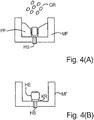
- the holding pin HS or the implant IM is introduced into a mold PF, so that the second portion TB2 is exposed above the collar KR.
- a plastic granulate GR is provided, which is filled after liquefaction by heating in the mold PF.
- the plastic granulate GR is subsequently under heating, for example, in a vacuum, so that the holding element HE is formed in the second partial area TB2.
- the holding element HE is referred to as the abutment portion of the implant IM.
- the temperature to be set is determined by the materials used of the retaining element HE and the retaining pin HS or implant IM. With the use of PEEK and titanium or zirconium dioxide, a temperature of about 380 ° C has proven to be particularly effective in order to achieve that the holding element HE, the holding pin HS on its outer side above the collar KR encloses gapless. This temperature is above the melting point of PEEK but below the temperature range at which degradation of the materials used would begin.
- the step of pressing the plastic granules GR in a temperature range between 240 ° and 450 °, preferably between 380 ° and 400 ° are performed.
- a preheating step may be performed, for example at 650 °.
- the surface in the second portion TB2 can be roughened before pressing.
- the holding element HE forms a gap-free connection with the holding pin HS or implant IM, which withstands very high loads.
- an abutment AB which can absorb very large forces.
- the abutment AB can be used in a dental prosthetic arrangement, wherein the holding element HE of the abutment serves as a support structure for a crown, a bridge or a bridge-like dentures.
- the connection of the dental prosthetic arrangement to the abutment AB can be carried out by means of screwing or gluing.
- an abutment AB for this purpose, in a first step, an abutment AB, as in connection with Fig. 3 described, provided.
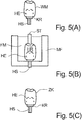
- the abutment AB is provided in the region of the holding element HE with a wax model WM, which in the example shown is intended to represent the future dental crown or individual abutment.
- the abutment AB is introduced together with the wax model WM in a muffle shape MF, which is then provided by means of a suitable filling material FM, to cover the area outside of the wax model WM. While embedding the wax model WM in the Filling material FM is also an Anargen to get access to the area of the wax model WM.
- Fig. 5 (B) schematically indicated by the pin ST.
- the abutment AB comprises a passage DF which completely penetrates the abutment AB in the axial direction.
- the wax model WM begins to melt and burns out
- the porous structure of the filler supports the formation of a cavity HR within the filler FM. Consequently, within the filling material FM, the cavity HR remains as in FIG Fig. 5 (B) is shown.
- the plastic granulate can in turn be made available as a high performance polymer PEEK.
- the PEEK material is mixed with a ceramic additive, for example, to achieve a color matching of the tooth crown.
- the material is heated in the muffle in a preheating oven at 400 ° C, followed by a hot pressing of the granules, wherein the compression in the range around 380 ° C is performed.
- the actual pressing takes place in a vacuum, so that the later tooth crown can be formed without bubbles.
- a dental crown ZK As in Fig. 5 (C) is shown.
- the tooth crown ZK sits on the holding element HE, wherein the retaining pin HS can be used as anchoring point in an implant.
- an abutment AB is selected as the starting point, which corresponds to the in Fig. 1 (A) shown corresponds.
- the abutment AB consequently has no holding element HE.
- the hot pressing with the thermoplastic polymer consequently produces a structure similar to that in US Pat Fig. 5 (C) wherein the enclosing of the retaining pin HS with the thermoplastic polymer is performed in a single step without the prior formation of a retaining element HE.
- the holding element HE attached as Abutmentanteil of PEEK.
- the implant IM Underneath is the implant IM.
- the holding element HE covers in particular the grooves RI above the implant IM, which serve as retentive areas, so that after hot pressing the plastic material of the thermoplastic polymer can withdraw into these areas on cooling.
- the implant IM is made of a non-noble metal, in particular titanium, of a ceramic, in particular aluminum oxide, or of zirconium dioxide.
- this is the holding element HE made of PEEK editable and thus customizable, so that after insertion into a jawbone in Fig. 6 implant shown IM can be used as a structural element for attachment of crowns or dental bridges in dentistry.
- the illustrated embodiment may be referred to as a one-piece, two-phase implant.
- FIG. 7 Another embodiment is in Fig. 7 shown.
- a tooth crown ZK is sprayed directly onto an implant. This procedure directly creates a dental prosthetic element that can be inserted into a jawbone.
- the anchoring element is either as abutment AB according to Fig. 3 or as an implant according to Fig. 6 provided. This is followed by over-pressing or over-spraying of the dental prosthetic components with the thermoplastic polymer.
- the anchoring element according to the invention or the method according to the invention have advantages with respect to the gold and ceramic constructions known in the prior art.
- the cured PEEK proves to be easy to process and has no interaction with other materials. Due to the high load capacity and breaking strength combined with low weight, a very robust dental prosthesis is created. This can be used accurately, reproducibly and free of stress cracks. By additives, such.
- ceramic materials which consists of a high-performance polymer tooth crown ZK is color comparable to the other teeth or crowns and there is no gum irritation on.
- the PEEK high-performance polymer used can take up chewing forces of up to 1,000 MPa, thus ensuring high resistance to breakage at the same time high safety reserves are achieved.
- This material is also biocompatible, as has already been shown in human medicine, for example, in artificial hip replacements, finger joints or heart valves.
- abutment AB according to the invention or the method according to the invention can be used in many dental prosthetic applications. These may include, for example, crown bridges or similar web constructions.
Landscapes
- Health & Medical Sciences (AREA)
- Public Health (AREA)
- Veterinary Medicine (AREA)
- Animal Behavior & Ethology (AREA)
- General Health & Medical Sciences (AREA)
- Oral & Maxillofacial Surgery (AREA)
- Dentistry (AREA)
- Epidemiology (AREA)
- Life Sciences & Earth Sciences (AREA)
- Orthopedic Medicine & Surgery (AREA)
- Engineering & Computer Science (AREA)
- Mechanical Engineering (AREA)
- Chemical & Material Sciences (AREA)
- Composite Materials (AREA)
- Manufacturing & Machinery (AREA)
- Plastic & Reconstructive Surgery (AREA)
- Ceramic Engineering (AREA)
- Dental Prosthetics (AREA)
- Dental Preparations (AREA)
Description
- Die Erfindung betrifft ein Verfahren zum Überpressen eines Abutments oder eines Abutmentanteils eines Implantats mit einer zahnprothetischen Anordnung. Abutments sind aus dem allgemeinen Stand der Technik bekannt und werden auf vielfältige Weise in der Zahnprothetik verwendet. Ein Abutment ist ein Aufbauelement, das zur Befestigung von Kronen oder Zahnbrücken in der Zahnheilkunde dient. Ebenso werden Abutments als Primär- oder Sekundärhalterung von stegartigen oder teleskopartigen zahnprothetischen Anordnungen verwendet.
Ein Abutment weist üblicherweise einen metallischen Stift auf, der beispielsweise in Kombination mit einem Implantat als Verankerungspunkt in einem Kieferknochen vorgesehen ist. Auf der dem Verankerungspunkt gegenüberliegenden Seite wird beispielsweise eine Krone befestigt.
Bekannte Abutments werden üblicherweise aus Titan gefertigt. Nach dem Anfertigen eines Abdrucks der herzustellenden Zahnprothese wird anschließend eine Krone gefertigt, die dann auf das Abutment aufgeklebt oder aufgeschraubt wird.
Implantate sind ebenfalls aus dem allgemeinen Stand der Technik bekannt. Diese weisen auf einer dem Kieferknochen zugewandten Seite eine Schraubverbindung auf, so dass das Implantat im Kiefer verankerbar ist. Auf der gegenüberliegenden Seite wird beispielsweise eine Zahnkrone oder ähnliches aufgebracht. - Aus der
WO 2011/056450 A2 ist ein vorgefertigtes Zahnimplantat bekannt, das ein vorgefertigtes Abutment, das ein subgingivales Ende mit einer Verankerung im Implantat und ein gegenüberliegendes Ende aufweist, wobei das gegenüberliegende Ende permanent mit einem schmelzbaren Dentalmaterial verbunden ist und das Abutment aus einem anderen Material als das schmelzbare Dentalmaterial gefertigt ist. - In der
EP 2 143 398 A1 ist ein aus einem Keramikmaterial bestehendes Zahnimplantat mit einem Implantatkörper zum Verankern in einem Kieferknochen und mit einem in eine Halteaufnahme des Implantatkörpers einsetzbaren und fixierbaren Implantatpfosten beschrieben, dessen aus dem Implantatkörper herausstehender Tragabschnitt zur Befestigung eines Zahnersatzes ausgebildet ist und dessen in der Halteaufnahme fixierbarer Halteabschnitt sowie diese Halteaufnahme jeweils wenigstens in einem Teilbereich in der Einsteckrichtung einander entsprechend konusförmig verjüngt sind. - In der
WO 2011/034780 A1 ist ein Verfahren zur Herstellung einer dentalen Restauration beschrieben. Das Verfahren umfasst das Anbringen eines Abutments zu einem Implantat in dem Mund eines Patienten und das Abtasten zumindest ein Teil des Abutments im Mund des Patienten, um eine digitale Oberflächendarstellung zu erfassen umd ein dreidimensionales digitales Modell der digitalen Oberflächendarstellung zu schaffen, sowie das Bilden einer Restauration aus dem dreidimensionalen digitalen Modell. - In der
US 2007/0031793 A1 wird die Herstellung von provisorischen Kronen beschrieben, um vorübergehend Zahnimplantate wiederherzustellen. Die vorgefertigten provisorischen Kronen sind an den gingivalen Abschnitt der Anschlagvorrichtung eines Zahnimplantats oder Kragen eines Zahnimplantats angepasst. Die vorgefertigte provisorische Implantatkrone wird im allgemeinen als eine hohle Schale ausgeführt.
Bekanntlich treten beim Einsatz von zahnprothetischen Anordnungen oftmals hohe Kräfte in den Verankerungselementen auf, die zu mechanischen Belastungen führen können, so dass eventuell die Klebeverbindungen gelöst werden oder mechanische Schäden auftreten können.
Folglich besteht in der Technik ein Bedarf, oben genannte Nachteile zu überwinden und bekannte Verankerungselemente in Form von Abutments oder Implantaten weiter zu verbessern. - Es ist daher Aufgabe der Erfindung ein Verfahren zum Überpressen eines Abutments anzugeben, das eine weitere Verbesserung bei Belastung erreicht.
- Diese Aufgabe wird durch die Merkmale des unabhängigen Patentanspruchs gelöst. Weitere vorteilhafte Ausgestaltungen der Erfindung sind jeweils Gegenstand der Unteransprüche. Diese können in technologisch sinnvoller Weise miteinander kombiniert werden. Die Beschreibung, insbesondere im Zusammenhang mit der Zeichnung, charakterisiert und spezifiziert die Erfindung zusätzlich.
Es wird ein Verankerungselement für eine zahnprothetische Anordnung geschaffen, das in einem ersten Teilbereich in einem Kieferknochen oder Implantat verankerbar ist, und das geeignet ist, in einem zweiten Teilbereich ein zahnprothetisches Element aufzunehmen oder zu bilden, wobei das Verankerungselement zwischen dem ersten Teilbereich und dem zweiten Teilbereich einen in radialer Richtung vorstehenden Kragen aufweist, der den Umfang des Verankerungselements wenigstens teilweise umschließt, wobei der Bereich oberhalb des Kragens des Verankerungselements wenigstens teilweise vollflächig mit einem thermoplastischen Kunststoffmaterial bedeckt ist. - Demgemäß wird in einem Abutment auf einen Haltestift oder auf ein Implantat beispielsweise mittels Heißpressens ein Halteelement aufgebracht, das als Verbindung zwischen dem Haltestift und einem zahnprothetischen Element, wie z.B. einer Zahnkrone, verwendet wird oder durch entsprechende Formgebung dieses direkt bilden kann. Das zahnprothetische Element kann auf das Halteelement aufgeklebt oder mit dem Abutment oder Implantat durch Schrauben verbunden werden. Aufgrund der zwischenraumfreien Verbindung zwischen dem Halteelement und dem Haltestift ist das Abutment oder das Implantat in der Lage hohe Kräfte aufzunehmen, ohne sich zu lösen oder abzusplittern. Folglich können hohe Kaukräfte aufgenommen werden. Der oberhalb des Kragens angeordnete Teil des Haltestiftes wirkt als zusätzliche Versteifung.
- Das Verankerungselement kann einen in ein Implantat einführbaren Haltestift, der vorzugsweise einen nicht rotationssymmetrischen Querschnitt aufweist, oder ein in einem Kieferknochen verankerbares Implantat umfassen.
- Das Verankerungselement kann im zweiten Teilbereich eine aufgeraute Oberfläche aufweisen.
- Versuche haben gezeigt, dass eine aufgeraute Oberfläche die Verbindung des Halteelements mit dem Haltestift oder dem Implantat mittels Heißpressens fördern kann. Die aufgeraute Oberfläche kann dabei eine Körnung im Bereich von einigen 100 µm aufweisen, wobei die genaue Ausgestaltung von den verwendeten Materialien des Abutments abhängig ist.
- Gemäß einer Ausführungsform der Erfindung ist das Halteelement aus einem thermoplastischen Polymer, vorzugsweise aus PEEK, gefertigt.
- PEEK (abgekürzt für Polyetheretherketon) ist als biokompatibler Werkstoff bei Verwendung in der Medizin im Wesentlichen physiologisch inert und folglich für den Patienten irritationsfrei. Daneben weist PEEK, aber auch andere Hochleistungspolymere, eine hohe Belastbarkeit bezüglich Kaukräften auf, so dass Bruchstabilitäten bis 1000 MPa erreicht werden können. Folglich bietet dieses Material im Vergleich zu einer Lithium-Disilikat-Keramik wesentlich höhere Sicherheitsreserven, was insbesondere bei der Verwendung im Seitenzahnbereich wichtig ist.
- Gemäß einer weiteren Ausführungsform der Erfindung ist der Haltestift oder das Implantat aus einem Nichtedelmetall, vorzugsweise Titan, aus einer Keramik, insbesondere Aluminiumoxid, oder aus Zirconium-Dioxid gefertigt.
- Titan ist im menschlichen Körper zur Verwendung in der Zahnprothetik bestens geeignet. Insbesondere im Zusammenspiel mit PEEK ergeben sich spannungsfreie Abutments, wobei das aus dem thermoplastischen Polymer bestehende Halteelement und der Titan-Haltestift lückenlos aneinander gefügt sind. Der zugrunde liegende physikalische oder chemische Effekt ist jedoch nicht vollständig bekannt. Es zeigt sich überraschenderweise, dass das heißverpresste Polymer mit dem Nichtedelmetall eine besonders stabile Verbindung bildet, die darüber hinaus frei von Rissen und Lücken ist. Eine Vermutung besteht darin, dass sich das auf der Oberfläche des Nichtedelmetalls bildende Metalloxid mit den Polymer-Ketten des Halteelements eine Verbindung eingeht, die dem Abutment besonders leistungsfähige Eigenschaften verleiht. Keramische Materialien wie Aluminiumoxid oder auch Zirconium-Dioxid können ebenfalls verwendet werden.
- Gemäß einer weiteren Ausführungsform der Erfindung weist der Haltestift oder das Implantat auf seiner Außenseite im Bereich des Halteelements eine profilierte Oberfläche auf.
- Eine profilierte Oberfläche bildet retentive Bereiche, so dass sich nach einem Heißverpressen das Kunststoffmaterial des thermoplastischen Polymers beim Abkühlen sich in diese Bereiche zurückziehen kann. Dies unterstützt die vollflächige, also lückenlose Bedeckung des Haltestifts mit dem thermoplastischen Kunststoff.
- Die profilierte Oberfläche kann mehrere in axialer Richtung parallel angeordnete Rippen, vorzugsweise mit einem dreieckförmigen Querschnitt, umfassen.
- Bei dem Verankerungselement kann das thermoplastische Polymer im zweiten Teilbereich so gebildet sein, das sich ein Halteelement ausbildet, so dass das Verankerungselement als Abutment verwendbar ist.
- Das thermoplastische Polymer kann so geformt sein, das im zweiten Teilbereich eine Zahnkrone gebildet ist.
- Das Verankerungselement kann als einstückiges, zwei-phasiges Implantat verwendbar sein.
- Gemäß der Erfindung wird in ihrem zweiten Aspekt ein Verfahren zur Herstellung eines Abutments, oder eines Abutments oder zahnprothetischen Elements auf einem Implantat angegeben, bei dem folgende Schritte ausgeführt werden:
- Bereitstellen eines Haltestifts oder Implantats mit einem in radialer Richtung vorstehenden Kragen, der den Umfang des Haltestifts oder Implantats wenigstens teilweise umschließt, wobei ein erster Teilbereich des Haltestifts oder Implantats unterhalb des Kragens als Verankerung ausgebildet ist;
- Einbringen des Haltestifts oder Implantats in eine Pressform, so dass ein zweiter Teilbereich oberhalb des Kragens freigelegt ist;
- Auffüllen der Pressform mit einem Kunststoffgranulat; und
- Verpressen des Kunststoffgranulats unter Erhitzen, so dass im zweiten Teilbereich ein Halteelement oder Zahnkrone gebildet wird, wobei der Kragen und der Haltestift oder das Implantat im zweiten Teilbereich wenigstens teilweise vollflächig bedeckt sind.
- Gemäß einer weiteren Ausführungsform des Verfahrens wird das Kunststoffmaterial als ein thermoplastisches Hochleistungspolymer, vorzugsweise PEEK, bereitgestellt.
- Gemäß einer weiteren Ausführungsform des Verfahrens ist der Haltestift aus einem Nichtedelmetall, vorzugsweise Titan, aus einer Keramik, insbesondere Aluminiumoxid, oder aus Zirconium-Dioxid gefertigt.
- Gemäß einer weiteren Ausführungsform des Verfahrens wird der Schritt des Verpressens des Kunststoffmaterials unter Erhitzen in einem Temperaturbereich zwischen 240°C und 450°C, vorzugsweise im Bereich zwischen 380°C und 400°C, durchgeführt.
- Gemäß einer weiteren Ausführungsform des Verfahrens wird vor dem Schritt des Auffüllens der Muffelform mit dem Kunststoffmaterial ein Vorwärmschritt, vorzugsweise zwischen 600°C und 650°C, durchgeführt.
- Gemäß einer weiteren Ausführungsform des Verfahrens wird der Schritt des Verpressens unter Vakuum durchgeführt.
- Außerdem wird eine zahnprothetische Anordnung angegeben, die ein oben beschriebenes Verankerungselement aufweist, wobei das Haltelement des Abutments oder des Implantats als Trägerstruktur dient.
- Bei der Zahnprothetische Anordnung kann eine Krone, eine Brücke oder ein stegartiger Zahnersatz mit einem oder mehreren Abutments verbunden sein.
- Die Verbindung mit dem einem oder mehreren Abutments kann durch Verkleben oder Verschrauben herstellbar sein.
- Des Weiteren wird ein Verfahren zum Überpressen eines Abutments oder eines Abutmentanteils eines Implantats mit einer zahnprothetischen Anordnung, bei dem folgende Schritte ausgeführt werden:
- Bereitstellen eines Abutments oder eines Implantats mit einem Halteelement;
- Einbringen des Abutments oder des Implantats in eine Muffelform;
- Bereitstellen eines Wachsmodells;
- Einbetten des Wachsmodells in der Muffelform;
- Auswachsen der Muffelform;
- Auffüllen der Muffelform mit einem Granulat eines thermoplastischen Polymers; und
- Heißverpressen des Granulats, um die zahnprothetischen Anordnung mit dem Abutment oder dem Implantat zu schaffen.
- Des Weiteren kann bei diesem Verfahren das Hochleistungs-Polymer PEEK umfassen.
- Das Hochleistungs-Polymer kann auch mit einem Keramikzusatz vermischt sein.
- Schließlich wird ein Verfahren zur thermoplastischen Überpressung oder Überspritzung von zahnprothetischen Konfektionsteilen mit einem oben beschriebenen Verankerungselement angegeben, bei dem folgende Schritte ausgeführt werden:
- Bereitstellen eines Abutments oder eines Implantats mit einem Halteelement als zahnprothetische Konfektionsteile; und
- Überpressung oder Überspritzung der zahnprothetischen Konfektionsteile mit einem thermoplastischen Polymer.
- Nachfolgend werden einige Ausführungsbeispiele anhand der Zeichnungen näher erläutert. Es zeigen:
-
Fig. 1A einen Haltestift als Verankerungselement in einer Seitenansicht, -
Fig. 1B ein als Verankerungselement Implantat in einer Seitenansicht, -
Fig. 2 den Haltestift ausFig. 1A in einer Draufsicht, -
Fig. 3 ein erfindungsgemäßes Verankerungselement in einer Seitenansicht, -
Fig. 4 eine Vorrichtung zur Durchführung eines erfindungsgemäßen Verfahrens, -
Fig. 5 eine weitere Vorrichtung zur Durchführung eines erfindungsgemäßen Verfahrens, -
Fig. 6 ein weiteres erfindungsgemäßes Verankerungselement in einer Seitenansicht, und -
Fig. 7 ein weiteres erfindungsgemäßes Verankerungselement in einer Seitenansicht. -
Fig. 1(A) zeigt einen Haltestift HS als Verankerungselement für ein Abutment AB in einer perspektivischen Seitenansicht. Der Haltestift HS weist einen in radialer Richtung vorstehenden Kragen KR auf, der den Umfang des Haltestifts HS wenigstens teilweise umschließt. Unterhalb des Kragens KR ist ein erster Teilbereich TB1 ausgebildet, der als Verankerung in einem inFig. 1(A) nicht dargestellten Implantat dient. Oberhalb des Kragens KR befindet sich der zweite Teilbereich TB2. Innerhalb des zweiten Teilbereichs TB2 weist der Haltestift HS an seiner Außenseite eine Profilierung auf. Diese ist inFig. 1(A) als eine Anordnung von mehreren in axialer Richtung parallel angeordneten Rippen RI gezeigt, die den Umfang des Haltestifts HS im zweiten Teilbereich TB2 umschließen. Die Rippen RI weisen beispielsweise einen dreiecksförmigen Querschnitt auf, wobei andere Ausgestaltungen ebenfalls möglich sind. - In
Fig. 2 ist der Haltestift HS ausFig. 1(A) in einer Querschnittsansicht gezeigt. Die Querschnittsansicht derFig. 2 entspricht dabei einer Ansicht vom Ende des zweiten Teilbereichs TB2 her. Wie manFig. 2 entnehmen kann, ist als der Durchmesser der Rippen RI kleiner als der des Kragens KR. Desweiteren sind die Rippen RI in mehreren Bereichen BE1, BE2, BE3 und BE4 mit einem verringerten Durchmesser ausgeführt, so dass sich insgesamt ein nicht rotationssymmetrischer Querschnitt des Haltestifts HS ergibt. Es sei angemerkt, dass der nicht rotationssymmetrische Querschnitt des Haltestifts HS auf vielfältige Weise erreicht werden kann, beispielsweise mit einer unterschiedlichen Anzahl von Bereichen mit verringertem Durchmesser, aber auch mittels Bereichen mit vergrößertem Durchmesser oder einer anderen Positionierung dieser Bereiche. - Ebenfalls in
Fig. 2 ist gezeigt, dass das Abutment AB eine Durchführung DF aufweist, die das Abutment AB entlang seiner Längsachse vollständig durchdringt. Die Durchführung DF kann dazu verwendet werden, den Haltestift HS nach dem Einbringen in ein Implantat beispielsweise mittels einer Schraubverbindung zu arretieren. -
Fig. 1 (B) zeigt ein Implantat IM als Verankerungselement VE in einer perspektivischen Seitenansicht. Das Implantat IM weist ebenfalls den in radialer Richtung vorstehenden Kragen KR auf, der den Umfang des Haltestifts HS wenigstens teilweise umschließt. Unterhalb des Kragens KR ist im ersten Teilbereich TB1 das schraubenförmige Implantat ausgebildet, das als Verankerung in einem inFig. 1 (B) nicht dargestellten Kieferknochen dient. Oberhalb des Kragens KR befindet sich der zweite Teilbereich TB2. Innerhalb des zweiten Teilbereichs TB2 weist der Haltestift HS an seiner Außenseite die Profilierung auf. Diese ist inFig. 1 (B) wiederum als eine Anordnung von mehreren in axialer Richtung parallel angeordneten Rippen RI gezeigt, die den Umfang des Haltestifts HS im zweiten Teilbereich TB2 umschließen. - In
Fig. 3 ist das Abutment AB gezeigt, das ausgehend von dem Haltestift HS gemäßFig. 1(A) und2 weiterentwickelt wurde, um ein sogenanntes Hybrid-Abutment zu bilden. Hybrid-Abutments weisen neben dem Haltestift HS ein zusätzliches Element auf, das als Basis für eine zahnprothetische Anordnung, wie z.B. eine Krone, herangezogen werden kann.
WieFig. 3 zu entnehmen ist, ist oberhalb des Kragens KR ein Halteelement HE angebracht, das den Kragen KR und den Haltestift HS teilweise bedeckt. Das Halteelement HE ist aus einem thermoplastischen Polymer, insbesondere PEEK gefertigt. Das Halteelement HE bedeckt dabei insbesondere die Rillen RI, die als retentive Bereiche dienen, so dass nach einem Heißverpressen das Kunststoffmaterial des thermoplastischen Polymers beim Abkühlen sich in diese Bereiche zurückziehen kann.
Der Haltestift HS ist aus einem Nichtedelmetall, insbesondere Titan, aus einer Keramik, insbesondere Aluminiumoxid, oder aus Zirconium-Dioxid gefertigt. Das inFig. 3 gezeigte Abutment AB kann als Aufbauelement zur Befestigung von Kronen, Zahnbrücken oder Implantate in der Zahnheilkunde verwendet werden. - Unter Bezugnahme auf
Fig. 4 wird im Folgenden ein Verfahren zur Herstellung eines Abutments AB näher erläutert. Dabei wird in einem ersten Schritt als Verankerungselement ein Haltestift, wie im Zusammenhang mitFig. 1 (A) oder ein Implantat IM wie im Zusammenhang mitFig. 1 (B) beschrieben, bereitgestellt. Der Haltestift HS oder das Implantat IM wird in eine Pressform PF eingebracht, so dass der zweite Teilbereich TB2 oberhalb des Kragens KR frei gelegt ist. Nach einem Ausformungsschritt wird ein Kunststoffgranulat GR bereitgestellt, das nach Verflüssigung durch Erwärmen in die Pressform PF eingefüllt wird. Das Kunststoffgranulat GR wird anschließend unter Erhitzen, beispielsweise im Vakuum, verpresst, so dass im zweiten Teilbereich TB2 das Halteelement HE gebildet wird. Das Halteelement HE wird als Abutmentanteil des Implantats IM bezeichnet. - Die einzustellende Temperatur wird von den verwendeten Materialen des Halteelements HE und des Haltestifts HS beziehungsweise Implantats IM bestimmt. Bei der Verwendung von PEEK und Titan oder Zirconium-Dioxid hat sich eine Temperatur von ungefähr 380°C als besonders wirkungsvoll herausgestellt, um zu erreichen, dass das Halteelement HE den Haltestift HS auf seiner Außenseite oberhalb des Kragens KR lückenlos umschließt. Diese Temperatur ist oberhalb des Schmelzpunktes von PEEK aber unterhalb desjenigen Temperaturbereichs, bei dem eine Degradierung der verwendeten Materialien beginnen würde.
- Allgemein kann der Schritt des Verpressens des Kunststoffgranulats GR in einem Temperaturbereich zwischen 240° und 450°, vorzugsweise zwischen 380° und 400° durchgeführt werden.
- Vor dem eigentlichen Schritt des Verpressens kann ein Vorwärmschritt beispielsweise bei 650° durchgeführt werden. Ebenso kann die Oberfläche im zweiten Teilbereich TB2 vor dem Verpressen aufgeraut werden.
- Wie sich gezeigt hat, bildet sich bei der vorbeschriebenen Verfahrensführung das Halteelement HE mit dem Haltestift HS beziehungsweise Implantat IM eine lückenlose Verbindung, die sehr großen Belastungen Stand hält.
- Wie bereits erwähnt, hat sich bei der Verwendung von PEEK für das Halteelement HE und Titan, Keramik oder Zirconium-Dioxid für den Haltestift HS insbesondere eine Temperatur des Heißverpressens von 380° als besonders wirkungsvoll herausgestellt. Dabei dienen die Rillen RI als retentive Bereiche die nach dem Erkalten des Kunststoffmaterials ein Aufschrumpfen begünstigen. Während des Heißverpressens verbinden sich vermutlich Molekülketten des PEEK mit oberflächlich oxidiertem Titan des Haltestifts HS beziehungsweise Implantats IM. Diese chemische Verbindung unterstützt das Anhaften des Kunststoffmaterials über dem Haltestift HS beziehungsweise Implantat IM, so dass die oben beschriebene lückenlose Umschließung erreicht wird.
- Gemäß diesem Verfahren ist es möglich, ein Abutment AB zu bilden, das sehr große Kräfte aufnehmen kann. Das Abutment AB kann in einer zahnprothetischen Anordnung Verwendung finden, wobei das Haltelement HE des Abutments als Trägerstruktur für eine Krone, eine Brücke oder einen stegartigen Zahnersatz dient. Die Verbindung der zahnprothetischen Anordnung zu dem Abutment AB kann mittels Verschraubens oder Verklebens durchgeführt werden. Ebenso ist es möglich, ein Implantat IM zu bilden, bei dem der Abutmentanteil durch das Halteelement HE gebildet wird.
- Unter Bezugnahme auf die
Fig. 5 (A) bis 5 (C) wird im Folgenden ein Verfahren Verfahren zum Überpressen eines Abutments oder eines Abutmentanteils eines Implantats mit einer zahnprothetischen Anordnung erläutert. - Dazu wird in einem ersten Schritt ein Abutment AB, wie im Zusammenhang mit
Fig. 3 beschrieben, bereit gestellt. Das Abutment AB wird im Bereich des Halteelement HE mit einem Wachsmodell WM versehen, das in dem gezeigten Beispiel die spätere Zahnkrone oder individuelles Abutment repräsentieren soll. Das Abutment AB wird zusammen mit dem Wachsmodell WM in eine Muffelform MF eingebracht, die anschließend mittels eines geeigneten Füllmaterials FM versehen wird, um den Bereich außerhalb des Wachsmodells WM abzudecken. Während des Einbettens der des Wachsmodells WM in dem Füllmaterial FM erfolgt auch ein Anstiften, um einen Zugang zu dem Bereich des Wachsmodells WM zu erhalten. - Das Anstiften ist in
Fig. 5 (B) schematisch durch den Stift ST angedeutet. Hierbei ist es erwähnenswert, dass das Abutment AB eine Durchführung DF umfasst, die das Abutment AB in axialer Richtung vollständig durchdringt. Durch Erhitzen erfolgt ein sogenanntes Auswachsen, wobei das Wachsmodell WM zu schmelzen beginnt und ausbrennt, wobei die poröse Struktur des Füllmaterials die Bildung eines Hohlraums HR innerhalb des Füllmaterials FM unterstützt. Folglich verbleibt innerhalb des Füllmaterials FM der Hohlraum HR, wie inFig. 5 (B) gezeigt ist. - Anschließend erfolgt ein Füllen der Muffelform MF mittels eines Kunststoffgranulats, das zur Vorbereitung des Pressens mittels eines nicht gezeigten Stempels komprimiert wird. Das Kunststoffgranulat kann wiederum als Hochleistungspolymer PEEK bereit gestellt werden. Zusätzlich ist es denkbar, dass das PEEK-Material mit einem Keramikzusatz vermischt wird, um beispielsweise eine Farbanpassung der Zahnkrone zu erzielen.
- Nachdem die Muffelform MF mit dem Granulat gefüllt wurde, erfolgt das Aufheizen des Materials in der Muffel in einem Vorwärmofen bei 400°C, danach erfolgt ein Heißverpressen des Granulats, wobei die Verpressung im Bereich um die 380° C durchgeführt wird. Das eigentliche Verpressen erfolgt dabei im Vakuum, so dass die spätere Zahnkrone blasenfrei gebildet werden kann.
- Nach dem Abkühlen erhält man nun eine Zahnkrone ZK, wie in
Fig. 5 (C) gezeigt ist. Die Zahnkrone ZK sitzt dabei auf dem Halteelement HE, wobei der Haltestift HS als Verankerungspunkt in einem Implantat herangezogen werden kann. - In einer anderen Ausführung des erfindungsgemäßen Verfahrens wird als Ausgangspunkt ein Abutment AB gewählt, das dem in
Fig. 1(A) gezeigtem entspricht. Das Abutment AB weist folglich kein Halteelement HE auf. Durch das Heißverpressen mit dem thermoplastischen Polymer wird folglich eine Struktur erzeugt, die der inFig. 5(C) entspricht, wobei das Umschließen des Haltestifts HS mit dem thermoplastischen Polymer in einem einzigen Schritt ohne vorherige Bildung eines Haltelements HE durchgeführt wird. - Unter Bezugnahme auf
Fig. 6 wird eine weitere Ausführungsform der Erfindung erläutert. - Wie
Fig. 6 zu entnehmen ist, ist oberhalb des Kragens KR wiederum das Halteelement HE als Abutmentanteil aus PEEK angebracht. Darunter befindet sich das Implantat IM. Das Halteelement HE bedeckt dabei oberhalb des Implantats IM insbesondere die Rillen RI, die als retentive Bereiche dienen, so dass nach einem Heißverpressen das Kunststoffmaterial des thermoplastischen Polymers beim Abkühlen sich in diese Bereiche zurückziehen kann. Das Implantat IM ist aus einem Nichtedelmetall, insbesondere Titan, aus einer Keramik, insbesondere Aluminiumoxid, oder aus Zirconium-Dioxid gefertigt. - Nach Fertigstellung ist das das Halteelement HE aus PEEK bearbeitbar und damit individualisierbar, so dass nach dem Einsetzen in einen Kieferknochen das in
Fig. 6 gezeigte Implantat IM als Aufbauelement zur Befestigung von Kronen oder Zahnbrücken in der Zahnheilkunde verwendet werden kann. Die gezeigte Ausführungsform kann als einstückiges, zwei-phasiges Implantat bezeichnet werden. - Das Herstellungsverfahren folgt dabei denn in Zusammenhang mit
Fig. 4 beschriebenem, wobei anstelle der Muffelform MF eine Stahlform zum Einsatz kommen kann, um hygienischen Anforderungen während des Einsetzens des Implantats IM in einen Kieferknochen zu genügen. - Eine weitere Ausführungsform ist in
Fig. 7 gezeigt. Dabei wird eine Zahnkrone ZK direkt auf ein Implantat aufgespritzt. Diese Vorgehensweise erzeugt unmittelbar ein zahnprothetisches Element, das in einen Kieferknochen eingesetzt werden kann. - Des Weiteren ist es möglich, die Erfindung in einem Verfahren zur thermoplastischen Überpressung oder Überspritzung von zahnprothetischen Konfektionsteilen zu nutzen. Dabei wird das Verankerungselement entweder als Abutment AB gemäß
Fig. 3 oder als Implantat gemäßFig. 6 bereitgestellt. Anschließend erfolgt ein Überpressen oder Überspritzen der zahnprothetischen Konfektionsteile mit dem thermoplastischen Polymer. - Das erfindungsgemäße Verankerungselement bzw. das erfindungsgemäße Verfahren weisen Vorteile bezüglich der im Stand der Technik bekannten Gold- und Keramikkonstruktionen auf. Zum einen erweist sich das ausgehärtete PEEK als leicht zu bearbeiten und weist keinerlei Wechselwirkungen mit anderen Materialien auf. Aufgrund der hohen Belastbarkeit und Bruchfestigkeit bei gleichzeitig geringem Gewicht wird eine sehr robuste Zahnprothese geschaffen. Diese kann passgenau, reproduzierbar und frei von Spannungsrissen eingesetzt werden. Durch Zusätze, wie z. B. Keramikmaterialien, ist die aus einem Hochleistungspolymer bestehende Zahnkrone ZK farblich an die übrigen Zähne oder Zahnkronen angleichbar und es treten keinerlei Zahnfleischirritationen auf.
- Es hat sich gezeigt, dass das verwendete Hochleistungspolymer PEEK Kaukräfte bis zu 1.000 MPa aufnehmen kann, so dass eine hohe Bruchstabilität bei gleichzeitig hohen Sicherheitsreserven erreicht wird. Dieses Material ist darüber hinaus biokompatibel, wie sich in der Humanmedizin beispielsweise bei künstlichen Hüftprothesen, Fingergelenken oder Herzklappen bereits gezeigt hat.
- Das gezeigte Beispiel mit einer Zahnkrone ZK dient lediglich der Veranschaulichung der Erfindung. Es versteht sich von selbst, dass das erfindungsgemäße Abutment AB bzw. das erfindungsgemäße Verfahren in vielerlei zahnprothetischen Anwendungen eingesetzt werden kann. Diese können beispielsweise Kronenbrücken oder ähnliche Stegkonstruktionen umfassen.
Zahnprothetische Anordnungen können zum einen direkt als sogenanntes Implantat in einem Kieferknochen fixiert werden oder über einen Haltestift in ein bereits im Kieferknochen verankertes Implantat befestigt werden. Beide Ausführungsformen, das heißt sowohl das Implantat als auch der Haltestift werden im Folgenden als Verankerungselement bezeichnet. Die Ausführung mit Haltestift wird nachfolgend in
Claims (12)
- Verfahren zum Überpressen eines Abutments oder eines Abutmentanteils eines Implantats mit einer zahnprothetischen Anordnung, bei dem folgende Schritte ausgeführt werden:- Bereitstellen eines Abutments (AB) oder eines Implantats (IM) mit einem Halteelement (HE);- Bereitstellen eines Wachsmodells (WM), so dass das Abutment (AB) oder Implantat (IM) im Bereich des Halteelements (HE) mit dem Wachsmodell versehen wird;- Einbringen des Abutments (AB) oder des Implantats (IM) in eine Muffelform (MF);- Einbetten des Wachsmodells (WM) in der Muffelform (MF);- Auswachsen der Muffelform (MF);- Auffüllen der Muffelform (MF) mit einem Granulat eines thermoplastischen Polymers; und- Heißverpressen des Granulats, um die zahnprothetische Anordnung (ZK) mit dem Abutment (AB) oder dem Implantat (IM) zu schaffen.
- Verfahren nach Anspruch 1, bei dem als thermoplastisches Polymer PEEK verwendet wird.
- Verfahren nach Anspruch 1 oder 2, bei dem das thermoplastische Polymer mit einem Keramikzusatz vermischt ist.
- Verfahren nach einem der Ansprüche 1 bis 3, bei dem das Abutment (AB) oder der Abutmentanteil des Implantats (IM) als Verankerungselement bereitgestellt wird, das in einem ersten Teilbereich (TB1) in einem Kieferknochen oder Implantat verankerbar ist, und das geeignet ist, in einem zweiten Teilbereich (TB2) ein zahnprothetisches Element (ZK) aufzunehmen oder zu bilden, wobei das Verankerungselement zwischen dem ersten Teilbereich (TB1) und dem zweiten Teilbereich (TB2) einen in radialer Richtung vorstehenden Kragen (KR) aufweist, der den Umfang des Verankerungselements wenigstens teilweise umschließt, wobei der Bereich oberhalb des Kragens (KR) des Verankerungselements wenigstens teilweise vollflächig mit dem thermoplastischen Kunststoffmaterial bedeckt ist.
- Verfahren nach einem der Ansprüche 1 bis 4, bei dem das Abutment (AB) oder das Implantat (IM) aus einem Nichtedelmetall, vorzugsweise Titan oder einer Titanlegierung, aus einer Keramik, insbesondere Aluminiumoxid, oder aus Zirconium-Dioxid, oder aus einem dentaltauglichen Material gefertigt wird.
- Verfahren nach einem der Ansprüche 1 bis 5, bei dem der Schritt des Verpressens des Kunststoffgranulates (GR) zum Aufpressen des Abutmentanteils auf dem Implantat (IM) oder dem Abutment (AB) unter Erhitzen in einem Temperaturbereich zwischen 240°C und 450°C, vorzugsweise im Bereich zwischen 380°C und 400°C, durchgeführt wird.
- Verfahren nach einem der Ansprüche 1 bis 6, bei dem vor dem Schritt des Auffüllens der Muffelform (MF) mit dem Kunststoffgranulat (GR) ein Vorwärmschritt, vorzugsweise zwischen 600°C und 650°C, durchgeführt wird.
- Verfahren nach einem der Ansprüche 1 bis 7, bei dem der Schritt des Verpressens unter Vakuum durchgeführt wird.
- Verfahren nach Anspruch 1 bis 8, bei dem das Verankerungselement einen in ein Implantat einführbaren Haltestift (HS), der vorzugsweise einen nicht rotationssymmetrischen Querschnitt aufweist, oder ein in einem Kieferknochen verankerbares Implantat (IM) umfasst.
- Verfahren nach Anspruch 9, bei dem das Verankerungselement im zweiten Teilbereich (TB2) eine aufgeraute Oberfläche aufweist.
- Verfahren nach einem der Ansprüche 9 oder 10, bei dem das Verankerungselement auf seiner Außenseite im zweiten Teilbereich (TB2) eine profilierte Oberfläche als retentiven Bereich aufweist.
- Verfahren nach Anspruch 11, bei dem die profilierte Oberfläche mehrere in axialer Richtung parallel angeordnete Rippen (RI), vorzugsweise mit einem dreieckförmigen Querschnitt, umfasst.
Applications Claiming Priority (2)
| Application Number | Priority Date | Filing Date | Title |
|---|---|---|---|
| DE102013100529.2A DE102013100529A1 (de) | 2013-01-18 | 2013-01-18 | Verankerungselement und Verfahren zur Herstellung |
| PCT/EP2014/050681 WO2014111413A1 (de) | 2013-01-18 | 2014-01-15 | Verankerungselement und verfahren zur herstellung |
Publications (2)
| Publication Number | Publication Date |
|---|---|
| EP2945563A1 EP2945563A1 (de) | 2015-11-25 |
| EP2945563B1 true EP2945563B1 (de) | 2018-10-17 |
Family
ID=49998251
Family Applications (1)
| Application Number | Title | Priority Date | Filing Date |
|---|---|---|---|
| EP14700853.6A Active EP2945563B1 (de) | 2013-01-18 | 2014-01-15 | Verfahren zur herstellung eines verankerungselements |
Country Status (8)
| Country | Link |
|---|---|
| US (2) | US20150351875A1 (de) |
| EP (1) | EP2945563B1 (de) |
| JP (1) | JP2016507291A (de) |
| KR (1) | KR102260327B1 (de) |
| CN (1) | CN104968296B (de) |
| DE (1) | DE102013100529A1 (de) |
| IL (1) | IL239949B (de) |
| WO (1) | WO2014111413A1 (de) |
Families Citing this family (17)
| Publication number | Priority date | Publication date | Assignee | Title |
|---|---|---|---|---|
| WO2015189647A1 (en) | 2014-06-13 | 2015-12-17 | Vergoullis Loannis | Molds for custom dental implant abutments and impression posts |
| US10639132B2 (en) * | 2014-09-12 | 2020-05-05 | Italo Lozada | Dental prosthesis |
| WO2016132345A1 (en) * | 2015-02-20 | 2016-08-25 | Mishel Weshler | Method, system, abutment and apparatus for dental and over implants treatment |
| ES2723399T3 (es) * | 2015-09-28 | 2019-08-27 | Coltene/Whaledent Ag | Procedimiento para producir bloques odontológicos de material compuesto |
| JP7046076B2 (ja) * | 2016-09-27 | 2022-04-01 | ヴァロック アーゲー | 歯科用修復物を歯科用インプラントに連結するためのシステム |
| KR101869348B1 (ko) * | 2017-07-04 | 2018-06-20 | (주) 코웰메디 | 임플란트 고정체의 제조방법 및 그에 의한 임플란트 고정체 |
| GR20170100383A (el) | 2017-08-21 | 2019-04-22 | Vp Innovato Holdings Ltd | Πυρηνας οδοντικου κολοβωματος και μεθοδος για την κατασκευη ενος οδοντικου κολοβωματος |
| KR101831612B1 (ko) * | 2017-11-07 | 2018-02-26 | 백승관 | 일체형 타입의 치과용 임플란트 |
| DE102017129176A1 (de) * | 2017-12-07 | 2019-06-13 | Bredent Gmbh & Co. Kg | Zahnprothetische Anordnung und Verfahren zur Herstellung einer zahnprothetischen Anordnung |
| KR101898413B1 (ko) * | 2018-04-16 | 2018-09-12 | 고경훈 | 팩톤을 이용한 임플란트용 어버트먼트 및 그 제조방법 |
| KR102227070B1 (ko) * | 2018-08-24 | 2021-03-17 | 주식회사 올뎃덴탈 | 치과용 폴리머 어버트먼트의 제조방법 |
| EP3659574A1 (de) * | 2018-11-29 | 2020-06-03 | Ivoclar Vivadent AG | Verfahren zur herstellung eines zirkonoxid-rohlings |
| WO2020157045A1 (en) * | 2019-01-29 | 2020-08-06 | Valoc Ag | Abutment arrangement and dental restoration kit |
| EP3725262B1 (de) * | 2019-04-18 | 2022-11-02 | Ivoclar Vivadent AG | Dentales ausbettverfahren sowie muffel |
| KR102146627B1 (ko) * | 2019-05-26 | 2020-08-20 | 권혁하 | Pfm 크라운 임플란트 제조 방법 |
| USD1043324S1 (en) * | 2021-03-05 | 2024-09-24 | M3 Health Industria E Comércio De Produtos Médicos, Odontológicos E Correlatos S.A. | Dental implant device |
| TWI746408B (zh) * | 2021-05-20 | 2021-11-11 | 浩鋒 關 | 可增進穩固性的牙植體 |
Citations (4)
| Publication number | Priority date | Publication date | Assignee | Title |
|---|---|---|---|---|
| US20070031793A1 (en) * | 2005-08-03 | 2007-02-08 | Kelley Casement | Provisional crown for dental implants |
| EP2143398A1 (de) * | 2008-07-12 | 2010-01-13 | Gerd Axel Dr. Walther | Zahnimplantat mit elastischem Zwischenelement |
| WO2011034780A1 (en) * | 2009-09-15 | 2011-03-24 | 3M Innovative Properties Company | Dental implant abutments and methods of use |
| WO2011056450A2 (en) * | 2009-10-28 | 2011-05-12 | 3M Innovative Properties Company | Dental implant articles and methods |
Family Cites Families (27)
| Publication number | Priority date | Publication date | Assignee | Title |
|---|---|---|---|---|
| US3905106A (en) * | 1970-09-08 | 1975-09-16 | Policlinica De Stomatologie Pr | Method for fabricating dental bridges dental crowns and corono-radicular retainers |
| SE414399B (sv) * | 1976-03-16 | 1980-07-28 | Hans Scheicher | Keramiskt material for anvendning inom medicinen, i synnerhet for framstellning av implantat, fremst odontologiska implantat samt sett for framstellning av materialet |
| EP0525210A4 (en) * | 1991-02-20 | 1993-07-28 | Tdk Corporation | Composite bio-implant and production method therefor |
| AU683050B2 (en) * | 1993-06-24 | 1997-10-30 | Dentsply Gmbh | Dental prosthesis |
| US6485849B2 (en) * | 1994-05-31 | 2002-11-26 | Tec Ventures, Inc. | Method for molding dental restorations and related apparatus |
| KR19990087401A (ko) * | 1996-02-29 | 1999-12-27 | 키이스 디 | 단일 치아 복구 시스템 |
| FI972890A (fi) * | 1997-07-08 | 1999-01-09 | Bioxid Oy | Uusi muovipohjainen komposiitti ja sen käytt¦ |
| US6116070A (en) * | 1998-11-11 | 2000-09-12 | Advanced Research And Technology Institute | Superplastically-formed prosthetic components, and equipment for same |
| US6669476B2 (en) * | 2000-06-27 | 2003-12-30 | David Michael Prestipino | Nanophase dental prosthetics and method |
| US20060046229A1 (en) * | 2004-08-26 | 2006-03-02 | Teich Thomas J | Dental implant |
| GB2424223C (en) * | 2005-03-07 | 2011-02-02 | Massachusetts Inst Technology | Biomaterial. |
| DE102005016939A1 (de) * | 2005-04-12 | 2006-10-19 | Vekörrer, Franz | Verfahren zur Herstellung von Dentalformteilen |
| US20070015110A1 (en) * | 2005-05-26 | 2007-01-18 | Zimmer Dental, Inc. | Prosthetic dental device |
| DE102006033794B3 (de) * | 2006-07-19 | 2008-03-06 | BEGO Bremer Goldschlägerei Wilh. Herbst GmbH & Co. KG | Elementesatz zur Herstellung einer dentalen Prothese, System zur Herstellung einer dentalen Prothese oder eines Elementesatzes sowie entsprechende Herstellverfahren |
| EP2068758A4 (de) * | 2006-09-25 | 2012-11-14 | Orthovita Inc | Bioaktive tragende verbundstoffe |
| ATE544476T1 (de) * | 2007-04-10 | 2012-02-15 | Zimmer Inc | Antioxidans-stabilisiertes vernetztes ultrahochmolekulares polyethylen für anwendungen in medizinprodukten |
| CN201112665Y (zh) * | 2007-08-28 | 2008-09-10 | 富士康(昆山)电脑接插件有限公司 | 电连接器组件 |
| GB0805052D0 (en) * | 2008-03-19 | 2008-04-16 | 3M Innovative Properties Co | A method for making a dental blank, a press and a system for making dental blanks |
| US20100145393A1 (en) * | 2008-12-05 | 2010-06-10 | Medicinelodge, Inc. | Medical and dental porous implants |
| US20110287382A1 (en) * | 2009-02-12 | 2011-11-24 | Johnson Ryan E | Methods of making and using dental articles for tooth implants and preformed dental articles |
| US8609127B2 (en) * | 2009-04-03 | 2013-12-17 | Warsaw Orthopedic, Inc. | Medical implant with bioactive material and method of making the medical implant |
| WO2011072212A2 (en) * | 2009-12-11 | 2011-06-16 | Difusion Technologies, Inc. | Method of manufacturing antimicrobial implants of polyetheretherketone |
| DE102011001403A1 (de) * | 2011-03-18 | 2012-09-20 | Frank-Peter Spahn | Zahnimplantat und Verfahren zur Herstellung oder zur Bearbeitung eines Zahnimplantats |
| US20130017511A1 (en) * | 2011-07-15 | 2013-01-17 | Shofu, Inc. | Implant fixture |
| EP3799826B1 (de) * | 2011-07-27 | 2024-05-15 | Abracadabra Implants Ltd | Vorrichtung zur prosthodontischen wiederherstellung |
| WO2013059939A1 (en) * | 2011-10-26 | 2013-05-02 | Permatooth Inc. | Dental replacement mounting system |
| US8708033B2 (en) * | 2012-08-29 | 2014-04-29 | General Electric Company | Calcium titanate containing mold compositions and methods for casting titanium and titanium aluminide alloys |
-
2013
- 2013-01-18 DE DE102013100529.2A patent/DE102013100529A1/de active Pending
-
2014
- 2014-01-15 KR KR1020157020763A patent/KR102260327B1/ko active IP Right Grant
- 2014-01-15 CN CN201480005035.2A patent/CN104968296B/zh active Active
- 2014-01-15 EP EP14700853.6A patent/EP2945563B1/de active Active
- 2014-01-15 WO PCT/EP2014/050681 patent/WO2014111413A1/de active Application Filing
- 2014-01-15 US US14/761,691 patent/US20150351875A1/en not_active Abandoned
- 2014-01-15 JP JP2015553065A patent/JP2016507291A/ja active Pending
-
2015
- 2015-07-15 IL IL239949A patent/IL239949B/en active IP Right Grant
-
2018
- 2018-12-12 US US16/217,795 patent/US20190175309A1/en not_active Abandoned
Patent Citations (4)
| Publication number | Priority date | Publication date | Assignee | Title |
|---|---|---|---|---|
| US20070031793A1 (en) * | 2005-08-03 | 2007-02-08 | Kelley Casement | Provisional crown for dental implants |
| EP2143398A1 (de) * | 2008-07-12 | 2010-01-13 | Gerd Axel Dr. Walther | Zahnimplantat mit elastischem Zwischenelement |
| WO2011034780A1 (en) * | 2009-09-15 | 2011-03-24 | 3M Innovative Properties Company | Dental implant abutments and methods of use |
| WO2011056450A2 (en) * | 2009-10-28 | 2011-05-12 | 3M Innovative Properties Company | Dental implant articles and methods |
Also Published As
| Publication number | Publication date |
|---|---|
| IL239949B (en) | 2020-09-30 |
| DE102013100529A1 (de) | 2014-07-24 |
| CN104968296A (zh) | 2015-10-07 |
| WO2014111413A1 (de) | 2014-07-24 |
| EP2945563A1 (de) | 2015-11-25 |
| JP2016507291A (ja) | 2016-03-10 |
| KR20150109382A (ko) | 2015-10-01 |
| US20150351875A1 (en) | 2015-12-10 |
| IL239949A0 (en) | 2015-08-31 |
| CN104968296B (zh) | 2019-04-09 |
| KR102260327B1 (ko) | 2021-06-04 |
| US20190175309A1 (en) | 2019-06-13 |
Similar Documents
| Publication | Publication Date | Title |
|---|---|---|
| EP2945563B1 (de) | Verfahren zur herstellung eines verankerungselements | |
| DE60118563T2 (de) | Kappen mit Abstandshaltern | |
| DE102011103027A1 (de) | Verbundkrone/Verbundbrücke und Verfahren zu deren Herstellung | |
| EP3016610B1 (de) | Halbzeug zur anfertigung von zahnprothetischen anordnungen, abutment und verfahren zur herstellung von zahnprothetischen anordnungen | |
| DE102012108153A1 (de) | Rohling und Verfahren zur Herstellung einer Dentalrestauration durch substraktive Bearbeitung | |
| EP2713937A1 (de) | Verbundkrone/verbundbrücke und verfahren zu deren herstellung | |
| DE102008058305B4 (de) | Verfahren zur Herstellung einer Verbindungsvorrichtung zur Befestigung einer dentalen Prothese an einem Kieferknochen | |
| EP1523952A2 (de) | Zahnrestaurationsteil | |
| WO2024083626A1 (de) | Teleskopkrone, zahnprothese mit einer solchen teleskopkrone sowie verfahren zur herstellung einer prothetischen versorgung mit einer zahnprothese | |
| EP0957813B1 (de) | Schichtmaterial für stützkörper für dentale prothesen, stützkörper und verfahren zur herstellung eines stützkörpers | |
| WO2015055793A1 (de) | Dentale transferschablone | |
| WO2014131646A2 (de) | Dental-implantat-system mit schraube in passform | |
| DE102007025164A1 (de) | Verfahren und Vorrichtungen zum Erstellen eines Modells eines Patientengebisses | |
| EP1982673A1 (de) | Vorrichtung zum Einsetzen in eine Trägerstruktur | |
| EP3125819B1 (de) | Verfahren zur herstellung einer künstlichen zahnkrone, zahnkrone sowie überdeckung mit dieser zahnkrone | |
| DE10313825B4 (de) | Mit einem Dentalimplantat verbindbarer Aufbau und Verfahren zur Herstellung eines solchen Aufbaus | |
| DE19929441C2 (de) | Künstliche Zahnkrone und Verfahren zu ihrer Herstellung | |
| DE102022127938A1 (de) | Verfahren zur Herstellung einer Zahnprothese | |
| DE19713289C2 (de) | Wurzelstiftsystem und Versorgen von koronaltief zerstörten Frontzähnen, Eckzähnen und Prämolaren im Ober- und im Unterkiefer | |
| WO2017097911A1 (de) | Wurzelstift | |
| WO2014170111A1 (de) | Verfahren zur herstellung eines präzisionsgebissmodells für die herstellung/anpassung eines zahnersatzes | |
| EP2856966A1 (de) | Elastisches Zahnimplantat | |
| EP0878172A1 (de) | Präfabriziertes Anlagemodellteil | |
| DE10337462A1 (de) | Verbindungsvorrichtung | |
| DE102006062719B4 (de) | Abstützpfosten |
Legal Events
| Date | Code | Title | Description |
|---|---|---|---|
| PUAI | Public reference made under article 153(3) epc to a published international application that has entered the european phase |
Free format text: ORIGINAL CODE: 0009012 |
|
| 17P | Request for examination filed |
Effective date: 20150818 |
|
| AK | Designated contracting states |
Kind code of ref document: A1 Designated state(s): AL AT BE BG CH CY CZ DE DK EE ES FI FR GB GR HR HU IE IS IT LI LT LU LV MC MK MT NL NO PL PT RO RS SE SI SK SM TR |
|
| AX | Request for extension of the european patent |
Extension state: BA ME |
|
| DAX | Request for extension of the european patent (deleted) | ||
| 17Q | First examination report despatched |
Effective date: 20160804 |
|
| STAA | Information on the status of an ep patent application or granted ep patent |
Free format text: STATUS: EXAMINATION IS IN PROGRESS |
|
| GRAP | Despatch of communication of intention to grant a patent |
Free format text: ORIGINAL CODE: EPIDOSNIGR1 |
|
| STAA | Information on the status of an ep patent application or granted ep patent |
Free format text: STATUS: GRANT OF PATENT IS INTENDED |
|
| INTG | Intention to grant announced |
Effective date: 20180430 |
|
| GRAJ | Information related to disapproval of communication of intention to grant by the applicant or resumption of examination proceedings by the epo deleted |
Free format text: ORIGINAL CODE: EPIDOSDIGR1 |
|
| STAA | Information on the status of an ep patent application or granted ep patent |
Free format text: STATUS: EXAMINATION IS IN PROGRESS |
|
| GRAR | Information related to intention to grant a patent recorded |
Free format text: ORIGINAL CODE: EPIDOSNIGR71 |
|
| GRAS | Grant fee paid |
Free format text: ORIGINAL CODE: EPIDOSNIGR3 |
|
| STAA | Information on the status of an ep patent application or granted ep patent |
Free format text: STATUS: GRANT OF PATENT IS INTENDED |
|
| GRAA | (expected) grant |
Free format text: ORIGINAL CODE: 0009210 |
|
| STAA | Information on the status of an ep patent application or granted ep patent |
Free format text: STATUS: THE PATENT HAS BEEN GRANTED |
|
| INTC | Intention to grant announced (deleted) | ||
| INTG | Intention to grant announced |
Effective date: 20180906 |
|
| AK | Designated contracting states |
Kind code of ref document: B1 Designated state(s): AL AT BE BG CH CY CZ DE DK EE ES FI FR GB GR HR HU IE IS IT LI LT LU LV MC MK MT NL NO PL PT RO RS SE SI SK SM TR |
|
| REG | Reference to a national code |
Ref country code: GB Ref legal event code: FG4D Free format text: NOT ENGLISH |
|
| REG | Reference to a national code |
Ref country code: CH Ref legal event code: EP |
|
| REG | Reference to a national code |
Ref country code: IE Ref legal event code: FG4D Free format text: LANGUAGE OF EP DOCUMENT: GERMAN |
|
| REG | Reference to a national code |
Ref country code: DE Ref legal event code: R096 Ref document number: 502014009787 Country of ref document: DE Ref country code: AT Ref legal event code: REF Ref document number: 1053079 Country of ref document: AT Kind code of ref document: T Effective date: 20181115 |
|
| REG | Reference to a national code |
Ref country code: SE Ref legal event code: TRGR |
|
| REG | Reference to a national code |
Ref country code: NL Ref legal event code: MP Effective date: 20181017 |
|
| REG | Reference to a national code |
Ref country code: LT Ref legal event code: MG4D |
|
| PG25 | Lapsed in a contracting state [announced via postgrant information from national office to epo] |
Ref country code: NL Free format text: LAPSE BECAUSE OF FAILURE TO SUBMIT A TRANSLATION OF THE DESCRIPTION OR TO PAY THE FEE WITHIN THE PRESCRIBED TIME-LIMIT Effective date: 20181017 |
|
| PG25 | Lapsed in a contracting state [announced via postgrant information from national office to epo] |
Ref country code: ES Free format text: LAPSE BECAUSE OF FAILURE TO SUBMIT A TRANSLATION OF THE DESCRIPTION OR TO PAY THE FEE WITHIN THE PRESCRIBED TIME-LIMIT Effective date: 20181017 Ref country code: LV Free format text: LAPSE BECAUSE OF FAILURE TO SUBMIT A TRANSLATION OF THE DESCRIPTION OR TO PAY THE FEE WITHIN THE PRESCRIBED TIME-LIMIT Effective date: 20181017 Ref country code: FI Free format text: LAPSE BECAUSE OF FAILURE TO SUBMIT A TRANSLATION OF THE DESCRIPTION OR TO PAY THE FEE WITHIN THE PRESCRIBED TIME-LIMIT Effective date: 20181017 Ref country code: IS Free format text: LAPSE BECAUSE OF FAILURE TO SUBMIT A TRANSLATION OF THE DESCRIPTION OR TO PAY THE FEE WITHIN THE PRESCRIBED TIME-LIMIT Effective date: 20190217 Ref country code: NO Free format text: LAPSE BECAUSE OF FAILURE TO SUBMIT A TRANSLATION OF THE DESCRIPTION OR TO PAY THE FEE WITHIN THE PRESCRIBED TIME-LIMIT Effective date: 20190117 Ref country code: HR Free format text: LAPSE BECAUSE OF FAILURE TO SUBMIT A TRANSLATION OF THE DESCRIPTION OR TO PAY THE FEE WITHIN THE PRESCRIBED TIME-LIMIT Effective date: 20181017 Ref country code: PL Free format text: LAPSE BECAUSE OF FAILURE TO SUBMIT A TRANSLATION OF THE DESCRIPTION OR TO PAY THE FEE WITHIN THE PRESCRIBED TIME-LIMIT Effective date: 20181017 Ref country code: LT Free format text: LAPSE BECAUSE OF FAILURE TO SUBMIT A TRANSLATION OF THE DESCRIPTION OR TO PAY THE FEE WITHIN THE PRESCRIBED TIME-LIMIT Effective date: 20181017 Ref country code: BG Free format text: LAPSE BECAUSE OF FAILURE TO SUBMIT A TRANSLATION OF THE DESCRIPTION OR TO PAY THE FEE WITHIN THE PRESCRIBED TIME-LIMIT Effective date: 20190117 |
|
| PG25 | Lapsed in a contracting state [announced via postgrant information from national office to epo] |
Ref country code: RS Free format text: LAPSE BECAUSE OF FAILURE TO SUBMIT A TRANSLATION OF THE DESCRIPTION OR TO PAY THE FEE WITHIN THE PRESCRIBED TIME-LIMIT Effective date: 20181017 Ref country code: GR Free format text: LAPSE BECAUSE OF FAILURE TO SUBMIT A TRANSLATION OF THE DESCRIPTION OR TO PAY THE FEE WITHIN THE PRESCRIBED TIME-LIMIT Effective date: 20190118 Ref country code: PT Free format text: LAPSE BECAUSE OF FAILURE TO SUBMIT A TRANSLATION OF THE DESCRIPTION OR TO PAY THE FEE WITHIN THE PRESCRIBED TIME-LIMIT Effective date: 20190217 Ref country code: AL Free format text: LAPSE BECAUSE OF FAILURE TO SUBMIT A TRANSLATION OF THE DESCRIPTION OR TO PAY THE FEE WITHIN THE PRESCRIBED TIME-LIMIT Effective date: 20181017 |
|
| REG | Reference to a national code |
Ref country code: DE Ref legal event code: R097 Ref document number: 502014009787 Country of ref document: DE |
|
| PG25 | Lapsed in a contracting state [announced via postgrant information from national office to epo] |
Ref country code: CZ Free format text: LAPSE BECAUSE OF FAILURE TO SUBMIT A TRANSLATION OF THE DESCRIPTION OR TO PAY THE FEE WITHIN THE PRESCRIBED TIME-LIMIT Effective date: 20181017 Ref country code: DK Free format text: LAPSE BECAUSE OF FAILURE TO SUBMIT A TRANSLATION OF THE DESCRIPTION OR TO PAY THE FEE WITHIN THE PRESCRIBED TIME-LIMIT Effective date: 20181017 |
|
| PLBE | No opposition filed within time limit |
Free format text: ORIGINAL CODE: 0009261 |
|
| STAA | Information on the status of an ep patent application or granted ep patent |
Free format text: STATUS: NO OPPOSITION FILED WITHIN TIME LIMIT |
|
| PG25 | Lapsed in a contracting state [announced via postgrant information from national office to epo] |
Ref country code: RO Free format text: LAPSE BECAUSE OF FAILURE TO SUBMIT A TRANSLATION OF THE DESCRIPTION OR TO PAY THE FEE WITHIN THE PRESCRIBED TIME-LIMIT Effective date: 20181017 Ref country code: SK Free format text: LAPSE BECAUSE OF FAILURE TO SUBMIT A TRANSLATION OF THE DESCRIPTION OR TO PAY THE FEE WITHIN THE PRESCRIBED TIME-LIMIT Effective date: 20181017 Ref country code: SM Free format text: LAPSE BECAUSE OF FAILURE TO SUBMIT A TRANSLATION OF THE DESCRIPTION OR TO PAY THE FEE WITHIN THE PRESCRIBED TIME-LIMIT Effective date: 20181017 Ref country code: EE Free format text: LAPSE BECAUSE OF FAILURE TO SUBMIT A TRANSLATION OF THE DESCRIPTION OR TO PAY THE FEE WITHIN THE PRESCRIBED TIME-LIMIT Effective date: 20181017 Ref country code: MC Free format text: LAPSE BECAUSE OF FAILURE TO SUBMIT A TRANSLATION OF THE DESCRIPTION OR TO PAY THE FEE WITHIN THE PRESCRIBED TIME-LIMIT Effective date: 20181017 |
|
| 26N | No opposition filed |
Effective date: 20190718 |
|
| GBPC | Gb: european patent ceased through non-payment of renewal fee |
Effective date: 20190117 |
|
| PG25 | Lapsed in a contracting state [announced via postgrant information from national office to epo] |
Ref country code: LU Free format text: LAPSE BECAUSE OF NON-PAYMENT OF DUE FEES Effective date: 20190115 |
|
| REG | Reference to a national code |
Ref country code: BE Ref legal event code: MM Effective date: 20190131 |
|
| REG | Reference to a national code |
Ref country code: IE Ref legal event code: MM4A |
|
| PG25 | Lapsed in a contracting state [announced via postgrant information from national office to epo] |
Ref country code: SI Free format text: LAPSE BECAUSE OF FAILURE TO SUBMIT A TRANSLATION OF THE DESCRIPTION OR TO PAY THE FEE WITHIN THE PRESCRIBED TIME-LIMIT Effective date: 20181017 |
|
| PG25 | Lapsed in a contracting state [announced via postgrant information from national office to epo] |
Ref country code: BE Free format text: LAPSE BECAUSE OF NON-PAYMENT OF DUE FEES Effective date: 20190131 |
|
| PG25 | Lapsed in a contracting state [announced via postgrant information from national office to epo] |
Ref country code: GB Free format text: LAPSE BECAUSE OF NON-PAYMENT OF DUE FEES Effective date: 20190117 |
|
| PG25 | Lapsed in a contracting state [announced via postgrant information from national office to epo] |
Ref country code: IE Free format text: LAPSE BECAUSE OF NON-PAYMENT OF DUE FEES Effective date: 20190115 |
|
| REG | Reference to a national code |
Ref country code: AT Ref legal event code: MM01 Ref document number: 1053079 Country of ref document: AT Kind code of ref document: T Effective date: 20190115 |
|
| PG25 | Lapsed in a contracting state [announced via postgrant information from national office to epo] |
Ref country code: TR Free format text: LAPSE BECAUSE OF FAILURE TO SUBMIT A TRANSLATION OF THE DESCRIPTION OR TO PAY THE FEE WITHIN THE PRESCRIBED TIME-LIMIT Effective date: 20181017 |
|
| PG25 | Lapsed in a contracting state [announced via postgrant information from national office to epo] |
Ref country code: AT Free format text: LAPSE BECAUSE OF NON-PAYMENT OF DUE FEES Effective date: 20190115 |
|
| PG25 | Lapsed in a contracting state [announced via postgrant information from national office to epo] |
Ref country code: MT Free format text: LAPSE BECAUSE OF FAILURE TO SUBMIT A TRANSLATION OF THE DESCRIPTION OR TO PAY THE FEE WITHIN THE PRESCRIBED TIME-LIMIT Effective date: 20181017 |
|
| PG25 | Lapsed in a contracting state [announced via postgrant information from national office to epo] |
Ref country code: CY Free format text: LAPSE BECAUSE OF FAILURE TO SUBMIT A TRANSLATION OF THE DESCRIPTION OR TO PAY THE FEE WITHIN THE PRESCRIBED TIME-LIMIT Effective date: 20181017 |
|
| PG25 | Lapsed in a contracting state [announced via postgrant information from national office to epo] |
Ref country code: HU Free format text: LAPSE BECAUSE OF FAILURE TO SUBMIT A TRANSLATION OF THE DESCRIPTION OR TO PAY THE FEE WITHIN THE PRESCRIBED TIME-LIMIT; INVALID AB INITIO Effective date: 20140115 |
|
| PG25 | Lapsed in a contracting state [announced via postgrant information from national office to epo] |
Ref country code: MK Free format text: LAPSE BECAUSE OF FAILURE TO SUBMIT A TRANSLATION OF THE DESCRIPTION OR TO PAY THE FEE WITHIN THE PRESCRIBED TIME-LIMIT Effective date: 20181017 |
|
| PGFP | Annual fee paid to national office [announced via postgrant information from national office to epo] |
Ref country code: DE Payment date: 20240131 Year of fee payment: 11 Ref country code: CH Payment date: 20240202 Year of fee payment: 11 |
|
| PGFP | Annual fee paid to national office [announced via postgrant information from national office to epo] |
Ref country code: SE Payment date: 20240123 Year of fee payment: 11 Ref country code: IT Payment date: 20240131 Year of fee payment: 11 Ref country code: FR Payment date: 20240123 Year of fee payment: 11 |