EP2944518A1 - Modulgehäuse und bedienanordnung mit einem modulgehäuse - Google Patents
Modulgehäuse und bedienanordnung mit einem modulgehäuse Download PDFInfo
- Publication number
- EP2944518A1 EP2944518A1 EP15167329.0A EP15167329A EP2944518A1 EP 2944518 A1 EP2944518 A1 EP 2944518A1 EP 15167329 A EP15167329 A EP 15167329A EP 2944518 A1 EP2944518 A1 EP 2944518A1
- Authority
- EP
- European Patent Office
- Prior art keywords
- module housing
- slide
- spring
- latching hook
- control panel
- Prior art date
- Legal status (The legal status is an assumption and is not a legal conclusion. Google has not performed a legal analysis and makes no representation as to the accuracy of the status listed.)
- Granted
Links
Images


Classifications
-
- B—PERFORMING OPERATIONS; TRANSPORTING
- B60—VEHICLES IN GENERAL
- B60K—ARRANGEMENT OR MOUNTING OF PROPULSION UNITS OR OF TRANSMISSIONS IN VEHICLES; ARRANGEMENT OR MOUNTING OF PLURAL DIVERSE PRIME-MOVERS IN VEHICLES; AUXILIARY DRIVES FOR VEHICLES; INSTRUMENTATION OR DASHBOARDS FOR VEHICLES; ARRANGEMENTS IN CONNECTION WITH COOLING, AIR INTAKE, GAS EXHAUST OR FUEL SUPPLY OF PROPULSION UNITS IN VEHICLES
- B60K35/00—Instruments specially adapted for vehicles; Arrangement of instruments in or on vehicles
- B60K35/10—Input arrangements, i.e. from user to vehicle, associated with vehicle functions or specially adapted therefor
-
- B—PERFORMING OPERATIONS; TRANSPORTING
- B60—VEHICLES IN GENERAL
- B60R—VEHICLES, VEHICLE FITTINGS, OR VEHICLE PARTS, NOT OTHERWISE PROVIDED FOR
- B60R11/00—Arrangements for holding or mounting articles, not otherwise provided for
- B60R11/02—Arrangements for holding or mounting articles, not otherwise provided for for radio sets, television sets, telephones, or the like; Arrangement of controls thereof
- B60R11/0205—Arrangements for holding or mounting articles, not otherwise provided for for radio sets, television sets, telephones, or the like; Arrangement of controls thereof for radio sets
-
- B—PERFORMING OPERATIONS; TRANSPORTING
- B60—VEHICLES IN GENERAL
- B60K—ARRANGEMENT OR MOUNTING OF PROPULSION UNITS OR OF TRANSMISSIONS IN VEHICLES; ARRANGEMENT OR MOUNTING OF PLURAL DIVERSE PRIME-MOVERS IN VEHICLES; AUXILIARY DRIVES FOR VEHICLES; INSTRUMENTATION OR DASHBOARDS FOR VEHICLES; ARRANGEMENTS IN CONNECTION WITH COOLING, AIR INTAKE, GAS EXHAUST OR FUEL SUPPLY OF PROPULSION UNITS IN VEHICLES
- B60K35/00—Instruments specially adapted for vehicles; Arrangement of instruments in or on vehicles
- B60K35/50—Instruments characterised by their means of attachment to or integration in the vehicle
-
- B—PERFORMING OPERATIONS; TRANSPORTING
- B60—VEHICLES IN GENERAL
- B60K—ARRANGEMENT OR MOUNTING OF PROPULSION UNITS OR OF TRANSMISSIONS IN VEHICLES; ARRANGEMENT OR MOUNTING OF PLURAL DIVERSE PRIME-MOVERS IN VEHICLES; AUXILIARY DRIVES FOR VEHICLES; INSTRUMENTATION OR DASHBOARDS FOR VEHICLES; ARRANGEMENTS IN CONNECTION WITH COOLING, AIR INTAKE, GAS EXHAUST OR FUEL SUPPLY OF PROPULSION UNITS IN VEHICLES
- B60K2360/00—Indexing scheme associated with groups B60K35/00 or B60K37/00 relating to details of instruments or dashboards
- B60K2360/143—Touch sensitive instrument input devices
-
- B—PERFORMING OPERATIONS; TRANSPORTING
- B60—VEHICLES IN GENERAL
- B60K—ARRANGEMENT OR MOUNTING OF PROPULSION UNITS OR OF TRANSMISSIONS IN VEHICLES; ARRANGEMENT OR MOUNTING OF PLURAL DIVERSE PRIME-MOVERS IN VEHICLES; AUXILIARY DRIVES FOR VEHICLES; INSTRUMENTATION OR DASHBOARDS FOR VEHICLES; ARRANGEMENTS IN CONNECTION WITH COOLING, AIR INTAKE, GAS EXHAUST OR FUEL SUPPLY OF PROPULSION UNITS IN VEHICLES
- B60K2360/00—Indexing scheme associated with groups B60K35/00 or B60K37/00 relating to details of instruments or dashboards
- B60K2360/828—Mounting or fastening exchangeable modules
-
- B—PERFORMING OPERATIONS; TRANSPORTING
- B60—VEHICLES IN GENERAL
- B60R—VEHICLES, VEHICLE FITTINGS, OR VEHICLE PARTS, NOT OTHERWISE PROVIDED FOR
- B60R11/00—Arrangements for holding or mounting articles, not otherwise provided for
- B60R2011/0042—Arrangements for holding or mounting articles, not otherwise provided for characterised by mounting means
- B60R2011/0043—Arrangements for holding or mounting articles, not otherwise provided for characterised by mounting means for integrated articles, i.e. not substantially protruding from the surrounding parts
- B60R2011/0045—Arrangements for holding or mounting articles, not otherwise provided for characterised by mounting means for integrated articles, i.e. not substantially protruding from the surrounding parts with visible part, e.g. flush mounted
- B60R2011/0047—Arrangements for holding or mounting articles, not otherwise provided for characterised by mounting means for integrated articles, i.e. not substantially protruding from the surrounding parts with visible part, e.g. flush mounted using hidden fastening means
Definitions
- the invention relates to a module housing with at least one projecting from the module housing detent spring, through which the module housing can be locked with a slide-in carrier, and which is retractable for insertion of the module housing in the drawer carrier and for unlocking in the module housing.
- the invention also relates to an operating arrangement with such a module housing.
- Such a housing is from the German patent DE 100 36 853 C2 known.
- the housing described in this document is intended in particular for a car radio and the plug-in carrier is described as a mounting frame or drive bay for the car radio.
- the rotation of an eccentric, the detent spring can be moved to different positions in which it protrudes either for locking the housing with the drawer frame from the housing or in which it is sunk for unlocking in the housing.
- Control panels with a variety of display and switching elements.
- Modern control panels often have a flat control surface, in which display and switching elements are mounted on the back.
- the switching elements are preferably designed as contactless contact sensors.
- a touch detection via capacitive sensor elements which are arranged on the outside of a module housing.
- Important for the reliable function of such a sensor is the gap-free coupling of the sensor elements the back of the control panel.
- a capacitive sensor typically reacts very sensitive to changes in distance between the sensor elements and the control panel. In this case, especially air gaps are disadvantageous due to the very low compared to plastic relative permittivity of air for trouble-free operation of the sensors.
- detent spring is coupled to a slider which is mounted on the module housing and against the force of a spring element in the insertion direction of the module housing is displaceable.
- the sliding of the slider is effected by a pressure action after inserting the module housing in a slide-in carrier, which forms a frame or slot for the module housing.
- the drawer carrier has at least one recess or undercut into which a locking hook connected to the detent spring can engage positively.
- the spring element is sufficiently dimensioned, the face of the module housing facing the control panel will be tight and sealed gap-free coupled to the back of the control panel. At the same time manufacturing tolerances of the module housing, the insert carrier and the spring mechanism are automatically compensated.
- the force of the spring element on the latching hook is advantageously also in geometriever shortden influences by climate, driving or operation always the gap between the module housing and the control panel safely.
- the proposed module housing can be arranged with a comparatively low component and assembly costs gap-free at the back of a control panel.
- the at least one slide is made metallic, its geometry can be designed such that an electrical connection of components of the module electronics to metal applications of the control panel can be produced via the slide. This makes it possible, for example, to reduce interfering influences of such metal applications by connecting the module electronics to a ground potential.
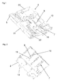
- FIG. 1 shows a first view of a module housing 2.
- the module housing 2 is shown without a cover, whereby inside the Module housing 2 two slides 7 can be seen, which are mounted displaceably on guide elements 16.
- a flexible circuit substrate 22 At the front end wall 5 of the module housing 2 is located on a flexible circuit substrate 22, on which a plurality of capacitive sensor elements 21 can be seen.
- the sensor elements 21 are used for spatially resolving detection of touches of the control surface of a control panel, not shown here.
- a slide 7 as an item is in the FIG. 4 displayed.
- the slider 7 is made in one piece from plastic or metal and has a base body 17 which is within the in the FIG. 1 shown module housing 2 is held by the guide elements 16. With the main body 17, the actuating surface 13 is connected via an angled portion. On the opposite side of the main body 17, a detent spring 9 is formed, which has a latching hook 10 and a run-on slope 15 at its front portion.
- the run-on slope 15 can at the same time form an electrical contact element 12, which, for example, can produce a ground connection, which is continued via a formed on the slide 7 contact spring 18, for example, to a circuit board, not shown in the drawing.
- a view of the underside of the module housing 2 shows the FIG. 2 , Recognizable are the detent springs 9 of the two slides 7, which each have an integrally formed latching hook 10.
- the detent springs 9 protrude in their unloaded basic position of slot-shaped recesses 19 on the underside of the module housing 2. Since the detent springs 9 are not guided on the module housing 2, they are against the main body 17 of the slider 7 a piece of elastic pivot.
- the module housing 2 with the detent springs 9 and the detent hook 10 formed thereon is from a different perspective in the FIG. 3 shown.
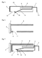
- FIGS. 5 to 10 The assembly of the in the FIGS. 1 to 3 shown module housing 2 to a previously not shown control panel is to be described below by the schematic representations of FIGS. 5 to 10 be clarified. Here are for similar or equivalent parts already in the FIGS. 1 to 4 have been used.
- a touch sensor with capacitive sensor elements, which is preferably part of the module housing 2 is for a better overview in the FIGS. 5 to 10 not shown.
- FIG. 5 greatly simplifies a module housing 2, whose representation is reduced to an outer housing body 20 and some fasteners.
- the latter includes a spring element 8, which is sketched here as a helical spring and in the FIG. 1 is shown as a leaf spring with similar function.
- the spring element 8 is on the one hand coupled to the housing body 20 of the module housing 2 and on the other hand acts on the slide 7. By a manually or mechanically exerted pressure on the actuating surface 13, the slide 7th are moved against the module housing 2, wherein at the same time the spring element 8 is tensioned.
- An at least mechanically coupled to the slide 7 or preferably integrally with the slide 7 executed detent spring 9 has an integrally formed latching hook 10, which projects in sections from a recess 19 of the module housing 2.
- the latching hook 10 forms here at the same time a run-on slope 15; in the more realistic representation of the FIG. 4 This run-up slope 15 is shown as a connected to the latching hook 10 item.
- the module housing 2 can be inserted accurately into a slide carrier 4, which in the FIG. 6 outlined with a control panel 1 is sketched.
- the control panel 1 consists in the simplest case of a thin compared to its surface area body whose front forms a substantially flat control surface 3.
- the control surface 3 can be realized for example by a part of the surface of the dashboard in a motor vehicle or by a part of the outer surface of a device housing.
- the end wall 5 of the module housing 2 has sensor elements and / or display elements, not shown here, which are to be attached as close as possible to the surface 6 on the back of the control panel 1 to ensure proper functioning and recognizability.
- touch sensors which function according to a capacitive operating principle, can be considerably impaired in their function even by small air gaps in the actuation path.
- a frame or shaft-like drawer carrier 4 is provided, which is simplified here by two parallel surfaces, between which the module housing. 2 is insertable.
- the module housing 2 has an undercut or a detent recess 11 into which a detent spring 10 integral with the slider 7 or mechanically coupled to the slider 7 can be inserted.
- FIG. 7 shows an assembly step in the assembly of module housing 2 and control panel 1.
- the module housing 2 is already here a bit far but not completely inserted into the drawer carrier 4.
- the protruding from the module housing 2 latching hook 10 runs with its run-on slope 15 against a housing edge of the insertion support 4 and is thereby pressed into the interior of the module housing 2.
- the latching hook 10 slides along the inner wall 14 of the insert carrier 4.
- the spring element 8 pushes the slider 7 back in the direction of its initial position, which the slider 7 but can not reach because the vertical portion of the latching hook 10 hooks on one edge of the recess 11 ( FIG. 10 ).
- the unlocking of the module housing 2 can, preferably with the aid of a retractable into the recess 11 tool, by a manual pushing out of the latching hook 10 from the recess 11 in the direction of the module housing 2 done.
Landscapes
- Engineering & Computer Science (AREA)
- Mechanical Engineering (AREA)
- Chemical & Material Sciences (AREA)
- Combustion & Propulsion (AREA)
- Transportation (AREA)
- Casings For Electric Apparatus (AREA)
Abstract
Description
- Die Erfindung betrifft ein Modulgehäuse mit mindestens einer aus dem Modulgehäuse ragenden Rastfeder, durch die das Modulgehäuse mit einem Einschubträger verriegelbar ist, und die zum Einschieben des Modulgehäuses in den Einschubträger und zum Entriegeln in das Modulgehäuse versenkbar ist. Die Erfindung betrifft zudem eine Bedienanordnung mit einem solchen Modulgehäuse.
- Ein solches Gehäuse ist aus der deutschen Patentschrift
DE 100 36 853 C2 bekannt. Das in diesem Dokument beschriebene Gehäuse ist insbesondere für ein Autoradio vorgesehen und der Einschubträger ist als Einbaurahmen oder Einbauschacht für das Autoradio beschrieben. Durch die Drehung eines Exzenters kann die Rastfeder in verschiedene Positionen bewegt werden, in der sie entweder zum Verriegeln des Gehäuses mit dem Einschubrahmen aus dem Gehäuse herausragt oder in der sie zum Entriegeln im Gehäuse versenkt ist. - Bedienanordnungen von elektrischen Geräten oder auch von Kraftfahrzeugen weisen oftmals Bedienblenden mit einer Vielzahl von Anzeige- und Schaltelementen auf. Moderne Bedienblenden besitzen häufig eine ebene Bedienfläche, bei denen Anzeige- und Schaltelemente auf der Rückseite montiert sind. Die Schaltelemente sind dabei vorzugsweise als kontaktlose Berührungssensoren ausgeführt.
- Bei der nachfolgend beschriebenen Bedienanordnung erfolgt eine Berührungserkennung über kapazitive Sensorelemente, die an der Außenseite eines Modulgehäuses angeordnet sind. Wichtig für die zuverlässige Funktion einer derartigen Sensorik ist die spaltfreie Ankopplung der Sensorelemente an die Rückseite der Bedienblende. Eine kapazitive Sensorik reagiert üblicherweise sehr empfindlich auf Abstandsänderungen zwischen den Sensorelementen und der Bedienblende. Hierbei sind besonders Luftstrecken aufgrund der im Vergleich zu Kunststoff sehr geringen relativen Permittivität von Luft nachteilig für eine störungsfreie Funktion der Sensoren.
- Es stellte sich die Aufgabe, eine Bedienanordnung zu schaffen, bei der ein Modulgehäuse auf kostengünstige und montagetechnisch einfache Weise spaltfrei an die Bedienblende anfügbar ist.
- Diese Aufgabe wird erfindungsgemäß dadurch gelöst, dass die Rastfeder an einen Schieber gekoppelt ist, der an dem Modulgehäuse gelagert ist und gegen die Kraft eines Federelements in der Einschubrichtung des Modulgehäuses verschiebbar ist.
- Das Verschieben des Schiebers erfolgt durch eine Druckeinwirkung nach dem Einsetzen des Modulgehäuses in einen Einschubträger, der einen Rahmen oder Schacht für das Modulgehäuse ausbildet. Der Einschubträger weist wenigstens eine Ausnehmung oder Hinterschneidung auf, in die ein mit der Rastfeder verbundene Rasthaken formschlüssig eingreifen kann.
- Durch die Bewegung des Schiebers wird ein Federelement gespannt, welches durch seine zwischen Modulgehäuse und Schieber wirkende Federkraft den Schieber in seine Ursprungsposition zurückzutreiben versucht. Dies ist aber wegen des mit dem Schieber verbundenen Rasthakens, der am Geräteträger eingehakt ist, nicht möglich, so dass umgekehrt eine Kraftwirkung auf das Modulgehäuse entsteht, die das Modulgehäuse gegen die Rückseite der Bedienblende drückt.
- Ein ausreichend stark dimensioniertes Federelement vorausgesetzt, wird so die der Bedienblende zugewandte Stirnfläche des Modulgehäuses dicht und spaltfrei an die Rückseite der Bedienblende angekoppelt. Zugleich werden dabei Fertigungstoleranzen des Modulgehäuses, des Einschubträgers und der der Federmechanik selbsttätig ausgeglichen.
- Die Kraft des Federelements auf den Rasthaken stellt vorteilhafterweise auch bei geometrieverändernden Einflüssen durch Klima, Fahrbetrieb oder Betätigung immer die Spaltfreiheit zwischen dem Modulgehäuse und der Bedienblende sicher.
- Das vorgeschlagene Modulgehäuse kann so mit einem vergleichsweise geringen Bauteile- und Montageaufwand spaltfrei an der Rückseite einer Bedienblende angeordnet werden.
- Wenn der mindestens eine Schieber metallisch ausgeführt ist, kann seine Geometrie so gestaltet sein, dass über den Schieber auch eine elektrische Verbindung von Komponenten der Modulelektronik zu Metallapplikationen der Bedienblende hergestellt werden kann. Dies ermöglicht beispielsweise störende Einflüsse derartiger Metallapplikationen durch eine Anbindung der Modulelektronik an ein Massepotential zu verringern.
- In Folgenden soll das Funktionsprinzip und ein Ausführungsbeispiel der Erfindung anhand der Zeichnung dargestellt und näher erläutert. Es zeigen
- Figuren 1 bis 3
- verschiedene Ansichten eines Modulgehäuses,
- Figur 4
- einen Schieber als Einzelteil,
- Figuren 5 bis 10
- schematische Ansichten eines Modulgehäuses und einer Bedienblende als Einzelteile und in verschiedenen Montagephasen.
- Die
Figur 1 zeigt eine erste Ansicht eines Modulgehäuses 2. Das Modulgehäuse 2 ist ohne eine Abdeckung dargestellt, wodurch im Inneren des Modulgehäuses 2 zwei Schieber 7 erkennbar sind, die an Führungselementen 16 verschieblich gelagert sind. - Über Durchbrüche an der Rückseite des Modulgehäuses 2 sind Endabschnitte der Schieber 7 zugänglich, welche Betätigungsflächen 13 ausbilden. Durch Krafteinwirkungen auf die Betätigungsflächen 13, beispielsweise durch manuelle Druckbetätigungen, können die an den Führungselementen 16 gelagerten Schieber 7 gegen den Gehäusekörper 20 des Modulgehäuses 2 verschoben werden, wodurch Federelemente 8, die hier einstückig als Blattfeder dargestellt sind, gespannt werden.
- An der vorderen Stirnwand 5 des Modulgehäuses 2 liegt ein flexibler Schaltungsträger 22 an, auf dem mehrere kapazitive Sensorelemente 21 erkennbar sind. Die Sensorelemente 21 dienen zur ortsauflösenden Erfassung von Berührungen der Bedienfläche einer hier nicht dargestellten Bedienblende. Um eine zuverlässige Funktion der Sensorik sicherzustellen, ist es erforderlich, die Stirnwand 5 des Modulgehäuses 2 mit den darauf befindlichen Sensorelementen 21 möglichst eng an die Rückseite der Bedienblende anzukoppeln.
- Ein Schieber 7 als Einzelteil ist in der
Figur 4 abgebildet. Der Schieber 7 ist einstückig aus Kunststoff oder Metall gefertigt und weist einen Grundkörper 17 auf, der innerhalb des in derFigur 1 dargestellten Modulgehäuses 2 von den Führungselementen 16 gehalten wird. Mit dem Grundkörper 17 ist über einen abgewinkelten Abschnitt die Betätigungsfläche 13 verbunden. Auf der entgegengesetzten Seite ist an den Grundkörper 17 eine Rastfeder 9 angeformt, welche an ihrem vorderen Abschnitt einen Rasthaken 10 und eine Anlaufschräge 15 aufweist. - Bei einem aus Metall bestehenden Schieber 7 kann die Anlaufschräge 15 zugleich ein elektrisches Kontaktelement 12 ausbilden, welches beispielsweise eine Masseverbindung herstellen kann, die über eine an den Schieber 7 angeformte Kontaktfeder 18 beispielsweise an einen in der Zeichnung nicht dargestellten Schaltungsträger weitergeführt wird.
- Eine Ansicht der Unterseite des Modulgehäuses 2 zeigt die
Figur 2 . Erkennbar sind die Rastfedern 9 der beiden Schieber 7, welche jeweils einen angeformten Rasthaken 10 aufweisen. Die Rastfedern 9 ragen in ihrer unbelasteten Grundstellung aus schlitzförmigen Ausnehmungen 19 an der Unterseite des Modulgehäuses 2 hervor. Da die Rastfedern 9 nicht am Modulgehäuse 2 geführt sind, sind sie gegen die Grundkörper 17 der Schieber 7 ein Stück weit elastisch verschwenkbar. Das Modulgehäuse 2 mit den Rastfedern 9 und den daran angeformten Rasthaken 10 ist aus einer anderen Perspektive in derFigur 3 dargestellt. - Die Montage des in den
Figuren 1 bis 3 abgebildeten Modulgehäuses 2 an eine bisher nicht dargestellte Bedienblende soll nachfolgend durch die schematischen Darstellungen derFiguren 5 bis 10 verdeutlicht werden. Dabei werden für gleichartige beziehungsweise gleichwirkende Teile die bereits in denFiguren 1 bis 4 verwendeten Bezugszeichen übernommen. Eine Berührungssensorik mit kapazitiven Sensorelementen, die vorzugsweise Bestandteil des Modulgehäuses 2 ist, ist zur besseren Übersicht in denFiguren 5 bis 10 nicht dargestellt. - Die
Figur 5 zeigt stark vereinfacht ein Modulgehäuse 2, dessen Darstellung auf einen äußeren Gehäusekörper 20 und einige Befestigungselemente reduziert ist. Zu letzteren gehört ein Federelement 8, welches hier als eine Schraubenfeder skizziert ist und das in derFigur 1 als eine Blattfeder mit gleichartiger Funktion dargestellt ist. Das Federelement 8 ist einerseits mit dem Gehäusekörper 20 des Modulgehäuses 2 gekoppelt und wirkt andererseits auf den Schieber 7. Durch eine manuell oder maschinell ausgeübte Druckeinwirkung auf die Betätigungsfläche 13 kann der Schieber 7 gegen das Modulgehäuse 2 verschoben werden, wobei zugleich das Federelement 8 gespannt wird. - Eine mit dem Schieber 7 zumindest mechanisch gekoppelte oder vorzugsweise einstückig mit dem Schieber 7 ausgeführte Rastfeder 9 weist einen angeformten Rasthaken 10 auf, der abschnittsweise aus einer Ausnehmung 19 des Modulgehäuses 2 herausragt. Der Rasthaken 10 bildet hier zugleich eine Anlaufschräge 15 aus; in der realitätsnäheren Darstellung der
Figur 4 ist diese Anlaufschräge 15 als ein mit dem Rasthaken 10 verbundenes Einzelteil dargestellt. - Das Modulgehäuse 2 kann passgenau in einen Einschubträger 4 eingefügt werden, der in der
Figur 6 mit einer Bedienblende 1 verbunden skizziert ist. Die Bedienblende 1 besteht im einfachsten Fall aus einem im Vergleich zu seiner Flächenausdehnung dünnen Körper, dessen Vorderseite eine im Wesentlichen ebene Bedienfläche 3 ausbildet. Die Bedienfläche 3 kann beispielsweise durch einen Teil der Oberfläche des Armaturenbretts in einem Kraftfahrzeug oder auch durch einen Teil der Außenfläche eines Gerätegehäuses realisiert sein. - Es sei angenommen, dass die Stirnwand 5 des Modulgehäuses 2 hier nicht dargestellte Sensorelemente und/oder Anzeigeelemente aufweist, welche zur Sicherstellung einer einwandfreien Funktion und Erkennbarkeit möglichst dicht an die Fläche 6 an der Rückseite der Bedienblende 1 angefügt werden sollen. Besonders Berührungssensoren, die nach einem kapazitiven Wirkprinzip funktionieren, können schon durch kleine Luftstrecken im Betätigungsweg erheblich in ihrer Funktion beeinträchtigt werden.
- Zur Befestigung des Modulgehäuses 2 an der Bedienblende 1 ist ein rahmen- oder schachtartiger Einschubträger 4 vorgesehen, der im hier vereinfacht durch zwei parallelen Flächen skizziert ist, zwischen die das Modulgehäuse 2 einschiebbar ist. Für jeden am Modulgehäuse 2 angeordneten Schieber 7 weist das Modulgehäuses 2 einen Hinterschnitt oder eine Rastausnehmung 11 auf, in den/die eine mit dem Schieber 7 einstückig ausgebildete oder mit dem Schieber 7 mechanisch gekoppelte Rastfeder 10 eingefügt werden kann.
- Die
Figur 7 zeigt einen Montageschritt beim Zusammenfügen von Modulgehäuse 2 und Bedienblende 1. Das Modulgehäuse 2 ist hier schon ein Stück weit aber noch nicht vollständig in den Einschubträger 4 eingeschoben. Während des Einfügevorgangs läuft der aus dem Modulgehäuse 2 hervorstehende Rasthaken 10 mit seiner Anlaufschräge 15 gegen eine Gehäusekante des Einschubträgers 4 und wird dadurch in das Innere des Modulgehäuses 2 gedrückt. Beim weiteren Einschieben gleitet der Rasthaken 10 an der Innenwand 14 des Einschubträgers 4 entlang. - Auch nachdem die Stirnwand 5 die Fläche 6 an der Rückseite der Bedienblende 1 erreicht hat, was in der
Figur 8 darstellt ist, liegt der Rasthaken 10 noch immer an der Innenwand 14 des Einschubträgers 4 an. Erst bei einer Verlagerung des Schiebers 7 durch eine Krafteinwirkung auf seine Betätigungsfläche 13 erreicht der Rasthaken 10 eine Stellung, in der der Rasthaken 10 durch die Federkraft der Rastfeder 9 in die Rastausnehmung 11 hineingedrückt wird (Figur 9 ). Durch die Lageveränderung des Schiebers 7 wird zugleich das Federelement 8 ein Stück weit gespannt. Nach dem Wegfall der Krafteinwirkung auf die Betätigungsfläche 13 schiebt das Federelement 8 den Schieber 7 zurück in die Richtung seiner Ausgangslage, welche der Schieber 7 aber nicht erreichen kann, da sich der senkrechte Abschnitt des Rasthakens 10 an einer Kante der Rastausnehmung 11 einhakt (Figur 10 ). - Die Federkraft des in dieser Position des Schiebers 7 noch teilweise gespannten Federelements 8 wirkt nun sowohl in Richtung auf den durch den Rasthaken 10 arretierten Schieber 7 als auch auf das Modulgehäuse 2, dessen Stirnwand 5 so durch das Federelement 8 an die Fläche 6 der Bedienblende 3 gepresst wird. Hierdurch ist eine kraftschlüssige enge Ankopplung des Modulgehäuses 2 an die Rückseite der Bedienblende 3 erreicht.
- Das Entriegeln des Modulgehäuses 2 kann, vorzugsweise unter Zuhilfenahme eines in die Rastausnehmung 11 einschiebbaren Werkzeugs, durch ein manuelles Herausdrücken des Rasthakens 10 aus der Rastausnehmung 11 in Richtung auf das Modulgehäuse 2 erfolgen.
-
- 1
- Bedienblende
- 2
- Modulgehäuse
- 3
- Bedienfläche
- 4
- Einschubträger
- 5
- Stirnwand
- 6
- Fläche
- 7
- Schieber
- 8
- Federelement
- 9
- Rastfeder
- 10
- Rasthaken
- 11
- Rastausnehmung
- 12
- Kontaktelement
- 13
- Betätigungsflächen
- 14
- Innenwand
- 15
- Anlaufschräge
- 16
- Führungselemente
- 17
- Grundkörper
- 18
- Kontaktfeder (Kontaktelement)
- 19
- Ausnehmungen
- 20
- Gehäusekörper
- 21
- Sensorelemente
- 22
- Schaltungsträger
Claims (12)
- Modulgehäuse mit mindestens einer aus dem Modulgehäuse (2) ragenden Rastfeder (9),
durch die das Modulgehäuse (2) mit einem Einschubträger (4) verriegelbar ist, und
die zum Einschieben des Modulgehäuses (2) in den Einschubträger (4) und zum Entriegeln in das Modulgehäuse (2) versenkbar ist,
dadurch gekennzeichnet,
dass die Rastfeder (9) an einen Schieber (7) gekoppelt ist, der an dem Modulgehäuse (2) gelagert ist und gegen die Kraft eines Federelements (8) in der Einschubrichtung des Modulgehäuses (2) verschiebbar ist. - Modulgehäuse nach Anspruch 1, dadurch gekennzeichnet, dass die Rastfeder (9) und der Schieber (7) einstückig miteinander ausgebildet sind.
- Modulgehäuse nach Anspruch 1, dadurch gekennzeichnet, dass der Schieber (7) aus Kunststoff ausgebildet ist
- Modulgehäuse nach Anspruch 1, dadurch gekennzeichnet, dass der Schieber (7) aus Metall ausgebildet ist.
- Modulgehäuse nach Anspruch 4, dadurch gekennzeichnet, dass der Schieber (7) einstückig mindestens ein elektrisches Kontaktelement (12, 18) ausbildet, dass mit elektrischen Komponenten im Inneren des Modulgehäuses (2) elektrisch verbunden ist.
- Modulgehäuse nach Anspruch 5, dadurch gekennzeichnet, dass das elektrische Kontaktelement (12, 18) federnd ausgebildet ist.
- Modulgehäuse nach Anspruch 1, dadurch gekennzeichnet, dass der Schieber (7) und das Federelement (8) einstückig miteinander ausgebildet sind.
- Modulgehäuse nach Anspruch 1, dadurch gekennzeichnet, dass der Schieber (7) und das Federelement (8) nicht einstückig miteinander ausgebildet sind und dass das Federelement (8) als eine Zylinderfeder, Schraubenfeder oder Blattfeder ausgebildet ist.
- Modulgehäuse nach Anspruch 2, dadurch gekennzeichnet, dass im Bereich der Stirnwand (5) des Modulgehäuses (2) mindestens ein kapazitives Sensorelement (21) angeordnet ist.
- Bedienanordnung, mit einem Modulgehäuse (2) nach Anspruch 1 und mit einem Einschubträger (4), dadurch gekennzeichnet, dass der Einschubträger (4) auf einer Seite mit einer Bedienblende (1) verbunden ist, die auf ihrer Vorderseite eine Bedienfläche (3) ausbildet, und dass nach dem vollständigen Einschieben des Modulgehäuses (2) in den Einschubträger (4) eine Stirnwand (5) des Modulgehäuses (2) an einer Fläche (6) an der Rückseite der Bedienblende (1) anliegt.
- Bedienanordnung nach Anspruch 10, dadurch gekennzeichnet, dass die Rastfeder (9) einen Rasthaken (10) aufweist, der durch eine Verschiebung des Schiebers (7) in eine Position bewegbar ist, in der die Rastfeder (9) den Rasthaken (10) in eine Rastausnehmung (11) oder Hinterschneidung des Einschubträgers (4) hineindrückt.
- Bedienanordnung nach Anspruch 11, dadurch gekennzeichnet, dass der Rasthaken (10) eine Anlaufschräge (15) aufweist, die beim Einschieben des Modulgehäuses (2) in den Einschubträger (4) auf den Einschubträger (4) trifft und dadurch den Rasthaken (10) gegen die Kraft der Rastfeder (9) verschiebt.
Applications Claiming Priority (1)
| Application Number | Priority Date | Filing Date | Title |
|---|---|---|---|
| DE102014007237.1A DE102014007237A1 (de) | 2014-05-16 | 2014-05-16 | Modulgehäuse und Bedienanordnung mit einem Modulgehäuse |
Publications (2)
| Publication Number | Publication Date |
|---|---|
| EP2944518A1 true EP2944518A1 (de) | 2015-11-18 |
| EP2944518B1 EP2944518B1 (de) | 2017-06-14 |
Family
ID=53177183
Family Applications (1)
| Application Number | Title | Priority Date | Filing Date |
|---|---|---|---|
| EP15167329.0A Active EP2944518B1 (de) | 2014-05-16 | 2015-05-12 | Modulgehäuse und bedienanordnung mit einem modulgehäuse |
Country Status (3)
| Country | Link |
|---|---|
| EP (1) | EP2944518B1 (de) |
| DE (1) | DE102014007237A1 (de) |
| ES (1) | ES2655270T3 (de) |
Citations (4)
| Publication number | Priority date | Publication date | Assignee | Title |
|---|---|---|---|---|
| US5366186A (en) * | 1993-08-19 | 1994-11-22 | Ford Motor Company | Module retention spring clip |
| DE19614781A1 (de) * | 1996-04-04 | 1997-10-09 | Becker Gmbh | Befestigungssystem für Autoradios |
| DE10036853C2 (de) | 2000-07-28 | 2002-10-10 | Harman Becker Automotive Sys | Gehäuse mit einer Befestigungsvorrichtung mit mindestens einer aus dem Gehäuse ragenden Rastfeder |
| US6760228B1 (en) * | 2003-02-25 | 2004-07-06 | International Business Machines Corporation | Apparatus for securing a removable circuit card in a computing system |
-
2014
- 2014-05-16 DE DE102014007237.1A patent/DE102014007237A1/de not_active Withdrawn
-
2015
- 2015-05-12 ES ES15167329.0T patent/ES2655270T3/es active Active
- 2015-05-12 EP EP15167329.0A patent/EP2944518B1/de active Active
Patent Citations (4)
| Publication number | Priority date | Publication date | Assignee | Title |
|---|---|---|---|---|
| US5366186A (en) * | 1993-08-19 | 1994-11-22 | Ford Motor Company | Module retention spring clip |
| DE19614781A1 (de) * | 1996-04-04 | 1997-10-09 | Becker Gmbh | Befestigungssystem für Autoradios |
| DE10036853C2 (de) | 2000-07-28 | 2002-10-10 | Harman Becker Automotive Sys | Gehäuse mit einer Befestigungsvorrichtung mit mindestens einer aus dem Gehäuse ragenden Rastfeder |
| US6760228B1 (en) * | 2003-02-25 | 2004-07-06 | International Business Machines Corporation | Apparatus for securing a removable circuit card in a computing system |
Also Published As
| Publication number | Publication date |
|---|---|
| DE102014007237A1 (de) | 2015-11-19 |
| ES2655270T3 (es) | 2018-02-19 |
| EP2944518B1 (de) | 2017-06-14 |
Similar Documents
| Publication | Publication Date | Title |
|---|---|---|
| EP3574393B1 (de) | Bedienvorrichtung für ein kraftfahrzeug | |
| DE102012016541B4 (de) | Geschirrspüler | |
| DE102019206282B4 (de) | Türentriegelungs- und/oder Türöffnungsmechanismus mit einer Betätigungsvorrichtung | |
| DE102006035837A1 (de) | Bedienelement | |
| DE102013110866A1 (de) | Kapazitive Sensoranordnung eines Kraftfahrzeugs | |
| DE102013006415B4 (de) | Vorrichtung zur Bedienung mehrerer Funktionen in einem Kraftfahrzeug | |
| DE202006006189U1 (de) | Antriebseinrichtung für bewegbare Möbelteile | |
| EP2944518B1 (de) | Modulgehäuse und bedienanordnung mit einem modulgehäuse | |
| EP3485500B1 (de) | Schaltbedienelement | |
| DE102010048515A1 (de) | Bedienmodul für ein Kraftfahrzeug | |
| DE102007042765A1 (de) | Bedienelement mit einem nach einem Kopfaufschlag reversiblen Bedienkopf für ein Fahrzeug | |
| DE102013020336A1 (de) | Bedieneinrichtung für ein Kraftfahrzeug, insbesondere zum Bedienen eines Schiebedachs, und Kraftfahrzeug mit einer solchen Bedieneinrichtung | |
| DE202010006900U1 (de) | Betätigungsvorrichtung für eine Feststellbremse | |
| EP2975588B1 (de) | Fernsteuerung | |
| DE102014208025A1 (de) | Vorrichtung zur Einstellung eines Betriebsparameters einer elektrischen Einrichtung | |
| DE102010005309A1 (de) | Verkleidungsteil mit mindestens einem Befestigungsmittel zur Befestigung an einer Fahrzeugkarosserie | |
| EP3563724B1 (de) | Vorrichtung zum schliessen eines bewegbaren möbelteils | |
| DE102018214688B4 (de) | Drucktaster | |
| EP2050359B1 (de) | Möbelgriff | |
| DE102011088800B4 (de) | Bedienelement, insbesondere für ein Kraftfahrzeug | |
| DE19959101A1 (de) | Bewegliche Blende für Führungsschienen eines Kraftfahrzeugsitzes | |
| DE102016202158A1 (de) | Fahrzeugsitzeinrichtung für ein Fahrzeug | |
| DE202013104627U1 (de) | Einrichtung zum Öffnen und Schließen eines Fachs | |
| DE102010020903B4 (de) | Bedieneinheit für ein Fahrzeug | |
| DE102016107858A1 (de) | Heckblendenanordnung eines Kraftfahrzeugs |
Legal Events
| Date | Code | Title | Description |
|---|---|---|---|
| PUAI | Public reference made under article 153(3) epc to a published international application that has entered the european phase |
Free format text: ORIGINAL CODE: 0009012 |
|
| AK | Designated contracting states |
Kind code of ref document: A1 Designated state(s): AL AT BE BG CH CY CZ DE DK EE ES FI FR GB GR HR HU IE IS IT LI LT LU LV MC MK MT NL NO PL PT RO RS SE SI SK SM TR |
|
| AX | Request for extension of the european patent |
Extension state: BA ME |
|
| 17P | Request for examination filed |
Effective date: 20160114 |
|
| RBV | Designated contracting states (corrected) |
Designated state(s): AL AT BE BG CH CY CZ DE DK EE ES FI FR GB GR HR HU IE IS IT LI LT LU LV MC MK MT NL NO PL PT RO RS SE SI SK SM TR |
|
| GRAP | Despatch of communication of intention to grant a patent |
Free format text: ORIGINAL CODE: EPIDOSNIGR1 |
|
| INTG | Intention to grant announced |
Effective date: 20170223 |
|
| RIN1 | Information on inventor provided before grant (corrected) |
Inventor name: MIEDL, FLORIAN Inventor name: BLECKMANN, MICHAEL Inventor name: KAMINSKI, DEAN Inventor name: TILLE, THOMAS |
|
| GRAS | Grant fee paid |
Free format text: ORIGINAL CODE: EPIDOSNIGR3 |
|
| GRAA | (expected) grant |
Free format text: ORIGINAL CODE: 0009210 |
|
| AK | Designated contracting states |
Kind code of ref document: B1 Designated state(s): AL AT BE BG CH CY CZ DE DK EE ES FI FR GB GR HR HU IE IS IT LI LT LU LV MC MK MT NL NO PL PT RO RS SE SI SK SM TR |
|
| REG | Reference to a national code |
Ref country code: GB Ref legal event code: FG4D Free format text: NOT ENGLISH |
|
| REG | Reference to a national code |
Ref country code: CH Ref legal event code: EP Ref country code: AT Ref legal event code: REF Ref document number: 900629 Country of ref document: AT Kind code of ref document: T Effective date: 20170615 |
|
| REG | Reference to a national code |
Ref country code: IE Ref legal event code: FG4D Free format text: LANGUAGE OF EP DOCUMENT: GERMAN |
|
| REG | Reference to a national code |
Ref country code: DE Ref legal event code: R096 Ref document number: 502015001208 Country of ref document: DE |
|
| REG | Reference to a national code |
Ref country code: SE Ref legal event code: TRGR |
|
| REG | Reference to a national code |
Ref country code: NL Ref legal event code: MP Effective date: 20170614 |
|
| REG | Reference to a national code |
Ref country code: LT Ref legal event code: MG4D |
|
| PG25 | Lapsed in a contracting state [announced via postgrant information from national office to epo] |
Ref country code: LT Free format text: LAPSE BECAUSE OF FAILURE TO SUBMIT A TRANSLATION OF THE DESCRIPTION OR TO PAY THE FEE WITHIN THE PRESCRIBED TIME-LIMIT Effective date: 20170614 Ref country code: HR Free format text: LAPSE BECAUSE OF FAILURE TO SUBMIT A TRANSLATION OF THE DESCRIPTION OR TO PAY THE FEE WITHIN THE PRESCRIBED TIME-LIMIT Effective date: 20170614 Ref country code: GR Free format text: LAPSE BECAUSE OF FAILURE TO SUBMIT A TRANSLATION OF THE DESCRIPTION OR TO PAY THE FEE WITHIN THE PRESCRIBED TIME-LIMIT Effective date: 20170915 Ref country code: FI Free format text: LAPSE BECAUSE OF FAILURE TO SUBMIT A TRANSLATION OF THE DESCRIPTION OR TO PAY THE FEE WITHIN THE PRESCRIBED TIME-LIMIT Effective date: 20170614 Ref country code: NO Free format text: LAPSE BECAUSE OF FAILURE TO SUBMIT A TRANSLATION OF THE DESCRIPTION OR TO PAY THE FEE WITHIN THE PRESCRIBED TIME-LIMIT Effective date: 20170914 |
|
| PG25 | Lapsed in a contracting state [announced via postgrant information from national office to epo] |
Ref country code: BG Free format text: LAPSE BECAUSE OF FAILURE TO SUBMIT A TRANSLATION OF THE DESCRIPTION OR TO PAY THE FEE WITHIN THE PRESCRIBED TIME-LIMIT Effective date: 20170914 Ref country code: NL Free format text: LAPSE BECAUSE OF FAILURE TO SUBMIT A TRANSLATION OF THE DESCRIPTION OR TO PAY THE FEE WITHIN THE PRESCRIBED TIME-LIMIT Effective date: 20170614 Ref country code: LV Free format text: LAPSE BECAUSE OF FAILURE TO SUBMIT A TRANSLATION OF THE DESCRIPTION OR TO PAY THE FEE WITHIN THE PRESCRIBED TIME-LIMIT Effective date: 20170614 Ref country code: RS Free format text: LAPSE BECAUSE OF FAILURE TO SUBMIT A TRANSLATION OF THE DESCRIPTION OR TO PAY THE FEE WITHIN THE PRESCRIBED TIME-LIMIT Effective date: 20170614 |
|
| PG25 | Lapsed in a contracting state [announced via postgrant information from national office to epo] |
Ref country code: EE Free format text: LAPSE BECAUSE OF FAILURE TO SUBMIT A TRANSLATION OF THE DESCRIPTION OR TO PAY THE FEE WITHIN THE PRESCRIBED TIME-LIMIT Effective date: 20170614 Ref country code: RO Free format text: LAPSE BECAUSE OF FAILURE TO SUBMIT A TRANSLATION OF THE DESCRIPTION OR TO PAY THE FEE WITHIN THE PRESCRIBED TIME-LIMIT Effective date: 20170614 Ref country code: SK Free format text: LAPSE BECAUSE OF FAILURE TO SUBMIT A TRANSLATION OF THE DESCRIPTION OR TO PAY THE FEE WITHIN THE PRESCRIBED TIME-LIMIT Effective date: 20170614 |
|
| REG | Reference to a national code |
Ref country code: ES Ref legal event code: FG2A Ref document number: 2655270 Country of ref document: ES Kind code of ref document: T3 Effective date: 20180219 |
|
| PG25 | Lapsed in a contracting state [announced via postgrant information from national office to epo] |
Ref country code: PL Free format text: LAPSE BECAUSE OF FAILURE TO SUBMIT A TRANSLATION OF THE DESCRIPTION OR TO PAY THE FEE WITHIN THE PRESCRIBED TIME-LIMIT Effective date: 20170614 Ref country code: SM Free format text: LAPSE BECAUSE OF FAILURE TO SUBMIT A TRANSLATION OF THE DESCRIPTION OR TO PAY THE FEE WITHIN THE PRESCRIBED TIME-LIMIT Effective date: 20170614 Ref country code: IS Free format text: LAPSE BECAUSE OF FAILURE TO SUBMIT A TRANSLATION OF THE DESCRIPTION OR TO PAY THE FEE WITHIN THE PRESCRIBED TIME-LIMIT Effective date: 20171014 |
|
| RAP2 | Party data changed (patent owner data changed or rights of a patent transferred) |
Owner name: LEOPOLD KOSTAL GMBH & CO. KG |
|
| REG | Reference to a national code |
Ref country code: DE Ref legal event code: R097 Ref document number: 502015001208 Country of ref document: DE |
|
| PLBE | No opposition filed within time limit |
Free format text: ORIGINAL CODE: 0009261 |
|
| STAA | Information on the status of an ep patent application or granted ep patent |
Free format text: STATUS: NO OPPOSITION FILED WITHIN TIME LIMIT |
|
| PG25 | Lapsed in a contracting state [announced via postgrant information from national office to epo] |
Ref country code: DK Free format text: LAPSE BECAUSE OF FAILURE TO SUBMIT A TRANSLATION OF THE DESCRIPTION OR TO PAY THE FEE WITHIN THE PRESCRIBED TIME-LIMIT Effective date: 20170614 |
|
| REG | Reference to a national code |
Ref country code: FR Ref legal event code: PLFP Year of fee payment: 4 |
|
| 26N | No opposition filed |
Effective date: 20180315 |
|
| PG25 | Lapsed in a contracting state [announced via postgrant information from national office to epo] |
Ref country code: SI Free format text: LAPSE BECAUSE OF FAILURE TO SUBMIT A TRANSLATION OF THE DESCRIPTION OR TO PAY THE FEE WITHIN THE PRESCRIBED TIME-LIMIT Effective date: 20170614 |
|
| PG25 | Lapsed in a contracting state [announced via postgrant information from national office to epo] |
Ref country code: MT Free format text: LAPSE BECAUSE OF FAILURE TO SUBMIT A TRANSLATION OF THE DESCRIPTION OR TO PAY THE FEE WITHIN THE PRESCRIBED TIME-LIMIT Effective date: 20170614 |
|
| REG | Reference to a national code |
Ref country code: CH Ref legal event code: PL |
|
| REG | Reference to a national code |
Ref country code: BE Ref legal event code: MM Effective date: 20180531 |
|
| PG25 | Lapsed in a contracting state [announced via postgrant information from national office to epo] |
Ref country code: MC Free format text: LAPSE BECAUSE OF FAILURE TO SUBMIT A TRANSLATION OF THE DESCRIPTION OR TO PAY THE FEE WITHIN THE PRESCRIBED TIME-LIMIT Effective date: 20170614 |
|
| REG | Reference to a national code |
Ref country code: IE Ref legal event code: MM4A |
|
| PG25 | Lapsed in a contracting state [announced via postgrant information from national office to epo] |
Ref country code: LI Free format text: LAPSE BECAUSE OF NON-PAYMENT OF DUE FEES Effective date: 20180531 Ref country code: CH Free format text: LAPSE BECAUSE OF NON-PAYMENT OF DUE FEES Effective date: 20180531 |
|
| PG25 | Lapsed in a contracting state [announced via postgrant information from national office to epo] |
Ref country code: LU Free format text: LAPSE BECAUSE OF NON-PAYMENT OF DUE FEES Effective date: 20180512 |
|
| PG25 | Lapsed in a contracting state [announced via postgrant information from national office to epo] |
Ref country code: IE Free format text: LAPSE BECAUSE OF NON-PAYMENT OF DUE FEES Effective date: 20180512 |
|
| PG25 | Lapsed in a contracting state [announced via postgrant information from national office to epo] |
Ref country code: BE Free format text: LAPSE BECAUSE OF NON-PAYMENT OF DUE FEES Effective date: 20180531 |
|
| PG25 | Lapsed in a contracting state [announced via postgrant information from national office to epo] |
Ref country code: TR Free format text: LAPSE BECAUSE OF FAILURE TO SUBMIT A TRANSLATION OF THE DESCRIPTION OR TO PAY THE FEE WITHIN THE PRESCRIBED TIME-LIMIT Effective date: 20170614 |
|
| PG25 | Lapsed in a contracting state [announced via postgrant information from national office to epo] |
Ref country code: PT Free format text: LAPSE BECAUSE OF FAILURE TO SUBMIT A TRANSLATION OF THE DESCRIPTION OR TO PAY THE FEE WITHIN THE PRESCRIBED TIME-LIMIT Effective date: 20170614 |
|
| PG25 | Lapsed in a contracting state [announced via postgrant information from national office to epo] |
Ref country code: MK Free format text: LAPSE BECAUSE OF NON-PAYMENT OF DUE FEES Effective date: 20170614 Ref country code: CY Free format text: LAPSE BECAUSE OF FAILURE TO SUBMIT A TRANSLATION OF THE DESCRIPTION OR TO PAY THE FEE WITHIN THE PRESCRIBED TIME-LIMIT Effective date: 20170614 Ref country code: HU Free format text: LAPSE BECAUSE OF FAILURE TO SUBMIT A TRANSLATION OF THE DESCRIPTION OR TO PAY THE FEE WITHIN THE PRESCRIBED TIME-LIMIT; INVALID AB INITIO Effective date: 20150512 |
|
| REG | Reference to a national code |
Ref country code: DE Ref legal event code: R081 Ref document number: 502015001208 Country of ref document: DE Owner name: BAYERISCHE MOTOREN WERKE AKTIENGESELLSCHAFT, DE Free format text: FORMER OWNERS: LEOPOLD KOSTAL GMBH & CO. KG, 58513 LUEDENSCHEID, DE; BAYERISCHE MOTOREN WERKE AKTIENGESELLSCHAFT, 80809 MUENCHEN, DE Ref country code: DE Ref legal event code: R081 Ref document number: 502015001208 Country of ref document: DE Owner name: KOSTAL AUTOMOBIL ELEKTRIK GMBH & CO. KG, DE Free format text: FORMER OWNERS: LEOPOLD KOSTAL GMBH & CO. KG, 58513 LUEDENSCHEID, DE; BAYERISCHE MOTOREN WERKE AKTIENGESELLSCHAFT, 80809 MUENCHEN, DE |
|
| PG25 | Lapsed in a contracting state [announced via postgrant information from national office to epo] |
Ref country code: AL Free format text: LAPSE BECAUSE OF FAILURE TO SUBMIT A TRANSLATION OF THE DESCRIPTION OR TO PAY THE FEE WITHIN THE PRESCRIBED TIME-LIMIT Effective date: 20170614 |
|
| REG | Reference to a national code |
Ref country code: AT Ref legal event code: MM01 Ref document number: 900629 Country of ref document: AT Kind code of ref document: T Effective date: 20200512 |
|
| PG25 | Lapsed in a contracting state [announced via postgrant information from national office to epo] |
Ref country code: AT Free format text: LAPSE BECAUSE OF NON-PAYMENT OF DUE FEES Effective date: 20200512 |
|
| P01 | Opt-out of the competence of the unified patent court (upc) registered |
Effective date: 20231108 |
|
| PGFP | Annual fee paid to national office [announced via postgrant information from national office to epo] |
Ref country code: DE Payment date: 20250415 Year of fee payment: 11 |
|
| PGFP | Annual fee paid to national office [announced via postgrant information from national office to epo] |
Ref country code: GB Payment date: 20250508 Year of fee payment: 11 Ref country code: ES Payment date: 20250603 Year of fee payment: 11 |
|
| PGFP | Annual fee paid to national office [announced via postgrant information from national office to epo] |
Ref country code: IT Payment date: 20250424 Year of fee payment: 11 |
|
| PGFP | Annual fee paid to national office [announced via postgrant information from national office to epo] |
Ref country code: FR Payment date: 20250530 Year of fee payment: 11 |
|
| PGFP | Annual fee paid to national office [announced via postgrant information from national office to epo] |
Ref country code: CZ Payment date: 20250401 Year of fee payment: 11 |
|
| PGFP | Annual fee paid to national office [announced via postgrant information from national office to epo] |
Ref country code: SE Payment date: 20250513 Year of fee payment: 11 |