EP2944518A1 - Module housing and operating assembly with a module housing - Google Patents
Module housing and operating assembly with a module housing Download PDFInfo
- Publication number
- EP2944518A1 EP2944518A1 EP15167329.0A EP15167329A EP2944518A1 EP 2944518 A1 EP2944518 A1 EP 2944518A1 EP 15167329 A EP15167329 A EP 15167329A EP 2944518 A1 EP2944518 A1 EP 2944518A1
- Authority
- EP
- European Patent Office
- Prior art keywords
- module housing
- slide
- spring
- latching hook
- control panel
- Prior art date
- Legal status (The legal status is an assumption and is not a legal conclusion. Google has not performed a legal analysis and makes no representation as to the accuracy of the status listed.)
- Granted
Links
- 238000003780 insertion Methods 0.000 claims abstract description 12
- 230000037431 insertion Effects 0.000 claims abstract description 12
- 239000002184 metal Substances 0.000 claims description 5
- 238000006073 displacement reaction Methods 0.000 claims description 2
- 230000008878 coupling Effects 0.000 description 2
- 238000010168 coupling process Methods 0.000 description 2
- 238000005859 coupling reaction Methods 0.000 description 2
- 238000001514 detection method Methods 0.000 description 2
- 230000009471 action Effects 0.000 description 1
- 230000008859 change Effects 0.000 description 1
- 230000000694 effects Effects 0.000 description 1
- 230000008030 elimination Effects 0.000 description 1
- 238000003379 elimination reaction Methods 0.000 description 1
- 230000001771 impaired effect Effects 0.000 description 1
- 230000002452 interceptive effect Effects 0.000 description 1
- 238000004519 manufacturing process Methods 0.000 description 1
- 230000007246 mechanism Effects 0.000 description 1
- 238000000034 method Methods 0.000 description 1
- 230000008569 process Effects 0.000 description 1
- 239000000758 substrate Substances 0.000 description 1
Images


Classifications
-
- B60K35/10—
-
- B—PERFORMING OPERATIONS; TRANSPORTING
- B60—VEHICLES IN GENERAL
- B60R—VEHICLES, VEHICLE FITTINGS, OR VEHICLE PARTS, NOT OTHERWISE PROVIDED FOR
- B60R11/00—Arrangements for holding or mounting articles, not otherwise provided for
- B60R11/02—Arrangements for holding or mounting articles, not otherwise provided for for radio sets, television sets, telephones, or the like; Arrangement of controls thereof
- B60R11/0205—Arrangements for holding or mounting articles, not otherwise provided for for radio sets, television sets, telephones, or the like; Arrangement of controls thereof for radio sets
-
- B60K35/50—
-
- B60K2360/143—
-
- B60K2360/828—
-
- B—PERFORMING OPERATIONS; TRANSPORTING
- B60—VEHICLES IN GENERAL
- B60R—VEHICLES, VEHICLE FITTINGS, OR VEHICLE PARTS, NOT OTHERWISE PROVIDED FOR
- B60R11/00—Arrangements for holding or mounting articles, not otherwise provided for
- B60R2011/0042—Arrangements for holding or mounting articles, not otherwise provided for characterised by mounting means
- B60R2011/0043—Arrangements for holding or mounting articles, not otherwise provided for characterised by mounting means for integrated articles, i.e. not substantially protruding from the surrounding parts
- B60R2011/0045—Arrangements for holding or mounting articles, not otherwise provided for characterised by mounting means for integrated articles, i.e. not substantially protruding from the surrounding parts with visible part, e.g. flush mounted
- B60R2011/0047—Arrangements for holding or mounting articles, not otherwise provided for characterised by mounting means for integrated articles, i.e. not substantially protruding from the surrounding parts with visible part, e.g. flush mounted using hidden fastening means
Abstract
Beschrieben wird ein Modulgehäuse (2) mit mindestens einer aus dem Modulgehäuse (2) ragenden Rastfeder (9), durch die das Modulgehäuse (2) mit einem Einschubträger (4) verriegelbar ist, und die zum Einschieben des Modulgehäuses (2) in den Einschubträger (4) und zum Entriegeln in das Modulgehäuse (2) versenkbar ist, wobei die Rastfeder (9) an einen Schieber (7) gekoppelt ist, der an dem Modulgehäuse (2) gelagert ist und gegen die Kraft eines Federelements (8) in der Einschubrichtung des Modulgehäuses (2) verschiebbar ist. Beschrieben wird zudem eine Bedienanordnung mit einem solchen Modulgehäuse (2).Described is a module housing (2) with at least one of the module housing (2) protruding detent spring (9) through which the module housing (2) with a slide-in support (4) can be locked, and for inserting the module housing (2) in the drawer carrier (4) and for unlocking in the module housing (2) is retractable, wherein the detent spring (9) is coupled to a slide (7) which is mounted on the module housing (2) and against the force of a spring element (8) in the Insertion direction of the module housing (2) is displaceable. Also described is an operating arrangement with such a module housing (2).
Description
Die Erfindung betrifft ein Modulgehäuse mit mindestens einer aus dem Modulgehäuse ragenden Rastfeder, durch die das Modulgehäuse mit einem Einschubträger verriegelbar ist, und die zum Einschieben des Modulgehäuses in den Einschubträger und zum Entriegeln in das Modulgehäuse versenkbar ist. Die Erfindung betrifft zudem eine Bedienanordnung mit einem solchen Modulgehäuse.The invention relates to a module housing with at least one projecting from the module housing detent spring, through which the module housing can be locked with a slide-in carrier, and which is retractable for insertion of the module housing in the drawer carrier and for unlocking in the module housing. The invention also relates to an operating arrangement with such a module housing.
Ein solches Gehäuse ist aus der deutschen Patentschrift
Bedienanordnungen von elektrischen Geräten oder auch von Kraftfahrzeugen weisen oftmals Bedienblenden mit einer Vielzahl von Anzeige- und Schaltelementen auf. Moderne Bedienblenden besitzen häufig eine ebene Bedienfläche, bei denen Anzeige- und Schaltelemente auf der Rückseite montiert sind. Die Schaltelemente sind dabei vorzugsweise als kontaktlose Berührungssensoren ausgeführt.Operating arrangements of electrical devices or motor vehicles often have control panels with a variety of display and switching elements. Modern control panels often have a flat control surface, in which display and switching elements are mounted on the back. The switching elements are preferably designed as contactless contact sensors.
Bei der nachfolgend beschriebenen Bedienanordnung erfolgt eine Berührungserkennung über kapazitive Sensorelemente, die an der Außenseite eines Modulgehäuses angeordnet sind. Wichtig für die zuverlässige Funktion einer derartigen Sensorik ist die spaltfreie Ankopplung der Sensorelemente an die Rückseite der Bedienblende. Eine kapazitive Sensorik reagiert üblicherweise sehr empfindlich auf Abstandsänderungen zwischen den Sensorelementen und der Bedienblende. Hierbei sind besonders Luftstrecken aufgrund der im Vergleich zu Kunststoff sehr geringen relativen Permittivität von Luft nachteilig für eine störungsfreie Funktion der Sensoren.In the operating arrangement described below, a touch detection via capacitive sensor elements, which are arranged on the outside of a module housing. Important for the reliable function of such a sensor is the gap-free coupling of the sensor elements the back of the control panel. A capacitive sensor typically reacts very sensitive to changes in distance between the sensor elements and the control panel. In this case, especially air gaps are disadvantageous due to the very low compared to plastic relative permittivity of air for trouble-free operation of the sensors.
Es stellte sich die Aufgabe, eine Bedienanordnung zu schaffen, bei der ein Modulgehäuse auf kostengünstige und montagetechnisch einfache Weise spaltfrei an die Bedienblende anfügbar ist.It has set itself the task of creating an operating arrangement in which a module housing can be attached to the control panel in a cost-effective and simple manner from a simple assembly point.
Diese Aufgabe wird erfindungsgemäß dadurch gelöst, dass die Rastfeder an einen Schieber gekoppelt ist, der an dem Modulgehäuse gelagert ist und gegen die Kraft eines Federelements in der Einschubrichtung des Modulgehäuses verschiebbar ist.This object is achieved in that the detent spring is coupled to a slider which is mounted on the module housing and against the force of a spring element in the insertion direction of the module housing is displaceable.
Das Verschieben des Schiebers erfolgt durch eine Druckeinwirkung nach dem Einsetzen des Modulgehäuses in einen Einschubträger, der einen Rahmen oder Schacht für das Modulgehäuse ausbildet. Der Einschubträger weist wenigstens eine Ausnehmung oder Hinterschneidung auf, in die ein mit der Rastfeder verbundene Rasthaken formschlüssig eingreifen kann.The sliding of the slider is effected by a pressure action after inserting the module housing in a slide-in carrier, which forms a frame or slot for the module housing. The drawer carrier has at least one recess or undercut into which a locking hook connected to the detent spring can engage positively.
Durch die Bewegung des Schiebers wird ein Federelement gespannt, welches durch seine zwischen Modulgehäuse und Schieber wirkende Federkraft den Schieber in seine Ursprungsposition zurückzutreiben versucht. Dies ist aber wegen des mit dem Schieber verbundenen Rasthakens, der am Geräteträger eingehakt ist, nicht möglich, so dass umgekehrt eine Kraftwirkung auf das Modulgehäuse entsteht, die das Modulgehäuse gegen die Rückseite der Bedienblende drückt.By the movement of the slide, a spring element is tensioned, which tries to drive back the slide to its original position by acting between the module housing and slide spring force. However, this is not possible because of the slide hook connected to the latching hook, which is hooked to the device carrier, so that conversely a force acting on the module housing is created, which presses the module housing against the back of the control panel.
Ein ausreichend stark dimensioniertes Federelement vorausgesetzt, wird so die der Bedienblende zugewandte Stirnfläche des Modulgehäuses dicht und spaltfrei an die Rückseite der Bedienblende angekoppelt. Zugleich werden dabei Fertigungstoleranzen des Modulgehäuses, des Einschubträgers und der der Federmechanik selbsttätig ausgeglichen.Provided that the spring element is sufficiently dimensioned, the face of the module housing facing the control panel will be tight and sealed gap-free coupled to the back of the control panel. At the same time manufacturing tolerances of the module housing, the insert carrier and the spring mechanism are automatically compensated.
Die Kraft des Federelements auf den Rasthaken stellt vorteilhafterweise auch bei geometrieverändernden Einflüssen durch Klima, Fahrbetrieb oder Betätigung immer die Spaltfreiheit zwischen dem Modulgehäuse und der Bedienblende sicher.The force of the spring element on the latching hook is advantageously also in geometrieverändernden influences by climate, driving or operation always the gap between the module housing and the control panel safely.
Das vorgeschlagene Modulgehäuse kann so mit einem vergleichsweise geringen Bauteile- und Montageaufwand spaltfrei an der Rückseite einer Bedienblende angeordnet werden.The proposed module housing can be arranged with a comparatively low component and assembly costs gap-free at the back of a control panel.
Wenn der mindestens eine Schieber metallisch ausgeführt ist, kann seine Geometrie so gestaltet sein, dass über den Schieber auch eine elektrische Verbindung von Komponenten der Modulelektronik zu Metallapplikationen der Bedienblende hergestellt werden kann. Dies ermöglicht beispielsweise störende Einflüsse derartiger Metallapplikationen durch eine Anbindung der Modulelektronik an ein Massepotential zu verringern.If the at least one slide is made metallic, its geometry can be designed such that an electrical connection of components of the module electronics to metal applications of the control panel can be produced via the slide. This makes it possible, for example, to reduce interfering influences of such metal applications by connecting the module electronics to a ground potential.
In Folgenden soll das Funktionsprinzip und ein Ausführungsbeispiel der Erfindung anhand der Zeichnung dargestellt und näher erläutert. Es zeigen
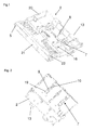
Figuren 1 bis 3- verschiedene Ansichten eines Modulgehäuses,
Figur 4- einen Schieber als Einzelteil,
Figuren 5 bis 10- schematische Ansichten eines Modulgehäuses und einer Bedienblende als Einzelteile und in verschiedenen Montagephasen.
- FIGS. 1 to 3
- different views of a module housing,
- FIG. 4
- a slider as an individual part,
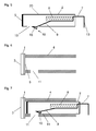
- FIGS. 5 to 10
- schematic views of a module housing and a control panel as individual parts and in different assembly phases.
Die
Über Durchbrüche an der Rückseite des Modulgehäuses 2 sind Endabschnitte der Schieber 7 zugänglich, welche Betätigungsflächen 13 ausbilden. Durch Krafteinwirkungen auf die Betätigungsflächen 13, beispielsweise durch manuelle Druckbetätigungen, können die an den Führungselementen 16 gelagerten Schieber 7 gegen den Gehäusekörper 20 des Modulgehäuses 2 verschoben werden, wodurch Federelemente 8, die hier einstückig als Blattfeder dargestellt sind, gespannt werden.Through openings at the back of the
An der vorderen Stirnwand 5 des Modulgehäuses 2 liegt ein flexibler Schaltungsträger 22 an, auf dem mehrere kapazitive Sensorelemente 21 erkennbar sind. Die Sensorelemente 21 dienen zur ortsauflösenden Erfassung von Berührungen der Bedienfläche einer hier nicht dargestellten Bedienblende. Um eine zuverlässige Funktion der Sensorik sicherzustellen, ist es erforderlich, die Stirnwand 5 des Modulgehäuses 2 mit den darauf befindlichen Sensorelementen 21 möglichst eng an die Rückseite der Bedienblende anzukoppeln.At the
Ein Schieber 7 als Einzelteil ist in der
Bei einem aus Metall bestehenden Schieber 7 kann die Anlaufschräge 15 zugleich ein elektrisches Kontaktelement 12 ausbilden, welches beispielsweise eine Masseverbindung herstellen kann, die über eine an den Schieber 7 angeformte Kontaktfeder 18 beispielsweise an einen in der Zeichnung nicht dargestellten Schaltungsträger weitergeführt wird.In the case of a
Eine Ansicht der Unterseite des Modulgehäuses 2 zeigt die
Die Montage des in den
Die
Eine mit dem Schieber 7 zumindest mechanisch gekoppelte oder vorzugsweise einstückig mit dem Schieber 7 ausgeführte Rastfeder 9 weist einen angeformten Rasthaken 10 auf, der abschnittsweise aus einer Ausnehmung 19 des Modulgehäuses 2 herausragt. Der Rasthaken 10 bildet hier zugleich eine Anlaufschräge 15 aus; in der realitätsnäheren Darstellung der
Das Modulgehäuse 2 kann passgenau in einen Einschubträger 4 eingefügt werden, der in der
Es sei angenommen, dass die Stirnwand 5 des Modulgehäuses 2 hier nicht dargestellte Sensorelemente und/oder Anzeigeelemente aufweist, welche zur Sicherstellung einer einwandfreien Funktion und Erkennbarkeit möglichst dicht an die Fläche 6 an der Rückseite der Bedienblende 1 angefügt werden sollen. Besonders Berührungssensoren, die nach einem kapazitiven Wirkprinzip funktionieren, können schon durch kleine Luftstrecken im Betätigungsweg erheblich in ihrer Funktion beeinträchtigt werden.It is assumed that the
Zur Befestigung des Modulgehäuses 2 an der Bedienblende 1 ist ein rahmen- oder schachtartiger Einschubträger 4 vorgesehen, der im hier vereinfacht durch zwei parallelen Flächen skizziert ist, zwischen die das Modulgehäuse 2 einschiebbar ist. Für jeden am Modulgehäuse 2 angeordneten Schieber 7 weist das Modulgehäuses 2 einen Hinterschnitt oder eine Rastausnehmung 11 auf, in den/die eine mit dem Schieber 7 einstückig ausgebildete oder mit dem Schieber 7 mechanisch gekoppelte Rastfeder 10 eingefügt werden kann.For attachment of the
Die
Auch nachdem die Stirnwand 5 die Fläche 6 an der Rückseite der Bedienblende 1 erreicht hat, was in der
Die Federkraft des in dieser Position des Schiebers 7 noch teilweise gespannten Federelements 8 wirkt nun sowohl in Richtung auf den durch den Rasthaken 10 arretierten Schieber 7 als auch auf das Modulgehäuse 2, dessen Stirnwand 5 so durch das Federelement 8 an die Fläche 6 der Bedienblende 3 gepresst wird. Hierdurch ist eine kraftschlüssige enge Ankopplung des Modulgehäuses 2 an die Rückseite der Bedienblende 3 erreicht.The spring force of the
Das Entriegeln des Modulgehäuses 2 kann, vorzugsweise unter Zuhilfenahme eines in die Rastausnehmung 11 einschiebbaren Werkzeugs, durch ein manuelles Herausdrücken des Rasthakens 10 aus der Rastausnehmung 11 in Richtung auf das Modulgehäuse 2 erfolgen.The unlocking of the
- 11
- Bedienblendecontrol panel
- 22
- Modulgehäusemodule housing
- 33
- Bedienflächeoperating surface
- 44
- Einschubträgershelf supports
- 55
- Stirnwandbulkhead
- 66
- Flächearea
- 77
- Schieberpusher
- 88th
- Federelementspring element
- 99
- Rastfederdetent spring
- 1010
- Rasthakenlatch hook
- 1111
- Rastausnehmungrecess
- 1212
- Kontaktelementcontact element
- 1313
- Betätigungsflächenoperating surfaces
- 1414
- Innenwandinner wall
- 1515
- Anlaufschrägestarting slope
- 1616
- Führungselementeguide elements
- 1717
- Grundkörperbody
- 1818
- Kontaktfeder (Kontaktelement)Contact spring (contact element)
- 1919
- Ausnehmungenrecesses
- 2020
- Gehäusekörperhousing body
- 2121
- Sensorelementesensor elements
- 2222
- Schaltungsträgercircuit support
Claims (12)
durch die das Modulgehäuse (2) mit einem Einschubträger (4) verriegelbar ist, und
die zum Einschieben des Modulgehäuses (2) in den Einschubträger (4) und zum Entriegeln in das Modulgehäuse (2) versenkbar ist,
dadurch gekennzeichnet,
dass die Rastfeder (9) an einen Schieber (7) gekoppelt ist, der an dem Modulgehäuse (2) gelagert ist und gegen die Kraft eines Federelements (8) in der Einschubrichtung des Modulgehäuses (2) verschiebbar ist.Module housing with at least one of the module housing (2) projecting detent spring (9),
by which the module housing (2) with a slide-in carrier (4) can be locked, and
which is retractable for insertion of the module housing (2) in the insertion carrier (4) and for unlocking in the module housing (2),
characterized,
that the locking spring (9) to a slide (7) is coupled, which is mounted to the module housing (2) and against the force of a spring element (8) in the direction of insertion of the module housing (2) is displaceable.
Applications Claiming Priority (1)
| Application Number | Priority Date | Filing Date | Title |
|---|---|---|---|
| DE102014007237.1A DE102014007237A1 (en) | 2014-05-16 | 2014-05-16 | Module housing and operating arrangement with a module housing |
Publications (2)
| Publication Number | Publication Date |
|---|---|
| EP2944518A1 true EP2944518A1 (en) | 2015-11-18 |
| EP2944518B1 EP2944518B1 (en) | 2017-06-14 |
Family
ID=53177183
Family Applications (1)
| Application Number | Title | Priority Date | Filing Date |
|---|---|---|---|
| EP15167329.0A Active EP2944518B1 (en) | 2014-05-16 | 2015-05-12 | Module housing and operating assembly with a module housing |
Country Status (3)
| Country | Link |
|---|---|
| EP (1) | EP2944518B1 (en) |
| DE (1) | DE102014007237A1 (en) |
| ES (1) | ES2655270T3 (en) |
Citations (4)
| Publication number | Priority date | Publication date | Assignee | Title |
|---|---|---|---|---|
| US5366186A (en) * | 1993-08-19 | 1994-11-22 | Ford Motor Company | Module retention spring clip |
| DE19614781A1 (en) * | 1996-04-04 | 1997-10-09 | Becker Gmbh | Fixture system for automobile radio esp. in dashboard |
| DE10036853C2 (en) | 2000-07-28 | 2002-10-10 | Harman Becker Automotive Sys | Housing with a fastening device with at least one detent spring protruding from the housing |
| US6760228B1 (en) * | 2003-02-25 | 2004-07-06 | International Business Machines Corporation | Apparatus for securing a removable circuit card in a computing system |
-
2014
- 2014-05-16 DE DE102014007237.1A patent/DE102014007237A1/en not_active Withdrawn
-
2015
- 2015-05-12 ES ES15167329.0T patent/ES2655270T3/en active Active
- 2015-05-12 EP EP15167329.0A patent/EP2944518B1/en active Active
Patent Citations (4)
| Publication number | Priority date | Publication date | Assignee | Title |
|---|---|---|---|---|
| US5366186A (en) * | 1993-08-19 | 1994-11-22 | Ford Motor Company | Module retention spring clip |
| DE19614781A1 (en) * | 1996-04-04 | 1997-10-09 | Becker Gmbh | Fixture system for automobile radio esp. in dashboard |
| DE10036853C2 (en) | 2000-07-28 | 2002-10-10 | Harman Becker Automotive Sys | Housing with a fastening device with at least one detent spring protruding from the housing |
| US6760228B1 (en) * | 2003-02-25 | 2004-07-06 | International Business Machines Corporation | Apparatus for securing a removable circuit card in a computing system |
Also Published As
| Publication number | Publication date |
|---|---|
| EP2944518B1 (en) | 2017-06-14 |
| DE102014007237A1 (en) | 2015-11-19 |
| ES2655270T3 (en) | 2018-02-19 |
Similar Documents
| Publication | Publication Date | Title |
|---|---|---|
| EP3574393B1 (en) | Operating device for a motor vehicle | |
| DE102011083524A1 (en) | Turn / push control device for a human-machine interface | |
| DE102012016541B4 (en) | dishwasher | |
| DE202006006189U1 (en) | Drive device for movable furniture parts | |
| DE102013110866A1 (en) | Capacitive sensor arrangement of a motor vehicle | |
| DE102019206282A1 (en) | Door unlocking and / or door opening mechanism with an actuating device | |
| DE102013006415B4 (en) | Device for operating several functions in a motor vehicle | |
| EP2944518B1 (en) | Module housing and operating assembly with a module housing | |
| DE102010048515A1 (en) | Control module for arrangement in e.g. center console of motor car, has rail-guided displacement device moving touch pad relative to rotary push button during transition from one use position to another use position | |
| DE102014208025B4 (en) | Device for setting an operating parameter of an electrical device | |
| DE102013020336A1 (en) | Operating device for a motor vehicle, in particular for operating a sunroof, and motor vehicle with such an operating device | |
| DE202010006900U1 (en) | Actuation device for a parking brake | |
| EP3563724B1 (en) | Device for closing a movable piece of furniture | |
| DE102010005309A1 (en) | Lining part i.e. interior lining part, for door of vehicle, has two brackets comprising two locking elements that are arranged one behind other in axial direction such that lining part is formed with tolerance in horizontal direction | |
| EP3485500B1 (en) | Shift operating element | |
| EP2050359B1 (en) | Furniture grip | |
| DE202013104627U1 (en) | Device for opening and closing a compartment | |
| EP2975588B1 (en) | Remote control | |
| DE19959101A1 (en) | Car seat guide rail cover is closed off by top rail when this overlaps floor rail using entrained synchronous movement of top rail and cover to keep floor rail closed when free. | |
| DE102005033124B4 (en) | Fastening device for a switch | |
| DE102016107858A1 (en) | Rear panel arrangement of a motor vehicle | |
| DE102016202158A1 (en) | Vehicle seat device for a vehicle | |
| DE102010020903B4 (en) | Operating unit for a vehicle | |
| WO2015140115A1 (en) | Electronic device and operating assembly having an electronic device | |
| DE102011085725A1 (en) | Operation unit for vehicle component e.g. heating apparatus, has stroke gear box that transmits load applied to one end of key for support of stroke movement of opposite end of key in same direction |
Legal Events
| Date | Code | Title | Description |
|---|---|---|---|
| PUAI | Public reference made under article 153(3) epc to a published international application that has entered the european phase |
Free format text: ORIGINAL CODE: 0009012 |
|
| AK | Designated contracting states |
Kind code of ref document: A1 Designated state(s): AL AT BE BG CH CY CZ DE DK EE ES FI FR GB GR HR HU IE IS IT LI LT LU LV MC MK MT NL NO PL PT RO RS SE SI SK SM TR |
|
| AX | Request for extension of the european patent |
Extension state: BA ME |
|
| 17P | Request for examination filed |
Effective date: 20160114 |
|
| RBV | Designated contracting states (corrected) |
Designated state(s): AL AT BE BG CH CY CZ DE DK EE ES FI FR GB GR HR HU IE IS IT LI LT LU LV MC MK MT NL NO PL PT RO RS SE SI SK SM TR |
|
| GRAP | Despatch of communication of intention to grant a patent |
Free format text: ORIGINAL CODE: EPIDOSNIGR1 |
|
| INTG | Intention to grant announced |
Effective date: 20170223 |
|
| RIN1 | Information on inventor provided before grant (corrected) |
Inventor name: MIEDL, FLORIAN Inventor name: BLECKMANN, MICHAEL Inventor name: KAMINSKI, DEAN Inventor name: TILLE, THOMAS |
|
| GRAS | Grant fee paid |
Free format text: ORIGINAL CODE: EPIDOSNIGR3 |
|
| GRAA | (expected) grant |
Free format text: ORIGINAL CODE: 0009210 |
|
| AK | Designated contracting states |
Kind code of ref document: B1 Designated state(s): AL AT BE BG CH CY CZ DE DK EE ES FI FR GB GR HR HU IE IS IT LI LT LU LV MC MK MT NL NO PL PT RO RS SE SI SK SM TR |
|
| REG | Reference to a national code |
Ref country code: GB Ref legal event code: FG4D Free format text: NOT ENGLISH |
|
| REG | Reference to a national code |
Ref country code: CH Ref legal event code: EP Ref country code: AT Ref legal event code: REF Ref document number: 900629 Country of ref document: AT Kind code of ref document: T Effective date: 20170615 |
|
| REG | Reference to a national code |
Ref country code: IE Ref legal event code: FG4D Free format text: LANGUAGE OF EP DOCUMENT: GERMAN |
|
| REG | Reference to a national code |
Ref country code: DE Ref legal event code: R096 Ref document number: 502015001208 Country of ref document: DE |
|
| REG | Reference to a national code |
Ref country code: SE Ref legal event code: TRGR |
|
| REG | Reference to a national code |
Ref country code: NL Ref legal event code: MP Effective date: 20170614 |
|
| REG | Reference to a national code |
Ref country code: LT Ref legal event code: MG4D |
|
| PG25 | Lapsed in a contracting state [announced via postgrant information from national office to epo] |
Ref country code: LT Free format text: LAPSE BECAUSE OF FAILURE TO SUBMIT A TRANSLATION OF THE DESCRIPTION OR TO PAY THE FEE WITHIN THE PRESCRIBED TIME-LIMIT Effective date: 20170614 Ref country code: HR Free format text: LAPSE BECAUSE OF FAILURE TO SUBMIT A TRANSLATION OF THE DESCRIPTION OR TO PAY THE FEE WITHIN THE PRESCRIBED TIME-LIMIT Effective date: 20170614 Ref country code: GR Free format text: LAPSE BECAUSE OF FAILURE TO SUBMIT A TRANSLATION OF THE DESCRIPTION OR TO PAY THE FEE WITHIN THE PRESCRIBED TIME-LIMIT Effective date: 20170915 Ref country code: FI Free format text: LAPSE BECAUSE OF FAILURE TO SUBMIT A TRANSLATION OF THE DESCRIPTION OR TO PAY THE FEE WITHIN THE PRESCRIBED TIME-LIMIT Effective date: 20170614 Ref country code: NO Free format text: LAPSE BECAUSE OF FAILURE TO SUBMIT A TRANSLATION OF THE DESCRIPTION OR TO PAY THE FEE WITHIN THE PRESCRIBED TIME-LIMIT Effective date: 20170914 |
|
| PG25 | Lapsed in a contracting state [announced via postgrant information from national office to epo] |
Ref country code: BG Free format text: LAPSE BECAUSE OF FAILURE TO SUBMIT A TRANSLATION OF THE DESCRIPTION OR TO PAY THE FEE WITHIN THE PRESCRIBED TIME-LIMIT Effective date: 20170914 Ref country code: NL Free format text: LAPSE BECAUSE OF FAILURE TO SUBMIT A TRANSLATION OF THE DESCRIPTION OR TO PAY THE FEE WITHIN THE PRESCRIBED TIME-LIMIT Effective date: 20170614 Ref country code: LV Free format text: LAPSE BECAUSE OF FAILURE TO SUBMIT A TRANSLATION OF THE DESCRIPTION OR TO PAY THE FEE WITHIN THE PRESCRIBED TIME-LIMIT Effective date: 20170614 Ref country code: RS Free format text: LAPSE BECAUSE OF FAILURE TO SUBMIT A TRANSLATION OF THE DESCRIPTION OR TO PAY THE FEE WITHIN THE PRESCRIBED TIME-LIMIT Effective date: 20170614 |
|
| PG25 | Lapsed in a contracting state [announced via postgrant information from national office to epo] |
Ref country code: EE Free format text: LAPSE BECAUSE OF FAILURE TO SUBMIT A TRANSLATION OF THE DESCRIPTION OR TO PAY THE FEE WITHIN THE PRESCRIBED TIME-LIMIT Effective date: 20170614 Ref country code: RO Free format text: LAPSE BECAUSE OF FAILURE TO SUBMIT A TRANSLATION OF THE DESCRIPTION OR TO PAY THE FEE WITHIN THE PRESCRIBED TIME-LIMIT Effective date: 20170614 Ref country code: SK Free format text: LAPSE BECAUSE OF FAILURE TO SUBMIT A TRANSLATION OF THE DESCRIPTION OR TO PAY THE FEE WITHIN THE PRESCRIBED TIME-LIMIT Effective date: 20170614 |
|
| REG | Reference to a national code |
Ref country code: ES Ref legal event code: FG2A Ref document number: 2655270 Country of ref document: ES Kind code of ref document: T3 Effective date: 20180219 |
|
| PG25 | Lapsed in a contracting state [announced via postgrant information from national office to epo] |
Ref country code: PL Free format text: LAPSE BECAUSE OF FAILURE TO SUBMIT A TRANSLATION OF THE DESCRIPTION OR TO PAY THE FEE WITHIN THE PRESCRIBED TIME-LIMIT Effective date: 20170614 Ref country code: SM Free format text: LAPSE BECAUSE OF FAILURE TO SUBMIT A TRANSLATION OF THE DESCRIPTION OR TO PAY THE FEE WITHIN THE PRESCRIBED TIME-LIMIT Effective date: 20170614 Ref country code: IS Free format text: LAPSE BECAUSE OF FAILURE TO SUBMIT A TRANSLATION OF THE DESCRIPTION OR TO PAY THE FEE WITHIN THE PRESCRIBED TIME-LIMIT Effective date: 20171014 |
|
| RAP2 | Party data changed (patent owner data changed or rights of a patent transferred) |
Owner name: LEOPOLD KOSTAL GMBH & CO. KG |
|
| REG | Reference to a national code |
Ref country code: DE Ref legal event code: R097 Ref document number: 502015001208 Country of ref document: DE |
|
| PLBE | No opposition filed within time limit |
Free format text: ORIGINAL CODE: 0009261 |
|
| STAA | Information on the status of an ep patent application or granted ep patent |
Free format text: STATUS: NO OPPOSITION FILED WITHIN TIME LIMIT |
|
| PG25 | Lapsed in a contracting state [announced via postgrant information from national office to epo] |
Ref country code: DK Free format text: LAPSE BECAUSE OF FAILURE TO SUBMIT A TRANSLATION OF THE DESCRIPTION OR TO PAY THE FEE WITHIN THE PRESCRIBED TIME-LIMIT Effective date: 20170614 |
|
| REG | Reference to a national code |
Ref country code: FR Ref legal event code: PLFP Year of fee payment: 4 |
|
| 26N | No opposition filed |
Effective date: 20180315 |
|
| PG25 | Lapsed in a contracting state [announced via postgrant information from national office to epo] |
Ref country code: SI Free format text: LAPSE BECAUSE OF FAILURE TO SUBMIT A TRANSLATION OF THE DESCRIPTION OR TO PAY THE FEE WITHIN THE PRESCRIBED TIME-LIMIT Effective date: 20170614 |
|
| PG25 | Lapsed in a contracting state [announced via postgrant information from national office to epo] |
Ref country code: MT Free format text: LAPSE BECAUSE OF FAILURE TO SUBMIT A TRANSLATION OF THE DESCRIPTION OR TO PAY THE FEE WITHIN THE PRESCRIBED TIME-LIMIT Effective date: 20170614 |
|
| REG | Reference to a national code |
Ref country code: CH Ref legal event code: PL |
|
| REG | Reference to a national code |
Ref country code: BE Ref legal event code: MM Effective date: 20180531 |
|
| PG25 | Lapsed in a contracting state [announced via postgrant information from national office to epo] |
Ref country code: MC Free format text: LAPSE BECAUSE OF FAILURE TO SUBMIT A TRANSLATION OF THE DESCRIPTION OR TO PAY THE FEE WITHIN THE PRESCRIBED TIME-LIMIT Effective date: 20170614 |
|
| REG | Reference to a national code |
Ref country code: IE Ref legal event code: MM4A |
|
| PG25 | Lapsed in a contracting state [announced via postgrant information from national office to epo] |
Ref country code: LI Free format text: LAPSE BECAUSE OF NON-PAYMENT OF DUE FEES Effective date: 20180531 Ref country code: CH Free format text: LAPSE BECAUSE OF NON-PAYMENT OF DUE FEES Effective date: 20180531 |
|
| PG25 | Lapsed in a contracting state [announced via postgrant information from national office to epo] |
Ref country code: LU Free format text: LAPSE BECAUSE OF NON-PAYMENT OF DUE FEES Effective date: 20180512 |
|
| PG25 | Lapsed in a contracting state [announced via postgrant information from national office to epo] |
Ref country code: IE Free format text: LAPSE BECAUSE OF NON-PAYMENT OF DUE FEES Effective date: 20180512 |
|
| PG25 | Lapsed in a contracting state [announced via postgrant information from national office to epo] |
Ref country code: BE Free format text: LAPSE BECAUSE OF NON-PAYMENT OF DUE FEES Effective date: 20180531 |
|
| PG25 | Lapsed in a contracting state [announced via postgrant information from national office to epo] |
Ref country code: TR Free format text: LAPSE BECAUSE OF FAILURE TO SUBMIT A TRANSLATION OF THE DESCRIPTION OR TO PAY THE FEE WITHIN THE PRESCRIBED TIME-LIMIT Effective date: 20170614 |
|
| PG25 | Lapsed in a contracting state [announced via postgrant information from national office to epo] |
Ref country code: PT Free format text: LAPSE BECAUSE OF FAILURE TO SUBMIT A TRANSLATION OF THE DESCRIPTION OR TO PAY THE FEE WITHIN THE PRESCRIBED TIME-LIMIT Effective date: 20170614 |
|
| PG25 | Lapsed in a contracting state [announced via postgrant information from national office to epo] |
Ref country code: MK Free format text: LAPSE BECAUSE OF NON-PAYMENT OF DUE FEES Effective date: 20170614 Ref country code: CY Free format text: LAPSE BECAUSE OF FAILURE TO SUBMIT A TRANSLATION OF THE DESCRIPTION OR TO PAY THE FEE WITHIN THE PRESCRIBED TIME-LIMIT Effective date: 20170614 Ref country code: HU Free format text: LAPSE BECAUSE OF FAILURE TO SUBMIT A TRANSLATION OF THE DESCRIPTION OR TO PAY THE FEE WITHIN THE PRESCRIBED TIME-LIMIT; INVALID AB INITIO Effective date: 20150512 |
|
| REG | Reference to a national code |
Ref country code: DE Ref legal event code: R081 Ref document number: 502015001208 Country of ref document: DE Owner name: BAYERISCHE MOTOREN WERKE AKTIENGESELLSCHAFT, DE Free format text: FORMER OWNERS: LEOPOLD KOSTAL GMBH & CO. KG, 58513 LUEDENSCHEID, DE; BAYERISCHE MOTOREN WERKE AKTIENGESELLSCHAFT, 80809 MUENCHEN, DE Ref country code: DE Ref legal event code: R081 Ref document number: 502015001208 Country of ref document: DE Owner name: KOSTAL AUTOMOBIL ELEKTRIK GMBH & CO. KG, DE Free format text: FORMER OWNERS: LEOPOLD KOSTAL GMBH & CO. KG, 58513 LUEDENSCHEID, DE; BAYERISCHE MOTOREN WERKE AKTIENGESELLSCHAFT, 80809 MUENCHEN, DE |
|
| PG25 | Lapsed in a contracting state [announced via postgrant information from national office to epo] |
Ref country code: AL Free format text: LAPSE BECAUSE OF FAILURE TO SUBMIT A TRANSLATION OF THE DESCRIPTION OR TO PAY THE FEE WITHIN THE PRESCRIBED TIME-LIMIT Effective date: 20170614 |
|
| REG | Reference to a national code |
Ref country code: AT Ref legal event code: MM01 Ref document number: 900629 Country of ref document: AT Kind code of ref document: T Effective date: 20200512 |
|
| PG25 | Lapsed in a contracting state [announced via postgrant information from national office to epo] |
Ref country code: AT Free format text: LAPSE BECAUSE OF NON-PAYMENT OF DUE FEES Effective date: 20200512 |
|
| PGFP | Annual fee paid to national office [announced via postgrant information from national office to epo] |
Ref country code: SE Payment date: 20230303 Year of fee payment: 9 |
|
| PGFP | Annual fee paid to national office [announced via postgrant information from national office to epo] |
Ref country code: IT Payment date: 20230511 Year of fee payment: 9 Ref country code: FR Payment date: 20230531 Year of fee payment: 9 Ref country code: ES Payment date: 20230607 Year of fee payment: 9 Ref country code: DE Payment date: 20230530 Year of fee payment: 9 Ref country code: CZ Payment date: 20230421 Year of fee payment: 9 |
|
| PGFP | Annual fee paid to national office [announced via postgrant information from national office to epo] |
Ref country code: GB Payment date: 20230505 Year of fee payment: 9 |
|
| P01 | Opt-out of the competence of the unified patent court (upc) registered |
Effective date: 20231108 |