EP2942503B1 - Exhaust gas purification system and ozone generator - Google Patents
Exhaust gas purification system and ozone generator Download PDFInfo
- Publication number
- EP2942503B1 EP2942503B1 EP14746671.8A EP14746671A EP2942503B1 EP 2942503 B1 EP2942503 B1 EP 2942503B1 EP 14746671 A EP14746671 A EP 14746671A EP 2942503 B1 EP2942503 B1 EP 2942503B1
- Authority
- EP
- European Patent Office
- Prior art keywords
- ozone
- warm air
- vortex tube
- oxygen
- enriched gas
- Prior art date
- Legal status (The legal status is an assumption and is not a legal conclusion. Google has not performed a legal analysis and makes no representation as to the accuracy of the status listed.)
- Not-in-force
Links
Images


Classifications
-
- B—PERFORMING OPERATIONS; TRANSPORTING
- B01—PHYSICAL OR CHEMICAL PROCESSES OR APPARATUS IN GENERAL
- B01D—SEPARATION
- B01D53/00—Separation of gases or vapours; Recovering vapours of volatile solvents from gases; Chemical or biological purification of waste gases, e.g. engine exhaust gases, smoke, fumes, flue gases, aerosols
- B01D53/34—Chemical or biological purification of waste gases
- B01D53/92—Chemical or biological purification of waste gases of engine exhaust gases
- B01D53/94—Chemical or biological purification of waste gases of engine exhaust gases by catalytic processes
- B01D53/9404—Removing only nitrogen compounds
- B01D53/9409—Nitrogen oxides
- B01D53/9431—Processes characterised by a specific device
-
- C—CHEMISTRY; METALLURGY
- C01—INORGANIC CHEMISTRY
- C01B—NON-METALLIC ELEMENTS; COMPOUNDS THEREOF; METALLOIDS OR COMPOUNDS THEREOF NOT COVERED BY SUBCLASS C01C
- C01B13/00—Oxygen; Ozone; Oxides or hydroxides in general
- C01B13/10—Preparation of ozone
-
- C—CHEMISTRY; METALLURGY
- C01—INORGANIC CHEMISTRY
- C01B—NON-METALLIC ELEMENTS; COMPOUNDS THEREOF; METALLOIDS OR COMPOUNDS THEREOF NOT COVERED BY SUBCLASS C01C
- C01B13/00—Oxygen; Ozone; Oxides or hydroxides in general
- C01B13/10—Preparation of ozone
- C01B13/11—Preparation of ozone by electric discharge
-
- C—CHEMISTRY; METALLURGY
- C25—ELECTROLYTIC OR ELECTROPHORETIC PROCESSES; APPARATUS THEREFOR
- C25B—ELECTROLYTIC OR ELECTROPHORETIC PROCESSES FOR THE PRODUCTION OF COMPOUNDS OR NON-METALS; APPARATUS THEREFOR
- C25B1/00—Electrolytic production of inorganic compounds or non-metals
- C25B1/01—Products
- C25B1/13—Ozone
-
- F—MECHANICAL ENGINEERING; LIGHTING; HEATING; WEAPONS; BLASTING
- F01—MACHINES OR ENGINES IN GENERAL; ENGINE PLANTS IN GENERAL; STEAM ENGINES
- F01N—GAS-FLOW SILENCERS OR EXHAUST APPARATUS FOR MACHINES OR ENGINES IN GENERAL; GAS-FLOW SILENCERS OR EXHAUST APPARATUS FOR INTERNAL-COMBUSTION ENGINES
- F01N3/00—Exhaust or silencing apparatus having means for purifying, rendering innocuous, or otherwise treating exhaust
- F01N3/08—Exhaust or silencing apparatus having means for purifying, rendering innocuous, or otherwise treating exhaust for rendering innocuous
- F01N3/10—Exhaust or silencing apparatus having means for purifying, rendering innocuous, or otherwise treating exhaust for rendering innocuous by thermal or catalytic conversion of noxious components of exhaust
- F01N3/18—Exhaust or silencing apparatus having means for purifying, rendering innocuous, or otherwise treating exhaust for rendering innocuous by thermal or catalytic conversion of noxious components of exhaust characterised by methods of operation; Control
- F01N3/20—Exhaust or silencing apparatus having means for purifying, rendering innocuous, or otherwise treating exhaust for rendering innocuous by thermal or catalytic conversion of noxious components of exhaust characterised by methods of operation; Control specially adapted for catalytic conversion
- F01N3/206—Adding periodically or continuously substances to exhaust gases for promoting purification, e.g. catalytic material in liquid form, NOx reducing agents
- F01N3/2066—Selective catalytic reduction [SCR]
-
- B—PERFORMING OPERATIONS; TRANSPORTING
- B01—PHYSICAL OR CHEMICAL PROCESSES OR APPARATUS IN GENERAL
- B01D—SEPARATION
- B01D2251/00—Reactants
- B01D2251/10—Oxidants
- B01D2251/104—Ozone
-
- B—PERFORMING OPERATIONS; TRANSPORTING
- B01—PHYSICAL OR CHEMICAL PROCESSES OR APPARATUS IN GENERAL
- B01D—SEPARATION
- B01D2256/00—Main component in the product gas stream after treatment
- B01D2256/10—Nitrogen
-
- B—PERFORMING OPERATIONS; TRANSPORTING
- B01—PHYSICAL OR CHEMICAL PROCESSES OR APPARATUS IN GENERAL
- B01D—SEPARATION
- B01D2256/00—Main component in the product gas stream after treatment
- B01D2256/12—Oxygen
-
- B—PERFORMING OPERATIONS; TRANSPORTING
- B01—PHYSICAL OR CHEMICAL PROCESSES OR APPARATUS IN GENERAL
- B01D—SEPARATION
- B01D53/00—Separation of gases or vapours; Recovering vapours of volatile solvents from gases; Chemical or biological purification of waste gases, e.g. engine exhaust gases, smoke, fumes, flue gases, aerosols
- B01D53/22—Separation of gases or vapours; Recovering vapours of volatile solvents from gases; Chemical or biological purification of waste gases, e.g. engine exhaust gases, smoke, fumes, flue gases, aerosols by diffusion
-
- B—PERFORMING OPERATIONS; TRANSPORTING
- B01—PHYSICAL OR CHEMICAL PROCESSES OR APPARATUS IN GENERAL
- B01D—SEPARATION
- B01D53/00—Separation of gases or vapours; Recovering vapours of volatile solvents from gases; Chemical or biological purification of waste gases, e.g. engine exhaust gases, smoke, fumes, flue gases, aerosols
- B01D53/26—Drying gases or vapours
- B01D53/261—Drying gases or vapours by adsorption
-
- C—CHEMISTRY; METALLURGY
- C01—INORGANIC CHEMISTRY
- C01B—NON-METALLIC ELEMENTS; COMPOUNDS THEREOF; METALLOIDS OR COMPOUNDS THEREOF NOT COVERED BY SUBCLASS C01C
- C01B2201/00—Preparation of ozone by electrical discharge
- C01B2201/60—Feed streams for electrical dischargers
- C01B2201/64—Oxygen
-
- F—MECHANICAL ENGINEERING; LIGHTING; HEATING; WEAPONS; BLASTING
- F01—MACHINES OR ENGINES IN GENERAL; ENGINE PLANTS IN GENERAL; STEAM ENGINES
- F01N—GAS-FLOW SILENCERS OR EXHAUST APPARATUS FOR MACHINES OR ENGINES IN GENERAL; GAS-FLOW SILENCERS OR EXHAUST APPARATUS FOR INTERNAL-COMBUSTION ENGINES
- F01N2240/00—Combination or association of two or more different exhaust treating devices, or of at least one such device with an auxiliary device, not covered by indexing codes F01N2230/00 or F01N2250/00, one of the devices being
- F01N2240/38—Combination or association of two or more different exhaust treating devices, or of at least one such device with an auxiliary device, not covered by indexing codes F01N2230/00 or F01N2250/00, one of the devices being an ozone (O3) generator, e.g. for adding ozone after generation of ozone from air
-
- F—MECHANICAL ENGINEERING; LIGHTING; HEATING; WEAPONS; BLASTING
- F01—MACHINES OR ENGINES IN GENERAL; ENGINE PLANTS IN GENERAL; STEAM ENGINES
- F01N—GAS-FLOW SILENCERS OR EXHAUST APPARATUS FOR MACHINES OR ENGINES IN GENERAL; GAS-FLOW SILENCERS OR EXHAUST APPARATUS FOR INTERNAL-COMBUSTION ENGINES
- F01N2610/00—Adding substances to exhaust gases
- F01N2610/02—Adding substances to exhaust gases the substance being ammonia or urea
-
- F—MECHANICAL ENGINEERING; LIGHTING; HEATING; WEAPONS; BLASTING
- F01—MACHINES OR ENGINES IN GENERAL; ENGINE PLANTS IN GENERAL; STEAM ENGINES
- F01N—GAS-FLOW SILENCERS OR EXHAUST APPARATUS FOR MACHINES OR ENGINES IN GENERAL; GAS-FLOW SILENCERS OR EXHAUST APPARATUS FOR INTERNAL-COMBUSTION ENGINES
- F01N2610/00—Adding substances to exhaust gases
- F01N2610/06—Adding substances to exhaust gases the substance being in the gaseous form
-
- F—MECHANICAL ENGINEERING; LIGHTING; HEATING; WEAPONS; BLASTING
- F01—MACHINES OR ENGINES IN GENERAL; ENGINE PLANTS IN GENERAL; STEAM ENGINES
- F01N—GAS-FLOW SILENCERS OR EXHAUST APPARATUS FOR MACHINES OR ENGINES IN GENERAL; GAS-FLOW SILENCERS OR EXHAUST APPARATUS FOR INTERNAL-COMBUSTION ENGINES
- F01N2610/00—Adding substances to exhaust gases
- F01N2610/08—Adding substances to exhaust gases with prior mixing of the substances with a gas, e.g. air
-
- F—MECHANICAL ENGINEERING; LIGHTING; HEATING; WEAPONS; BLASTING
- F01—MACHINES OR ENGINES IN GENERAL; ENGINE PLANTS IN GENERAL; STEAM ENGINES
- F01N—GAS-FLOW SILENCERS OR EXHAUST APPARATUS FOR MACHINES OR ENGINES IN GENERAL; GAS-FLOW SILENCERS OR EXHAUST APPARATUS FOR INTERNAL-COMBUSTION ENGINES
- F01N2610/00—Adding substances to exhaust gases
- F01N2610/11—Adding substances to exhaust gases the substance or part of the dosing system being cooled
-
- Y—GENERAL TAGGING OF NEW TECHNOLOGICAL DEVELOPMENTS; GENERAL TAGGING OF CROSS-SECTIONAL TECHNOLOGIES SPANNING OVER SEVERAL SECTIONS OF THE IPC; TECHNICAL SUBJECTS COVERED BY FORMER USPC CROSS-REFERENCE ART COLLECTIONS [XRACs] AND DIGESTS
- Y02—TECHNOLOGIES OR APPLICATIONS FOR MITIGATION OR ADAPTATION AGAINST CLIMATE CHANGE
- Y02T—CLIMATE CHANGE MITIGATION TECHNOLOGIES RELATED TO TRANSPORTATION
- Y02T10/00—Road transport of goods or passengers
- Y02T10/10—Internal combustion engine [ICE] based vehicles
- Y02T10/12—Improving ICE efficiencies
Definitions
- the present invention relates to an exhaust purifying system for purifying exhaust gas using ozone and an ozone producing device for producing ozone.
- Ozone has a high oxidation potential and is used in a variety of fields for purposes such as pollutant degradation and sterilization.
- One of the devices that uses ozone is an exhaust purifying system for purifying exhaust gas of an internal combustion engine (hereinafter, referred to as an engine).
- urea SCR systems systems using a selective reduction catalyst
- One such system is a proposed selective catalytic reduction system that adds ozone to a section upstream of a selective reduction catalyst with a urea fluid (e.g., refer to Patent Document 1).
- a portion of nitric monoxide (NO) contained in exhaust gas is converted to nitric dioxide (NO 2 ) by adding ozone (O 3 ) to the exhaust gas. This brings the ratio of NO to NO 2 contained in the exhaust gas close to 1 to 1.
- NO nitric monoxide
- NO 2 nitric dioxide
- O 3 ozone
- Ozone has another property of being easily self-decomposed.
- An exhaust purifying system and an ozone producing device need a cooling device having a high cooling efficiency in order to increase ozone production efficiency.
- Such a cooling device tends to be large.
- a vehicle especially has a limited space to install the cooling device for the exhaust purifying system and furthermore, the cooling device is easily affected by heat released from an engine and the like.
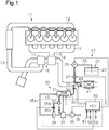
- an exhaust purifying system comprises a selective reduction catalyst provided on an exhaust passage of an engine, a fluid supply device for supplying a urea fluid to a section of the exhaust passage that is upstream of the selective reduction catalyst, a gas separator for separating source gas into oxygen-enriched gas and nitrogen-enriched gas, an ozone generator that includes an ozone producing space, to which the oxygen-enriched gas is introduced, and produces ozone from the introduced oxygen-enriched gas, an ozone supplier for supplying ozone to a section of the exhaust passage that is upstream of the selective reduction catalyst, a vortex tube for separating the nitrogen-enriched gas into cool air and warm air and discharging the cool air and the warm air, and a cooling device for cooling the ozone producing space by applying the cool air discharged from the vortex tube to the ozone generator.
- the exhaust purifying system is installed in a vehicle equipped with a diesel engine.
- an engine 11 includes an intake manifold 12 and an exhaust manifold 14.
- the intake manifold 12 is connected to an intake passage 13, and the exhaust manifold 14 is connected to an exhaust passage 15.
- a compressor 17 of a turbocharger 16 is arranged on the intake passage 13, and the turbine 18 of the turbocharger 16 is arranged on the exhaust passage 15.
- An exhaust purifying system 20 is arranged downstream of the turbine 18 on the exhaust passage 15.
- the exhaust purifying system 20 includes an oxidation catalyst (not shown), a diesel particulate filter (DPF) (not shown), and a selective reduction catalyst 21 on the exhaust passage 15.
- the selective reduction catalyst 21 is arranged downstream of the oxidation catalyst and the DPF on the exhaust passage 15.
- the selective reduction catalyst 21 is a commonly-known catalyst and, for example, made from zeolite or zirconia supported by a honeycomb carrier.
- the exhaust purifying system 20 further includes a urea solution supply device 22 as a fluid supply device, an ozone producing device 30, and an ECU 50 for controlling the devices.
- the urea solution supply device 22 supplies a urea solution as a urea fluid.
- the ozone producing device 30 produces ozone from source gas and supplies the produced ozone to a section of the exhaust passage 15 that is upstream of the selective reduction catalyst 21.
- the urea solution supply device 22 stores a urea solution and supplies the urea solution to a section of the exhaust passage 15 that is upstream of the selective reduction catalyst 21.
- the urea solution is hydrolyzed with heat of the exhaust gas to produce ammonia (NH 3 ).
- the ammonia reacts with nitric monoxide and nitric dioxide that are contained in the exhaust gas and reduces those to nitrogen (gaseous nitrogen) as shown in the reaction formula (2).
- this reduction reaction accelerates as the ratio of NO:NO 2 approaches to 1:1. This is because the ratio is made close to 1:1 by adding ozone and oxidizing NO to NO 2 .
- the urea solution supply device 22 includes a urea solution tank 23 for storing a urea solution, a urea solution supply nozzle 24 for adding the urea solution to a section upstream of the selective reduction catalyst 21, and a urea solution supply passage 25 for connecting the urea solution tank 23 to the urea solution supply nozzle 24.
- a pump 26 for pumping the urea solution from the urea solution tank 23 to the urea solution supply nozzle 24 and a flow rate regulating valve 27 for adjusting a supply amount of urea solution are arranged on the urea solution supply passage 25.
- the ECU 50 drives the pump 26 and controls the opening amount of the flow rate regulating valve 27.
- the ECU 50 also applies a drive pulse to the urea solution supply nozzle 24. When receiving a drive pulse, the urea solution supply nozzle 24 is opened to inject the urea solution to the exhaust passage 15.
- the ozone producing device 30 includes an ozone generator 31 having an ozone producing space.
- the ozone generator 31 is a device having a commonly-known structure such as electron irradiation, irradiation-induce, light irradiation, or electrolysis type.
- the present embodiment employs an electrostatic discharge type device.
- the ozone generator 31 includes a pair of electrode plates arranged with the ozone producing space in between, a dielectric lying between the electrode plates, and an AC high-voltage power supply. Ozone is generated from oxygen (gaseous oxygen) present in the ozone producing space by applying a high voltage across the electrode plates by the AC high-voltage power supply.
- An air introduction passage 35 is connected to the upstream of the ozone generator 31.
- the first end of the air introduction passage 35 opens to the atmosphere, and air as source gas is drawn into the air introduction passage 35 from the outside through the first end.
- a compressor 36, a dryer 37, and an oxygen enrichment unit 38 as a gas separator are arranged on the air introduction passage 35 in that order from the first end.
- the compressor 36 compresses air introduced from the first end of the air introduction passage 35 and introduces the air to the dryer 37.
- the dryer 37 is a dryer that uses a hollow fiber membrane. The dryer 37 dries the compressed air and supplies it to the oxygen enrichment unit 38.
- the oxygen enrichment unit 38 has an oxygen-enriched film.
- the oxygen-enriched film has higher oxygen permeability than nitrogen permeability. That is, oxygen permeates through the oxygen-enriched film at a higher speed than the speed at which nitrogen permeates through the oxygen-enriched film.
- the oxygen-enriched film separates the compressed air into oxygen-enriched gas as high oxygen concentration gas and nitrogen-enriched gas as high nitrogen concentration gas by this difference of the permeation speeds.
- the oxygen-enriched film does not completely separate the compressed air into oxygen and nitrogen. For example, when compressed air having an oxygen concentration of 20% permeates through the oxygen-enriched film, the oxygen concentration increases to be approximately 35%.
- the primary pressure of the oxygen-enriched film is from 0.5 MPa to 1 MPa, the back pressure of the oxygen-enriched film reaches to a value from 0.4 to 0.6 kPa.
- the ECU 50 estimates the ratio of NO:NO 2 based on comparison of the engine operating condition at the moment with the stored map and computes an ozone supply amount from the ratio and others.
- the ECU 50 drives the compressor 36 on a condition according to the computed ozone supply amount.
- the ozone producing device 30 includes a cooling device 40 for cooling the ozone generator 31.
- the cooling device 40 includes the compressor 36, the dryer 37, and a vortex tube 41. That is, the compressor 36 and the dryer 37 also function as the cooling device 40 of the ozone generator 31.
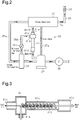
- the second supply passage 35b branched off from the oxygen enrichment unit 38 is connected to an inlet 41 b of the vortex tube 41.
- the vortex tube 41 includes a tube 41a, an inlet 41 b, a cool air outlet 41 c, and a warm air outlet 41d.
- a flow passage 41f is defined in the tube 41a and connected to the inlet 41 b, the cool air outlet 41 c, and the warm air outlet 41d.
- nitrogen-enriched gas is introduced from the inlet 41b and is supplied to the flow passage 41f.
- the nitrogen-enriched gas rotates in a spiral manner at a high speed and is separated into warm and cool air near the warm air outlet 41d.
- the warm air is ejected from the warm air outlet 41d.
- the warm air outlet 41d is connected to the dryer 37. While outside air pumped by the compressor 36 passes through a flow passage in the dryer, the warm air brought back to the dryer 37 travels through a flow passage different from the flow passage of the outside air and is discharged out of the dryer with water separated in the dryer. The cool air turns back before the warm air outlet 41d and travels in the reversed direction while rotating in the flow passage 41f. The cool air is discharged from the cool air outlet 41c.
- the cool air outlet 41c is connected to the ozone generator 31 via the cool air passage 41 e.
- the warm air brought back to the dryer 37 from the vortex tube 41 pushes out drain water discharged from the dryer 37 to a drain water supply passage 37a.
- the "drain water” described here is water discharged from the dryer 37 and includes water in a liquid state, water in a gas state (i.e., water vapor), or both.
- the exit of the drain water supply passage 37a is connected to the ozone generator 31 at a different position from that of the first supply passage 35a.
- the ozone generator 31 includes a body 31a, which accommodates electrodes, and an absorbent material 31b arranged outside of the body 31a.
- a housing of the body 31a is highly resistant to ozone and made of a metallic material having high thermal conductivity.
- the absorbent material 31b is a plate-like member sized the same as a wall of the housing and formed from a substance having high moisture absorbency such as a zeolite, zirconia, or porous graphite material.
- the exit of the drain water supply passage 37a is arranged near the absorbent material 31 b.
- the exit of the drain water supply passage 37a is arranged to contact to the absorbent material 31b or is arranged near the face of the absorbent material 31 b.
- the drain water discharged from the exit of the drain water supply passage 37a is poured in the absorbent material 31 b.
- the absorbent material 31b receives and absorbs the poured drain water.
- the drain water discharged to the absorbent material 31b permeates the entire absorbent material 31b from the poured place.
- the dried cool air is ejected onto the absorbent material 31b soaked with drain water to cool the absorbent material 31b and vaporize the drain water. Ejection of the cool air onto the ozone generator 31 alone cools the ozone producing space. However, vaporization of the drain water of the absorbent material 31b removes heat from the absorbent material 31 b and further cools the absorbent material 31 b. The ejected cool air is dry, and this promotes vaporization of the drain water.
- the body 31a of the ozone generator 31 is entirely cooled by the cooled absorbent material 31 b, and the ozone producing space is cooled by the electrodes, which are accommodated by the body 31a.
- Self-decomposition of ozone is promoted at near 40 degrees C (i.e., the self-decomposition speed is increased), and production efficiency of ozone is increased at a low temperature.
- the vortex tube 41 is long and thin and has the length of a few hundreds millimeters, for example. This supresses size increase of the cooling device 40.
- the ECU 50 starts driving the ozone producing device 30 based on an exhaust gas temperature.
- the ECU 50 drives the ozone producing device 30 when an exhaust gas temperature obtained from the temperature sensor 51 is a low temperature of 200 degrees C or less.
- the ECU 50 stops the ozone producing device 30. This is because, when the exhaust gas temperature exceeds 200 degrees C, reduction reaction of NO x promptly progresses by the selective reduction catalyst 21 without converting a portion of NO contained in the exhaust gas to NO 2 , and NO x reacts with ammonia to be promptly reduced to N 2 .
- the ECU 50 estimates the amount of NO discharged from the engine 11 per unit time based on the ratio map and the operating condition of the engine 11, which are stored in a memory.
- the ECU 50 computes an ozone mass equivalent to the amount of NO or a predetermined portion of the ozone mass relative to the amount of NO as an ozone supply amount per unit time, and adjusts the compressor flow rate and the opening amount of the flow rate regulating valve 34 based on the computed ozone supply amount.
- the ECU 50 sets the frequency of a pulse applied to the electrodes of the ozone generator 31 and the electric discharge condition of output power and the like based on the computed ozone supply amount.
- the ECU 50 drives the pump 26, controls the opening amount of the flow rate regulating valve 27 according to the ejection amount, and applies a drive pulse to the urea solution supply nozzle 24.
- the urea solution supply nozzle 24 is opened with the drive pulse, and the urea solution is injected to the exhaust passage 15.
- outside air is introduced through the inlet of the air introduction passage 35 and pumped to the dryer 37.
- Dry air dried by the dryer 37 is supplied to the oxygen enrichment unit 38, which separates the dry air into oxygen-enriched gas and nitrogen-enriched gas.
- the oxygen-enriched gas is introduced to the space between the electrodes of the ozone generator 31. Excitation or dissociation of oxygen molecules occurs by electric discharge between the electrodes to produce ozone.
- the produced ozone is sent to the ozone supply nozzle 32 through the ozone supply passage 33.
- the ECU 50 applies a drive pulse to the ozone supply nozzle 32 at predetermined intervals.
- the ozone supply nozzle 32 is opened with the received drive pulse to inject the ozone to the exhaust passage 15.
- the ECU 50 When driving the ozone generator 31, the ECU 50 puts the flow rate regulating valve 35c arranged on the second supply passage 35b into an open state. Nitrogen-enriched gas supplied to the second supply passage 35b is introduced to the inside of the vortex tube 41 from the inlet 41 b of the vortex tube 41.
- the drain water discharged from the dryer 37 is poured out to the absorbent material 31 b through the drain water supply passage 37a.
- the absorbent material 31 b is cooled by the cool air pumped from the vortex tube 41 and is further cooled by the effect of heat of evaporation of the drain water.
- the absorbent material 31b absorbs heat of the ozone generator 31 and cools the ozone producing space via the housing of the body 31a.
- the decreased temperature of the ozone producing space results in supressing self-decomposition of ozone and increasing ozone production efficiency.
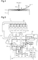
- FIG. 5 A second embodiment of the present invention will now be described with reference to Figs. 5 and 6 .
- the ozone producing device in the first embodiment is replaced with an ozone producing device 30.
- Like reference characters designate like or corresponding parts and the parts will not be described in detail.
- a warm air outlet 42d of the first vortex tube 42 is connected to the warm air passage 43.
- the warm air passage 43 is connected to a heat exchanger 23a arranged on the outer circumference of the urea solution tank 23.
- the heat exchanger 23a exchanges heat between warm air and the urea solution tank 23 and heats a urea solution or keeps it warm.
- a urea solution is frozen in a cold environment, e.g., at a temperature such as minus 12 degrees C, and freezing of the urea solution is prevented by exchanging heat with the heat exchanger 23a.
- a three-way valve 43a is also arranged on the warm air passage 43.
- the warm air outlets 41d and 42d are connected to the engine 11 by opening the valve 43a.
- the warm air outlets 41d and 42d are connected to the outside by closing the valve 43a. This allows the ECU 50 to control opening and closing of the valve 43a to connect the warm air outlets 41d and 42d with the urea solution tank 23 only when there is a need to increase the temperature of the urea solution.
- the cool air outlet 41c of the second vortex tube 41 is connected to the absorbent material 31 b of the ozone generator 31 via the second supply passage 35b in the same way as the first embodiment.
- the warm air outlet 41d is connected to the warm air passage 43. Therefore, effective utilization of warm air discharged from the two vortex tubes 41 and 42 prevents freezing of urea.
- FIG. 7 A third embodiment of the present invention will now be described with reference to Fig. 7 .
- the ozone producing device in the second embodiment is replaced with an ozone producing device 30.
- Like reference characters designate like or corresponding parts and the parts will not be described in detail.
- the second vortex tube 41 is arranged on the second supply passage 35b, through which nitrogen-enriched gas is pumped, and the first vortex tube 42 is arranged on the first supply passage 35a, through which oxygen-enriched gas is pumped.
- the inlet 42b of the first vortex tube 42 is connected to the oxygen enrichment unit 38 via the first supply passage 35a.
- the cool air outlet 42c of the first vortex tube 42 is connected to the ozone generator 31 via the first supply passage 35a. Therefore, cool air from the first vortex tube 42, i.e., cooled oxygen-enriched gas, is introduced to the ozone generator 31.
- the warm air outlet 42d of the first vortex tube 42 is connected to the engine 11 via the warm air passage 43.
- the exit of the warm air passage 43 is connected to a cylinder head 11a of the engine 11.
- the cylinder head 11a includes a flow passage through which warm air passes to exchange heat between the warm air and the cylinder head 11a.
- the three-way valve 43a is arranged on the warm air passage 43.
- the warm air outlet 42d is connected to the engine 11 by opening the valve 43a, and the warm air outlet 42d is connected to the outside by closing the valve 43a. This allows the ECU 50 to control opening and closing of the valve 43a to connect the warm air outlet 42d with the engine 11 only when there is a need to warm up the engine 11.
- the cool air outlet 41c of the second vortex tube 41 is connected to the absorbent material 31 b of the ozone generator 31 via the second supply passage 35b in the same way as the first embodiment.
- the warm air outlet 41d is connected to the cylinder head 11a of the engine 11 via the warm air passage 43.
- the following advantage is obtained in addition to the advantages (1) and (2) described in the first embodiment and the advantage (4) described in the second embodiment.
Landscapes
- Chemical & Material Sciences (AREA)
- Engineering & Computer Science (AREA)
- Organic Chemistry (AREA)
- Chemical Kinetics & Catalysis (AREA)
- Inorganic Chemistry (AREA)
- Health & Medical Sciences (AREA)
- Combustion & Propulsion (AREA)
- Materials Engineering (AREA)
- Environmental & Geological Engineering (AREA)
- Electrochemistry (AREA)
- Mechanical Engineering (AREA)
- Metallurgy (AREA)
- Toxicology (AREA)
- Biomedical Technology (AREA)
- General Engineering & Computer Science (AREA)
- Analytical Chemistry (AREA)
- General Chemical & Material Sciences (AREA)
- Oil, Petroleum & Natural Gas (AREA)
- Exhaust Gas After Treatment (AREA)
- Exhaust Gas Treatment By Means Of Catalyst (AREA)
- Oxygen, Ozone, And Oxides In General (AREA)
Applications Claiming Priority (2)
| Application Number | Priority Date | Filing Date | Title |
|---|---|---|---|
| JP2013018136A JP5719857B2 (ja) | 2013-02-01 | 2013-02-01 | 排気浄化システム及びオゾン生成装置 |
| PCT/JP2014/052058 WO2014119651A1 (ja) | 2013-02-01 | 2014-01-30 | 排気浄化システム及びオゾン生成装置 |
Publications (3)
| Publication Number | Publication Date |
|---|---|
| EP2942503A1 EP2942503A1 (en) | 2015-11-11 |
| EP2942503A4 EP2942503A4 (en) | 2016-03-23 |
| EP2942503B1 true EP2942503B1 (en) | 2017-05-03 |
Family
ID=51262362
Family Applications (1)
| Application Number | Title | Priority Date | Filing Date |
|---|---|---|---|
| EP14746671.8A Not-in-force EP2942503B1 (en) | 2013-02-01 | 2014-01-30 | Exhaust gas purification system and ozone generator |
Country Status (5)
| Country | Link |
|---|---|
| US (1) | US9504961B2 (enExample) |
| EP (1) | EP2942503B1 (enExample) |
| JP (1) | JP5719857B2 (enExample) |
| CN (1) | CN104956040B (enExample) |
| WO (1) | WO2014119651A1 (enExample) |
Families Citing this family (18)
| Publication number | Priority date | Publication date | Assignee | Title |
|---|---|---|---|---|
| JP6176279B2 (ja) * | 2015-03-27 | 2017-08-09 | マツダ株式会社 | 多気筒エンジンの排気装置 |
| CN105041432B (zh) * | 2015-08-06 | 2018-03-13 | 茵卡排放控制系统(江苏)有限公司 | Scr系统尿素喷嘴的防结晶装置 |
| ITUB20155040A1 (it) * | 2015-10-23 | 2017-04-23 | Irca Spa | Dispositivo per la depurazione dei gas di scarico da motori endotermici |
| JP6610318B2 (ja) * | 2016-02-11 | 2019-11-27 | 株式会社デンソー | オゾン供給制御装置およびオゾン供給システム |
| US9926825B2 (en) * | 2016-04-19 | 2018-03-27 | GM Global Technology Operations LLC | Method and apparatus for exhaust purification for an internal combustion engine |
| JP2018154265A (ja) * | 2017-03-17 | 2018-10-04 | 本田技研工業株式会社 | 車両用ウォッシャ装置 |
| US10378427B2 (en) * | 2017-03-31 | 2019-08-13 | Saudi Arabian Oil Company | Nitrogen enriched air supply for gasoline compression ignition combustion |
| KR101980433B1 (ko) * | 2017-05-15 | 2019-05-21 | 한국기계연구원 | 고효율 오존발생시스템 |
| JP6922586B2 (ja) * | 2017-09-19 | 2021-08-18 | 株式会社デンソー | オゾン発生システム |
| CN107917463A (zh) * | 2017-09-27 | 2018-04-17 | 常州信息职业技术学院 | 一种改进的空气净化装置 |
| CN107983121B (zh) * | 2017-12-21 | 2020-07-31 | 重庆凯杰林环保工程有限公司 | 一种烟尘回收处理环保装置 |
| US20190383189A1 (en) * | 2018-06-13 | 2019-12-19 | Deere & Company | Exhaust gas treatment system with improved low temperature performance |
| EP3626327B1 (de) * | 2018-09-19 | 2023-11-01 | Wagner Group GmbH | Inertisierungsverfahren und inertisierungsanlage, insbesondere zur brandvermeidung, sowie verwendung einer inertisierungsanlage |
| CN109939533B (zh) * | 2019-04-23 | 2025-06-10 | 江苏博润通科技有限公司 | 一种带有自动报警功能的气体干燥装置 |
| CN112473345B (zh) * | 2020-10-23 | 2021-08-24 | 三河市清源绿创环境技术股份有限公司 | 一种气体发生系统 |
| CN113606015A (zh) * | 2021-08-10 | 2021-11-05 | 北京工业大学 | 一种基于臭氧进行的dpf主动再生的装置及方法 |
| CN114856782B (zh) * | 2022-04-01 | 2023-08-08 | 三河市科达科技有限公司 | 一种基于废气涡流加热与电加热相结合的dpf再生装置 |
| JP2023183958A (ja) * | 2022-06-17 | 2023-12-28 | ウシオ電機株式会社 | オゾン含有ガス発生方法、オゾン含有ガス発生システム |
Family Cites Families (13)
| Publication number | Priority date | Publication date | Assignee | Title |
|---|---|---|---|---|
| US3884819A (en) * | 1974-08-19 | 1975-05-20 | Ozone Inc | Gas cooling and drying system for corona discharge ozone generating unit |
| JPH0624710A (ja) * | 1992-07-03 | 1994-02-01 | Ebara Corp | オゾン発生装置 |
| US5611845A (en) * | 1995-08-22 | 1997-03-18 | Undersea Breathing Systems, Inc. | Oxygen enriched air generation system |
| US6193852B1 (en) * | 1997-05-28 | 2001-02-27 | The Boc Group, Inc. | Ozone generator and method of producing ozone |
| US5992464A (en) * | 1998-01-09 | 1999-11-30 | Cowell; Ross A. | Pre-compression nitrox in-line blender |
| US6959538B2 (en) * | 2002-12-06 | 2005-11-01 | General Motors Corporation | Ultra low power plasma reactor system for automotive NOx emission control |
| US20040188238A1 (en) * | 2003-03-28 | 2004-09-30 | Hemingway Mark David | System and method for concurrent particulate and NOx control |
| EP1736175A4 (en) * | 2004-03-31 | 2009-07-29 | Yuyama Mfg Co Ltd | STERILIZATION METHOD AND APPARATUS THEREFOR |
| US7368094B2 (en) * | 2004-09-23 | 2008-05-06 | General Motors Corporation | Plasma-assisted NOx reduction |
| US7790127B1 (en) * | 2009-03-02 | 2010-09-07 | Gm Global Technology Operations, Inc. | NOx emission control system for hydrocarbon fueled power source |
| JP2012193620A (ja) | 2011-03-15 | 2012-10-11 | Hino Motors Ltd | 排ガス浄化装置 |
| WO2012124531A1 (ja) * | 2011-03-15 | 2012-09-20 | 日野自動車株式会社 | 排ガス浄化装置 |
| JP2013010647A (ja) | 2011-06-28 | 2013-01-17 | Hino Motors Ltd | オゾン発生装置 |
-
2013
- 2013-02-01 JP JP2013018136A patent/JP5719857B2/ja active Active
-
2014
- 2014-01-30 CN CN201480006611.5A patent/CN104956040B/zh not_active Expired - Fee Related
- 2014-01-30 EP EP14746671.8A patent/EP2942503B1/en not_active Not-in-force
- 2014-01-30 US US14/762,913 patent/US9504961B2/en not_active Expired - Fee Related
- 2014-01-30 WO PCT/JP2014/052058 patent/WO2014119651A1/ja not_active Ceased
Non-Patent Citations (1)
| Title |
|---|
| None * |
Also Published As
| Publication number | Publication date |
|---|---|
| WO2014119651A1 (ja) | 2014-08-07 |
| EP2942503A1 (en) | 2015-11-11 |
| EP2942503A4 (en) | 2016-03-23 |
| CN104956040A (zh) | 2015-09-30 |
| JP5719857B2 (ja) | 2015-05-20 |
| US20150360177A1 (en) | 2015-12-17 |
| US9504961B2 (en) | 2016-11-29 |
| JP2014148937A (ja) | 2014-08-21 |
| CN104956040B (zh) | 2017-05-24 |
Similar Documents
| Publication | Publication Date | Title |
|---|---|---|
| EP2942503B1 (en) | Exhaust gas purification system and ozone generator | |
| US9156000B2 (en) | Exhaust gas purifier | |
| WO2012124531A1 (ja) | 排ガス浄化装置 | |
| US9145805B2 (en) | Exhaust gas purifier | |
| US20100199643A1 (en) | Exhaust gas purification system | |
| JP2004270565A (ja) | ディーゼルエンジンの排ガス浄化システム | |
| JP2012193620A (ja) | 排ガス浄化装置 | |
| JP2014047670A (ja) | オゾン生成手段を含むエンジン用NOx後処理装置の制御方法および制御装置 | |
| JP5711578B2 (ja) | 尿素水改質器及びこれを用いた排ガス浄化装置 | |
| JP2013010647A (ja) | オゾン発生装置 | |
| KR101461289B1 (ko) | 구조가 개선된 선택적 촉매 환원 반응기 | |
| JP5952533B2 (ja) | 排ガス浄化装置 | |
| JP6050942B2 (ja) | 排ガス浄化装置 | |
| JP5865074B2 (ja) | 排ガス浄化装置 | |
| JP2014227852A (ja) | 排気浄化システム | |
| JP7340395B2 (ja) | 内燃機関システム | |
| KR20170127544A (ko) | 발전 기능을 갖춘 배기가스 정화 시스템 | |
| JP2014122551A (ja) | 排ガス浄化装置 |
Legal Events
| Date | Code | Title | Description |
|---|---|---|---|
| PUAI | Public reference made under article 153(3) epc to a published international application that has entered the european phase |
Free format text: ORIGINAL CODE: 0009012 |
|
| 17P | Request for examination filed |
Effective date: 20150724 |
|
| AK | Designated contracting states |
Kind code of ref document: A1 Designated state(s): AL AT BE BG CH CY CZ DE DK EE ES FI FR GB GR HR HU IE IS IT LI LT LU LV MC MK MT NL NO PL PT RO RS SE SI SK SM TR |
|
| AX | Request for extension of the european patent |
Extension state: BA ME |
|
| A4 | Supplementary search report drawn up and despatched |
Effective date: 20160223 |
|
| RIC1 | Information provided on ipc code assigned before grant |
Ipc: C01B 13/10 20060101ALI20160217BHEP Ipc: F01N 3/08 20060101AFI20160217BHEP Ipc: B01D 53/94 20060101ALI20160217BHEP |
|
| DAX | Request for extension of the european patent (deleted) | ||
| GRAP | Despatch of communication of intention to grant a patent |
Free format text: ORIGINAL CODE: EPIDOSNIGR1 |
|
| INTG | Intention to grant announced |
Effective date: 20170203 |
|
| RIN1 | Information on inventor provided before grant (corrected) |
Inventor name: TSUMAGARI, ICHIRO Inventor name: KAWADA, YOSHIHIRO |
|
| GRAS | Grant fee paid |
Free format text: ORIGINAL CODE: EPIDOSNIGR3 |
|
| GRAA | (expected) grant |
Free format text: ORIGINAL CODE: 0009210 |
|
| AK | Designated contracting states |
Kind code of ref document: B1 Designated state(s): AL AT BE BG CH CY CZ DE DK EE ES FI FR GB GR HR HU IE IS IT LI LT LU LV MC MK MT NL NO PL PT RO RS SE SI SK SM TR |
|
| REG | Reference to a national code |
Ref country code: GB Ref legal event code: FG4D |
|
| REG | Reference to a national code |
Ref country code: AT Ref legal event code: REF Ref document number: 890250 Country of ref document: AT Kind code of ref document: T Effective date: 20170515 Ref country code: CH Ref legal event code: EP |
|
| REG | Reference to a national code |
Ref country code: IE Ref legal event code: FG4D |
|
| REG | Reference to a national code |
Ref country code: DE Ref legal event code: R096 Ref document number: 602014009454 Country of ref document: DE |
|
| REG | Reference to a national code |
Ref country code: NL Ref legal event code: MP Effective date: 20170503 |
|
| REG | Reference to a national code |
Ref country code: AT Ref legal event code: MK05 Ref document number: 890250 Country of ref document: AT Kind code of ref document: T Effective date: 20170503 |
|
| REG | Reference to a national code |
Ref country code: LT Ref legal event code: MG4D |
|
| PG25 | Lapsed in a contracting state [announced via postgrant information from national office to epo] |
Ref country code: HR Free format text: LAPSE BECAUSE OF FAILURE TO SUBMIT A TRANSLATION OF THE DESCRIPTION OR TO PAY THE FEE WITHIN THE PRESCRIBED TIME-LIMIT Effective date: 20170503 Ref country code: FI Free format text: LAPSE BECAUSE OF FAILURE TO SUBMIT A TRANSLATION OF THE DESCRIPTION OR TO PAY THE FEE WITHIN THE PRESCRIBED TIME-LIMIT Effective date: 20170503 Ref country code: NO Free format text: LAPSE BECAUSE OF FAILURE TO SUBMIT A TRANSLATION OF THE DESCRIPTION OR TO PAY THE FEE WITHIN THE PRESCRIBED TIME-LIMIT Effective date: 20170803 Ref country code: AT Free format text: LAPSE BECAUSE OF FAILURE TO SUBMIT A TRANSLATION OF THE DESCRIPTION OR TO PAY THE FEE WITHIN THE PRESCRIBED TIME-LIMIT Effective date: 20170503 Ref country code: LT Free format text: LAPSE BECAUSE OF FAILURE TO SUBMIT A TRANSLATION OF THE DESCRIPTION OR TO PAY THE FEE WITHIN THE PRESCRIBED TIME-LIMIT Effective date: 20170503 Ref country code: ES Free format text: LAPSE BECAUSE OF FAILURE TO SUBMIT A TRANSLATION OF THE DESCRIPTION OR TO PAY THE FEE WITHIN THE PRESCRIBED TIME-LIMIT Effective date: 20170503 Ref country code: GR Free format text: LAPSE BECAUSE OF FAILURE TO SUBMIT A TRANSLATION OF THE DESCRIPTION OR TO PAY THE FEE WITHIN THE PRESCRIBED TIME-LIMIT Effective date: 20170804 |
|
| PG25 | Lapsed in a contracting state [announced via postgrant information from national office to epo] |
Ref country code: IS Free format text: LAPSE BECAUSE OF FAILURE TO SUBMIT A TRANSLATION OF THE DESCRIPTION OR TO PAY THE FEE WITHIN THE PRESCRIBED TIME-LIMIT Effective date: 20170903 Ref country code: LV Free format text: LAPSE BECAUSE OF FAILURE TO SUBMIT A TRANSLATION OF THE DESCRIPTION OR TO PAY THE FEE WITHIN THE PRESCRIBED TIME-LIMIT Effective date: 20170503 Ref country code: PL Free format text: LAPSE BECAUSE OF FAILURE TO SUBMIT A TRANSLATION OF THE DESCRIPTION OR TO PAY THE FEE WITHIN THE PRESCRIBED TIME-LIMIT Effective date: 20170503 Ref country code: NL Free format text: LAPSE BECAUSE OF FAILURE TO SUBMIT A TRANSLATION OF THE DESCRIPTION OR TO PAY THE FEE WITHIN THE PRESCRIBED TIME-LIMIT Effective date: 20170503 Ref country code: RS Free format text: LAPSE BECAUSE OF FAILURE TO SUBMIT A TRANSLATION OF THE DESCRIPTION OR TO PAY THE FEE WITHIN THE PRESCRIBED TIME-LIMIT Effective date: 20170503 Ref country code: BG Free format text: LAPSE BECAUSE OF FAILURE TO SUBMIT A TRANSLATION OF THE DESCRIPTION OR TO PAY THE FEE WITHIN THE PRESCRIBED TIME-LIMIT Effective date: 20170803 Ref country code: SE Free format text: LAPSE BECAUSE OF FAILURE TO SUBMIT A TRANSLATION OF THE DESCRIPTION OR TO PAY THE FEE WITHIN THE PRESCRIBED TIME-LIMIT Effective date: 20170503 |
|
| PG25 | Lapsed in a contracting state [announced via postgrant information from national office to epo] |
Ref country code: EE Free format text: LAPSE BECAUSE OF FAILURE TO SUBMIT A TRANSLATION OF THE DESCRIPTION OR TO PAY THE FEE WITHIN THE PRESCRIBED TIME-LIMIT Effective date: 20170503 Ref country code: RO Free format text: LAPSE BECAUSE OF FAILURE TO SUBMIT A TRANSLATION OF THE DESCRIPTION OR TO PAY THE FEE WITHIN THE PRESCRIBED TIME-LIMIT Effective date: 20170503 Ref country code: DK Free format text: LAPSE BECAUSE OF FAILURE TO SUBMIT A TRANSLATION OF THE DESCRIPTION OR TO PAY THE FEE WITHIN THE PRESCRIBED TIME-LIMIT Effective date: 20170503 Ref country code: CZ Free format text: LAPSE BECAUSE OF FAILURE TO SUBMIT A TRANSLATION OF THE DESCRIPTION OR TO PAY THE FEE WITHIN THE PRESCRIBED TIME-LIMIT Effective date: 20170503 Ref country code: SK Free format text: LAPSE BECAUSE OF FAILURE TO SUBMIT A TRANSLATION OF THE DESCRIPTION OR TO PAY THE FEE WITHIN THE PRESCRIBED TIME-LIMIT Effective date: 20170503 |
|
| REG | Reference to a national code |
Ref country code: DE Ref legal event code: R097 Ref document number: 602014009454 Country of ref document: DE |
|
| PG25 | Lapsed in a contracting state [announced via postgrant information from national office to epo] |
Ref country code: IT Free format text: LAPSE BECAUSE OF FAILURE TO SUBMIT A TRANSLATION OF THE DESCRIPTION OR TO PAY THE FEE WITHIN THE PRESCRIBED TIME-LIMIT Effective date: 20170503 Ref country code: SM Free format text: LAPSE BECAUSE OF FAILURE TO SUBMIT A TRANSLATION OF THE DESCRIPTION OR TO PAY THE FEE WITHIN THE PRESCRIBED TIME-LIMIT Effective date: 20170503 |
|
| PLBE | No opposition filed within time limit |
Free format text: ORIGINAL CODE: 0009261 |
|
| STAA | Information on the status of an ep patent application or granted ep patent |
Free format text: STATUS: NO OPPOSITION FILED WITHIN TIME LIMIT |
|
| 26N | No opposition filed |
Effective date: 20180206 |
|
| PG25 | Lapsed in a contracting state [announced via postgrant information from national office to epo] |
Ref country code: SI Free format text: LAPSE BECAUSE OF FAILURE TO SUBMIT A TRANSLATION OF THE DESCRIPTION OR TO PAY THE FEE WITHIN THE PRESCRIBED TIME-LIMIT Effective date: 20170503 |
|
| REG | Reference to a national code |
Ref country code: CH Ref legal event code: PL |
|
| PG25 | Lapsed in a contracting state [announced via postgrant information from national office to epo] |
Ref country code: FR Free format text: LAPSE BECAUSE OF NON-PAYMENT OF DUE FEES Effective date: 20180131 Ref country code: LU Free format text: LAPSE BECAUSE OF NON-PAYMENT OF DUE FEES Effective date: 20180130 |
|
| REG | Reference to a national code |
Ref country code: IE Ref legal event code: MM4A |
|
| REG | Reference to a national code |
Ref country code: FR Ref legal event code: ST Effective date: 20180928 |
|
| REG | Reference to a national code |
Ref country code: BE Ref legal event code: MM Effective date: 20180131 |
|
| PG25 | Lapsed in a contracting state [announced via postgrant information from national office to epo] |
Ref country code: LI Free format text: LAPSE BECAUSE OF NON-PAYMENT OF DUE FEES Effective date: 20180131 Ref country code: CH Free format text: LAPSE BECAUSE OF NON-PAYMENT OF DUE FEES Effective date: 20180131 Ref country code: BE Free format text: LAPSE BECAUSE OF NON-PAYMENT OF DUE FEES Effective date: 20180131 |
|
| PG25 | Lapsed in a contracting state [announced via postgrant information from national office to epo] |
Ref country code: IE Free format text: LAPSE BECAUSE OF NON-PAYMENT OF DUE FEES Effective date: 20180130 |
|
| PGFP | Annual fee paid to national office [announced via postgrant information from national office to epo] |
Ref country code: DE Payment date: 20190111 Year of fee payment: 6 Ref country code: GB Payment date: 20190128 Year of fee payment: 6 |
|
| PG25 | Lapsed in a contracting state [announced via postgrant information from national office to epo] |
Ref country code: MC Free format text: LAPSE BECAUSE OF FAILURE TO SUBMIT A TRANSLATION OF THE DESCRIPTION OR TO PAY THE FEE WITHIN THE PRESCRIBED TIME-LIMIT Effective date: 20170503 |
|
| PG25 | Lapsed in a contracting state [announced via postgrant information from national office to epo] |
Ref country code: MT Free format text: LAPSE BECAUSE OF NON-PAYMENT OF DUE FEES Effective date: 20180130 |
|
| PG25 | Lapsed in a contracting state [announced via postgrant information from national office to epo] |
Ref country code: TR Free format text: LAPSE BECAUSE OF FAILURE TO SUBMIT A TRANSLATION OF THE DESCRIPTION OR TO PAY THE FEE WITHIN THE PRESCRIBED TIME-LIMIT Effective date: 20170503 |
|
| PG25 | Lapsed in a contracting state [announced via postgrant information from national office to epo] |
Ref country code: PT Free format text: LAPSE BECAUSE OF FAILURE TO SUBMIT A TRANSLATION OF THE DESCRIPTION OR TO PAY THE FEE WITHIN THE PRESCRIBED TIME-LIMIT Effective date: 20170503 |
|
| PG25 | Lapsed in a contracting state [announced via postgrant information from national office to epo] |
Ref country code: MK Free format text: LAPSE BECAUSE OF NON-PAYMENT OF DUE FEES Effective date: 20170503 Ref country code: HU Free format text: LAPSE BECAUSE OF FAILURE TO SUBMIT A TRANSLATION OF THE DESCRIPTION OR TO PAY THE FEE WITHIN THE PRESCRIBED TIME-LIMIT; INVALID AB INITIO Effective date: 20140130 Ref country code: CY Free format text: LAPSE BECAUSE OF FAILURE TO SUBMIT A TRANSLATION OF THE DESCRIPTION OR TO PAY THE FEE WITHIN THE PRESCRIBED TIME-LIMIT Effective date: 20170503 |
|
| PG25 | Lapsed in a contracting state [announced via postgrant information from national office to epo] |
Ref country code: AL Free format text: LAPSE BECAUSE OF FAILURE TO SUBMIT A TRANSLATION OF THE DESCRIPTION OR TO PAY THE FEE WITHIN THE PRESCRIBED TIME-LIMIT Effective date: 20170503 |
|
| REG | Reference to a national code |
Ref country code: DE Ref legal event code: R119 Ref document number: 602014009454 Country of ref document: DE |
|
| GBPC | Gb: european patent ceased through non-payment of renewal fee |
Effective date: 20200130 |
|
| PG25 | Lapsed in a contracting state [announced via postgrant information from national office to epo] |
Ref country code: DE Free format text: LAPSE BECAUSE OF NON-PAYMENT OF DUE FEES Effective date: 20200801 Ref country code: GB Free format text: LAPSE BECAUSE OF NON-PAYMENT OF DUE FEES Effective date: 20200130 |