EP2942296A2 - Verfahren und vorrichtung zur herstellung von beuteln für tabakprodukte - Google Patents
Verfahren und vorrichtung zur herstellung von beuteln für tabakprodukte Download PDFInfo
- Publication number
- EP2942296A2 EP2942296A2 EP15000662.5A EP15000662A EP2942296A2 EP 2942296 A2 EP2942296 A2 EP 2942296A2 EP 15000662 A EP15000662 A EP 15000662A EP 2942296 A2 EP2942296 A2 EP 2942296A2
- Authority
- EP
- European Patent Office
- Prior art keywords
- bags
- magazine
- bag
- packaging machine
- feed device
- Prior art date
- Legal status (The legal status is an assumption and is not a legal conclusion. Google has not performed a legal analysis and makes no representation as to the accuracy of the status listed.)
- Granted
Links
Images




Classifications
-
- B—PERFORMING OPERATIONS; TRANSPORTING
- B65—CONVEYING; PACKING; STORING; HANDLING THIN OR FILAMENTARY MATERIAL
- B65B—MACHINES, APPARATUS OR DEVICES FOR, OR METHODS OF, PACKAGING ARTICLES OR MATERIALS; UNPACKING
- B65B43/00—Forming, feeding, opening or setting-up containers or receptacles in association with packaging
- B65B43/04—Forming flat bags from webs
-
- B—PERFORMING OPERATIONS; TRANSPORTING
- B65—CONVEYING; PACKING; STORING; HANDLING THIN OR FILAMENTARY MATERIAL
- B65B—MACHINES, APPARATUS OR DEVICES FOR, OR METHODS OF, PACKAGING ARTICLES OR MATERIALS; UNPACKING
- B65B43/00—Forming, feeding, opening or setting-up containers or receptacles in association with packaging
- B65B43/12—Feeding flexible bags or carton blanks in flat or collapsed state; Feeding flat bags connected to form a series or chain
- B65B43/14—Feeding individual bags or carton blanks from piles or magazines
- B65B43/16—Feeding individual bags or carton blanks from piles or magazines by grippers
- B65B43/18—Feeding individual bags or carton blanks from piles or magazines by grippers by suction-operated grippers
-
- B—PERFORMING OPERATIONS; TRANSPORTING
- B65—CONVEYING; PACKING; STORING; HANDLING THIN OR FILAMENTARY MATERIAL
- B65B—MACHINES, APPARATUS OR DEVICES FOR, OR METHODS OF, PACKAGING ARTICLES OR MATERIALS; UNPACKING
- B65B59/00—Arrangements to enable machines to handle articles of different sizes, to produce packages of different sizes, to vary the contents of packages, to handle different types of packaging material, or to give access for cleaning or maintenance purposes
- B65B59/003—Arrangements to enable adjustments related to the packaging material
-
- B—PERFORMING OPERATIONS; TRANSPORTING
- B65—CONVEYING; PACKING; STORING; HANDLING THIN OR FILAMENTARY MATERIAL
- B65B—MACHINES, APPARATUS OR DEVICES FOR, OR METHODS OF, PACKAGING ARTICLES OR MATERIALS; UNPACKING
- B65B59/00—Arrangements to enable machines to handle articles of different sizes, to produce packages of different sizes, to vary the contents of packages, to handle different types of packaging material, or to give access for cleaning or maintenance purposes
- B65B59/04—Machines constructed with readily-detachable units or assemblies, e.g. to facilitate maintenance
-
- B—PERFORMING OPERATIONS; TRANSPORTING
- B65—CONVEYING; PACKING; STORING; HANDLING THIN OR FILAMENTARY MATERIAL
- B65B—MACHINES, APPARATUS OR DEVICES FOR, OR METHODS OF, PACKAGING ARTICLES OR MATERIALS; UNPACKING
- B65B65/00—Details peculiar to packaging machines and not otherwise provided for; Arrangements of such details
- B65B65/003—Packaging lines, e.g. general layout
-
- B—PERFORMING OPERATIONS; TRANSPORTING
- B65—CONVEYING; PACKING; STORING; HANDLING THIN OR FILAMENTARY MATERIAL
- B65B—MACHINES, APPARATUS OR DEVICES FOR, OR METHODS OF, PACKAGING ARTICLES OR MATERIALS; UNPACKING
- B65B9/00—Enclosing successive articles, or quantities of material, e.g. liquids or semiliquids, in flat, folded, or tubular webs of flexible sheet material; Subdividing filled flexible tubes to form packages
- B65B9/06—Enclosing successive articles, or quantities of material, in a longitudinally-folded web, or in a web folded into a tube about the articles or quantities of material placed upon it
- B65B9/08—Enclosing successive articles, or quantities of material, in a longitudinally-folded web, or in a web folded into a tube about the articles or quantities of material placed upon it in a web folded and sealed transversely to form pockets which are subsequently filled and then closed by sealing
- B65B9/093—Enclosing successive articles, or quantities of material, in a longitudinally-folded web, or in a web folded into a tube about the articles or quantities of material placed upon it in a web folded and sealed transversely to form pockets which are subsequently filled and then closed by sealing the web having intermittent motion
-
- B—PERFORMING OPERATIONS; TRANSPORTING
- B65—CONVEYING; PACKING; STORING; HANDLING THIN OR FILAMENTARY MATERIAL
- B65H—HANDLING THIN OR FILAMENTARY MATERIAL, e.g. SHEETS, WEBS, CABLES
- B65H1/00—Supports or magazines for piles from which articles are to be separated
- B65H1/30—Supports or magazines for piles from which articles are to be separated with means for replenishing the pile during continuous separation of articles therefrom
-
- B—PERFORMING OPERATIONS; TRANSPORTING
- B65—CONVEYING; PACKING; STORING; HANDLING THIN OR FILAMENTARY MATERIAL
- B65H—HANDLING THIN OR FILAMENTARY MATERIAL, e.g. SHEETS, WEBS, CABLES
- B65H5/00—Feeding articles separated from piles; Feeding articles to machines
- B65H5/02—Feeding articles separated from piles; Feeding articles to machines by belts or chains, e.g. between belts or chains
- B65H5/021—Feeding articles separated from piles; Feeding articles to machines by belts or chains, e.g. between belts or chains by belts
- B65H5/023—Feeding articles separated from piles; Feeding articles to machines by belts or chains, e.g. between belts or chains by belts between a pair of belts forming a transport nip
-
- B—PERFORMING OPERATIONS; TRANSPORTING
- B65—CONVEYING; PACKING; STORING; HANDLING THIN OR FILAMENTARY MATERIAL
- B65B—MACHINES, APPARATUS OR DEVICES FOR, OR METHODS OF, PACKAGING ARTICLES OR MATERIALS; UNPACKING
- B65B2210/00—Specific aspects of the packaging machine
- B65B2210/02—Plurality of alternative input or output lines or plurality of alternative packaging units on the same packaging line for improving machine flexibility
-
- B—PERFORMING OPERATIONS; TRANSPORTING
- B65—CONVEYING; PACKING; STORING; HANDLING THIN OR FILAMENTARY MATERIAL
- B65B—MACHINES, APPARATUS OR DEVICES FOR, OR METHODS OF, PACKAGING ARTICLES OR MATERIALS; UNPACKING
- B65B59/00—Arrangements to enable machines to handle articles of different sizes, to produce packages of different sizes, to vary the contents of packages, to handle different types of packaging material, or to give access for cleaning or maintenance purposes
-
- B—PERFORMING OPERATIONS; TRANSPORTING
- B65—CONVEYING; PACKING; STORING; HANDLING THIN OR FILAMENTARY MATERIAL
- B65H—HANDLING THIN OR FILAMENTARY MATERIAL, e.g. SHEETS, WEBS, CABLES
- B65H2801/00—Application field
- B65H2801/54—Cigarette making
Definitions
- the invention relates to a method for the production of bags for tobacco products, being formed by means of a packaging machine from a continuous web of material by folding and sealing the web of bags and the bags formed separated by separating from the web and subsequently filled, according to the preamble of claim 1 Furthermore, the invention relates to a corresponding device according to the preamble of claim 5.
- Bags for tobacco products are known in practice in numerous embodiments, for example as a wrapper, sofalt nitrogen, etc.
- the bags are made in the field on site prior to filling or alternatively supplied as a prefabricated bag and then filled.
- the customer has to decide how he wants to supply the machine with bags. A subsequent conversion of the machine or a corresponding conversion is associated with considerable effort.
- the invention is based on the object to further develop methods and devices of the type mentioned above, in particular with regard to the simplest and most cost-effective convertibility of the packaging machine.
- a method for achieving this object has the features of claim 1. It is accordingly provided that the packaging machine is also assigned a magazine for prefabricated bags, from which the bags are taken alternatively or additionally to the production of the bags on the packaging machine and subsequently filled.
- This solution has the particular advantage that a complex to complex conversion of the packaging machine from a way of providing the bag to another type of provision omitted.
- the bags are taken over by means of at least one feed device either coming from the packaging machine or from the magazine and are preferably fed to a turret for filling.
- the feeder may be configured to selectively accept bags in one of two ways.
- the feeder can also be designed to be exchangeable in a simple manner, so that a change between the two paths is possible in a simple manner.
- the feed device is designed so that in each case a plurality of bags are forwarded for filling in one step, preferably in each case a corresponding number of several bags are filled simultaneously on the turret in one step.
- the bags are fed to the magazine as groups of bags, preferably in compartments of a Mit psychologybandes of the magazine, and that the bag from the magazine, preferably from the subjects of Mit videbandes, by means of a singulator and fed one after the other to the feeder and be handed over to the revolver.
- a device according to the invention for solving the problem set out has the features of claim 5. It is therefore provided that the packaging machine is also associated with a magazine for prefabricated bags, from which the bags can be removed and subsequently filled as an alternative or in addition to the production of the bags on the packaging machine.
- the magazine is slidably mounted in particular for changing between the bag feed from the packaging machine and the bag feed from the magazine, in particular in the longitudinal direction of the magazine preferably by means of a rail guide, wherein the rail guide preferably in a base frame of Device is integrated.
- the device has a feed device, for taking over the bags either from the packaging machine or from the magazine and for transferring the bags preferably to a revolver for filling the bag.
- both the packaging machine and the magazine each have a feed device is assigned, each of which is only for handling bags from the packaging machine or the magazine determined and activated, preferably such that the feeding through the same drive are actuated.
- Another peculiarity may consist in that the magazine is formed by a Mit psychologyband, being formed by drivers of Mit psychologybands subjects or separated and wherein the drivers are held at a distance from the Mit supportiveband on a guide or guided, such that the inclination of the Driver is controlled.
- the bags are removed from the magazine by means of a separating device and transferred to the feeder, wherein in the field of transfer of the bag from the magazine to the singling device another Mit favorband is arranged, such that the bag in the transfer laterally by a driver of the Mit repertoires are supported.
- the Mit supportiveband is arranged circumferentially in a vertical plane, wherein the driver projecting towards the Mit supportiveband outward, and wherein the drivers are pivotally mounted on Mit favorband and are guided at a distance from the Mit supportiveband via roller lever in a curved track, such that the carriers are arranged during the circulation of the Mit supportivebands in predetermined, different inclinations.
- Another special feature may consist in that the bags can be removed from the magazine in the region of an underside of the carrier belt and can be fed along an ascending conveying path in the direction of the feed device, wherein the bags can be conveyed and conveyed in a downwardly directed section of the conveyor line before reaching the feed device the feeder can be handed over.
- the invention will be described below with reference to a packaging machine 11 for (tobacco) bags (10). It is understood that the bags (10) need not necessarily be intended for receiving tobacco products, but may also be suitable for receiving other products.
- Fig. 1 and 2 show two different variants of a bag 10, namely a so-called wrap bag ( Fig. 1 ) or a side-folding bag ( Fig. 2 ) in each case in the open position.
- the bags 10 have a pocket 12 for receiving a bag contents and a (cover) tab 13. Since the basic structure of winding bags and side folding bags is known, will not be discussed further below. In any case, these two bag types are shown only as examples of possible bags 10.
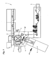
- Fig. 3 shows a schematic overview of a packaging machine 11 for the filling of bags 10.
- the packaging machine 11 on the one hand, a film web 14 are supplied, which is then processed during the further transport path to bags 10.
- the steps required for this purpose are completely known from the prior art, so that a description of the details is omitted.
- the packaging machine 11 has a magazine 15 for bags 10, with which ready-made or prepared for filling bag 10 can be provided.
- the bag 10 produced from the film web 14 and the bag 10 originating from the magazine 15 are fed to a feed device 16, 17, which serves to transfer the bags 10 to a revolver 18.
- a feed device 16, 17 which serves to transfer the bags 10 to a revolver 18.
- the bag 10 are filled in a filling station 19 and then transferred the filled bag 10 from the turret 18 to a conveyor line 20 and transported away.
- the use of a revolver 18 is a preferred solution, but not necessarily for the implementation of the invention.
- a special feature of the packaging machine 11 on the one hand the arrangement of the magazine 15 in addition to the production of the bag 10 from a film web 14.
- bags 10 can be supplied both from the magazine 15 and fed via the production of film web 14.
- the two corresponding conveyor lines both end in the area of the revolver 18, which then fills the bag 10 supplied on one or the other path.
- the bags 10 are alternatively produced only from the film web 14 or removed from the magazine 15. You can then switch between these two alternatives. Furthermore, it is conceivable that the same kind of bag 10 is produced from the film web 14, which is also located in the magazine 15. More likely, however, is that a different type or type of bag 10 is located in the magazine 15 than is produced by the film web 14, so that it is possible to switch between the production of different bags 10.
- the revolver 18 is designed double-lane, so that in a work cycle each two bags 10 passed to the turret 18 and filled after rotation of the revolver 18 in the filling station 19.
- the feeders 16, 17 are pivotally formed, as in Fig. 5 indicated.
- the feeders 16, 17 are pivoted away from the circumference of the revolver 18.
- the feeders 16, 17 are pivoted again against the circumference of the revolver 18. The feeding of the bags 10 to the feeders 16, 17 can take place while these are pivoted away from the circumference of the revolver 18.
- Fig. 11 shows analogously the supply of bags 10 from the magazine 15.
- the supply of the bag 10 made of the film web 14 is not active.
- the feeder 17 has been shut down. In the present case this is due to disassembly the feeding device 17 takes place. Recognizable is only a receptacle 21 for the feeder 17. It is also conceivable only a deactivation.
- the bags 10 are transferred from the magazine coming to the feeder 16, while this is pivoted back from the scope of the revolver 19. Thereafter, the feeder 16 is pivoted against the turret 18, so that the bag 10 can be handed over.
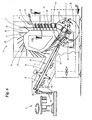
- the magazine 15 is displaceably mounted in the longitudinal direction, namely between a working position ( Fig. 3 and 11 ) and a ready position ( 4 and 5 ). Furthermore, in Fig. 4 nor a maintenance position indicated, in which the magazine 15 is further retracted from the turret 18 as in the standby position.
- the magazine 15 is retracted in the ready position relative to the working position by 200 mm to make room for the feeder 17.
- the magazine 15 may be retracted by 1,000 mm from the working position to perform maintenance on the magazine 15 or other parts of the packaging machine 11. Constructively, this can be like in Fig. 9 be solved shown. Accordingly, the magazine 15 is slidably mounted on roller guides 22 on a stationary base frame 23.
- a plurality of bags 10 are fed together as a bag group 28 in each case a tray 26. This can for example be done manually by an operator or by a feeder. Subsequently, the bag groups 28 are transported on the driver belt 24 in the direction of a singulator 29. With the help of the singulator 29, the bags 10 are separated from the bag groups 28 and fed along a conveyor line 30 of the feeder 16, namely individually and at a distance from each other. The feeder 16 then passes the bags 10 to the turret 18 in the manner already described.
- the carrier belt 24 is arranged in a circumferential direction in a vertical plane so that the bag groups 10 can be conveyed downwards in the vertical direction after being fed, namely in the direction of the singling device 29.
- the drivers 25 are arranged in an inclined plane.
- a second carrier band 31 is arranged adjacent to the transport path of the bag groups 28, the carriers 32 of which support the bag groups 28 at least partially laterally.
- the bag groups 28 or bags are guided via guide rails 33, 34 to the separating device 29.
- the separating device 29 is arranged at the lowest point of the transport path of the bag 10 and transfers the bag 10 individually to the subsequent conveying path 30, which extends ascending in the direction of the feed device 16. In the present case, the bags 10 are held between conveyor belts.
- the bags 10 Before transferring the bags 10 to the feeder 16, the bags 10 are directed into a downwardly directed portion of the conveyor line 30. In this area ( Fig. 12 ), the bags 10 are held on under pressure applied conveyor belts 34 and fed to the feeder 16 and passed to this.
- the magazine 15 is constructed two lanes with two juxtaposed Mit videbs 24, which are each guided over pulleys 35.
- the drivers 25 are designed as tine-like organs, wherein the baffles 33 extend between the tines of the driver 25.
- the transport path of the bag groups 28 is also delimited laterally by shaft walls 36.
- cheeks 37 are arranged laterally of the two driving belts 24.
- driver 25 are mounted on roller lever 38 in a curve track 39.
- the carriers 25 are pivotally mounted on Mit Economicsband 24 and connected at the pivot point with the roller levers 38.
- the curved track 39 is embedded on the cheeks 37 on the inside at a certain distance from the driving band 24. In this way, the inclination of the driver 25 can be controlled independently of the deflection of the Mit supportivebands 24.
- Fig. 10 shows a section of the illustration according to Fig. 6 on an enlarged scale. It can also be seen that the separating device 29 with a subsequent section of the conveying path 30, which is formed by a pair of transport belts 40, is mounted on rail guides 41 and can be pulled out laterally for maintenance purposes.
- FIG. 13 another view of two bags 10, which are located in the region of the feeder 16.
- the feeder 16 thus has two receiving pockets 42, in which the bags 10 are held in the region of lateral edges.
- the conveyor belts 34 are each formed as a pair of narrow suction belts, which are guided over deflection rollers 43.
- the packaging machine 11 does not necessarily have to be designed in two lanes, as in the exemplary embodiment shown. A one or more than two-lane operation of the device is conceivable.
- the film web 14 is fed to the revolver 18 along an L-shaped transport path.
Landscapes
- Engineering & Computer Science (AREA)
- Mechanical Engineering (AREA)
- Supplying Of Containers To The Packaging Station (AREA)
- Auxiliary Devices For And Details Of Packaging Control (AREA)
Abstract
Description
- Die Erfindung betrifft ein Verfahren zur Herstellung von Beuteln für Tabakprodukte, wobei mittels einer Verpackungsmaschine aus einer fortlaufendenden Materialbahn durch Falten und Siegeln der Materialbahn Beutel gebildet werden und die gebildeten Beutel durch Abtrennen von der Materialbahn vereinzelt und nachfolgend befüllt werden, gemäß dem Oberbegriff des Anspruch 1. Weiterhin betrifft die Erfindung eine entsprechende Vorrichtung nach dem Oberbegriff des Anspruchs 5.
- Beutel für Tabakprodukte sind aus der Praxis in zahlreichen Ausführungsformen bekannt, beispielsweise als Wickelbeutel, Seitenfaltbeutel, etc. Die Beutel werden in der Praxis vor Ort im Vorfeld der Befüllung hergestellt oder alternativ als vorgefertigte Beutel zugeliefert und anschließend befüllt. Bei der Beschaffung der Verpackungsmaschine muss sich der Kunde entscheiden, auf welchem Wege er die Maschine mit Beuteln versorgen will. Eine spätere Umrüstung der Maschine bzw. ein entsprechender Umbau ist mit erheblichem Aufwand verbunden.
- Hiervon ausgehend liegt der Erfindung die Aufgabe zu Grunde, Verfahren und Vorrichtungen der eingangs genannten Art weiter zu entwickeln, insbesondere im Hinblick auf eine möglichst einfache und kostengünstige Umrüstbarkeit der Verpackungsmaschine.
- Ein Verfahren zur Lösung dieser Aufgabe weist die Merkmale des Anspruchs 1 auf. Es ist demnach vorgesehen, dass der Verpackungsmaschine auch ein Magazin für vorgefertigte Beutel zugeordnet ist, aus dem die Beutel alternativ oder zusätzlich zur Herstellung der Beutel auf der Verpackungsmaschine entnommen und nachfolgend befüllt werden.
- Diese Lösung weist insbesondere den Vorteil auf, dass eine aufwändige um komplexe Umrüstung der Verpackungsmaschine von einer Art der Bereitstellung der Beutel auf eine andere Art der Bereitstellung entfällt.
- Gemäß einer bevorzugten Weiterentwicklung kann vorgesehen sein, dass die Beutel mittels wenigstens einer Zuführeinrichtung entweder von der Verpackungsmaschine oder aus dem Magazin kommend übernommen und vorzugsweise einem Revolver zur Befüllung zugeführt werden.
- Die Zuführeinrichtung kann derart ausgestaltet sein, dass sie wahlweise Beutel auf einem der beiden Wege annimmt. Alternativ kann die Zuführeinrichtung auch auf einfache Weise austauschbar ausgebildet sein, sodass ein Wechsel zwischen den beiden Wegen auf einfache Weise möglich ist.
- Vorzugsweise ist die Zuführeinrichtung so ausgestaltet, dass in einem Arbeitsschritt jeweils mehrere Beutel zur Befüllung weitergeleitet werden, wobei vorzugsweise auf dem Revolver in einem Arbeitsschritt jeweils eine entsprechende Anzahl von mehreren Beuteln gleichzeitig befüllt werden.
- Gemäß einem bevorzugten Ausführungsbeispiel ist vorgesehen, dass die Beutel dem Magazin als Beutelgruppen zugeführt werden, vorzugsweise in Fächern eines Mitnehmerbandes des Magazins, und dass die Beutel aus dem Magazin, vorzugsweise aus den Fächern des Mitnehmerbandes, mittels einer Vereinzelungseinrichtung einzeln und nacheinander der Zuführeinrichtung zugeführt und an den Revolver übergeben werden.
- Eine erfindungsgemäße Vorrichtung zur Lösung der eingangs gestellten Aufgabe weist die Merkmale des Anspruchs 5 auf. Es ist demnach vorgesehen, dass der Verpackungsmaschine auch ein Magazin für vorgefertigte Beutel zugeordnet ist, aus dem die Beutel alternativ oder zusätzlich zur Herstellung der Beutel auf der Verpackungsmaschine entnehmbar und nachfolgend befüllbar sind.
- In einer bevorzugten Ausgestaltung der Vorrichtung kann vorgesehen sein, dass das Magazin insbesondere zum Wechsel zwischen der Beutelzufuhr von der Verpackungsmaschine und der Beutelzufuhr von dem Magazin verschieblich gelagert ist, insbesondere in Längsrichtung des Magazins vorzugsweise mittels einer Schienenführung, wobei die Schienenführung vorzugsweise in ein Grundgestell der Vorrichtung integriert ist.
- Vorzugsweise weist die Vorrichtung eine Zuführeinrichtung auf, zur Übernahme der Beutel entweder von der Verpackungsmaschine oder aus dem Magazin kommend und zur Übergabe der Beutel vorzugsweise an einen Revolver zur Befüllung der Beutel.
- In einem bevorzugten Ausführungsbeispiel der Vorrichtung ist vorgesehen, dass sowohl der Verpackungsmaschine als auch dem Magazin jeweils eine Zuführeinrichtung zugeordnet ist, die jeweils nur zur Handhabung von Beuteln aus der Verpackungsmaschine bzw. dem Magazin bestimmt und aktivierbar sind, vorzugsweise derart, dass die Zuführeinrichtungen durch den gleichen Antrieb betätigbar sind.
- Eine weitere Besonderheit kann darin bestehen, dass das Magazin durch ein Mitnehmerband gebildet ist, wobei durch Mitnehmer des Mitnehmerbands Fächer gebildet bzw. abgetrennt werden und wobei die Mitnehmer mit Abstand zum Mitnehmerband an einer Führung gehalten bzw. geführt werden, derart, dass die Neigung der Mitnehmer gesteuert wird.
- Vorzugsweise werden die Beutel aus dem Magazin mittels einer Vereinzelungseinrichtung entnommen und an die Zuführeinrichtung übergeben, wobei im Bereich der Übergabe der Beutel aus dem Magazin an die Vereinzelungseinrichtung ein weiteres Mitnehmerband angeordnet ist, derart, dass die Beutel bei der Übergabe seitlich durch einen Mitnehmer des Mitnehmerbands abgestützt sind.
- In einem bevorzugten Ausführungsbeispiel der Vorrichtung ist das Mitnehmerband in einer vertikalen Ebene umlaufend angeordnet, wobei die Mitnehmer gegenüber dem Mitnehmerband nach Außen abstehen, und wobei die Mitnehmer schwenkbar am Mitnehmerband gelagert und mit Abstand zum Mitnehmerband über Rollenhebel in einer Kurvenspur geführt sind, derart, dass die Mitnehmer während des Umlaufs des Mitnehmerbands in vorgegebenen, verschiedenen Neigungen angeordnet sind.
- Eine weitere Besonderheit kann darin bestehen, dass die Beutel im Bereich einer Unterseite des Mitnehmerbands aus dem Magazin entnehmbar sind und entlang einer ansteigenden Förderstrecke in Richtung der Zuführeinrichtung zuführbar sind, wobei die Beutel vor Erreichen der Zuführeinrichtung in einer abwärts gerichteten Abschnitt der Förderstrecke förderbar und an die Zuführeinrichtung übergebbar sind.
- Ein bevorzugtes Ausführungsbeispiel der Erfindung wird nachfolgend anhand der Zeichnung beschrieben. In dieser zeigen:
- Fig. 1
- Eine erste Ausführung eines Beutels für Tabakprodukte (Wickelbeutel),
- Fig. 2
- eine zweite Ausführung eines Beutels für Tabakprodukte (Seitenfaltbeutel),
- Fig. 3
- eine schematische Übersicht einer Verpackungsmaschine für Beutel,
- Fig. 4
- eine Einzelheit der Vorrichtung gemäß
Fig. 3 in vergrößerter, teilweiser Darstellung, - Fig. 5
- eine Einzelheit der Vorrichtung gemäß
Fig. 4 in vergrößerter, teilweiser Darstellung, - Fig. 6
- eine Seitenansicht der Vorrichtung gemäß Pfeil VI in
Fig. 3 , - Fig. 7
- einen Horizontalschnitt durch die Vorrichtung entlang Schnittlinie VII - VII in
Fig. 6 , - Fig. 8
- einen Vertikalschnitt durch die Vorrichtung entlang Schnittlinie VIII - VIII in
Fig. 7 , - Fig. 9
- ein Detail der Vorrichtung im Bereich IX in
Fig. 6 , - Fig. 10
- ein Detail der Vorrichtung im Bereich X in
Fig. 6 , - Fig. 11
- eine Einzelheit der Vorrichtung gemäß
Fig. 3 in vergrößerter, teilweiser Darstellung, - Fig. 12
- eine Seitenansicht der Vorrichtung gemäß Pfeil XII in
Fig. 11 , und - Fig. 13
- eine Seitenansicht der Vorrichtung gemäß Pfeil XIII in
Fig. 12 . - Die Erfindung wird nachfolgend anhand einer Verpackungsmaschine 11 für (Tabak-) Beutel (10) beschrieben. Es versteht sich, dass die Beutel (10) nicht zwingend für die Aufnahme von Tabakprodukten bestimmt sein müssen, sondern auch zur Aufnahme von anderen Produkten geeignet sein können.
-
Fig. 1 und 2 zeigen zwei verschiedene Varianten eines Beutels 10, nämlich einen sogenannten Wickelbeutel (Fig. 1 ) bzw. einen Seitenfaltbeutel (Fig. 2 ) jeweils in geöffneter Stellung. Die Beutel 10 verfügen über eine Tasche 12 zur Aufnahme eines Beutelinhalts sowie über eine (Deckel-)Lasche 13. Da der grundsätzliche Aufbau von Wickelbeuteln und Seitenfaltbeuteln bekannt ist, wird hierauf im Folgenden nicht weiter eingegangen. Ohnehin sind diese beiden Beuteltypen nur als Beispiele für mögliche Beutel 10 gezeigt. -
Fig. 3 zeigt eine schematische Übersicht einer Verpackungsmaschine 11 für die Befüllung von Beuteln 10. Der Verpackungsmaschine 11 kann einerseits eine Folienbahn 14 zugeführt werden, die dann während des weiteren Transportwegs zu Beuteln 10 verarbeitet wird. Die hierzu erforderlichen Arbeitsschritte sind vollständig aus dem Stand der Technik bekannt, sodass auf eine Schilderung der Einzelheiten verzichtet wird. - Weiterhin weist die Verpackungsmaschine 11 ein Magazin 15 für Beutel 10 auf, mit dem fertiggefaltete bzw. zur Befüllung vorbereitete Beutel 10 bereitgestellt werden können.
- Die aus der Folienbahn 14 hergestellten Beutel 10 sowie die aus dem Magazin 15 stammenden Beutel 10 werden einer Zuführeinrichtung 16, 17 zugeführt, die zur Übergabe der Beutel 10 an einen Revolver 18 dient. Während des Transports der Beutel 10 auf dem Revolver 18 werden die Beutel 10 in einer Füllstation 19 befüllt und anschließend die befüllten Beutel 10 vom Revolver 18 an eine Förderstrecke 20 übergeben und abtransportiert. Der Einsatz eines Revolvers 18 ist eine bevorzugte Lösung, die allerdings nicht zwingend für die Umsetzung der Erfindung ist.
- Eine Besonderheit der Verpackungsmaschine 11 ist zum einen die Anordnung des Magazins 15 zusätzlich zur Herstellung der Beutel 10 aus einer Folienbahn 14. Auf diese Weise können Beutel 10 sowohl aus dem Magazin 15 zugeführt werden als auch über die Herstellung aus Folienbahn 14 zugeführt werden. Die beiden entsprechenden Förderstrecken enden beide im Bereich des Revolvers 18, der dann die auf dem einen oder dem anderen Weg zugeführten Beutel 10 befüllt.
- Hinsichtlich der Verarbeitung der Beutel 10 ist es zum einen denkbar, dass die Beutel 10 alternativ nur aus der Folienbahn 14 hergestellt oder aus dem Magazin 15 entnommen werden. Zwischen diesen beiden Alternativen kann dann quasi umgeschaltet werden. Weiterhin ist es denkbar, dass aus der Folienbahn 14 die gleiche Art Beutel 10 hergestellt wird, die sich auch im Magazin 15 befindet. Wahrscheinlicher ist jedoch, dass sich im Magazin 15 eine andere Art bzw. ein anderer Typ von Beutel 10 befindet als von der Folienbahn 14 hergestellt wird, sodass zwischen der Produktion von unterschiedlichen Beuteln 10 gewechselt werden kann.
- Während in der Übersichtszeichnung gemäß
Fig. 3 die Befüllung von Beuteln 10 aus dem Magazin 15 gezeigt ist, zeigenFig. 4 und 5 die Befüllung von Beuteln 10, die aus der Folienbahn 14 hergestellt wurden. Zu diesem Zweck ist zum einen das Magazin 15 vom Revolver 18 zurückgezogen, wie unter Bezugnahme aufFig. 9 noch beschrieben wird. Zum anderen ist die Zuführeinrichtung 17 aktiv, um Beutel 10, die in herkömmlicher Weise aus der Folienbahn 14 hergestellt wurden, an den Revolver 18 zu übergeben. -
Fig. 4 und 5 lassen erkennen, dass der Revolver 18 doppelbahnig ausgelegt ist, sodass in einem Arbeitstakt jeweils zwei Beutel 10 an den Revolver 18 übergeben und nach Drehung des Revolvers 18 in der Füllstation 19 befüllt werden. Um den Revolver 18 drehen zu können, sind die Zuführeinrichtungen 16, 17 schwenkbar ausgebildet, wie inFig. 5 angedeutet. Zum Drehen des Revolvers 18 werden die Zuführeinrichtungen 16, 17 vom Umfang des Revolvers 18 weggeschwenkt. Zur Übergabe der Beutel 10 an den Revolver 18 werden die Zuführeinrichtungen 16, 17 wieder gegen den Umfang des Revolvers 18 geschwenkt. Die Zuführung der Beutel 10 zu den Zuführeinrichtungen 16, 17 kann erfolgen während diese vom Umfang des Revolvers 18 weggeschwenkt sind. -
Fig. 11 zeigt analog die Zuführung von Beuteln 10 aus dem Magazin 15. Hierzu ist die Zuführung der aus der Folienbahn 14 hergestellten Beutel 10 nicht aktiv. Zudem ist die Zuführeinrichtung 17 stillgelegt worden. Im vorliegenden Fall ist dies durch Demontage der Zuführeinrichtung 17 erfolgt. Erkennbar ist nur noch eine Aufnahme 21 für die Zuführeinrichtung 17. Denkbar ist aber auch lediglich eine Deaktivierung. Die Beutel 10 werden vom Magazin kommend an die Zuführeinrichtung 16 übergeben, während diese vom Umfang des Revolvers 19 zurückgeschwenkt ist. Danach wird die Zuführeinrichtung 16 gegen den Revolver 18 geschwenkt, sodass die Beutel 10 übergeben werden können. - Wie bereits erwähnt, ist das Magazin 15 in Längsrichtung verschieblich gelagert, nämlich zwischen einer Arbeitsstellung (
Fig. 3 und11 ) und einer Bereitschaftsstellung (Fig. 4 und 5 ). Ferner ist inFig. 4 noch eine Wartungsstellung angedeutet, in der das Magazin 15 weiter von dem Revolver 18 zurückgezogen ist als in der Bereitschaftsstellung. - Denkbar ist beispielsweise, dass das Magazin 15 in der Bereitschaftsstellung gegenüber der Arbeitsstellung um 200 mm zurückgezogen ist, um Platz für die Zuführeinrichtung 17 zu schaffen. Beispielsweise kann das Magazin 15 um 1.000 mm gegenüber der Arbeitsstellung zurückgezogen sein, um Wartungsarbeiten am Magazin 15 oder anderen Teilen der Verpackungsmaschine 11 durchführen zu können. Konstruktiv kann dies wie in
Fig. 9 gezeigt gelöst sein. Demnach ist das Magazin 15 über Rollenführungen 22 an einem ortsfesten Grundrahmen 23 verschieblich gelagert. - Der Aufbau und die Arbeitsweise des Magazins 15 wird nachfolgend ausgehend von
Fig. 6 beschrieben. Zentrales Organ des Magazins 15 ist ein Mitnehmerband 24. Mitnehmer 25 des Mitnehmerbands 24 sind in gleichmäßigen Abständen zueinander angeordnet und stehen nach außen gegenüber dem Mitnehmerband 24 ab, sodass zwischen den aufeinanderfolgenden Mitnehmern 25 und dem Mitnehmerband 24 Fächer 26 gebildet sind zur Aufnahme von Beuteln 10. - In einer Einlegestation 27 werden mehrere Beutel 10 zusammen als Beutelgruppe 28 in jeweils ein Fach 26 zugeführt. Dies kann beispielsweise manuell durch einen Bediener oder durch eine Zuführeinrichtung erfolgen. Daraufhin werden die Beutelgruppen 28 auf dem Mitnehmerband 24 in Richtung einer Vereinzelungseinrichtung 29 transportiert. Mit Hilfe der Vereinzelungseinrichtung 29 werden die Beutel 10 aus den Beutelgruppen 28 vereinzelt und entlang einer Förderstrecke 30 der Zuführeinrichtung 16 zugeführt, nämlich einzeln und mit Abstand zueinander. Die Zuführeinrichtung 16 übergibt dann die Beutel 10 an den Revolver 18 in der bereits beschriebenen Weise.
- Das Mitnehmerband 24 ist im vorliegenden Fall in einer vertikalen Ebene umlaufend angeordnet, sodass die Beutelgruppen 10 nach der Zufuhr in vertikaler Richtung abwärts gefördert werden können, nämlich in Richtung der Vereinzelungseinrichtung 29.
- Im Bereich der Übergabe der Beutelgruppen 28 an die Vereinzelungseinrichtung 29 sind die Mitnehmer 25 in einer geneigten Ebene angeordnet. Um zu verhindern, dass die Beutelgruppen 28 bzw. die einzelnen Beutel 10 verrutschen, ist benachbart zur Transportbahn der Beutelgruppen 28 ein zweites Mitnehmerband 31 angeordnet, dessen Mitnehmer 32 die Beutelgruppen 28 wenigstens teilweise seitlich unterstützen. Darüber hinaus werden die Beutelgruppen 28 bzw. Beutel über Leitschienen 33, 34 zur Vereinzelungseinrichtung 29 geführt.
- Die Vereinzelungseinrichtung 29 ist am untersten Punkt des Transportwegs der Beutel 10 angeordnet und übergibt die Beutel 10 einzeln an die anschließende Förderstrecke 30, die sich aufsteigend in Richtung der Zuführeinrichtung 16 erstreckt. Im vorliegenden Fall werden die Beutel 10 zwischen Transportgurten gehalten.
- Vor der Übergabe der Beutel 10 an die Zuführeinrichtung 16 werden die Beutel 10 in einen abwärtsgerichteten Abschnitt der Förderstrecke 30 geleitet. In diesem Bereich (
Fig. 12 ) werden die Beutel 10 an mit Unterdruck beaufschlagten Transportgurten 34 gehalten und der Zuführeinrichtung 16 zugeführt und an diese übergeben. -
Fig. 7 und8 sind weitere Details der Konstruktion des Magazins 15 zu entnehmen. So ist das Magazin 15 zweibahnig aufgebaut mit zwei nebeneinander angeordneten Mitnehmerbändern 24, die jeweils über Umlenkrollen 35 geführt werden. Die Mitnehmer 25 sind als zinkenartige Organe ausgebildet, wobei die Leitbleche 33 zwischen den Zinken der Mitnehmer 25 verlaufen. Seitlich begrenzt wird der Transportweg der Beutelgruppen 28 zudem noch durch Schachtwände 36. Seitlich der beiden Mitnehmerbänder 24 sind zudem Wangen 37 angeordnet. - Eine weitere Besonderheit besteht darin, dass die Mitnehmer 25 über Rollenhebel 38 in einer Kurvenspur 39 gelagert sind. Dabei sind die Mitnehmer 25 gelenkig am Mitnehmerband 24 gelagert und im Drehpunkt mit den Rollenhebeln 38 verbunden. Die Kurvenspur 39 ist in einem bestimmten Abstand zum Mitnehmerband 24 innenseitig an den Wangen 37 eingelassen. Auf diese Weise kann die Neigung der Mitnehmer 25 unabhängig von den Umlenkpunkten des Mitnehmerbands 24 gesteuert werden.
-
Fig. 10 zeigt einen Ausschnitt der Darstellung gemäßFig. 6 in vergrößertem Maßstab. Erkennbar ist zudem, dass die Vereinzelungseinrichtung 29 mit einem anschließenden Abschnitt der Förderstrecke 30, die durch ein Paar von Transportgurten 40 gebildet ist, an Schienenführungen 41 gelagert und so zu Wartungszwecken seitlich herausziehbar ist. - Schließlich zeigt
Fig. 13 noch eine Ansicht von zwei Beuteln 10, die sich im Bereich der Zuführeinrichtung 16 befinden. Die Zuführeinrichtung 16 weist demnach zwei Aufnahmetaschen 42 auf, in denen die Beutel 10 im Bereich von seitlichen Rändern gehalten werden. Die Transportgurte 34 sind jeweils als ein Paar von schmalen Saugriemen ausgebildet, die über Umlenkrollen 43 geführt werden. - Es versteht sich, dass die Verpackungsmaschine 11 nicht zwangsläufig zweibahnig ausgebildet sein muss, wie im gezeigten Ausführungsbeispiel. Auch eine ein- oder mehr als zweibahnige Arbeitsweise der Vorrichtung ist denkbar.
- Im Hinblick auf das Layout der Verpackungsmaschine 11 ist anzumerken, dass die Folienbahn 14 entlang einer L-förmigen Transportstrecke dem Revolver 18 zugeführt wird. Schräg zur Zuführung der Beutel 10 bzw. der entsprechenden Folienbahn 14 verläuft die Längsachse des Magazins 15, insbesondere unter einem Winkel von 20° bis 40°.
-
10 Beutel 36 Schachtwand 11 Verpackungsmaschine 37 Wange 12 Tasche 38 Rollenhebel 13 Lasche 39 Kurvenspur 14 Folienbahn 40 Transportgurt 15 Magazin 41 Schienenführung 16 Zuführeinrichtung 42 Aufnahmetasche 17 Zuführeinrichtung 43 Umlenkrolle 18 Revolver 19 Füllstation 20 Förderstrecke 21 Aufnahme 22 Rollenführung 23 Grundrahmen 24 Mitnehmerband 25 Mitnehmer 26 Fach 27 Einlegestation 28 Beutelgruppe 29 Vereinzelungseinrichtung 30 Förderstrecke 31 Mitnehmerband 32 Mitnehmer 33 Leitschiene 34 Transportgurt 35 Umlenkrolle
Claims (12)
- Verfahren zur Herstellung von Beuteln (10) für Tabakprodukte, wobei mittels einer Verpackungsmaschine (11) aus einer fortlaufendenden Materialbahn (14) durch Falten und Siegeln der Materialbahn (14) Beutel (10) gebildet werden und die gebildeten Beutel (10) durch Abtrennen von der Materialbahn (14) vereinzelt und nachfolgend befüllt werden, dadurch gekennzeichnet, dass der Verpackungsmaschine (11) auch ein Magazin (15) für vorgefertigte Beutel (10) zugeordnet ist, aus dem die Beutel (10) alternativ oder zusätzlich zur Herstellung der Beutel (10) auf der Verpackungsmaschine (11) entnommen und nachfolgend befüllt werden.
- Verfahren nach Anspruch 1, dadurch gekennzeichnet, dass die Beutel (10) mittels wenigstens einer Zuführeinrichtung (16, 17) entweder von der Verpackungsmaschine (11) oder aus dem Magazin (15) kommend übernommen und vorzugsweise einem Revolver (18) zur Befüllung zugeführt werden.
- Verfahren nach Anspruch 2, dadurch gekennzeichnet, dass mit der Zuführeinrichtung (16, 17) in einem Arbeitsschritt jeweils mehrere Beutel (10) zur Befüllung weitergeleitet werden, wobei vorzugsweise auf dem Revolver (18) in einem Arbeitsschritt jeweils eine entsprechende Anzahl von mehreren Beuteln (10) gleichzeitig befüllt werden.
- Verfahren nach Anspruch 1 oder einem der weiteren vorhergehenden Ansprüche, dadurch gekennzeichnet, dass die Beutel (10) dem Magazin (15) als Beutelgruppen (28) zugeführt werden, vorzugsweise in Fächern (26) eines Mitnehmerbandes (24) des Magazins (15), und dass die Beutel (10) aus dem Magazin (15), vorzugsweise aus den Fächern (26) des Mitnehmerbandes (24), mittels einer Vereinzelungseinrichtung (29) einzeln und nacheinander der Zuführeinrichtung (16, 17) zugeführt und an den Revolver (18) übergeben werden.
- Vorrichtung zur Herstellung von Beuteln (10) für Tabakprodukte, mit einer Verpackungsmaschine (11) zur Herstellung von Beuteln (10) aus einer fortlaufendenden Materialbahn (14) durch Falten und Siegeln der Materialbahn (14) und wobei die gebildeten Beutel (10) durch Abtrennen von der Materialbahn (14) vereinzelbar und nachfolgend befüllbar sind, dadurch gekennzeichnet, dass der Verpackungsmaschine (11) auch ein Magazin (15) für vorgefertigte Beutel (10) zugeordnet ist, aus dem die Beutel (10) alternativ oder zusätzlich zur Herstellung der Beutel (10) auf der Verpackungsmaschine (11) entnehmbar und nachfolgend befüllbar sind.
- Vorrichtung nach Anspruch 5, dadurch gekennzeichnet, dass das Magazin (15) insbesondere zum Wechsel zwischen der Beutelzufuhr von der Verpackungsmaschine (11) und der Beutelzufuhr von dem Magazin (15) verschieblich gelagert ist, insbesondere in Längsrichtung des Magazins (15) vorzugsweise mittels einer Schienenführung (22), wobei die Schienenführung (22) vorzugsweise in ein Grundgestell (23) der Vorrichtung integriert ist.
- Vorrichtung nach Anspruch 5 oder 6, gekennzeichnet durch eine Zuführeinrichtung (16, 17) zur Übernahme der Beutel (10) entweder von der Verpackungsmaschine (11) oder aus dem Magazin (15) kommend und zur Übergabe der Beutel (10) vorzugsweise an einen Revolver (18) zur Befüllung der Beutel (10).
- Vorrichtung nach Anspruch 7, dadurch gekennzeichnet, dass sowohl der Verpackungsmaschine (11) als auch dem Magazin (15) jeweils eine Zuführeinrichtung (16, 17) zugeordnet ist, die jeweils nur zur Handhabung von Beuteln (10) aus der Verpackungsmaschine (11) bzw. dem Magazin (15) bestimmt und aktivierbar sind, vorzugsweise derart, dass die Zuführeinrichtungen (16, 17) durch den gleichen Antrieb betätigbar sind.
- Vorrichtung nach Anspruch 5 oder einem der weiteren vorhergehenden Ansprüche, dadurch gekennzeichnet, dass das Magazin (15) durch ein Mitnehmerband (24) gebildet ist, wobei durch Mitnehmer (25) des Mitnehmerbands (24) Fächer (26) gebildet bzw. abgetrennt werden und wobei die Mitnehmer (25) mit Abstand zum Mitnehmerband (24) an einer Führung (38) gehalten bzw. geführt werden, derart, dass die Neigung der Mitnehmer (25) gesteuert wird.
- Vorrichtung nach Anspruch 5 oder einem der weiteren vorhergehenden Ansprüche, dadurch gekennzeichnet, dass die Beutel (10) aus dem Magazin (15) mittels einer Vereinzelungseinrichtung (29) entnommen und an die Zuführeinrichtung (16, 17) übergeben werden, wobei im Bereich der Übergabe der Beutel (10) aus dem Magazin (15) an die Vereinzelungseinrichtung (29) ein weiteres Mitnehmerband (31) angeordnet ist, derart, dass die Beutel (10) bei der Übergabe seitlich durch einen Mitnehmer (32) des Mitnehmerbands (31) abgestützt werden.
- Vorrichtung nach Anspruch 5 oder einem der weiteren vorhergehenden Ansprüche, dadurch gekennzeichnet, dass das Mitnehmerband (24) in einer vertikalen Ebene verläuft und die Mitnehmer (25) gegenüber dem Mitnehmerband (24) nach außen abstehen, und dass die Mitnehmer (25) schwenkbar am Mitnehmerband (24) gelagert und mit Abstand zum Mitnehmerband (24) über Rollenhebel (38) in einer Kurvenspur (39) geführt sind, derart, dass die Neigung der Mitnehmer (25) während des Umlaufs des Mitnehmerbands (24) vorgegeben ist.
- Vorrichtung nach Anspruch 5 oder einem der weiteren vorhergehenden Ansprüche, dadurch gekennzeichnet, dass die Beutel (10) im Bereich einer Unterseite des Mitnehmerbands (24) aus dem Magazin (15) entnehmbar sind und entlang einer ansteigenden Förderstrecke (30) in Richtung der Zuführeinrichtung (16, 17) zuführbar sind, wobei die Beutel (10) vor Erreichen der Zuführeinrichtung (16, 17) in einer abwärts gerichteten Abschnitt der Förderstrecke (30) förderbar und an die Zuführeinrichtung (16, 17) übergebbar sind.
Applications Claiming Priority (1)
| Application Number | Priority Date | Filing Date | Title |
|---|---|---|---|
| DE102014006696.7A DE102014006696A1 (de) | 2014-05-09 | 2014-05-09 | Verfahren und Vorrichtung zur Herstellung von Beuteln für Tabakprodukte |
Publications (3)
| Publication Number | Publication Date |
|---|---|
| EP2942296A2 true EP2942296A2 (de) | 2015-11-11 |
| EP2942296A3 EP2942296A3 (de) | 2016-01-13 |
| EP2942296B1 EP2942296B1 (de) | 2018-10-24 |
Family
ID=52630184
Family Applications (1)
| Application Number | Title | Priority Date | Filing Date |
|---|---|---|---|
| EP15000662.5A Not-in-force EP2942296B1 (de) | 2014-05-09 | 2015-03-06 | Verfahren und vorrichtung zur herstellung von beuteln für tabakprodukte |
Country Status (2)
| Country | Link |
|---|---|
| EP (1) | EP2942296B1 (de) |
| DE (1) | DE102014006696A1 (de) |
Family Cites Families (3)
| Publication number | Priority date | Publication date | Assignee | Title |
|---|---|---|---|---|
| JP2004042447A (ja) * | 2002-07-11 | 2004-02-12 | Toyo Jidoki Co Ltd | ストッカー装置付き製袋包装機 |
| US7954307B2 (en) * | 2006-01-31 | 2011-06-07 | R. A. Jones & Co. Inc. | Adjustable pouch forming, filling and sealing apparatus and methods |
| ES1070247Y (es) * | 2009-04-29 | 2009-10-27 | Mespack S L | Maquina envasadora horizontal |
-
2014
- 2014-05-09 DE DE102014006696.7A patent/DE102014006696A1/de not_active Withdrawn
-
2015
- 2015-03-06 EP EP15000662.5A patent/EP2942296B1/de not_active Not-in-force
Non-Patent Citations (1)
| Title |
|---|
| None |
Also Published As
| Publication number | Publication date |
|---|---|
| EP2942296B1 (de) | 2018-10-24 |
| DE102014006696A1 (de) | 2015-11-12 |
| EP2942296A3 (de) | 2016-01-13 |
Similar Documents
| Publication | Publication Date | Title |
|---|---|---|
| DE60307332T2 (de) | Vorrichtung zum Transportieren und Einschachteln einer Gruppe von Gegenständen | |
| EP2139776B1 (de) | Vorrichtung und verfahren zum handhaben von flachen gegenständen, insbesondere windeln | |
| DE60311778T2 (de) | Zurückziehbare übergabeeinrichtung für eine dosiervorrichtung | |
| DE4243008C1 (de) | Packmaschine | |
| CH629156A5 (de) | Foerdervorrichtung. | |
| EP3492408B1 (de) | Vorrichtung zum transport von packungen und zum herstellen von packungsgruppen | |
| DE102012003830A1 (de) | Verpackungsmaschine mit einem auswechselbaren Werkzeug | |
| CH650723A5 (de) | Vorrichtung zum herstellen eines briefes. | |
| CH649267A5 (de) | Verfahren und vorrichtung zum einbringen wenigstens einer einlage in druckprodukte. | |
| EP3003874B1 (de) | Verfahren und vorrichtung zur herstellung von verpackungseinheiten in einer schlauchbeutelmaschine | |
| DE102014110440A1 (de) | Verfahren und Vorrichtung zum Herstellen von Packungen für Zigaretten | |
| CH710103A2 (de) | Verfahren und Vorrichtung zum Handhaben von langgestreckten Gegenständen. | |
| DE2343379C2 (de) | Arbeitsverfahren zum Betreiben einer Fördervorrichtung für Zeitungen oder Bogenmaterialeinheiten | |
| DE60309613T2 (de) | Verfahren und Vorrichtung zum Zuführen von Blattmaterial zu einer Produkteinwickelstrasse | |
| EP2746166B1 (de) | Verfahren und Vorrichtung zur Herstellung einer Packung für Zigaretten | |
| DE102015001593A1 (de) | Vorrichtung und Verfahren zum Herstellen von quaderförmigen Packungen für Zigaretten | |
| DE102010019661A1 (de) | Vorrichtung und Verfahren zum Befüllen von Schragen mit stabförmigen Artikeln sowie Herstellmaschine für stabförmige Artikel mit einer solchen Vorrichtung | |
| EP2942296B1 (de) | Verfahren und vorrichtung zur herstellung von beuteln für tabakprodukte | |
| DE10110787A1 (de) | Verfahren und Vorrichtung zum Verpacken von länglichen Gegenständen | |
| DE2755390C2 (de) | Verfahren und Vorrichtung zur gleichmäßigen Zuführung von Gegenständen zu einer Verarbeitungsmaschine | |
| DE1097893B (de) | Verfahren und Vorrichtung zum maschinellen Einlegen von Gegenstaenden, insbesondere Pralinen, in Schachteln oder Kartons | |
| DE2332683A1 (de) | Einrichtung zum herstellen und beladen von kaesten | |
| EP1520789B1 (de) | Vorrichtung zum Einführen von Beuteln in einen Karton | |
| DE602004011729T2 (de) | Verpackungsvorrichtung | |
| EP3023337B1 (de) | Verfahren zur steuerung einer faltschachtelklebemaschine mit einer nachfolgenden vorrichtung zum packen |
Legal Events
| Date | Code | Title | Description |
|---|---|---|---|
| PUAI | Public reference made under article 153(3) epc to a published international application that has entered the european phase |
Free format text: ORIGINAL CODE: 0009012 |
|
| AK | Designated contracting states |
Kind code of ref document: A2 Designated state(s): AL AT BE BG CH CY CZ DE DK EE ES FI FR GB GR HR HU IE IS IT LI LT LU LV MC MK MT NL NO PL PT RO RS SE SI SK SM TR |
|
| AX | Request for extension of the european patent |
Extension state: BA ME |
|
| PUAL | Search report despatched |
Free format text: ORIGINAL CODE: 0009013 |
|
| RIC1 | Information provided on ipc code assigned before grant |
Ipc: B65B 65/00 20060101ALI20151130BHEP Ipc: B65H 1/00 20060101ALI20151130BHEP Ipc: B65B 9/093 20120101ALI20151130BHEP Ipc: B65H 3/00 20060101ALI20151130BHEP Ipc: B65B 59/00 20060101ALN20151130BHEP Ipc: B65B 43/04 20060101AFI20151130BHEP Ipc: B65H 5/00 20060101ALI20151130BHEP Ipc: B65B 59/04 20060101ALI20151130BHEP Ipc: B65B 43/18 20060101ALI20151130BHEP |
|
| AK | Designated contracting states |
Kind code of ref document: A3 Designated state(s): AL AT BE BG CH CY CZ DE DK EE ES FI FR GB GR HR HU IE IS IT LI LT LU LV MC MK MT NL NO PL PT RO RS SE SI SK SM TR |
|
| AX | Request for extension of the european patent |
Extension state: BA ME |
|
| RIC1 | Information provided on ipc code assigned before grant |
Ipc: B65H 3/00 20060101ALI20151204BHEP Ipc: B65B 59/04 20060101ALI20151204BHEP Ipc: B65B 65/00 20060101ALI20151204BHEP Ipc: B65B 59/00 20060101ALN20151204BHEP Ipc: B65B 9/093 20120101ALI20151204BHEP Ipc: B65B 43/18 20060101ALI20151204BHEP Ipc: B65H 1/00 20060101ALI20151204BHEP Ipc: B65B 43/04 20060101AFI20151204BHEP Ipc: B65H 5/00 20060101ALI20151204BHEP |
|
| 17P | Request for examination filed |
Effective date: 20160125 |
|
| RBV | Designated contracting states (corrected) |
Designated state(s): AL AT BE BG CH CY CZ DE DK EE ES FI FR GB GR HR HU IE IS IT LI LT LU LV MC MK MT NL NO PL PT RO RS SE SI SK SM TR |
|
| 17Q | First examination report despatched |
Effective date: 20160608 |
|
| STAA | Information on the status of an ep patent application or granted ep patent |
Free format text: STATUS: EXAMINATION IS IN PROGRESS |
|
| RIC1 | Information provided on ipc code assigned before grant |
Ipc: B65B 9/093 20120101ALI20180419BHEP Ipc: B65H 1/30 20060101ALI20180419BHEP Ipc: B65H 3/00 20060101ALI20180419BHEP Ipc: B65H 5/02 20060101ALI20180419BHEP Ipc: B65B 43/18 20060101ALI20180419BHEP Ipc: B65B 59/04 20060101ALI20180419BHEP Ipc: B65B 65/00 20060101ALI20180419BHEP Ipc: B65H 1/00 20060101ALI20180419BHEP Ipc: B65B 43/04 20060101AFI20180419BHEP Ipc: B65H 5/00 20060101ALI20180419BHEP Ipc: B65B 59/00 20060101ALN20180419BHEP |
|
| GRAP | Despatch of communication of intention to grant a patent |
Free format text: ORIGINAL CODE: EPIDOSNIGR1 |
|
| STAA | Information on the status of an ep patent application or granted ep patent |
Free format text: STATUS: GRANT OF PATENT IS INTENDED |
|
| RIC1 | Information provided on ipc code assigned before grant |
Ipc: B65B 59/00 20060101ALN20180426BHEP Ipc: B65H 3/00 20060101ALI20180426BHEP Ipc: B65B 43/18 20060101ALI20180426BHEP Ipc: B65H 1/30 20060101ALI20180426BHEP Ipc: B65B 59/04 20060101ALI20180426BHEP Ipc: B65H 5/02 20060101ALI20180426BHEP Ipc: B65B 43/04 20060101AFI20180426BHEP Ipc: B65B 9/093 20120101ALI20180426BHEP Ipc: B65B 65/00 20060101ALI20180426BHEP Ipc: B65H 1/00 20060101ALI20180426BHEP Ipc: B65H 5/00 20060101ALI20180426BHEP |
|
| INTG | Intention to grant announced |
Effective date: 20180528 |
|
| GRAS | Grant fee paid |
Free format text: ORIGINAL CODE: EPIDOSNIGR3 |
|
| GRAA | (expected) grant |
Free format text: ORIGINAL CODE: 0009210 |
|
| STAA | Information on the status of an ep patent application or granted ep patent |
Free format text: STATUS: THE PATENT HAS BEEN GRANTED |
|
| AK | Designated contracting states |
Kind code of ref document: B1 Designated state(s): AL AT BE BG CH CY CZ DE DK EE ES FI FR GB GR HR HU IE IS IT LI LT LU LV MC MK MT NL NO PL PT RO RS SE SI SK SM TR |
|
| REG | Reference to a national code |
Ref country code: CH Ref legal event code: EP |
|
| REG | Reference to a national code |
Ref country code: IE Ref legal event code: FG4D Free format text: LANGUAGE OF EP DOCUMENT: GERMAN |
|
| REG | Reference to a national code |
Ref country code: AT Ref legal event code: REF Ref document number: 1056389 Country of ref document: AT Kind code of ref document: T Effective date: 20181115 |
|
| REG | Reference to a national code |
Ref country code: DE Ref legal event code: R096 Ref document number: 502015006539 Country of ref document: DE |
|
| REG | Reference to a national code |
Ref country code: NL Ref legal event code: FP |
|
| REG | Reference to a national code |
Ref country code: LT Ref legal event code: MG4D |
|
| PG25 | Lapsed in a contracting state [announced via postgrant information from national office to epo] |
Ref country code: LT Free format text: LAPSE BECAUSE OF FAILURE TO SUBMIT A TRANSLATION OF THE DESCRIPTION OR TO PAY THE FEE WITHIN THE PRESCRIBED TIME-LIMIT Effective date: 20181024 Ref country code: NO Free format text: LAPSE BECAUSE OF FAILURE TO SUBMIT A TRANSLATION OF THE DESCRIPTION OR TO PAY THE FEE WITHIN THE PRESCRIBED TIME-LIMIT Effective date: 20190124 Ref country code: LV Free format text: LAPSE BECAUSE OF FAILURE TO SUBMIT A TRANSLATION OF THE DESCRIPTION OR TO PAY THE FEE WITHIN THE PRESCRIBED TIME-LIMIT Effective date: 20181024 Ref country code: FI Free format text: LAPSE BECAUSE OF FAILURE TO SUBMIT A TRANSLATION OF THE DESCRIPTION OR TO PAY THE FEE WITHIN THE PRESCRIBED TIME-LIMIT Effective date: 20181024 Ref country code: IS Free format text: LAPSE BECAUSE OF FAILURE TO SUBMIT A TRANSLATION OF THE DESCRIPTION OR TO PAY THE FEE WITHIN THE PRESCRIBED TIME-LIMIT Effective date: 20190224 Ref country code: ES Free format text: LAPSE BECAUSE OF FAILURE TO SUBMIT A TRANSLATION OF THE DESCRIPTION OR TO PAY THE FEE WITHIN THE PRESCRIBED TIME-LIMIT Effective date: 20181024 Ref country code: BG Free format text: LAPSE BECAUSE OF FAILURE TO SUBMIT A TRANSLATION OF THE DESCRIPTION OR TO PAY THE FEE WITHIN THE PRESCRIBED TIME-LIMIT Effective date: 20190124 Ref country code: HR Free format text: LAPSE BECAUSE OF FAILURE TO SUBMIT A TRANSLATION OF THE DESCRIPTION OR TO PAY THE FEE WITHIN THE PRESCRIBED TIME-LIMIT Effective date: 20181024 Ref country code: PL Free format text: LAPSE BECAUSE OF FAILURE TO SUBMIT A TRANSLATION OF THE DESCRIPTION OR TO PAY THE FEE WITHIN THE PRESCRIBED TIME-LIMIT Effective date: 20181024 |
|
| PG25 | Lapsed in a contracting state [announced via postgrant information from national office to epo] |
Ref country code: GR Free format text: LAPSE BECAUSE OF FAILURE TO SUBMIT A TRANSLATION OF THE DESCRIPTION OR TO PAY THE FEE WITHIN THE PRESCRIBED TIME-LIMIT Effective date: 20190125 Ref country code: SE Free format text: LAPSE BECAUSE OF FAILURE TO SUBMIT A TRANSLATION OF THE DESCRIPTION OR TO PAY THE FEE WITHIN THE PRESCRIBED TIME-LIMIT Effective date: 20181024 Ref country code: PT Free format text: LAPSE BECAUSE OF FAILURE TO SUBMIT A TRANSLATION OF THE DESCRIPTION OR TO PAY THE FEE WITHIN THE PRESCRIBED TIME-LIMIT Effective date: 20190224 Ref country code: AL Free format text: LAPSE BECAUSE OF FAILURE TO SUBMIT A TRANSLATION OF THE DESCRIPTION OR TO PAY THE FEE WITHIN THE PRESCRIBED TIME-LIMIT Effective date: 20181024 Ref country code: RS Free format text: LAPSE BECAUSE OF FAILURE TO SUBMIT A TRANSLATION OF THE DESCRIPTION OR TO PAY THE FEE WITHIN THE PRESCRIBED TIME-LIMIT Effective date: 20181024 |
|
| REG | Reference to a national code |
Ref country code: DE Ref legal event code: R097 Ref document number: 502015006539 Country of ref document: DE |
|
| PG25 | Lapsed in a contracting state [announced via postgrant information from national office to epo] |
Ref country code: DK Free format text: LAPSE BECAUSE OF FAILURE TO SUBMIT A TRANSLATION OF THE DESCRIPTION OR TO PAY THE FEE WITHIN THE PRESCRIBED TIME-LIMIT Effective date: 20181024 Ref country code: CZ Free format text: LAPSE BECAUSE OF FAILURE TO SUBMIT A TRANSLATION OF THE DESCRIPTION OR TO PAY THE FEE WITHIN THE PRESCRIBED TIME-LIMIT Effective date: 20181024 |
|
| PG25 | Lapsed in a contracting state [announced via postgrant information from national office to epo] |
Ref country code: RO Free format text: LAPSE BECAUSE OF FAILURE TO SUBMIT A TRANSLATION OF THE DESCRIPTION OR TO PAY THE FEE WITHIN THE PRESCRIBED TIME-LIMIT Effective date: 20181024 Ref country code: SM Free format text: LAPSE BECAUSE OF FAILURE TO SUBMIT A TRANSLATION OF THE DESCRIPTION OR TO PAY THE FEE WITHIN THE PRESCRIBED TIME-LIMIT Effective date: 20181024 Ref country code: EE Free format text: LAPSE BECAUSE OF FAILURE TO SUBMIT A TRANSLATION OF THE DESCRIPTION OR TO PAY THE FEE WITHIN THE PRESCRIBED TIME-LIMIT Effective date: 20181024 Ref country code: SK Free format text: LAPSE BECAUSE OF FAILURE TO SUBMIT A TRANSLATION OF THE DESCRIPTION OR TO PAY THE FEE WITHIN THE PRESCRIBED TIME-LIMIT Effective date: 20181024 |
|
| PLBE | No opposition filed within time limit |
Free format text: ORIGINAL CODE: 0009261 |
|
| STAA | Information on the status of an ep patent application or granted ep patent |
Free format text: STATUS: NO OPPOSITION FILED WITHIN TIME LIMIT |
|
| 26N | No opposition filed |
Effective date: 20190725 |
|
| PG25 | Lapsed in a contracting state [announced via postgrant information from national office to epo] |
Ref country code: MC Free format text: LAPSE BECAUSE OF FAILURE TO SUBMIT A TRANSLATION OF THE DESCRIPTION OR TO PAY THE FEE WITHIN THE PRESCRIBED TIME-LIMIT Effective date: 20181024 Ref country code: SI Free format text: LAPSE BECAUSE OF FAILURE TO SUBMIT A TRANSLATION OF THE DESCRIPTION OR TO PAY THE FEE WITHIN THE PRESCRIBED TIME-LIMIT Effective date: 20181024 |
|
| REG | Reference to a national code |
Ref country code: CH Ref legal event code: PL |
|
| GBPC | Gb: european patent ceased through non-payment of renewal fee |
Effective date: 20190306 |
|
| PG25 | Lapsed in a contracting state [announced via postgrant information from national office to epo] |
Ref country code: LU Free format text: LAPSE BECAUSE OF NON-PAYMENT OF DUE FEES Effective date: 20190306 |
|
| REG | Reference to a national code |
Ref country code: BE Ref legal event code: MM Effective date: 20190331 |
|
| PG25 | Lapsed in a contracting state [announced via postgrant information from national office to epo] |
Ref country code: GB Free format text: LAPSE BECAUSE OF NON-PAYMENT OF DUE FEES Effective date: 20190306 Ref country code: IE Free format text: LAPSE BECAUSE OF NON-PAYMENT OF DUE FEES Effective date: 20190306 Ref country code: CH Free format text: LAPSE BECAUSE OF NON-PAYMENT OF DUE FEES Effective date: 20190331 Ref country code: LI Free format text: LAPSE BECAUSE OF NON-PAYMENT OF DUE FEES Effective date: 20190331 |
|
| PG25 | Lapsed in a contracting state [announced via postgrant information from national office to epo] |
Ref country code: FR Free format text: LAPSE BECAUSE OF NON-PAYMENT OF DUE FEES Effective date: 20190331 Ref country code: BE Free format text: LAPSE BECAUSE OF NON-PAYMENT OF DUE FEES Effective date: 20190331 |
|
| PG25 | Lapsed in a contracting state [announced via postgrant information from national office to epo] |
Ref country code: TR Free format text: LAPSE BECAUSE OF FAILURE TO SUBMIT A TRANSLATION OF THE DESCRIPTION OR TO PAY THE FEE WITHIN THE PRESCRIBED TIME-LIMIT Effective date: 20181024 |
|
| PG25 | Lapsed in a contracting state [announced via postgrant information from national office to epo] |
Ref country code: MT Free format text: LAPSE BECAUSE OF FAILURE TO SUBMIT A TRANSLATION OF THE DESCRIPTION OR TO PAY THE FEE WITHIN THE PRESCRIBED TIME-LIMIT Effective date: 20181024 |
|
| REG | Reference to a national code |
Ref country code: AT Ref legal event code: MM01 Ref document number: 1056389 Country of ref document: AT Kind code of ref document: T Effective date: 20200306 |
|
| PG25 | Lapsed in a contracting state [announced via postgrant information from national office to epo] |
Ref country code: CY Free format text: LAPSE BECAUSE OF FAILURE TO SUBMIT A TRANSLATION OF THE DESCRIPTION OR TO PAY THE FEE WITHIN THE PRESCRIBED TIME-LIMIT Effective date: 20181024 |
|
| PG25 | Lapsed in a contracting state [announced via postgrant information from national office to epo] |
Ref country code: HU Free format text: LAPSE BECAUSE OF FAILURE TO SUBMIT A TRANSLATION OF THE DESCRIPTION OR TO PAY THE FEE WITHIN THE PRESCRIBED TIME-LIMIT; INVALID AB INITIO Effective date: 20150306 |
|
| PG25 | Lapsed in a contracting state [announced via postgrant information from national office to epo] |
Ref country code: AT Free format text: LAPSE BECAUSE OF NON-PAYMENT OF DUE FEES Effective date: 20200306 |
|
| PG25 | Lapsed in a contracting state [announced via postgrant information from national office to epo] |
Ref country code: MK Free format text: LAPSE BECAUSE OF FAILURE TO SUBMIT A TRANSLATION OF THE DESCRIPTION OR TO PAY THE FEE WITHIN THE PRESCRIBED TIME-LIMIT Effective date: 20181024 |
|
| PGFP | Annual fee paid to national office [announced via postgrant information from national office to epo] |
Ref country code: NL Payment date: 20230224 Year of fee payment: 9 |
|
| P01 | Opt-out of the competence of the unified patent court (upc) registered |
Effective date: 20230517 |
|
| PGFP | Annual fee paid to national office [announced via postgrant information from national office to epo] |
Ref country code: DE Payment date: 20240227 Year of fee payment: 10 |
|
| PGFP | Annual fee paid to national office [announced via postgrant information from national office to epo] |
Ref country code: IT Payment date: 20240227 Year of fee payment: 10 |
|
| REG | Reference to a national code |
Ref country code: NL Ref legal event code: MM Effective date: 20240401 |
|
| PG25 | Lapsed in a contracting state [announced via postgrant information from national office to epo] |
Ref country code: NL Free format text: LAPSE BECAUSE OF NON-PAYMENT OF DUE FEES Effective date: 20240401 |
|
| PG25 | Lapsed in a contracting state [announced via postgrant information from national office to epo] |
Ref country code: NL Free format text: LAPSE BECAUSE OF NON-PAYMENT OF DUE FEES Effective date: 20240401 |
|
| REG | Reference to a national code |
Ref country code: DE Ref legal event code: R119 Ref document number: 502015006539 Country of ref document: DE |
|
| PG25 | Lapsed in a contracting state [announced via postgrant information from national office to epo] |
Ref country code: DE Free format text: LAPSE BECAUSE OF NON-PAYMENT OF DUE FEES Effective date: 20251001 |
|
| PG25 | Lapsed in a contracting state [announced via postgrant information from national office to epo] |
Ref country code: IT Free format text: LAPSE BECAUSE OF NON-PAYMENT OF DUE FEES Effective date: 20250306 |