EP2942109A1 - Vorrichtung zur herstellung von fugen zwischen im winkel aufeinander stossenden bauteilen - Google Patents
Vorrichtung zur herstellung von fugen zwischen im winkel aufeinander stossenden bauteilen Download PDFInfo
- Publication number
- EP2942109A1 EP2942109A1 EP15163528.1A EP15163528A EP2942109A1 EP 2942109 A1 EP2942109 A1 EP 2942109A1 EP 15163528 A EP15163528 A EP 15163528A EP 2942109 A1 EP2942109 A1 EP 2942109A1
- Authority
- EP
- European Patent Office
- Prior art keywords
- joint
- components
- edge
- abutment
- space
- Prior art date
- Legal status (The legal status is an assumption and is not a legal conclusion. Google has not performed a legal analysis and makes no representation as to the accuracy of the status listed.)
- Granted
Links
- 239000011440 grout Substances 0.000 claims abstract description 21
- 230000007423 decrease Effects 0.000 claims description 2
- 239000000463 material Substances 0.000 description 15
- 229920001296 polysiloxane Polymers 0.000 description 9
- NIXOWILDQLNWCW-UHFFFAOYSA-N acrylic acid group Chemical group C(C=C)(=O)O NIXOWILDQLNWCW-UHFFFAOYSA-N 0.000 description 4
- 238000009499 grossing Methods 0.000 description 3
- 238000001746 injection moulding Methods 0.000 description 3
- 238000004519 manufacturing process Methods 0.000 description 2
- 238000000034 method Methods 0.000 description 2
- 229920001817 Agar Polymers 0.000 description 1
- 241001136792 Alle Species 0.000 description 1
- 230000035508 accumulation Effects 0.000 description 1
- 238000009825 accumulation Methods 0.000 description 1
- 239000000853 adhesive Substances 0.000 description 1
- 230000001070 adhesive effect Effects 0.000 description 1
- 238000010276 construction Methods 0.000 description 1
- 230000009193 crawling Effects 0.000 description 1
- 230000007613 environmental effect Effects 0.000 description 1
- 238000003912 environmental pollution Methods 0.000 description 1
- 239000000945 filler Substances 0.000 description 1
- 238000002347 injection Methods 0.000 description 1
- 239000007924 injection Substances 0.000 description 1
- 239000011499 joint compound Substances 0.000 description 1
- 239000002184 metal Substances 0.000 description 1
- 230000000717 retained effect Effects 0.000 description 1
- 238000007789 sealing Methods 0.000 description 1
- 239000002699 waste material Substances 0.000 description 1
Images


Classifications
-
- B—PERFORMING OPERATIONS; TRANSPORTING
- B05—SPRAYING OR ATOMISING IN GENERAL; APPLYING FLUENT MATERIALS TO SURFACES, IN GENERAL
- B05C—APPARATUS FOR APPLYING FLUENT MATERIALS TO SURFACES, IN GENERAL
- B05C17/00—Hand tools or apparatus using hand held tools, for applying liquids or other fluent materials to, for spreading applied liquids or other fluent materials on, or for partially removing applied liquids or other fluent materials from, surfaces
- B05C17/005—Hand tools or apparatus using hand held tools, for applying liquids or other fluent materials to, for spreading applied liquids or other fluent materials on, or for partially removing applied liquids or other fluent materials from, surfaces for discharging material from a reservoir or container located in or on the hand tool through an outlet orifice by pressure without using surface contacting members like pads or brushes
- B05C17/00503—Details of the outlet element
- B05C17/00516—Shape or geometry of the outlet orifice or the outlet element
-
- B—PERFORMING OPERATIONS; TRANSPORTING
- B05—SPRAYING OR ATOMISING IN GENERAL; APPLYING FLUENT MATERIALS TO SURFACES, IN GENERAL
- B05C—APPARATUS FOR APPLYING FLUENT MATERIALS TO SURFACES, IN GENERAL
- B05C17/00—Hand tools or apparatus using hand held tools, for applying liquids or other fluent materials to, for spreading applied liquids or other fluent materials on, or for partially removing applied liquids or other fluent materials from, surfaces
- B05C17/10—Hand tools for removing partially or for spreading or redistributing applied liquids or other fluent materials, e.g. colour touchers
Definitions
- the present invention relates to a device for producing joints between angularly abutting components by passing the device on the two components in one direction.
- a device comprising a body comprising an element which comprises an edge facing the joint for forming the joint, and which is surrounded on the two sides by abutments which are respectively supported on one of the components , and a channel which opens into a space arranged in the direction in front of the element, which is enclosed by the body and the components, and whose other end is adapted to receive a connection device of a container with grout.
- the abutments are formed by two edges or surfaces running parallel to the joint on both sides of the joint. In the case of, for example, a body formed essentially as a cuboid, the abutments can be formed by adjacent surfaces of the cuboid.
- a particularly preferred embodiment is characterized in that the abutments comprise two edges running parallel to the joint on both sides of the joint and / or two edges running at an angle, preferably orthogonal to the joint, on both sides of the joint.
- both the two edges running parallel to the joint and the two edges running at an angle to the joint are provided.
- the first-mentioned edges can be advantageously designed to limit the space arranged in the direction in front of the element and thus to enclose the grout substantially in this space.
- the second mentioned edges extending at an angle to the joint may advantageously be intended to serve as a scraper edge for removing grout material exiting the space by stripping the material from the surface of the component concerned.
- the space has a diagonally cut, round, oval or polygonal, for example square cross-section perpendicular to the direction of the joint.
- the space is additionally conical in such a way that its diameter decreases towards the element. In this way, by the forward movement in the course of the joint direction, the grout additionally pressed into the joint and prevents leakage of grout forward.
- the joint of the facing edge of the element runs just between the abutments. This allows diagonal joints to be created.
- edge of the element facing the joint runs convex towards the joint.
- the device 10 consists of a substantially cuboidal body, the edge facing the joint has a recess which extends parallel to the edge, and has an approximately semicircular inwardly directed cross section, which is reduced parallel to the joint against the direction of the arrow 14.
- Room diagonal through the body 18 of the device 10 is a channel 20, which opens into a rubber tube 22, which serves to receive the tip 24 of a conventional silicone or acrylic cartridge 26.
- FIG. 2 shows a more detailed representation of the device 10 according to the invention.
- the peel edge 28 is easy to see for simultaneous smoothing of the silicone joint. This is curved in the illustrated embodiment to the outside (on the joint to). It serves to shape the joint surface.
- the Figures 2.1 to 2.6 show the different views of the FIG. 2 shown device from all directions. a denotes the respective joint width in the plane and in height.
- the Figure 2.7 shows the section AA the Figure 2.1
- the Figure 2.8 shows the section BB of Figure 2.4 , In this illustration, the reduction in the depth of the recess 16 is clearly visible.
- FIGS. 3 and 4 show another embodiment of the present invention with a diagonal edge 28 '.
- FIGS. 5 to 10 show three-dimensional representations of another device according to the invention, which is in contrast to the above-described device also applicable to joints that are bounded by non-perpendicular surfaces, since the corresponding device rests only along a respective edge 110 on the surfaces bounding the joint. Furthermore, a clear demarcation of the joint is produced by the edges 110 and the scrapers 130 with a respective scraper edge 131 arranged next to the edges 110, namely outside the edges 110 in the direction of movement at the end of the device, can nevertheless remove joint material that has emerged laterally along the edges 110, so that with the preferred embodiment of the device according to the invention clean joints can be made even if the surfaces to be grouted are not exactly perpendicular to each other or have unevenness.
- the device is designed mirror-symmetrically about a space-diagonal surface, wherein the one room diagonal half has a straight joint termination with a straight edge 128, while the other half-space half a convexly curved conclusion for inwardly curved joints with a circular sector-shaped edge 128 'has.
- the feed opening 20 for the supply of the joint material also extends in space diagonal through the device 100 according to the invention, so that by reversing the device on the silicone or acrylic syringe each of the opposite halves of the space diagonal mirror image device 100 are activated and either curved inward or smooth joints can be made.
- the device comprises a recesses or recesses having body 25 through which extends a space 15, which serves to receive the syringe 18 of a conventional silicone or acrylic cartridge or the like 19, and in a gap open towards the, parallel to this extending channel 14 and 20 opens, which is bounded at one end by an element which has a groove forming the edge or boundary surface.
- This channel 14 or 20 belongs to a space arranged in front of the element, enclosed by the body 25 and the components to be joined and, as in the previously described embodiment, is limited by abutment edges which run parallel to the joint.
- the illustrated embodiment of a device 100 'for making joints between angularly abutting components by passing the device along the components in one direction 16 and their practical use can be further described as follows. Through the channel 15 of the body 25 of the device grout is supplied, which exits in the open towards the joint channel 14 and channel 20 of the body and here in the area in which the joint is to be produced, emerges.
- the body is positioned between the components such that either the channel 14 on one side of the body or the channel 20 on another side of the body faces the angular region between the components, depending on which shape the groove is to have in cross-section.
- the joint can be made with a triangular shape or alternatively with a curved convex shape, for which the joint surface defining and smoothing part is shaped accordingly, namely the part 11 and the part 23 of the body.
- joint compound is supplied via the channel 15 and the channel 14 or 20 and at the same time the body 25 is moved in the direction of the arrow 16, so with the help of the part 26 and 27, the grout outside the target range for the grout mass taken and possibly Distributed and pressed in the target area for the grout.
- the part 9 or 24 at the end of the channel 14 or 20 gives the joint the right shape.
- the joint is smoothed by means of the part 11 or 23, wherein the edge 17 or 3 defines the surface of the resulting joint and gives the correct shape, in the embodiment straight convex between the abutments for a triangular joint cross-section or to the joint convex for a corresponding joint cross-section.
- the reference numerals 4, 5, 7, 8, 21, 22 are associated with elements of the body, which fulfill an abutment function and possibly also a scraper function and with which the body is based on the surfaces of the components. This results in a closed, the channel 14 and 20 comprehensive space to prevent lateral leakage of the grout. Should nevertheless grout leak, so excess grout is removed by also an abutment function and additionally a Abstreiferfunktion fulfilling elements 6, 13, 1 and 2, which are preferably at least partially performed with scraper edges.
- the outer side of the edges 28, 128, 128 ', 11, 23 or / and the outer sides of the edges 110, 110', 7, 8, 21, 22 of the present invention may preferably be provided with a thin moistenable Sponge coated by the addition of a crawling of the grout around the edges and a setting of the grout on the outside of the edges can be prevented.
- This invention can be used in all fields where silicone, acrylic, adhesive is used, especially in the construction, metal, automotive industries.
- the system operation is very simple.
- the stencil is held on one side and a silicone syringe on the other.
- the silicone runs through the rubber tube and through the template into the conical opening in the lower part of the template.
- the template is moved in the desired direction.
- the template must be moved forward before the material exits, so the desired shape is retained.
- Stencils can be made of different shapes and different materials.
- the rubber hose turns around its own axis.
- the tapered portion of the template allows for easy movement of the material forward in the direction in which the template moves.
- Templates can move from right to left, from left to right, from bottom to top, and from top to bottom.
Landscapes
- Physics & Mathematics (AREA)
- Geometry (AREA)
- Engineering & Computer Science (AREA)
- Mechanical Engineering (AREA)
- Moulds For Moulding Plastics Or The Like (AREA)
- Road Paving Structures (AREA)
- Consolidation Of Soil By Introduction Of Solidifying Substances Into Soil (AREA)
Abstract
Description
- Die vorliegende Erfindung betrifft eine Vorrichtung zur Herstellung von Fugen zwischen im Winkel aufeinander stoßenden Bauteilen durch Entlangführen der Vorrichtung an den beiden Bauteilen in einer Richtung.
- Bisher mussten solche, als Dichtfugen weit verbreitete und in der Bautechnik übliche Fugen in einem zweistufigen Arbeitsprozess hergestellt werden. Zuerst wurde das Füllmaterial aus einer Kartusche oder einem anderen Behälter in die Fuge gespritzt und danach wurde die Fuge entweder mit einem Finger oder mit einer speziellen Schablone glattgezogen.
- Aufgabe der vorliegenden Erfindung ist es demgemäß, die Herstellung der Fugen dergestalt zu vereinfachen, dass sie in einem einzigen Arbeitsprozess hergestellt werden können.
- Erfindungsgemäß wird diese Aufgabe durch eine Vorrichtung gelöst, die einen Körper umfasst, der ein Element umfasst, welches eine der Fuge zugewandte Kante zum Formen der Fuge umfasst, und welches an den beiden Seiten von Widerlagern umgeben ist, die sich jeweils auf einem der Bauteile abstützen, und einen Kanal umfasst, der in einen in der Richtung vor dem Element angeordneten Raum mündet, der von dem Körper und den Bauteilen umschlossen wird, und dessen anderes Ende zur Aufnahme einer Anschlussvorrichtung eines Behälters mit Fugenmasse ausgebildet ist. Auf diese Weise lässt sich das Einspritzen der Fugenmasse und das Glattziehen der Fuge durch die der Fuge zugewandte Kante in einem Arbeitsgang erledigen, wodurch erheblich Arbeitszeit und Kosten eingespart werden können. Vorteilhafterweise sind die Widerlager durch zwei parallel zur Fuge verlaufende Kanten oder Flächen auf beiden Seiten der Fuge gebildet. Im Falle eines beispielsweise im Wesentlichen als Quader ausgebildeten Körpers können die Widerlager von benachbarten Flächen des Quaders gebildet sein.
- Eine besonders bevorzugte Ausführungsform zeichnet sich dadurch aus, dass die Widerlager zwei parallel zur Fuge verlaufende Kanten auf beiden Seiten der Fuge oder/und zwei unter einem Winkel, vorzugsweise orthogonal zur Fuge verlaufende Kanten auf beiden Seiten der Fuge umfassen. Bevorzugt sind sowohl die beiden parallel zur Fuge verlaufenden Kanten als auch die beiden unter einem Winkel zur Fuge verlaufenden Kante vorgesehen. Die erstgenannten Kanten können vorteilhaft dafür ausgeführt sein, den in der Richtung vor dem Element angeordneten Raum zu begrenzen und damit die Fugenmasse im Wesentlichen in diesem Raum einzuschließen. Die zweitgenannten, unter einem Winkel zur Fuge verlaufenden Kanten können vorteilhaft dafür vorgesehen sein, als Abstreiferkante zu dienen, um aus dem Raum ausgetretenes Fugenmaterial zu entfernen, indem sie das Material von der Oberfläche des betreffenden Bauteils abstreifen.
- Auf diese Weise lässt sich eine besonders saubere Fuge erzielen.
- Besonders bevorzugt ist es dabei, dass der Raum einen diagonal angeschnittenen, runden, ovalen oder mehreckigen, beispielsweise quadratischen Querschnitt senkrecht zu der Richtung der Fuge aufweist.
- Besonders bevorzugt ist es dabei, wenn der Raum zusätzlich dergestalt konisch ausgebildet ist, dass sein Durchmesser auf das Element hin abnimmt. Auf diese Weise wird durch die Vorwärtsbewegung im Verlaufe der Fugenrichtung die Fugenmasse zusätzlich in die Fuge gepresst und ein Austreten der Fugenmasse nach vorne verhindert.
- Weiter ist es besonders bevorzugt, wenn die der Fuge zugewandte Kante des Elements gerade zwischen den Widerlagern verläuft. Damit können diagonal verlaufende Fugen erzeugt werden.
- Zur Herstellung von gewölbten Fugen ist es bevorzugt, dass die der Fuge zugewandte Kante des Elements zur Fuge hin gewölbt konvex verläuft.
- Die vorliegende Erfindung wird nun an Hand des in den beigefügten Zeichnungen dargestellten Ausführungsbeispiels näher erläutert. Es zeigt:
-
Figur 1 die Verwendung einer erfindungsgemäßen Vorrichtung zum Ziehen einer Fuge; -
Figur 2 eine Detaildarstellung der Vorrichtung derFigur 1 ; - die
Figuren 2.1 bis 2.8 die verschiedenen Ansichten und Schnitte derFigur 2 ; -
Figur 3 eine weitere erfindungsgemäße Vorrichtung, bei der zusätzlich die Silikonreste entfernt werden können; -
Figur 4 den Schnitt C-C derFigur 3 ; -
Figuren 5 bis 10 eine weitere besonders bevorzugte erfindungsgemäße Vorrichtung, bei der die Widerlager zur Begrenzung der Fuge durch zwei parallel zur Fuge verlaufende Kanten auf beiden Seiten der Fuge gebildet sind; -
Figur 11 eine weitere erfindungsgemäße Vorrichtung, die besonders günstig im Spritzgussverfahren hergestellt werden kann; -
Figur 12 eine weitere perspektivische Darstellung der Vorrichtung derFigur 11 aus einer anderen Richtung. -
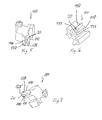
Figur 1 zeigt die Anwendung einer unten auch als "Schablone" angesprochenen erfindungsgemäßen Vorrichtung 10 zur Herstellung einer Fuge aus einer Fugenmasse 12. Die Vorrichtung wird dabei in Richtung des Pfeils 14 entlang einer Fuge bewegt, die in der Zeichnungsebene von links nach rechts verläuft. - Die Vorrichtung 10 besteht aus einem im wesentlichen quaderförmigen Körper, dessen der Fuge zugewandte Kante eine Ausnehmung aufweist, die parallel zu der Kante verläuft, und einen etwa halbkreisförmig nach innen gerichteten Querschnitt aufweist, der parallel zur Fuge entgegen der Richtung des Pfeils 14 verringert wird.
- Raumdiagonal durch den Körper 18 der Vorrichtung 10 verläuft ein Kanal 20, der in einen Gummischlauch 22 mündet, der zur Aufnahme der Spitze 24 einer üblichen Silikon- oder Acryl-Patrone 26 dient.
- Wird nun Fugenmasse aus der Patrone 26 in üblicher Weise ausgepresst, so fließt diese in den Gummischlauch 22 und von dort durch den Kanal 20 in den kantenparallelen Hohlraum 16. An dessen Ende befindet sich eine Kante 28 (in den
Figuren 2 und3 besser erkennbar), die die Oberfläche der entstehenden Fuge formt. -
Figur 2 zeigt eine detailliertere Darstellung der erfindungsgemäßen Vorrichtung 10. Hier ist die Abziehkante 28 zur gleichzeitigen Glättung der Silikonfuge gut zu sehen. Diese ist im dargestellten Ausführungsbeispiel nach außen (auf die Fuge zu) gewölbt. Sie dient der Formung der Fugenoberfläche. - Die
Figuren 2.1 bis 2.6 zeigen die verschiedenen Ansichten der inFigur 2 dargestellten Vorrichtung aus sämtlichen Richtungen. a bezeichnet dabei die jeweilige Fugenbreite in der Ebene und in der Höhe. DieFigur 2.7 zeigt den Schnitt A-A derFigur 2.1 , dieFigur 2.8 zeigt den Schnitt B-B derFigur 2.4 . In dieser Darstellung ist die Verringerung der Tiefe der Ausnehmung 16 deutlich erkennbar. - Die
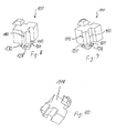
Figuren 3 und 4 zeigen eine weitere Ausführungsform der vorliegenden Erfindung mit einer diagonal verlaufenden Kante 28'. - Die
Figuren 5 bis 10 zeigen dreidimensionale Darstellungen einer weiteren erfindungsgemäßen Vorrichtung, die im Gegensatz zu der vorbeschriebenen Vorrichtung auch bei Fugen anwendbar ist, die von nicht rechtwinklig aufeinander stehenden Flächen begrenzt werden, da die entsprechende Vorrichtung lediglich entlang einer jeweiligen Kante 110 auf den die Fuge begrenzenden Flächen aufliegt. Weiter wird durch die Kanten 110 eine klare Abgrenzung der Fuge erzeugt und die neben den Kanten 110, nämlich außerhalb der Kanten 110 in Bewegungsrichtung am Ende der Vorrichtung angeordneten Abstreifer 130 mit einer jeweiligen Abstreiferkante 131 können dann dennoch seitlich entlang der Kanten 110 ausgetretenes Fugenmaterial entfernen, so dass mit der bevorzugten Ausführungsform der erfindungsgemäßen Vorrichtung auch dann saubere Fugen hergestellt werden können, wenn die zu verfugenden Flächen nicht genau rechtwinklig aufeinander stehen oder Unebenheiten aufweisen. Die Vorrichtung ist dabei um eine raumdiagonale Fläche spiegelsymmetrisch ausgebildet, wobei die eine raumdiagonale Hälfte einen geraden Fugenabschluss mit einer geraden Kante 128 aufweist, während die andere raumdiagonale Hälfte einen konvex gewölbten Abschluss für nach innen gewölbte Fugen mit einer kreissektorförmigen Kante 128' aufweist. Die Zuführöffnung 20 für die Zuführung des Fugenmaterials erstreckt sich dabei ebenfalls raumdiagonal durch die erfindungsgemäße Vorrichtung 100, so dass durch umgekehrtes Aufstecken der Vorrichtung auf die Silikon- oder Acrylspritze jeweils die entgegengesetzten Hälften der raumdiagonal spiegelbildlich aufgebauten Vorrichtung 100 aktiviert werden und entweder nach innen gewölbte oder glatte Fugen hergestellt werden können. - Um die erfindungsgemäße Vorrichtung 100' noch besser in Spritzgussverfahren herstellen zu können, ist die Ausführungsform gemäß
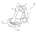
Figuren 11 und12 entwickelt worden. Hierbei ist die Materialdicke der erfindungsgemäßen Vorrichtung nahezu überall gleich, so dass keine Materialanhäufungen entstehen, die beim Spritzgießen Probleme machen könnten. - Die Ausführungsform gemäß den
Figuren 11 und12 erfüllt die Funktionen der Ausführungsform derFiguren 5 bis 10 durch entsprechende Kanten oder ein entsprechendes der Fuge zugewandtes Element und soll im Folgenden unter Verwendung eines eigenen Satzes von Bezugszeichen noch einmal detailliert beschrieben werden: -
Figur 11 zeigt die Anwendung einer erfindungsgemäßen Vorrichtung 100' zur Herstellung einer Fuge aus einer Fugenmasse 12. Die Vorrichtung wird dabei in Richtung des Pfeils 16 entlang einer Fuge bewegt, die in der Zeichnungsebene von links unten nach rechts oben verläuft. - Die Vorrichtung umfasst einen Ausnehmungen oder Aussparungen aufweisenden Körper 25, durch den raumdiagonal ein Kanal 15 verläuft, welcher zur Aufnahme der Spritze 18 einer üblichen Silikon- oder AcrylPatrone oder dergleichen 19 dient, und in einen zur Fuge hin offenen, sich parallel zu dieser erstreckenden Kanal 14 bzw. 20 mündet, welcher an einem Ende durch ein Element begrenzt ist, welches eine die Fuge formende Kante oder Begrenzungsfläche aufweist. Dieser Kanal 14 bzw. 20 gehört zu einem vor dem Element angeordneten, von dem Körper 25 und den zu verfugenden Bauteilen umschlossenen Raum und wird wie bei der vorangehend beschriebenen Ausführungsform durch Widerlagerkanten begrenzt, die parallel zur Fuge verlaufen.
- Wird nun Fugenmasse 12 aus der Patrone 19 in üblicher Weise ausgepresst, so fließt diese in den Kanal 15 und von dort in den Kanal 14 bzw. 20 und damit in den kantenparallelen Hohlraum, an dessen Ende sich die angesprochene, in den Figuren mit 9 bzw. 24 bezeichnete Kante befindet, die die Oberfläche der entstehenden Fuge formt.
- Unter Verwendung der in
Figuren 11 und12 eingetragenen Bezugszeichen kann die dargestellte Ausführungsform einer Vorrichtung 100' zur Herstellung von Fugen zwischen im Winkel aufeinander stoßenden Bauteilen durch Entlangführen der Vorrichtung an den Bauteilen in einer Richtung 16 und deren praktische Verwendung weiter wie folgt beschrieben werden. Durch den Kanal 15 des Körpers 25 der Vorrichtung wird Fugenmasse zugeführt, die in den zur Fuge hin offenen Kanal 14 bzw. Kanal 20 des Körpers und hierüber in den Bereich, in dem die Fuge herzustellen ist, austritt. - Der Körper wird so zwischen den Bauteilen positioniert, dass entweder der Kanal 14 auf der einen Seite des Körpers oder der Kanal 20 auf einer anderen Seite des Körpers dem Winkelbereich zwischen den Bauteilen zugewandt ist, je nachdem, welche Form die Fuge im Querschnitt haben soll. Bei dem Ausführungsbeispiel lässt sich die Fuge mit einer dreieckigen Form oder alternativ mit einer gewölbt konvex verlaufenden Form herstellen, wofür das die Fugenoberfläche definierende und glättende Teil entsprechend geformt ist, nämlich das Teil 11 bzw. das Teil 23 des Körpers.
- Wird nun Fugenmasse über den Kanal 15 und den Kanal 14 bzw. 20 zugeführt und gleichzeitig der Körper 25 in der Richtung des Pfeils 16 bewegt, so wird mit Hilfe des Teils 26 bzw. 27 die außerhalb des Sollbereichs für die Fugenmasse liegende Fugenmasse mitgenommen und ggf. verteilt und in den Sollbereich für die Fugenmasse gedrückt. Das Teil 9 bzw. 24 am Ende des Kanals 14 bzw. 20 gibt der Fuge die richtige Form. Dabei wird die Fuge mit Hilfe des Teils 11 bzw. 23 geglättet, wobei dessen Kante 17 bzw. 3 die Oberfläche der entstehenden Fuge definiert und die richtige Form verleiht, beim Ausführungsbeispiel geradlinig zwischen den Widerlagern für einen dreieckigen Fugenquerschnitt oder zur Fuge hin gewölbt konvex für einen entsprechenden Fugenquerschnitt.
- Die Bezugszeichen 4, 5, 7, 8, 21, 22 sind Elementen des Körpers zugeordnet, die eine Widerlagerfunktion und eventuell auch eine Abstreiferfunktion erfüllen und mit denen der Körper an die Oberflächen der Bauteile angelehnt wird. Es resultiert so ein geschlossener, den Kanal 14 bzw. 20 umfassender Raum, um ein seitliches Auslaufen der Fugenmasse zu verhindern. Sollte trotzdem Fugenmasse auslaufen, so wird überflüssige Fugenmasse durch ebenfalls eine Widerlagerfunktion und zusätzlich eine Abstreiferfunktion erfüllende Elemente 6, 13, 1 und 2 entfernt, welche vorzugsweise zumindest teilweise mit Abstreiferkanten ausgeführt sind.
- Schließlich können die von der Fuge aus betrachtet äußere Seite der Kanten 28, 128, 128', 11, 23 oder/und die äußeren Seiten der Kanten 110, 110', 7, 8, 21, 22 der vorliegenden Erfindung vorzugsweise mit einem dünnen anfeuchtbaren Schwamm beschichtet sein, durch den zusätzlich ein Herumkriechen der Fugenmasse um die Kanten und ein Festsetzen der Fugenmasse auf der Außenseite der Kanten verhindert werden kann.
- Diese Erfindung kann in allen Bereichen eingesetzt werden, wo Silikon, Acryl, Klebstoff verwendet wird, vor allem in der Bau-, Metall-, Autoindustrie.
- Jetzt aktuell verwendete Schablonen haben eine Menge Mängel:
- Einen großen Verlust von Material,
- Verschwendung von Zeit,
- Umweltverschmutzung,
- ungleichmäßige Dicke der Fugen,
- nur professionelle Mitarbeiter können mit diesen Schablonen arbeiten.
- Mit dieser Erfindung wird gelöst:
- Materialausnutzung 99 %,
- Hochgeschwindigkeit der Arbeiten,
- es kann von Amateuren und Profis verwendet werden,
- die Fugen sind gerade und gleich dick,
- große Einsparung der Materialien,
- Umweltschutz.
- Die Schablone ist sehr klein, Minimum 10 mm x 10 mm x 10 mm,
- Verschiedene Länge des Gummischlauchs, kommt leicht an unzugängliche Stellen,
- eine Schablone für alle Richtungen.
- Die Systembedienung ist sehr einfach. Auf der einen Seite wird die Schablone gehalten und auf der anderen eine Silikonspritze. Das Silikon läuft durch den Gummischlauch und durch die Schablone in die konische Öffnung im unteren Bereich der Schablone.
- Wenn zu sehen ist, dass das Silikon die konische Öffnung ausgefüllt hat, wird die Schablone in die gewünschte Richtung bewegt.
- Die Schablone muss nach vorne bewegt werden, bevor das Material austritt, so bleibt die gewünschte Form erhalten.
- Im Fall, dass das Material austritt, kann es mit der Schablone entfernt werden.
- Schablonen können aus verschiedenen Formen und verschiedenen Materialien sein.
- Der Gummischlauch dreht sich um die eigene Achse.
- Der konische Abschnitt der Schablone ermöglicht die leichte Bewegung des Materials nach vorne in die Richtung, in die sich die Schablone bewegt.
- Schablonen können sich von rechts nach links, von links nach rechts, von unten nach oben, und von oben nach unten bewegen.
Claims (9)
- Vorrichtung (10; 10'; 100; 100') zur Herstellung von Fugen zwischen im Winkel aufeinander stoßenden Bauteilen durch Entlangführen der Vorrichtung an den Bauteilen in einer Richtung (14), gekennzeichnet durch einen Körper (18; 18'; 118; 25), der ein Element mit einer der Fuge zugewandten Kante (28; 128; 128'; 11; 23) zum Formen der Fuge, welches an beiden Seiten von Widerlagern umgeben ist, umfasst, die sich jeweils auf einem der Bauteile abstützen, und einen Kanal (20) umfasst, der in einen in der Richtung (14) vor dem Element angeordneten Raum (16) mündet, der von dem Körper (18; 18'; 118; 25) und den Bauteilen umschlossen wird, und dessen anderes Ende (22) zur Aufnahme einer Anschlussvorrichtung eines Behälters (26) mit Fugenmasse ausgebildet ist.
- Vorrichtung nach Anspruch 1, dadurch gekennzeichnet, dass der Körper (18) als Quader ausgebildet ist, und die Widerlager durch zwei benachbarte Flächen des Quaders gebildet sind.
- Vorrichtung (10) nach Anspruch 1 oder 2, dadurch gekennzeichnet, dass die Widerlager zwei parallel zur Fuge verlaufende Kanten auf beiden Seiten der Fuge oder/und zwei unter einem Winkel, vorzugsweise orthogonal zur Fuge verlaufende Kanten auf beiden Seiten der Fuge umfassen.
- Vorrichtung (10) nach einem der Ansprüche 1 bis 3, dadurch gekennzeichnet, dass der Raum (16) einen diagonal angeschnittenen, runden, ovalen oder mehreckigen, beispielsweise quadratischen Querschnitt senkrecht zu der Richtung (14) aufweist.
- Vorrichtung (10) nach Anspruch 4, dadurch gekennzeichnet, dass der Raum (16) zusätzlich dergestalt konisch ausgebildet ist, dass sein Durchmesser auf das Element hin abnimmt.
- Vorrichtung (10) nach einem der Ansprüche 1 bis 5, dadurch gekennzeichnet, dass die der Fuge zugewandte Kante (28) des Elements gerade zwischen den Widerlagern verläuft.
- Vorrichtung (10) nach einem der Ansprüche 1 bis 6, dadurch gekennzeichnet, dass die der Fuge zugewandte Kante (28) des Elements zur Fuge hin gewölbt konvex verläuft.
- Vorrichtung nach einem der vorhergehenden Ansprüche 1 bis 7, dadurch gekennzeichnet, dass der Körper (25) derart elastisch verformbar ist, dass die Widerlager sich an einen von einem Normwinkel abweichenden Winkel zwischen den aufeinander stoßenden Bauteilen anpassen können.
- Vorrichtung nach einem der vorhergehenden Ansprüche 1 bis 8, gekennzeichnet durch wenigstens ein anfeuchtbares Schwammelement auf einer an einer Widerlagerkante oder Widerlagerfläche angrenzenden Außenseite des Körpers.
Applications Claiming Priority (1)
| Application Number | Priority Date | Filing Date | Title |
|---|---|---|---|
| DE202014003184.3U DE202014003184U1 (de) | 2014-04-14 | 2014-04-14 | Vorrichtung zur Herstellung von Fugen zwischen im Winkel aufeinander stoßenden Bauteilen |
Publications (2)
| Publication Number | Publication Date |
|---|---|
| EP2942109A1 true EP2942109A1 (de) | 2015-11-11 |
| EP2942109B1 EP2942109B1 (de) | 2019-12-11 |
Family
ID=52009305
Family Applications (1)
| Application Number | Title | Priority Date | Filing Date |
|---|---|---|---|
| EP15163528.1A Active EP2942109B1 (de) | 2014-04-14 | 2015-04-14 | Vorrichtung zur herstellung von fugen zwischen im winkel aufeinander stossenden bauteilen |
Country Status (2)
| Country | Link |
|---|---|
| EP (1) | EP2942109B1 (de) |
| DE (1) | DE202014003184U1 (de) |
Cited By (4)
| Publication number | Priority date | Publication date | Assignee | Title |
|---|---|---|---|---|
| CN111036491A (zh) * | 2018-10-11 | 2020-04-21 | 株式会社斯巴鲁 | 密封材料喷出喷嘴和密封材料喷出装置 |
| CN111036490A (zh) * | 2018-10-11 | 2020-04-21 | 株式会社斯巴鲁 | 密封材料喷出喷嘴和密封材料喷出装置 |
| WO2022171245A1 (de) * | 2021-02-11 | 2022-08-18 | Bernd Kowalewski | Auftragsdüse mit einem elastischen ausformbereich zum manuellen auftragen eines dimensionierten pastenförmigen dichtungsmittelstrangs für eine eckfugenabdichtung |
| US11426755B2 (en) * | 2018-10-11 | 2022-08-30 | Subaru Corporation | Sealant discharging nozzle and sealant discharging apparatus |
Citations (5)
| Publication number | Priority date | Publication date | Assignee | Title |
|---|---|---|---|---|
| US3559234A (en) * | 1969-01-08 | 1971-02-02 | Dow Corning | Corner tool and applicator nozzle |
| DE7812552U1 (de) * | 1978-04-19 | 1978-09-14 | Zern Klaus | Vorrichtung zum Ein- und Aufbringen von verschiedenen Materialien aus Kartuschen o dgl |
| US5622728A (en) * | 1993-09-08 | 1997-04-22 | Thomas P. Mahoney | Wiping device for caulking, and method of forming same |
| EP1522654A2 (de) * | 2003-10-08 | 2005-04-13 | Christian Hoffmann | Werkzeug zum Ausfugen von Fugen |
| DE202013003380U1 (de) * | 2013-04-11 | 2013-05-31 | Hasan Balci | Spritztülle für plastische Verfugungsmassen |
-
2014
- 2014-04-14 DE DE202014003184.3U patent/DE202014003184U1/de not_active Expired - Lifetime
-
2015
- 2015-04-14 EP EP15163528.1A patent/EP2942109B1/de active Active
Patent Citations (5)
| Publication number | Priority date | Publication date | Assignee | Title |
|---|---|---|---|---|
| US3559234A (en) * | 1969-01-08 | 1971-02-02 | Dow Corning | Corner tool and applicator nozzle |
| DE7812552U1 (de) * | 1978-04-19 | 1978-09-14 | Zern Klaus | Vorrichtung zum Ein- und Aufbringen von verschiedenen Materialien aus Kartuschen o dgl |
| US5622728A (en) * | 1993-09-08 | 1997-04-22 | Thomas P. Mahoney | Wiping device for caulking, and method of forming same |
| EP1522654A2 (de) * | 2003-10-08 | 2005-04-13 | Christian Hoffmann | Werkzeug zum Ausfugen von Fugen |
| DE202013003380U1 (de) * | 2013-04-11 | 2013-05-31 | Hasan Balci | Spritztülle für plastische Verfugungsmassen |
Cited By (7)
| Publication number | Priority date | Publication date | Assignee | Title |
|---|---|---|---|---|
| CN111036491A (zh) * | 2018-10-11 | 2020-04-21 | 株式会社斯巴鲁 | 密封材料喷出喷嘴和密封材料喷出装置 |
| CN111036490A (zh) * | 2018-10-11 | 2020-04-21 | 株式会社斯巴鲁 | 密封材料喷出喷嘴和密封材料喷出装置 |
| US11325150B2 (en) * | 2018-10-11 | 2022-05-10 | Subaru Corporation | Sealant discharging nozzle and sealant discharging apparatus |
| CN111036491B (zh) * | 2018-10-11 | 2022-06-24 | 株式会社斯巴鲁 | 密封材料喷出喷嘴和密封材料喷出装置 |
| US11426755B2 (en) * | 2018-10-11 | 2022-08-30 | Subaru Corporation | Sealant discharging nozzle and sealant discharging apparatus |
| CN111036490B (zh) * | 2018-10-11 | 2023-01-06 | 株式会社斯巴鲁 | 密封材料喷出喷嘴和密封材料喷出装置 |
| WO2022171245A1 (de) * | 2021-02-11 | 2022-08-18 | Bernd Kowalewski | Auftragsdüse mit einem elastischen ausformbereich zum manuellen auftragen eines dimensionierten pastenförmigen dichtungsmittelstrangs für eine eckfugenabdichtung |
Also Published As
| Publication number | Publication date |
|---|---|
| EP2942109B1 (de) | 2019-12-11 |
| DE202014003184U1 (de) | 2014-11-05 |
Similar Documents
| Publication | Publication Date | Title |
|---|---|---|
| EP2942109B1 (de) | Vorrichtung zur herstellung von fugen zwischen im winkel aufeinander stossenden bauteilen | |
| DE2426322A1 (de) | Spachtel | |
| EP3255222B1 (de) | Vorrichtung und system zum verarbeiten einer fugenmasse | |
| DE202014001032U1 (de) | Düse zum Applizieren pastöser Stoffe | |
| AT407063B (de) | Verfahren zum abdichten von spundbohlenkonstruktionen und vorrichtung zur herstellung einer abdichtung in einer klauenkammer einer spundbohle | |
| DE2348607C2 (de) | Thermoschweißverfahren zum stirnseitigen Verbinden zweier Kunststoffwände | |
| EP2363564B1 (de) | Klebedüse zur Verwendung beim Verkleben einer Scheibenanordnung mit einem Profil für Fenster und Türen | |
| DE2809283C2 (de) | Vorrichtung zum Beschichten von Bleistiften | |
| DE102018122840A1 (de) | Vorrichtung zum Verarbeiten von Kleb- und Dichtstoffen | |
| EP1666683B1 (de) | Werkzeug zum Nachbearbeiten und Glätten plastischer Fugenmasse | |
| DE202021105473U1 (de) | Düse, Düsenanordnung und Vorrichtung zum Einbringen eines pastösen Mediums in eine Gehrungsfuge | |
| AT406979B (de) | Verfahren zum auftragen eines thermoplastischen abstandhalters auf eine glasscheibe im zuge der herstellung von isolierglasscheiben und zum durchführen des verfahrens verwendbare düse | |
| DE202022106552U1 (de) | Werkzeug zum Nacharbeiten und Glätten von Fugen | |
| DE102021103767A1 (de) | Fugenziehaufsatz, Fugenkartusche und Verfahren hierzu | |
| DE202022106549U1 (de) | Werkzeug zum Nacharbeiten und Glätten von Fugen | |
| DE102010045992A1 (de) | Verfugungswerkzeug | |
| DE10351388B4 (de) | Flexibles Dichtmassen abweisendes Werkzeug | |
| DE9108560U1 (de) | Werkzeug zum Einbringen von Hinterfüllungsmaterial in eine Fuge | |
| DE29603258U1 (de) | Metallprofil für die Bildung von Rahmenwerken mit Eckverbindungen | |
| DE202022000314U1 (de) | Auftragsdüse mit einem elastischen Ausformbereich zum manuellen Auftragen eines dimensionierten pastenförmigen Dichtungsmittelstrangs für eine Eckfugenabdichtung | |
| DE8124555U1 (de) | Streicheinsatz | |
| DE2000687C (de) | Vorrichtung zum Auftragen einer fließfähigen Masse | |
| DE102013004868B4 (de) | Dosiernadel | |
| DE202008012507U1 (de) | Vorrichtung zum Einbringen von Spachtelmaterial in Fugen | |
| EP1522654A2 (de) | Werkzeug zum Ausfugen von Fugen |
Legal Events
| Date | Code | Title | Description |
|---|---|---|---|
| PUAI | Public reference made under article 153(3) epc to a published international application that has entered the european phase |
Free format text: ORIGINAL CODE: 0009012 |
|
| AK | Designated contracting states |
Kind code of ref document: A1 Designated state(s): AL AT BE BG CH CY CZ DE DK EE ES FI FR GB GR HR HU IE IS IT LI LT LU LV MC MK MT NL NO PL PT RO RS SE SI SK SM TR |
|
| AX | Request for extension of the european patent |
Extension state: BA ME |
|
| 17P | Request for examination filed |
Effective date: 20160504 |
|
| RBV | Designated contracting states (corrected) |
Designated state(s): AL AT BE BG CH CY CZ DE DK EE ES FI FR GB GR HR HU IE IS IT LI LT LU LV MC MK MT NL NO PL PT RO RS SE SI SK SM TR |
|
| GRAP | Despatch of communication of intention to grant a patent |
Free format text: ORIGINAL CODE: EPIDOSNIGR1 |
|
| STAA | Information on the status of an ep patent application or granted ep patent |
Free format text: STATUS: GRANT OF PATENT IS INTENDED |
|
| RIC1 | Information provided on ipc code assigned before grant |
Ipc: B05C 17/005 20060101AFI20190503BHEP Ipc: B05C 17/10 20060101ALN20190503BHEP |
|
| INTG | Intention to grant announced |
Effective date: 20190529 |
|
| GRAS | Grant fee paid |
Free format text: ORIGINAL CODE: EPIDOSNIGR3 |
|
| GRAA | (expected) grant |
Free format text: ORIGINAL CODE: 0009210 |
|
| STAA | Information on the status of an ep patent application or granted ep patent |
Free format text: STATUS: THE PATENT HAS BEEN GRANTED |
|
| AK | Designated contracting states |
Kind code of ref document: B1 Designated state(s): AL AT BE BG CH CY CZ DE DK EE ES FI FR GB GR HR HU IE IS IT LI LT LU LV MC MK MT NL NO PL PT RO RS SE SI SK SM TR |
|
| REG | Reference to a national code |
Ref country code: GB Ref legal event code: FG4D Free format text: NOT ENGLISH |
|
| REG | Reference to a national code |
Ref country code: CH Ref legal event code: EP |
|
| REG | Reference to a national code |
Ref country code: AT Ref legal event code: REF Ref document number: 1211672 Country of ref document: AT Kind code of ref document: T Effective date: 20191215 |
|
| REG | Reference to a national code |
Ref country code: DE Ref legal event code: R096 Ref document number: 502015011172 Country of ref document: DE |
|
| REG | Reference to a national code |
Ref country code: IE Ref legal event code: FG4D Free format text: LANGUAGE OF EP DOCUMENT: GERMAN |
|
| REG | Reference to a national code |
Ref country code: NL Ref legal event code: MP Effective date: 20191211 |
|
| REG | Reference to a national code |
Ref country code: LT Ref legal event code: MG4D |
|
| PG25 | Lapsed in a contracting state [announced via postgrant information from national office to epo] |
Ref country code: LV Free format text: LAPSE BECAUSE OF FAILURE TO SUBMIT A TRANSLATION OF THE DESCRIPTION OR TO PAY THE FEE WITHIN THE PRESCRIBED TIME-LIMIT Effective date: 20191211 Ref country code: SE Free format text: LAPSE BECAUSE OF FAILURE TO SUBMIT A TRANSLATION OF THE DESCRIPTION OR TO PAY THE FEE WITHIN THE PRESCRIBED TIME-LIMIT Effective date: 20191211 Ref country code: NO Free format text: LAPSE BECAUSE OF FAILURE TO SUBMIT A TRANSLATION OF THE DESCRIPTION OR TO PAY THE FEE WITHIN THE PRESCRIBED TIME-LIMIT Effective date: 20200311 Ref country code: GR Free format text: LAPSE BECAUSE OF FAILURE TO SUBMIT A TRANSLATION OF THE DESCRIPTION OR TO PAY THE FEE WITHIN THE PRESCRIBED TIME-LIMIT Effective date: 20200312 Ref country code: LT Free format text: LAPSE BECAUSE OF FAILURE TO SUBMIT A TRANSLATION OF THE DESCRIPTION OR TO PAY THE FEE WITHIN THE PRESCRIBED TIME-LIMIT Effective date: 20191211 Ref country code: BG Free format text: LAPSE BECAUSE OF FAILURE TO SUBMIT A TRANSLATION OF THE DESCRIPTION OR TO PAY THE FEE WITHIN THE PRESCRIBED TIME-LIMIT Effective date: 20200311 Ref country code: FI Free format text: LAPSE BECAUSE OF FAILURE TO SUBMIT A TRANSLATION OF THE DESCRIPTION OR TO PAY THE FEE WITHIN THE PRESCRIBED TIME-LIMIT Effective date: 20191211 |
|
| PG25 | Lapsed in a contracting state [announced via postgrant information from national office to epo] |
Ref country code: RS Free format text: LAPSE BECAUSE OF FAILURE TO SUBMIT A TRANSLATION OF THE DESCRIPTION OR TO PAY THE FEE WITHIN THE PRESCRIBED TIME-LIMIT Effective date: 20191211 Ref country code: HR Free format text: LAPSE BECAUSE OF FAILURE TO SUBMIT A TRANSLATION OF THE DESCRIPTION OR TO PAY THE FEE WITHIN THE PRESCRIBED TIME-LIMIT Effective date: 20191211 |
|
| PG25 | Lapsed in a contracting state [announced via postgrant information from national office to epo] |
Ref country code: AL Free format text: LAPSE BECAUSE OF FAILURE TO SUBMIT A TRANSLATION OF THE DESCRIPTION OR TO PAY THE FEE WITHIN THE PRESCRIBED TIME-LIMIT Effective date: 20191211 |
|
| PG25 | Lapsed in a contracting state [announced via postgrant information from national office to epo] |
Ref country code: PT Free format text: LAPSE BECAUSE OF FAILURE TO SUBMIT A TRANSLATION OF THE DESCRIPTION OR TO PAY THE FEE WITHIN THE PRESCRIBED TIME-LIMIT Effective date: 20200506 Ref country code: EE Free format text: LAPSE BECAUSE OF FAILURE TO SUBMIT A TRANSLATION OF THE DESCRIPTION OR TO PAY THE FEE WITHIN THE PRESCRIBED TIME-LIMIT Effective date: 20191211 Ref country code: RO Free format text: LAPSE BECAUSE OF FAILURE TO SUBMIT A TRANSLATION OF THE DESCRIPTION OR TO PAY THE FEE WITHIN THE PRESCRIBED TIME-LIMIT Effective date: 20191211 Ref country code: CZ Free format text: LAPSE BECAUSE OF FAILURE TO SUBMIT A TRANSLATION OF THE DESCRIPTION OR TO PAY THE FEE WITHIN THE PRESCRIBED TIME-LIMIT Effective date: 20191211 Ref country code: NL Free format text: LAPSE BECAUSE OF FAILURE TO SUBMIT A TRANSLATION OF THE DESCRIPTION OR TO PAY THE FEE WITHIN THE PRESCRIBED TIME-LIMIT Effective date: 20191211 Ref country code: ES Free format text: LAPSE BECAUSE OF FAILURE TO SUBMIT A TRANSLATION OF THE DESCRIPTION OR TO PAY THE FEE WITHIN THE PRESCRIBED TIME-LIMIT Effective date: 20191211 |
|
| PG25 | Lapsed in a contracting state [announced via postgrant information from national office to epo] |
Ref country code: SM Free format text: LAPSE BECAUSE OF FAILURE TO SUBMIT A TRANSLATION OF THE DESCRIPTION OR TO PAY THE FEE WITHIN THE PRESCRIBED TIME-LIMIT Effective date: 20191211 Ref country code: SK Free format text: LAPSE BECAUSE OF FAILURE TO SUBMIT A TRANSLATION OF THE DESCRIPTION OR TO PAY THE FEE WITHIN THE PRESCRIBED TIME-LIMIT Effective date: 20191211 Ref country code: IS Free format text: LAPSE BECAUSE OF FAILURE TO SUBMIT A TRANSLATION OF THE DESCRIPTION OR TO PAY THE FEE WITHIN THE PRESCRIBED TIME-LIMIT Effective date: 20200411 |
|
| REG | Reference to a national code |
Ref country code: DE Ref legal event code: R097 Ref document number: 502015011172 Country of ref document: DE |
|
| PLBE | No opposition filed within time limit |
Free format text: ORIGINAL CODE: 0009261 |
|
| STAA | Information on the status of an ep patent application or granted ep patent |
Free format text: STATUS: NO OPPOSITION FILED WITHIN TIME LIMIT |
|
| PG25 | Lapsed in a contracting state [announced via postgrant information from national office to epo] |
Ref country code: DK Free format text: LAPSE BECAUSE OF FAILURE TO SUBMIT A TRANSLATION OF THE DESCRIPTION OR TO PAY THE FEE WITHIN THE PRESCRIBED TIME-LIMIT Effective date: 20191211 |
|
| 26N | No opposition filed |
Effective date: 20200914 |
|
| PG25 | Lapsed in a contracting state [announced via postgrant information from national office to epo] |
Ref country code: SI Free format text: LAPSE BECAUSE OF FAILURE TO SUBMIT A TRANSLATION OF THE DESCRIPTION OR TO PAY THE FEE WITHIN THE PRESCRIBED TIME-LIMIT Effective date: 20191211 Ref country code: MC Free format text: LAPSE BECAUSE OF FAILURE TO SUBMIT A TRANSLATION OF THE DESCRIPTION OR TO PAY THE FEE WITHIN THE PRESCRIBED TIME-LIMIT Effective date: 20191211 |
|
| REG | Reference to a national code |
Ref country code: CH Ref legal event code: PL |
|
| PG25 | Lapsed in a contracting state [announced via postgrant information from national office to epo] |
Ref country code: FR Free format text: LAPSE BECAUSE OF NON-PAYMENT OF DUE FEES Effective date: 20200430 Ref country code: LU Free format text: LAPSE BECAUSE OF NON-PAYMENT OF DUE FEES Effective date: 20200414 Ref country code: IT Free format text: LAPSE BECAUSE OF FAILURE TO SUBMIT A TRANSLATION OF THE DESCRIPTION OR TO PAY THE FEE WITHIN THE PRESCRIBED TIME-LIMIT Effective date: 20191211 Ref country code: LI Free format text: LAPSE BECAUSE OF NON-PAYMENT OF DUE FEES Effective date: 20200430 Ref country code: CH Free format text: LAPSE BECAUSE OF NON-PAYMENT OF DUE FEES Effective date: 20200430 |
|
| REG | Reference to a national code |
Ref country code: BE Ref legal event code: MM Effective date: 20200430 |
|
| PG25 | Lapsed in a contracting state [announced via postgrant information from national office to epo] |
Ref country code: PL Free format text: LAPSE BECAUSE OF FAILURE TO SUBMIT A TRANSLATION OF THE DESCRIPTION OR TO PAY THE FEE WITHIN THE PRESCRIBED TIME-LIMIT Effective date: 20191211 Ref country code: BE Free format text: LAPSE BECAUSE OF NON-PAYMENT OF DUE FEES Effective date: 20200430 |
|
| GBPC | Gb: european patent ceased through non-payment of renewal fee |
Effective date: 20200414 |
|
| PG25 | Lapsed in a contracting state [announced via postgrant information from national office to epo] |
Ref country code: IE Free format text: LAPSE BECAUSE OF NON-PAYMENT OF DUE FEES Effective date: 20200414 Ref country code: GB Free format text: LAPSE BECAUSE OF NON-PAYMENT OF DUE FEES Effective date: 20200414 |
|
| REG | Reference to a national code |
Ref country code: AT Ref legal event code: MM01 Ref document number: 1211672 Country of ref document: AT Kind code of ref document: T Effective date: 20200414 |
|
| PG25 | Lapsed in a contracting state [announced via postgrant information from national office to epo] |
Ref country code: AT Free format text: LAPSE BECAUSE OF NON-PAYMENT OF DUE FEES Effective date: 20200414 |
|
| PG25 | Lapsed in a contracting state [announced via postgrant information from national office to epo] |
Ref country code: TR Free format text: LAPSE BECAUSE OF FAILURE TO SUBMIT A TRANSLATION OF THE DESCRIPTION OR TO PAY THE FEE WITHIN THE PRESCRIBED TIME-LIMIT Effective date: 20191211 Ref country code: MT Free format text: LAPSE BECAUSE OF FAILURE TO SUBMIT A TRANSLATION OF THE DESCRIPTION OR TO PAY THE FEE WITHIN THE PRESCRIBED TIME-LIMIT Effective date: 20191211 Ref country code: CY Free format text: LAPSE BECAUSE OF FAILURE TO SUBMIT A TRANSLATION OF THE DESCRIPTION OR TO PAY THE FEE WITHIN THE PRESCRIBED TIME-LIMIT Effective date: 20191211 |
|
| PG25 | Lapsed in a contracting state [announced via postgrant information from national office to epo] |
Ref country code: MK Free format text: LAPSE BECAUSE OF FAILURE TO SUBMIT A TRANSLATION OF THE DESCRIPTION OR TO PAY THE FEE WITHIN THE PRESCRIBED TIME-LIMIT Effective date: 20191211 |
|
| PGFP | Annual fee paid to national office [announced via postgrant information from national office to epo] |
Ref country code: DE Payment date: 20220426 Year of fee payment: 8 |
|
| REG | Reference to a national code |
Ref country code: DE Ref legal event code: R119 Ref document number: 502015011172 Country of ref document: DE |
|
| PG25 | Lapsed in a contracting state [announced via postgrant information from national office to epo] |
Ref country code: DE Free format text: LAPSE BECAUSE OF NON-PAYMENT OF DUE FEES Effective date: 20231103 |