EP2940773A1 - Auswerfer für Festoxid-Elektrolysezellenstapelsystem - Google Patents
Auswerfer für Festoxid-Elektrolysezellenstapelsystem Download PDFInfo
- Publication number
- EP2940773A1 EP2940773A1 EP14166323.7A EP14166323A EP2940773A1 EP 2940773 A1 EP2940773 A1 EP 2940773A1 EP 14166323 A EP14166323 A EP 14166323A EP 2940773 A1 EP2940773 A1 EP 2940773A1
- Authority
- EP
- European Patent Office
- Prior art keywords
- soec
- stack
- gas
- process gas
- process according
- Prior art date
- Legal status (The legal status is an assumption and is not a legal conclusion. Google has not performed a legal analysis and makes no representation as to the accuracy of the status listed.)
- Withdrawn
Links
- 238000005868 electrolysis reaction Methods 0.000 title claims abstract description 30
- 239000007787 solid Substances 0.000 title claims abstract description 21
- 239000007789 gas Substances 0.000 claims abstract description 146
- CURLTUGMZLYLDI-UHFFFAOYSA-N Carbon dioxide Chemical compound O=C=O CURLTUGMZLYLDI-UHFFFAOYSA-N 0.000 claims abstract description 116
- 238000000034 method Methods 0.000 claims abstract description 105
- 229910002092 carbon dioxide Inorganic materials 0.000 claims abstract description 86
- 239000001569 carbon dioxide Substances 0.000 claims abstract description 85
- UGFAIRIUMAVXCW-UHFFFAOYSA-N Carbon monoxide Chemical compound [O+]#[C-] UGFAIRIUMAVXCW-UHFFFAOYSA-N 0.000 claims abstract description 83
- 229910002091 carbon monoxide Inorganic materials 0.000 claims abstract description 83
- 229910052760 oxygen Inorganic materials 0.000 claims description 51
- 239000001301 oxygen Substances 0.000 claims description 51
- QVGXLLKOCUKJST-UHFFFAOYSA-N atomic oxygen Chemical compound [O] QVGXLLKOCUKJST-UHFFFAOYSA-N 0.000 claims description 50
- 239000000446 fuel Substances 0.000 claims description 41
- 238000001179 sorption measurement Methods 0.000 claims description 32
- 238000000926 separation method Methods 0.000 claims description 19
- OKTJSMMVPCPJKN-UHFFFAOYSA-N Carbon Chemical compound [C] OKTJSMMVPCPJKN-UHFFFAOYSA-N 0.000 claims description 18
- 229910052799 carbon Inorganic materials 0.000 claims description 16
- 238000010438 heat treatment Methods 0.000 claims description 16
- 238000000746 purification Methods 0.000 claims description 16
- 229910052751 metal Inorganic materials 0.000 claims description 14
- 239000002184 metal Substances 0.000 claims description 14
- 238000010926 purge Methods 0.000 claims description 14
- 230000015572 biosynthetic process Effects 0.000 claims description 13
- 238000010410 dusting Methods 0.000 claims description 13
- 239000003463 adsorbent Substances 0.000 claims description 11
- 238000001816 cooling Methods 0.000 claims description 8
- 229910052802 copper Inorganic materials 0.000 claims description 8
- CRVGTESFCCXCTH-UHFFFAOYSA-N methyl diethanolamine Chemical compound OCCN(C)CCO CRVGTESFCCXCTH-UHFFFAOYSA-N 0.000 claims description 8
- 239000007788 liquid Substances 0.000 claims description 7
- 238000004064 recycling Methods 0.000 claims description 7
- 229910052759 nickel Inorganic materials 0.000 claims description 6
- 238000011144 upstream manufacturing Methods 0.000 claims description 6
- 230000003197 catalytic effect Effects 0.000 claims description 5
- 238000005516 engineering process Methods 0.000 claims description 5
- 239000012528 membrane Substances 0.000 claims description 5
- PNEYBMLMFCGWSK-UHFFFAOYSA-N aluminium oxide Inorganic materials [O-2].[O-2].[O-2].[Al+3].[Al+3] PNEYBMLMFCGWSK-UHFFFAOYSA-N 0.000 claims description 4
- 239000007800 oxidant agent Substances 0.000 claims description 4
- 230000001419 dependent effect Effects 0.000 claims description 3
- 238000011010 flushing procedure Methods 0.000 claims description 3
- 238000010791 quenching Methods 0.000 claims description 3
- XLOMVQKBTHCTTD-UHFFFAOYSA-N zinc oxide Inorganic materials [Zn]=O XLOMVQKBTHCTTD-UHFFFAOYSA-N 0.000 claims description 3
- 239000002826 coolant Substances 0.000 claims description 2
- 239000011261 inert gas Substances 0.000 claims description 2
- 231100000572 poisoning Toxicity 0.000 claims 1
- 230000000607 poisoning effect Effects 0.000 claims 1
- 239000002912 waste gas Substances 0.000 abstract 1
- 230000003647 oxidation Effects 0.000 description 12
- 238000007254 oxidation reaction Methods 0.000 description 12
- 239000000203 mixture Substances 0.000 description 10
- PXHVJJICTQNCMI-UHFFFAOYSA-N nickel Substances [Ni] PXHVJJICTQNCMI-UHFFFAOYSA-N 0.000 description 9
- 239000003054 catalyst Substances 0.000 description 8
- 239000010949 copper Substances 0.000 description 8
- 238000004519 manufacturing process Methods 0.000 description 8
- XLYOFNOQVPJJNP-UHFFFAOYSA-N water Substances O XLYOFNOQVPJJNP-UHFFFAOYSA-N 0.000 description 8
- IJGRMHOSHXDMSA-UHFFFAOYSA-N Atomic nitrogen Chemical compound N#N IJGRMHOSHXDMSA-UHFFFAOYSA-N 0.000 description 7
- UFHFLCQGNIYNRP-UHFFFAOYSA-N Hydrogen Chemical compound [H][H] UFHFLCQGNIYNRP-UHFFFAOYSA-N 0.000 description 6
- 239000001257 hydrogen Substances 0.000 description 6
- 229910052739 hydrogen Inorganic materials 0.000 description 6
- 239000003570 air Substances 0.000 description 5
- 238000006243 chemical reaction Methods 0.000 description 5
- 239000000463 material Substances 0.000 description 5
- 230000001590 oxidative effect Effects 0.000 description 5
- 238000006722 reduction reaction Methods 0.000 description 5
- 229910052782 aluminium Inorganic materials 0.000 description 4
- -1 aluminium halides Chemical class 0.000 description 4
- 230000006378 damage Effects 0.000 description 4
- VUZPPFZMUPKLLV-UHFFFAOYSA-N methane;hydrate Chemical compound C.O VUZPPFZMUPKLLV-UHFFFAOYSA-N 0.000 description 4
- UHOVQNZJYSORNB-UHFFFAOYSA-N Benzene Chemical compound C1=CC=CC=C1 UHOVQNZJYSORNB-UHFFFAOYSA-N 0.000 description 3
- 238000010744 Boudouard reaction Methods 0.000 description 3
- OKKJLVBELUTLKV-UHFFFAOYSA-N Methanol Chemical compound OC OKKJLVBELUTLKV-UHFFFAOYSA-N 0.000 description 3
- 230000009286 beneficial effect Effects 0.000 description 3
- 238000000354 decomposition reaction Methods 0.000 description 3
- 229910052757 nitrogen Inorganic materials 0.000 description 3
- 239000010457 zeolite Substances 0.000 description 3
- JPVYNHNXODAKFH-UHFFFAOYSA-N Cu2+ Chemical compound [Cu+2] JPVYNHNXODAKFH-UHFFFAOYSA-N 0.000 description 2
- NINIDFKCEFEMDL-UHFFFAOYSA-N Sulfur Chemical compound [S] NINIDFKCEFEMDL-UHFFFAOYSA-N 0.000 description 2
- GWEVSGVZZGPLCZ-UHFFFAOYSA-N Titan oxide Chemical compound O=[Ti]=O GWEVSGVZZGPLCZ-UHFFFAOYSA-N 0.000 description 2
- 239000002250 absorbent Substances 0.000 description 2
- 230000002745 absorbent Effects 0.000 description 2
- 239000004411 aluminium Substances 0.000 description 2
- 230000015556 catabolic process Effects 0.000 description 2
- 238000004140 cleaning Methods 0.000 description 2
- 239000000356 contaminant Substances 0.000 description 2
- 229910001431 copper ion Inorganic materials 0.000 description 2
- 230000007797 corrosion Effects 0.000 description 2
- 238000005260 corrosion Methods 0.000 description 2
- 238000006731 degradation reaction Methods 0.000 description 2
- 230000001747 exhibiting effect Effects 0.000 description 2
- 229930195733 hydrocarbon Natural products 0.000 description 2
- 150000002430 hydrocarbons Chemical class 0.000 description 2
- 239000012535 impurity Substances 0.000 description 2
- 238000002347 injection Methods 0.000 description 2
- 239000007924 injection Substances 0.000 description 2
- 229910052763 palladium Inorganic materials 0.000 description 2
- 229910052697 platinum Inorganic materials 0.000 description 2
- 239000000243 solution Substances 0.000 description 2
- 229910052717 sulfur Inorganic materials 0.000 description 2
- 239000011593 sulfur Substances 0.000 description 2
- 230000008646 thermal stress Effects 0.000 description 2
- 239000011787 zinc oxide Substances 0.000 description 2
- 239000004215 Carbon black (E152) Substances 0.000 description 1
- RYGMFSIKBFXOCR-UHFFFAOYSA-N Copper Chemical compound [Cu] RYGMFSIKBFXOCR-UHFFFAOYSA-N 0.000 description 1
- 239000004793 Polystyrene Substances 0.000 description 1
- XAGFODPZIPBFFR-UHFFFAOYSA-N aluminium Chemical compound [Al] XAGFODPZIPBFFR-UHFFFAOYSA-N 0.000 description 1
- 239000012080 ambient air Substances 0.000 description 1
- 229910021525 ceramic electrolyte Inorganic materials 0.000 description 1
- 239000011248 coating agent Substances 0.000 description 1
- 238000000576 coating method Methods 0.000 description 1
- 238000002485 combustion reaction Methods 0.000 description 1
- 150000001875 compounds Chemical class 0.000 description 1
- 238000009833 condensation Methods 0.000 description 1
- 230000005494 condensation Effects 0.000 description 1
- 238000010924 continuous production Methods 0.000 description 1
- 239000011258 core-shell material Substances 0.000 description 1
- 230000007423 decrease Effects 0.000 description 1
- 230000002950 deficient Effects 0.000 description 1
- 230000001627 detrimental effect Effects 0.000 description 1
- HNPSIPDUKPIQMN-UHFFFAOYSA-N dioxosilane;oxo(oxoalumanyloxy)alumane Chemical compound O=[Si]=O.O=[Al]O[Al]=O HNPSIPDUKPIQMN-UHFFFAOYSA-N 0.000 description 1
- 238000009826 distribution Methods 0.000 description 1
- 238000011143 downstream manufacturing Methods 0.000 description 1
- 238000012444 downstream purification process Methods 0.000 description 1
- 230000000694 effects Effects 0.000 description 1
- 239000003792 electrolyte Substances 0.000 description 1
- 239000003344 environmental pollutant Substances 0.000 description 1
- 239000002737 fuel gas Substances 0.000 description 1
- 229910052736 halogen Inorganic materials 0.000 description 1
- 150000002367 halogens Chemical class 0.000 description 1
- 231100001261 hazardous Toxicity 0.000 description 1
- XLYOFNOQVPJJNP-ZSJDYOACSA-N heavy water Substances [2H]O[2H] XLYOFNOQVPJJNP-ZSJDYOACSA-N 0.000 description 1
- 150000002431 hydrogen Chemical class 0.000 description 1
- 238000005470 impregnation Methods 0.000 description 1
- 238000003780 insertion Methods 0.000 description 1
- 230000037431 insertion Effects 0.000 description 1
- 238000009413 insulation Methods 0.000 description 1
- 238000005342 ion exchange Methods 0.000 description 1
- 230000000116 mitigating effect Effects 0.000 description 1
- 230000007935 neutral effect Effects 0.000 description 1
- JCXJVPUVTGWSNB-UHFFFAOYSA-N nitrogen dioxide Inorganic materials O=[N]=O JCXJVPUVTGWSNB-UHFFFAOYSA-N 0.000 description 1
- 229910000510 noble metal Inorganic materials 0.000 description 1
- 230000003071 parasitic effect Effects 0.000 description 1
- 230000035515 penetration Effects 0.000 description 1
- 239000002574 poison Substances 0.000 description 1
- 231100000614 poison Toxicity 0.000 description 1
- 231100000719 pollutant Toxicity 0.000 description 1
- 229920002223 polystyrene Polymers 0.000 description 1
- 230000002269 spontaneous effect Effects 0.000 description 1
- 238000003860 storage Methods 0.000 description 1
- 150000003464 sulfur compounds Chemical class 0.000 description 1
- 238000003786 synthesis reaction Methods 0.000 description 1
- 239000002699 waste material Substances 0.000 description 1
- 229910000859 α-Fe Inorganic materials 0.000 description 1
Images


Classifications
-
- C—CHEMISTRY; METALLURGY
- C25—ELECTROLYTIC OR ELECTROPHORETIC PROCESSES; APPARATUS THEREFOR
- C25B—ELECTROLYTIC OR ELECTROPHORETIC PROCESSES FOR THE PRODUCTION OF COMPOUNDS OR NON-METALS; APPARATUS THEREFOR
- C25B1/00—Electrolytic production of inorganic compounds or non-metals
-
- C—CHEMISTRY; METALLURGY
- C25—ELECTROLYTIC OR ELECTROPHORETIC PROCESSES; APPARATUS THEREFOR
- C25B—ELECTROLYTIC OR ELECTROPHORETIC PROCESSES FOR THE PRODUCTION OF COMPOUNDS OR NON-METALS; APPARATUS THEREFOR
- C25B9/00—Cells or assemblies of cells; Constructional parts of cells; Assemblies of constructional parts, e.g. electrode-diaphragm assemblies; Process-related cell features
- C25B9/17—Cells comprising dimensionally-stable non-movable electrodes; Assemblies of constructional parts thereof
- C25B9/19—Cells comprising dimensionally-stable non-movable electrodes; Assemblies of constructional parts thereof with diaphragms
Definitions
- This invention belongs to the field of electrolysis conducted in solid oxide electrolysis cell (SOEC) stacks. More particular, the invention relates to a Solid Oxide Electrolysis Cell (SOEC) stack system for producing CO comprising an ejector.
- SOEC Solid Oxide Electrolysis Cell
- a solid oxide electrolysis cell is a solid oxide fuel cell (SOFC) run in reverse mode, which uses a solid oxide or ceramic electrolyte to produce e.g. oxygen and hydrogen gas by electrolysis of water.
- a solid oxide electrolysis cell system comprises an SOEC core wherein the SOEC stack is housed together with inlets and outlets for process gases.
- the feed gas often called the fuel gas, is led to the cathode part of the stack, from where the product gas from the electrolysis is taken out.
- the anode part of the stack is also called the oxygen side, because oxygen is produced on this side.
- the present invention relates to a process for producing carbon monoxide (CO) from carbon dioxide (CO 2 ) in a solid oxide electrolysis cell (SOEC) or SOEC stack, wherein CO 2 is led to the fuel side of the stack with an applied current and excess oxygen is transported to the oxygen side of the stack, optionally using air or nitrogen to flush the oxygen side, and wherein the product stream from the SOEC, containing CO mixed with CO 2 , is subjected to a separation process.
- SOEC solid oxide electrolysis cell
- US 8,138,380 B2 describes an environmentally beneficial method of producing methanol by reductively converting carbon dioxide, said method including a step in which recycled carbon dioxide is reduced to carbon monoxide in an electrochemical cell.
- syngas components hydrogen and carbon monoxide may be formed by decomposition of carbon dioxide and water or steam in a solid oxide electrolysis cell to form carbon monoxide and hydrogen, a portion of which may be reacted with carbon dioxide to form carbon monoxide utilizing the so-called reverse water gas shift (WGS) reaction.
- WGS reverse water gas shift
- US 2012/0228150 A1 describes a method of decomposing CO 2 into C/CO and O 2 in a continuous process using electrodes of oxygen deficient ferrites (ODF) integrated with a YSZ electrolyte.
- ODF oxygen deficient ferrites
- the ODF electrodes can be kept active by applying a small potential bias across the electrodes.
- CO 2 and water can also be electrolysed simultaneously to produce syngas (H 2 + CO) and O 2 continuously. Thereby, CO 2 can be transformed into a valuable fuel source allowing a CO 2 neutral use of hydrocarbon fuels.
- US 8,366,902 B2 describes methods and systems for producing syngas utilising heat from thermochemical conversion of a carbonaceous fuel to support decomposition of water and/or carbon dioxide using one or more solid oxide electrolysis cells. Simultaneous decomposition of carbon dioxide and water or steam by one or more solid oxide electrolysis cells can be employed to produce hydrogen and carbon monoxide.
- gas pressure means such as compressors may be necessary to provide flow of the process gasses through the stack system. Since such gas pressure means entails a need for a surplus energy input to propel the pressure means, the overall efficiency of the SOEC stack system and CO production drops with increasing necessary energy input. The parasitic loss in the system increases with increasing need for surplus energy.
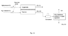
- a Solid Oxide Electrolysis Cell (SOEC) stack system for producing CO is disclosed as seen on Fig. 2 .
- the system comprises an SOEC stack.
- the electrolysis cells in the stack each has a fuel side and an oxygen side, hence, when all the cells are put on top of each other to form a stack, the stack has a fuel side and an oxygen side.
- the stack has a fuel side inlet and outlet and an oxygen side inlet and outlet.
- the configuration of the inlets and outlets may be of any kind known in the art such as internal manifolded, external manifolded or a combination of these.
- This cleaning of the process gas is done in a process gas separator downstream the SOEC stack.
- the process gas separator has a process gas inlet and a first and a second process gas outlet.
- the process gas is fed to the process gas separator inlet via process gas piping when it exits the SOEC stack from the fuel side outlet.
- Cleaned process gas, CO with a purity approaching 100% exits the process gas separator via the first process gas outlet.
- Separated process gas which comprises CO2 and CO exits the process gas separator from the second process gas outlet.
- the process gas separator demands a certain pressure of the process gas entering.
- an ejector is provided downstream the SOEC stack and upstream of the process gas separator.
- the ejector provides a pressure increase to the process gas exiting the SOEC stack by means of injection of high pressure CO2. This is feasible since the CO2 feed is normally stored in liquid form under elevated pressure, whereas the SOEC unit operates close to ambient conditions and therefore the feed gas pressure is usually reduced over a reduction valve up-stream from the SOEC unit. In-stead of the use of a reduction valve, at least a part of the high pressure feed gas may thus be lead through the ejector for pressure reduction and thereby increasing the process gas pressure upstream the process gas separator.
- the ejector hence provides pressure for the process gas separation, but also reduces the CO content in the feed gas for the process gas purification due to the injection of CO2. This may result in a lower yield of CO of the purification, but since the ejector is replacing a compressor, it provides a cheaper and less complicated unit with a lower footprint.
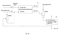
- a further second ejector is arranged between the process gas separator and the SOEC stack as seen on Fig. 3 , providing recycling of at least a part of the process gas from the second process gas outlet, via this second ejector to the fuel side inlet of the SOEC stack.
- Piping connects the second process gas outlet with the ejector and further connects the ejector to the fuel side of the SOEC stack.
- the recycle of at least a part of the process gas from the second process gas outlet to the fuel side of the SOEC stack reduces the consumption of CO2 and also lowers the waste of CO2 from the system.
- the recycling requires a slight increase in pressure of the recycle gas to overcome the pressure drop in the system. This pressure increase is provided by the second ejector.
- carbon monoxide is produced from carbon dioxide (CO2) in a solid oxide electrolysis cell (SOEC) stack, wherein CO 2 is led to the fuel side of the SOEC with an applied current, said process further comprising:
- the principle underlying the present embodiment consists in leading CO 2 to the fuel side of an SOEC with an applied current to convert CO 2 to CO and transport the oxygen surplus to the oxygen side of the SOEC. Air, nitrogen or carbon dioxide may be used to flush the oxygen side. Flushing the oxygen side of the SOEC has two advantages, more specifically (1) reducing the oxygen concentration and related corrosive effects and (2) providing means for feeding energy into the SOEC, operating it endothermic.
- the product stream from the SOEC contains mixed CO and CO 2 , which is led to a separation process such as pressure swing adsorption (PSA), temperature swing adsorption (TSA), membrane separation, cryogenic separation or liquid scrubber technology, such as wash with N-methyl-diethanolamine (MDEA).
- PSA pressure swing adsorption
- TSA temperature swing adsorption
- MDEA cryogenic separation
- liquid scrubber technology such as wash with N-methyl-diethanolamine (MDEA).
- PSA is especially suitable for the production of high purity CO according to the present invention.
- Carbon dioxide is the most abundant impurity.
- trace amounts of N 2 and H 2 may be present in the feed gas to the PSA unit.
- an adsorption comprising at least two adsorption columns, each containing adsorbents exhibiting selective adsorption properties towards carbon dioxide, can be used to remove CO 2 from the gas mixture.
- a second adsorption step can be employed to further remove carbon dioxide in addition to other pollutants such as nitrogen.
- This adsorption step comprises at least two adsorption columns, each containing adsorbents exhibiting selective adsorption properties towards carbon monoxide.
- Such an adsorption step may be used alone or as a second step in combination with the above mentioned adsorption step selective towards CO 2 .
- Adsorbents being selective regarding carbon monoxide adsorption include activated carbon, natural zeolites, synthetic zeolites, polystyrene or mixtures thereof.
- addition of copper or aluminium halides to any of the materials mentioned above to introduce monovalent copper ions and/or trivalent aluminium onto the materials is beneficial with respect to carbon monoxide selectivity and capacity.
- the addition of Cu or Al can be combined with impregnation of carbon onto the carrier to preserve the oxidation stage of Cu and Al.
- copper ions can be introduced into the zeolite material by ion exchange to increase the carbon monoxide selectivity and capacity.
- N 2 is difficult to separate effectively from CO in the downstream purification process which, as mentioned, uses PSA, TSA, membrane separation, cryogenic separation or liquid scrubber technology, such as wash with N-methyl-diethanolamine (MDEA).
- MDEA N-methyl-diethanolamine
- the electrolysis process in the SOEC requires an operating temperature between 650 and 850°C.
- the overall operation can consume heat (i.e. be endothermic), it can be thermoneutral or it can generate heat (i.e. be exothermic). Any operation carried out at such high temperatures also leads to a significant heat loss. This means that typically it will require external heating to reach and maintain the desired operating temperature.
- external heaters are used to heat the inlet gas on the oxygen side and the fuel side in order to supply heat to the SOEC stack, thereby mitigating this issue.
- Such external heaters are also useful during start-up as they can provide heat to help the SOEC reach its operating temperature. Suitable feed gas temperatures would be around 700 to 850°C.
- the external heaters can be electrical, but gas or liquid fuelled external heaters may also be used.
- the hot exhaust gas on the oxygen side and the fuel side may be utilized to heat the inlet gas. This is another way to maintain a suitable operating temperature for the SOEC and at the same time reduce the load on the heaters.
- mass (O 2 ) is transferred from the fuel side to the oxygen side, which leads to a limitation on the maximum temperature that can be reached in the feed effluent heat exchanger on the fuel side alone.
- a third feed effluent heat exchanger is implemented, said third heat exchanger transferring heat from the hot outlet side of the feed effluent heat exchanger on the oxygen side to the cold inlet of the feed effluent heat exchanger on the fuel side.
- feed effluent heat exchangers increases the efficiency with respect to power consumption of the plant, and it also greatly reduces the load on the high temperature heaters.
- the feed effluent heat exchangers will slow down and restrict the maximum rate of cooling by insertion of cold gases at the feed and purge inputs.
- fast cooling is desirable when electrical anode protection (EAP) is used during a power failure, where the electrical protection is provided by a battery back-up.
- EAP electrical anode protection
- the stack should be cooled to a temperature below the cathode/nickel oxidation temperature (e.g. 400°C) before the battery back-up power is used.
- a tie-in point is designed in between the high temperature heater and the SOEC, where a cooling medium such as air, N 2 or CO 2 can be added to the system and thus the cooling down rate can be increased and independently controlled.
- This tie-in point can be introduced on the anode side as well as on the cathode side of the SOEC.
- the gas connections for the heating and the cooling flows may be identical.
- the feed effluent heat exchanger employed on the cathode side of the SOEC may be subject to corrosion due to carbon formation in the carbon monoxide-rich atmosphere present on this side.
- This type of corrosion is generally renowned as metal dusting, and it may be mitigated by choosing an appropriate material or coating with respect to the heat exchanger and the heat exchanger conditions.
- An alternative solution to the metal dusting issue is to simply quench the gas coming from the cathode side of the SOEC to a temperature around 400-600°C, where metal dusting is kinetically inhibited.
- the quench should be performed with an inert gas such as N 2 , H 2 O, but most preferably with CO 2 .
- the feed effluent heat exchanger is still in service, but now utilizing the heat from a temperature range within 400-600°C, most preferably within 400-550°C, instead of from the SOEC operating temperature. This obviously reduces the overall efficiency of the plant with respect to heat and CO 2 consumption, but it does mitigate the metal dusting issue and it is an alternative to using more exotic materials on the cathode side.
- the SOEC unit together with the preheaters on the cathode side and the anode side as well as the feed effluent heat exchangers placed directly downstream from the SOEC unit comprise an entity called the SOEC core.
- This core is encapsulated and thermally insulated towards the surroundings to mitigate heat loss from and thermal gradients within these units which are operating at high temperatures.
- the core shell can be connected to the PSA purge line in order to assure that any leakage of CO is oxidized to CO 2 in the oxidation unit.
- the outlet stream from the oxygen side (anode side) of the SOEC is led to the oxidation unit to ensure that any leakage of CO into the oxygen side of the system is also oxidized into CO 2 .
- separate oxidation units may be established for the SOEC core purge and for the oxygen side outlet of the SOEC unit.
- these two streams may also share one common oxidizing unit.
- this catalytic oxidizing unit would include a catalytic oxidation reactor utilizing a catalyst.
- Said catalyst comprises a noble metal catalyst, such as Pt or Pd optionally combined with V 2 O 5 and WO 3 on a TiO 2 or alumina carrier, and the catalyst operates at temperatures above 100°C, preferably between 150 and 250°C.
- the CO 2 source is available at elevated pressure, whereas the SOEC is operating close to atmospheric pressure.
- a compressor between the SOEC and the separation process such as pressure swing adsorption (PSA)
- PSA pressure swing adsorption
- Adsorbents or absorbents are used upstream from the SOEC to remove undesired contaminants in the gas.
- Sulfur species and siloxanes in particular, but also other contaminants, such as halogens and higher hydrocarbons (e.g. benzene), are known to poison solid oxide cells.
- Such compounds can be absorbed, e.g. with active carbon or absorbents based on alumina, ZnO, Ni or Cu, such as Topsoe HTZ-51, Topsoe SC-101 and Topsoe ST-101.
- Carbon formation can also be suppressed by addition of H 2 S. Both carbon formation and metal dusting are normally considered to take place through the following reactions: 2CO ⁇ C + CO 2 (Boudouard reaction) and H 2 + CO ⁇ H 2 O + C (CO reduction)
- H 2 S does not affect the thermodynamic potential for metal dusting, but it pacifies the metal surfaces so that the sites, where the carbon-forming reactions would take place, are blocked.
- H 2 S to the feed stream to a level of H 2 S between 50 ppb and 2 ppm, most preferably between 100 ppb and 1 ppm, would effectively suppress carbon formation in the SOEC stack, i.e. in the Ni-containing cathode, and also protect downstream equipment from metal dusting attacks.
- the relatively low level mentioned above is enough to suppress the formation of carbon, and at the same time it does not cause any detrimental effects on the SOEC stack performance.
- H 2 S can be added to the feed gas just downstream from the feed gas purification unit to protect the SOEC and the downstream equipment from carbon formation and metal dusting.
- H 2 S can be added just downstream from the SOEC to only protect the downstream equipment from metal dusting.
- the same adsorbents as used for the feed gas purification can be used, i.e. active carbon or adsorbents based on alumina, ZnO, Ni or Cu, such as Topsoe HTZ-51, Topsoe SC-101 and Topsoe ST-101.
- the purification unit is preferably placed between the product gas compressor or ejector and the product purification unit.
- H 2 can be removed by selective oxidation of hydrogen: 2H 2 + O 2 ⁇ 2H 2 O
- the water formed is easily separated using cooling and condensation. This will make it possible to use H 2 in any SOEC operation where the target product is CO.
- H 2 is oxidized over oxidation catalysts at a lower temperature than CO.
- the applicable temperature level depends on the catalyst.
- a Pd or Pt catalyst can be expected to oxidize H 2 at temperature levels from ambient temperature to 70°C, whereas temperatures above 150°C are needed to oxidize CO.
- the CO/CO 2 product stream is effectively cleaned from H 2 .
- O 2 can be drawn conveniently from the O 2 -CO 2 mix on the anode side of the SOEC.
- the compartment around the stack may be purged with CO 2 .
- a heater is installed to bring the inlet CO 2 gas, utilized as a compartment purge, up to the operating temperature of the SOEC stack or above.
- This heater could for example be applied as a radiant heater, where the heater is incorporated in the CO 2 purge gas manifold, simultaneously heating the physical perimeter of the stack and the inlet CO 2 purge gas.
- the radiant heater can replace the oxygen side inlet heater, or alternatively it can be used as an additional heater which is used to reduce the time for cold start-up.
- the current invention focuses on applications, where carbon monoxide is the desired product, but the principles applied and the process configurations are also valid for the cases, where a mixture of CO 2 and steam comprises the feed stock and a mixture of hydrogen and CO is the desired product.
- a mixture of CO 2 and steam comprises the feed stock and a mixture of hydrogen and CO is the desired product.
- steam will follow CO 2 and H 2 will follow the CO product gas.
- the final PSA step would separate H 2 from CO and is thus only applicable in cases where splitting H 2 from CO is desired for the downstream process.
- steam is preferably removed from the product stream upstream from the product gas separation unit.
Priority Applications (1)
| Application Number | Priority Date | Filing Date | Title |
|---|---|---|---|
| EP14166323.7A EP2940773A1 (de) | 2014-04-29 | 2014-04-29 | Auswerfer für Festoxid-Elektrolysezellenstapelsystem |
Applications Claiming Priority (1)
| Application Number | Priority Date | Filing Date | Title |
|---|---|---|---|
| EP14166323.7A EP2940773A1 (de) | 2014-04-29 | 2014-04-29 | Auswerfer für Festoxid-Elektrolysezellenstapelsystem |
Publications (1)
| Publication Number | Publication Date |
|---|---|
| EP2940773A1 true EP2940773A1 (de) | 2015-11-04 |
Family
ID=50624472
Family Applications (1)
| Application Number | Title | Priority Date | Filing Date |
|---|---|---|---|
| EP14166323.7A Withdrawn EP2940773A1 (de) | 2014-04-29 | 2014-04-29 | Auswerfer für Festoxid-Elektrolysezellenstapelsystem |
Country Status (1)
| Country | Link |
|---|---|
| EP (1) | EP2940773A1 (de) |
Cited By (22)
| Publication number | Priority date | Publication date | Assignee | Title |
|---|---|---|---|---|
| WO2018228716A1 (de) | 2017-06-14 | 2018-12-20 | Linde Aktiengesellschaft | Verfahren und anlage zur herstellung eines kohlenmonoxid enthaltenden gasprodukts |
| DE102017005681A1 (de) | 2017-06-14 | 2018-12-20 | Linde Aktiengesellschaft | Verfahren und Anlage zur Herstellung eines Kohlenmonoxid enthaltenden Gasprodukts |
| WO2018228717A1 (de) | 2017-06-14 | 2018-12-20 | Linde Aktiengesellschaft | Verfahren und anlage zur herstellung eines kohlenmonoxid enthaltenden gasprodukts |
| EP3511441A1 (de) | 2018-01-12 | 2019-07-17 | Linde Aktiengesellschaft | Herstellung eines kohlenmonoxid enthaltenden gasprodukts |
| EP3511442A1 (de) | 2018-01-12 | 2019-07-17 | Linde Aktiengesellschaft | Herstellung eines kohlenmonoxid enthaltenden gasprodukts |
| WO2019158308A1 (de) | 2018-02-15 | 2019-08-22 | Siemens Aktiengesellschaft | Anlage zur elektrochemischen herstellung eines co-haltigen gasprodukts |
| DE102018202337A1 (de) | 2018-02-15 | 2019-08-22 | Linde Aktiengesellschaft | Elektrochemische Herstellung eines Gases umfassend CO mit Zwischenkühlung des Elektrolytstroms |
| WO2019158305A1 (de) | 2018-02-15 | 2019-08-22 | Siemens Aktiengesellschaft | Elektrochemische herstellung von kohlenstoffmonoxid und/oder synthesegas |
| DE102018003343A1 (de) | 2018-04-24 | 2019-10-24 | Linde Aktiengesellschaft | Verfahren und Anlage zur Herstellung von Ethanol |
| DE102018003342A1 (de) | 2018-04-24 | 2019-10-24 | Linde Aktiengesellschaft | Herstellung eines zumindest Kohlenmonoxid enthaltenden Gasprodukts |
| DE102018003332A1 (de) | 2018-04-24 | 2019-10-24 | Linde Aktiengesellschaft | Herstellung eines Syntheseprodukts |
| WO2020104053A1 (de) * | 2018-11-22 | 2020-05-28 | Linde Aktiengesellschaft | Verfahren zum wechsel der betreibsweise einer elektrolyseanlage sowie elektrolyseanlage |
| EP3378972A3 (de) * | 2017-03-21 | 2020-09-30 | Kabushiki Kaisha Toyota Chuo Kenkyusho | Elektrisches energiespeichersystem und elektrisches energiespeicher- und -versorgungssystem |
| WO2021073769A1 (de) | 2019-10-18 | 2021-04-22 | Linde Gmbh | Verfahren und anlage zur herstellung eines an kohlenstoffmonoxidreichen gasprodukts |
| DE102020000476A1 (de) | 2020-01-27 | 2021-07-29 | Linde Gmbh | Verfahren und Anlage zur Herstellung von Wasserstoff |
| DE102020000937A1 (de) | 2020-02-14 | 2021-08-19 | Linde Gmbh | Verfahren und Anlage zur Bereitstellung eines Industrieprodukts unter Verwendung von Sauerstoff |
| CN113906599A (zh) * | 2019-07-02 | 2022-01-07 | Avl李斯特有限公司 | Soec系统和soec系统运行方法 |
| WO2023288174A1 (en) * | 2021-07-14 | 2023-01-19 | Saudi Arabian Oil Company | Solid oxide electrolytic cells using zeolite-templated carbon (ztc) as electrocatalyst |
| TWI816374B (zh) * | 2022-04-21 | 2023-09-21 | 國立臺灣大學 | 還原二氧化碳的電化學設備及其系統 |
| EP4324957A1 (de) | 2022-08-19 | 2024-02-21 | Linde GmbH | Verfahren und anlage zur herstellung eines wasserstoff enthaltenden produkts |
| EP4345191A1 (de) | 2022-09-30 | 2024-04-03 | Linde GmbH | Verfahren und anlage zur herstellung eines wasserstoff enthaltend en produkts unter einsatz einer elektrolyse |
| EP4345086A1 (de) | 2022-09-30 | 2024-04-03 | Linde GmbH | Verfahren und anlage zur herstellung von methanol |
Citations (8)
| Publication number | Priority date | Publication date | Assignee | Title |
|---|---|---|---|---|
| US20070045125A1 (en) | 2005-08-25 | 2007-03-01 | Hartvigsen Joseph J | Electrochemical Cell for Production of Synthesis Gas Using Atmospheric Air and Water |
| JP2007128786A (ja) * | 2005-11-04 | 2007-05-24 | Toyota Central Res & Dev Lab Inc | 燃料電池システム |
| US20080023338A1 (en) | 2006-07-31 | 2008-01-31 | Battelle Energy Alliance, Llc | High temperature electrolysis for syngas production |
| WO2009059571A1 (de) * | 2007-11-10 | 2009-05-14 | Horst-Eckart Vollmar | Hochtemperaturbrennstoffzellensystem mit teilweisem kreislauf des anodenabgases und ausschleusung von gaskomponenten |
| US8138380B2 (en) | 2007-07-13 | 2012-03-20 | University Of Southern California | Electrolysis of carbon dioxide in aqueous media to carbon monoxide and hydrogen for production of methanol |
| US20120228150A1 (en) | 2011-03-08 | 2012-09-13 | Kang Bruce S | Co2 decomposition via oxygen deficient ferrite electrodes using solid oxide electrolyser cell |
| US8366902B2 (en) | 2008-03-24 | 2013-02-05 | Battelle Energy Alliance, Llc | Methods and systems for producing syngas |
| WO2013131778A2 (en) * | 2012-03-05 | 2013-09-12 | Haldor Topsøe A/S | Apparatus for production of high purity carbon monoxide |
-
2014
- 2014-04-29 EP EP14166323.7A patent/EP2940773A1/de not_active Withdrawn
Patent Citations (8)
| Publication number | Priority date | Publication date | Assignee | Title |
|---|---|---|---|---|
| US20070045125A1 (en) | 2005-08-25 | 2007-03-01 | Hartvigsen Joseph J | Electrochemical Cell for Production of Synthesis Gas Using Atmospheric Air and Water |
| JP2007128786A (ja) * | 2005-11-04 | 2007-05-24 | Toyota Central Res & Dev Lab Inc | 燃料電池システム |
| US20080023338A1 (en) | 2006-07-31 | 2008-01-31 | Battelle Energy Alliance, Llc | High temperature electrolysis for syngas production |
| US8138380B2 (en) | 2007-07-13 | 2012-03-20 | University Of Southern California | Electrolysis of carbon dioxide in aqueous media to carbon monoxide and hydrogen for production of methanol |
| WO2009059571A1 (de) * | 2007-11-10 | 2009-05-14 | Horst-Eckart Vollmar | Hochtemperaturbrennstoffzellensystem mit teilweisem kreislauf des anodenabgases und ausschleusung von gaskomponenten |
| US8366902B2 (en) | 2008-03-24 | 2013-02-05 | Battelle Energy Alliance, Llc | Methods and systems for producing syngas |
| US20120228150A1 (en) | 2011-03-08 | 2012-09-13 | Kang Bruce S | Co2 decomposition via oxygen deficient ferrite electrodes using solid oxide electrolyser cell |
| WO2013131778A2 (en) * | 2012-03-05 | 2013-09-12 | Haldor Topsøe A/S | Apparatus for production of high purity carbon monoxide |
Non-Patent Citations (1)
| Title |
|---|
| "Electrolysis of Carbon Dioxide in Solid Oxide Electrolysis Cells", JOURNAL OF POWER SOURCES, vol. 193, 2009, pages 349 - 358 |
Cited By (47)
| Publication number | Priority date | Publication date | Assignee | Title |
|---|---|---|---|---|
| EP3378972A3 (de) * | 2017-03-21 | 2020-09-30 | Kabushiki Kaisha Toyota Chuo Kenkyusho | Elektrisches energiespeichersystem und elektrisches energiespeicher- und -versorgungssystem |
| WO2018228716A1 (de) | 2017-06-14 | 2018-12-20 | Linde Aktiengesellschaft | Verfahren und anlage zur herstellung eines kohlenmonoxid enthaltenden gasprodukts |
| DE102017005681A1 (de) | 2017-06-14 | 2018-12-20 | Linde Aktiengesellschaft | Verfahren und Anlage zur Herstellung eines Kohlenmonoxid enthaltenden Gasprodukts |
| WO2018228717A1 (de) | 2017-06-14 | 2018-12-20 | Linde Aktiengesellschaft | Verfahren und anlage zur herstellung eines kohlenmonoxid enthaltenden gasprodukts |
| DE102017005678A1 (de) | 2017-06-14 | 2018-12-20 | Linde Aktiengesellschaft | Verfahren und Anlage zur Herstellung eines Kohlenmonoxid enthaltenden Gasprodukts |
| WO2018228718A1 (de) | 2017-06-14 | 2018-12-20 | Linde Aktiengesellschaft | Verfahren und anlage zur herstellung eines kohlenmonoxid enthaltenden gasprodukts |
| DE102017005680A1 (de) | 2017-06-14 | 2018-12-20 | Linde Aktiengesellschaft | Verfahren und Anlage zur Herstellung eines Kohlenmonoxid enthaltenden Gasprodukts |
| CN110730830A (zh) * | 2017-06-14 | 2020-01-24 | 林德股份公司 | 用于生产含有一氧化碳的气体产物的方法和系统 |
| CN110770369A (zh) * | 2017-06-14 | 2020-02-07 | 林德股份公司 | 用于生产含有一氧化碳的气体产物的方法和系统 |
| US20200131647A1 (en) * | 2017-06-14 | 2020-04-30 | Linde Aktiengesellschaft | Method and system for producing a gas product containing carbon monoxide |
| EP3511441A1 (de) | 2018-01-12 | 2019-07-17 | Linde Aktiengesellschaft | Herstellung eines kohlenmonoxid enthaltenden gasprodukts |
| WO2019137827A1 (de) | 2018-01-12 | 2019-07-18 | Linde Aktiengesellschaft | Herstellung eines kohlenmonoxid enthaltenden gasprodukts |
| DE102018000213A1 (de) | 2018-01-12 | 2019-07-18 | Linde Aktiengesellschaft | Herstellung eines zumindest Kohlenmonoxid enthaltenden Gasprodukts |
| DE102018000214A1 (de) | 2018-01-12 | 2019-07-18 | Linde Aktiengesellschaft | Herstellung eines zumindest Kohlenmonoxid enthaltenden Gasprodukts |
| EP3511442A1 (de) | 2018-01-12 | 2019-07-17 | Linde Aktiengesellschaft | Herstellung eines kohlenmonoxid enthaltenden gasprodukts |
| WO2019158308A1 (de) | 2018-02-15 | 2019-08-22 | Siemens Aktiengesellschaft | Anlage zur elektrochemischen herstellung eines co-haltigen gasprodukts |
| WO2019158305A1 (de) | 2018-02-15 | 2019-08-22 | Siemens Aktiengesellschaft | Elektrochemische herstellung von kohlenstoffmonoxid und/oder synthesegas |
| US11105007B2 (en) | 2018-02-15 | 2021-08-31 | Siemens Aktiengesellschaft | Method for the electrochemical production of a gas product containing CO |
| DE102018202335A1 (de) | 2018-02-15 | 2019-08-22 | Linde Aktiengesellschaft | Anlage zur elektrochemischen Herstellung eines CO-haltigen Gasprodukts |
| CN111727276B (zh) * | 2018-02-15 | 2021-05-25 | 西门子股份公司 | 用于电化学制取包含co的气体产物的设备 |
| DE102018202337A1 (de) | 2018-02-15 | 2019-08-22 | Linde Aktiengesellschaft | Elektrochemische Herstellung eines Gases umfassend CO mit Zwischenkühlung des Elektrolytstroms |
| US11560633B2 (en) | 2018-02-15 | 2023-01-24 | Siemens Energy Global GmbH & Co. KG | Electrochemical production of carbon monoxide and/or syngas |
| DE102018202344A1 (de) | 2018-02-15 | 2019-08-22 | Siemens Aktiengesellschaft | Elektrochemische Herstellung von Kohlenstoffmonoxid und/oder Synthesegas |
| WO2019158307A1 (de) | 2018-02-15 | 2019-08-22 | Siemens Aktiengesellschaft | Elektrochemische herstellung eines gases umfassend co mit zwischenkühlung des elektrolytstroms |
| WO2019206450A1 (de) | 2018-04-24 | 2019-10-31 | Linde Aktiengesellschaft | Herstellung eines syntheseprodukts |
| WO2019206451A1 (de) | 2018-04-24 | 2019-10-31 | Linde Aktiengesellschaft | Herstellung eines zumindest kohlenmonoxid enthaltenden gasprodukts |
| DE102018003332A1 (de) | 2018-04-24 | 2019-10-24 | Linde Aktiengesellschaft | Herstellung eines Syntheseprodukts |
| DE102018003342A1 (de) | 2018-04-24 | 2019-10-24 | Linde Aktiengesellschaft | Herstellung eines zumindest Kohlenmonoxid enthaltenden Gasprodukts |
| DE102018003343A1 (de) | 2018-04-24 | 2019-10-24 | Linde Aktiengesellschaft | Verfahren und Anlage zur Herstellung von Ethanol |
| WO2020104053A1 (de) * | 2018-11-22 | 2020-05-28 | Linde Aktiengesellschaft | Verfahren zum wechsel der betreibsweise einer elektrolyseanlage sowie elektrolyseanlage |
| CN112969521A (zh) * | 2018-11-22 | 2021-06-15 | 林德有限责任公司 | 切换电解装置的运行方式的方法以及电解装置 |
| US20220010444A1 (en) * | 2018-11-22 | 2022-01-13 | Linde Gmbh | Method for changing the operating mode of an electrolysis system, and electrolysis system |
| CN113906599B (zh) * | 2019-07-02 | 2024-04-30 | Avl李斯特有限公司 | Soec系统和soec系统运行方法 |
| US11769890B2 (en) * | 2019-07-02 | 2023-09-26 | Avl List Gmbh | SOEC system and method for operating a SOEC system |
| CN113906599A (zh) * | 2019-07-02 | 2022-01-07 | Avl李斯特有限公司 | Soec系统和soec系统运行方法 |
| US20220367892A1 (en) * | 2019-07-02 | 2022-11-17 | Avl List Gmbh | Soec system and method for operating a soec system |
| WO2021073769A1 (de) | 2019-10-18 | 2021-04-22 | Linde Gmbh | Verfahren und anlage zur herstellung eines an kohlenstoffmonoxidreichen gasprodukts |
| DE102020000476A1 (de) | 2020-01-27 | 2021-07-29 | Linde Gmbh | Verfahren und Anlage zur Herstellung von Wasserstoff |
| WO2021151453A1 (de) | 2020-01-27 | 2021-08-05 | Linde Gmbh | Verfahren und anlage zur herstellung von wasserstoff |
| DE102020000937A1 (de) | 2020-02-14 | 2021-08-19 | Linde Gmbh | Verfahren und Anlage zur Bereitstellung eines Industrieprodukts unter Verwendung von Sauerstoff |
| WO2023288174A1 (en) * | 2021-07-14 | 2023-01-19 | Saudi Arabian Oil Company | Solid oxide electrolytic cells using zeolite-templated carbon (ztc) as electrocatalyst |
| TWI816374B (zh) * | 2022-04-21 | 2023-09-21 | 國立臺灣大學 | 還原二氧化碳的電化學設備及其系統 |
| EP4324957A1 (de) | 2022-08-19 | 2024-02-21 | Linde GmbH | Verfahren und anlage zur herstellung eines wasserstoff enthaltenden produkts |
| EP4345191A1 (de) | 2022-09-30 | 2024-04-03 | Linde GmbH | Verfahren und anlage zur herstellung eines wasserstoff enthaltend en produkts unter einsatz einer elektrolyse |
| EP4345086A1 (de) | 2022-09-30 | 2024-04-03 | Linde GmbH | Verfahren und anlage zur herstellung von methanol |
| WO2024068047A1 (de) | 2022-09-30 | 2024-04-04 | Linde Gmbh | Verfahren und anlage zur herstellung von methanol |
| WO2024068048A2 (de) | 2022-09-30 | 2024-04-04 | Linde Gmbh | Verfahren und anlage zur herstellung eines wasserstoff enthaltenden produkts unter einsatz einer elektrolyse |
Similar Documents
| Publication | Publication Date | Title |
|---|---|---|
| US10494728B2 (en) | Process for producing CO from CO2 in a solid oxide electrolysis cell | |
| EP2940773A1 (de) | Auswerfer für Festoxid-Elektrolysezellenstapelsystem | |
| CA2866312C (en) | Process for producing high purity carbon monoxide | |
| EP1908143B1 (de) | Brennstoffzellensystem mit teilweiser rückgewinnung von anodenabgas | |
| AU2017222158B2 (en) | Carbon monoxide production process optimized by SOEC | |
| EP2449617B1 (de) | Hochtemperatur-brennstoffzellensystem | |
| US20040191595A1 (en) | SORFC system and method with an exothermic net electrolysis reaction | |
| US20050123810A1 (en) | System and method for co-production of hydrogen and electrical energy | |
| US20060127714A1 (en) | Power generation apparatus | |
| Han et al. | High purity hydrogen generator for on-site hydrogen production | |
| CN110582880B (zh) | 燃料电池系统和用于操作燃料电池系统的方法 | |
| US11309563B2 (en) | High efficiency fuel cell system with hydrogen and syngas export | |
| EP3875426A1 (de) | Brennstoffzellensystem und regenerationsverfahren für abgas | |
| JP5098073B2 (ja) | エネルギーステーション | |
| JP2007164989A (ja) | 固体酸化物型燃料電池と水素製造工程との組み合わせ方法 | |
| WO2004086585A2 (en) | Sorfc system and method with an exothermic net electrolysis reaction | |
| WO2023100835A1 (ja) | オレフィン系化合物の製造装置 |
Legal Events
| Date | Code | Title | Description |
|---|---|---|---|
| PUAI | Public reference made under article 153(3) epc to a published international application that has entered the european phase |
Free format text: ORIGINAL CODE: 0009012 |
|
| AK | Designated contracting states |
Kind code of ref document: A1 Designated state(s): AL AT BE BG CH CY CZ DE DK EE ES FI FR GB GR HR HU IE IS IT LI LT LU LV MC MK MT NL NO PL PT RO RS SE SI SK SM TR |
|
| AX | Request for extension of the european patent |
Extension state: BA ME |
|
| STAA | Information on the status of an ep patent application or granted ep patent |
Free format text: STATUS: THE APPLICATION HAS BEEN WITHDRAWN |
|
| 18W | Application withdrawn |
Effective date: 20151116 |