EP2940747B1 - Wellenlängenumwandlungselement und lichtemittierende vorrichtung - Google Patents
Wellenlängenumwandlungselement und lichtemittierende vorrichtung Download PDFInfo
- Publication number
- EP2940747B1 EP2940747B1 EP13869816.2A EP13869816A EP2940747B1 EP 2940747 B1 EP2940747 B1 EP 2940747B1 EP 13869816 A EP13869816 A EP 13869816A EP 2940747 B1 EP2940747 B1 EP 2940747B1
- Authority
- EP
- European Patent Office
- Prior art keywords
- light
- wavelength conversion
- conversion member
- phosphor
- emitting device
- Prior art date
- Legal status (The legal status is an assumption and is not a legal conclusion. Google has not performed a legal analysis and makes no representation as to the accuracy of the status listed.)
- Active
Links
- 238000006243 chemical reaction Methods 0.000 title claims description 142
- OAICVXFJPJFONN-UHFFFAOYSA-N Phosphorus Chemical compound [P] OAICVXFJPJFONN-UHFFFAOYSA-N 0.000 claims description 104
- 239000002245 particle Substances 0.000 claims description 19
- XPIIDKFHGDPTIY-UHFFFAOYSA-N F.F.F.P Chemical compound F.F.F.P XPIIDKFHGDPTIY-UHFFFAOYSA-N 0.000 claims description 18
- 239000011572 manganese Substances 0.000 claims description 18
- -1 manganese-activated potassium Chemical class 0.000 claims description 17
- 229920005992 thermoplastic resin Polymers 0.000 claims description 14
- 239000004743 Polypropylene Substances 0.000 claims description 13
- 229920001155 polypropylene Polymers 0.000 claims description 13
- 229910019901 yttrium aluminum garnet Inorganic materials 0.000 claims description 12
- 239000003795 chemical substances by application Substances 0.000 claims description 8
- 229910052748 manganese Inorganic materials 0.000 claims description 8
- 230000003287 optical effect Effects 0.000 claims description 8
- 238000002834 transmittance Methods 0.000 claims description 8
- 238000000034 method Methods 0.000 claims description 6
- 238000000465 moulding Methods 0.000 claims description 6
- 230000005284 excitation Effects 0.000 claims description 4
- 229920000098 polyolefin Polymers 0.000 claims description 3
- 230000001186 cumulative effect Effects 0.000 claims description 2
- 230000001681 protective effect Effects 0.000 claims description 2
- 238000004519 manufacturing process Methods 0.000 claims 2
- 239000004793 Polystyrene Substances 0.000 claims 1
- 239000000203 mixture Substances 0.000 claims 1
- 229920002223 polystyrene Polymers 0.000 claims 1
- 229920005989 resin Polymers 0.000 description 28
- 239000011347 resin Substances 0.000 description 28
- 230000000052 comparative effect Effects 0.000 description 18
- 238000009877 rendering Methods 0.000 description 14
- 238000005516 engineering process Methods 0.000 description 9
- PWHULOQIROXLJO-UHFFFAOYSA-N Manganese Chemical compound [Mn] PWHULOQIROXLJO-UHFFFAOYSA-N 0.000 description 6
- 239000008188 pellet Substances 0.000 description 6
- 230000002411 adverse Effects 0.000 description 5
- 238000010276 construction Methods 0.000 description 5
- 239000000463 material Substances 0.000 description 5
- 239000000843 powder Substances 0.000 description 5
- 239000011159 matrix material Substances 0.000 description 4
- 238000010521 absorption reaction Methods 0.000 description 3
- 230000000694 effects Effects 0.000 description 3
- 230000006872 improvement Effects 0.000 description 3
- 238000009434 installation Methods 0.000 description 3
- KRHYYFGTRYWZRS-UHFFFAOYSA-N Fluorane Chemical compound F KRHYYFGTRYWZRS-UHFFFAOYSA-N 0.000 description 2
- 229910052688 Gadolinium Inorganic materials 0.000 description 2
- VYPSYNLAJGMNEJ-UHFFFAOYSA-N Silicium dioxide Chemical compound O=[Si]=O VYPSYNLAJGMNEJ-UHFFFAOYSA-N 0.000 description 2
- 239000000654 additive Substances 0.000 description 2
- 239000011521 glass Substances 0.000 description 2
- 238000005286 illumination Methods 0.000 description 2
- 238000002347 injection Methods 0.000 description 2
- 239000007924 injection Substances 0.000 description 2
- 238000001746 injection moulding Methods 0.000 description 2
- 238000005259 measurement Methods 0.000 description 2
- 150000004767 nitrides Chemical class 0.000 description 2
- TWNQGVIAIRXVLR-UHFFFAOYSA-N oxo(oxoalumanyloxy)alumane Chemical compound O=[Al]O[Al]=O TWNQGVIAIRXVLR-UHFFFAOYSA-N 0.000 description 2
- 229920005668 polycarbonate resin Polymers 0.000 description 2
- 239000004431 polycarbonate resin Substances 0.000 description 2
- 229910052814 silicon oxide Inorganic materials 0.000 description 2
- 239000000243 solution Substances 0.000 description 2
- 239000003381 stabilizer Substances 0.000 description 2
- 238000012360 testing method Methods 0.000 description 2
- VGGSQFUCUMXWEO-UHFFFAOYSA-N Ethene Chemical group C=C VGGSQFUCUMXWEO-UHFFFAOYSA-N 0.000 description 1
- 239000005977 Ethylene Substances 0.000 description 1
- 229910052693 Europium Inorganic materials 0.000 description 1
- KRHYYFGTRYWZRS-UHFFFAOYSA-M Fluoride anion Chemical compound [F-] KRHYYFGTRYWZRS-UHFFFAOYSA-M 0.000 description 1
- VAYOSLLFUXYJDT-RDTXWAMCSA-N Lysergic acid diethylamide Chemical compound C1=CC(C=2[C@H](N(C)C[C@@H](C=2)C(=O)N(CC)CC)C2)=C3C2=CNC3=C1 VAYOSLLFUXYJDT-RDTXWAMCSA-N 0.000 description 1
- 206010033546 Pallor Diseases 0.000 description 1
- 229910003564 SiAlON Inorganic materials 0.000 description 1
- UCKMPCXJQFINFW-UHFFFAOYSA-N Sulphide Chemical compound [S-2] UCKMPCXJQFINFW-UHFFFAOYSA-N 0.000 description 1
- YKTSYUJCYHOUJP-UHFFFAOYSA-N [O--].[Al+3].[Al+3].[O-][Si]([O-])([O-])[O-] Chemical compound [O--].[Al+3].[Al+3].[O-][Si]([O-])([O-])[O-] YKTSYUJCYHOUJP-UHFFFAOYSA-N 0.000 description 1
- 239000006096 absorbing agent Substances 0.000 description 1
- 239000002253 acid Substances 0.000 description 1
- 150000007513 acids Chemical class 0.000 description 1
- 230000004075 alteration Effects 0.000 description 1
- 239000003963 antioxidant agent Substances 0.000 description 1
- 230000003078 antioxidant effect Effects 0.000 description 1
- 239000012752 auxiliary agent Substances 0.000 description 1
- 230000008901 benefit Effects 0.000 description 1
- 239000000919 ceramic Substances 0.000 description 1
- 239000011248 coating agent Substances 0.000 description 1
- 239000008199 coating composition Substances 0.000 description 1
- 238000000576 coating method Methods 0.000 description 1
- 238000004040 coloring Methods 0.000 description 1
- 238000013461 design Methods 0.000 description 1
- 238000011161 development Methods 0.000 description 1
- 238000000295 emission spectrum Methods 0.000 description 1
- 238000011156 evaluation Methods 0.000 description 1
- 230000008020 evaporation Effects 0.000 description 1
- 238000001704 evaporation Methods 0.000 description 1
- 229910052733 gallium Inorganic materials 0.000 description 1
- 229910052736 halogen Inorganic materials 0.000 description 1
- 150000002367 halogens Chemical class 0.000 description 1
- 238000010438 heat treatment Methods 0.000 description 1
- 229910001385 heavy metal Inorganic materials 0.000 description 1
- 230000000415 inactivating effect Effects 0.000 description 1
- 229910052909 inorganic silicate Inorganic materials 0.000 description 1
- 230000001678 irradiating effect Effects 0.000 description 1
- 230000007774 longterm Effects 0.000 description 1
- 239000000314 lubricant Substances 0.000 description 1
- 239000000155 melt Substances 0.000 description 1
- 229910001512 metal fluoride Inorganic materials 0.000 description 1
- 238000003801 milling Methods 0.000 description 1
- SIWVEOZUMHYXCS-UHFFFAOYSA-N oxo(oxoyttriooxy)yttrium Chemical compound O=[Y]O[Y]=O SIWVEOZUMHYXCS-UHFFFAOYSA-N 0.000 description 1
- 230000002093 peripheral effect Effects 0.000 description 1
- 239000004033 plastic Substances 0.000 description 1
- 239000004417 polycarbonate Substances 0.000 description 1
- 229920000515 polycarbonate Polymers 0.000 description 1
- 229920005604 random copolymer Polymers 0.000 description 1
- 230000009467 reduction Effects 0.000 description 1
- 230000004044 response Effects 0.000 description 1
- 238000000790 scattering method Methods 0.000 description 1
- 238000005507 spraying Methods 0.000 description 1
- 239000007858 starting material Substances 0.000 description 1
- 239000000454 talc Substances 0.000 description 1
- 229910052623 talc Inorganic materials 0.000 description 1
Images


Classifications
-
- F—MECHANICAL ENGINEERING; LIGHTING; HEATING; WEAPONS; BLASTING
- F21—LIGHTING
- F21K—NON-ELECTRIC LIGHT SOURCES USING LUMINESCENCE; LIGHT SOURCES USING ELECTROCHEMILUMINESCENCE; LIGHT SOURCES USING CHARGES OF COMBUSTIBLE MATERIAL; LIGHT SOURCES USING SEMICONDUCTOR DEVICES AS LIGHT-GENERATING ELEMENTS; LIGHT SOURCES NOT OTHERWISE PROVIDED FOR
- F21K9/00—Light sources using semiconductor devices as light-generating elements, e.g. using light-emitting diodes [LED] or lasers
- F21K9/60—Optical arrangements integrated in the light source, e.g. for improving the colour rendering index or the light extraction
- F21K9/64—Optical arrangements integrated in the light source, e.g. for improving the colour rendering index or the light extraction using wavelength conversion means distinct or spaced from the light-generating element, e.g. a remote phosphor layer
-
- C—CHEMISTRY; METALLURGY
- C09—DYES; PAINTS; POLISHES; NATURAL RESINS; ADHESIVES; COMPOSITIONS NOT OTHERWISE PROVIDED FOR; APPLICATIONS OF MATERIALS NOT OTHERWISE PROVIDED FOR
- C09K—MATERIALS FOR MISCELLANEOUS APPLICATIONS, NOT PROVIDED FOR ELSEWHERE
- C09K11/00—Luminescent, e.g. electroluminescent, chemiluminescent materials
- C09K11/02—Use of particular materials as binders, particle coatings or suspension media therefor
-
- C—CHEMISTRY; METALLURGY
- C09—DYES; PAINTS; POLISHES; NATURAL RESINS; ADHESIVES; COMPOSITIONS NOT OTHERWISE PROVIDED FOR; APPLICATIONS OF MATERIALS NOT OTHERWISE PROVIDED FOR
- C09K—MATERIALS FOR MISCELLANEOUS APPLICATIONS, NOT PROVIDED FOR ELSEWHERE
- C09K11/00—Luminescent, e.g. electroluminescent, chemiluminescent materials
- C09K11/08—Luminescent, e.g. electroluminescent, chemiluminescent materials containing inorganic luminescent materials
- C09K11/61—Luminescent, e.g. electroluminescent, chemiluminescent materials containing inorganic luminescent materials containing fluorine, chlorine, bromine, iodine or unspecified halogen elements
- C09K11/615—Halogenides
- C09K11/616—Halogenides with alkali or alkaline earth metals
-
- C—CHEMISTRY; METALLURGY
- C09—DYES; PAINTS; POLISHES; NATURAL RESINS; ADHESIVES; COMPOSITIONS NOT OTHERWISE PROVIDED FOR; APPLICATIONS OF MATERIALS NOT OTHERWISE PROVIDED FOR
- C09K—MATERIALS FOR MISCELLANEOUS APPLICATIONS, NOT PROVIDED FOR ELSEWHERE
- C09K11/00—Luminescent, e.g. electroluminescent, chemiluminescent materials
- C09K11/08—Luminescent, e.g. electroluminescent, chemiluminescent materials containing inorganic luminescent materials
- C09K11/61—Luminescent, e.g. electroluminescent, chemiluminescent materials containing inorganic luminescent materials containing fluorine, chlorine, bromine, iodine or unspecified halogen elements
- C09K11/617—Silicates
-
- C—CHEMISTRY; METALLURGY
- C09—DYES; PAINTS; POLISHES; NATURAL RESINS; ADHESIVES; COMPOSITIONS NOT OTHERWISE PROVIDED FOR; APPLICATIONS OF MATERIALS NOT OTHERWISE PROVIDED FOR
- C09K—MATERIALS FOR MISCELLANEOUS APPLICATIONS, NOT PROVIDED FOR ELSEWHERE
- C09K11/00—Luminescent, e.g. electroluminescent, chemiluminescent materials
- C09K11/08—Luminescent, e.g. electroluminescent, chemiluminescent materials containing inorganic luminescent materials
- C09K11/77—Luminescent, e.g. electroluminescent, chemiluminescent materials containing inorganic luminescent materials containing rare earth metals
- C09K11/7766—Luminescent, e.g. electroluminescent, chemiluminescent materials containing inorganic luminescent materials containing rare earth metals containing two or more rare earth metals
- C09K11/7774—Aluminates
-
- C—CHEMISTRY; METALLURGY
- C09—DYES; PAINTS; POLISHES; NATURAL RESINS; ADHESIVES; COMPOSITIONS NOT OTHERWISE PROVIDED FOR; APPLICATIONS OF MATERIALS NOT OTHERWISE PROVIDED FOR
- C09K—MATERIALS FOR MISCELLANEOUS APPLICATIONS, NOT PROVIDED FOR ELSEWHERE
- C09K11/00—Luminescent, e.g. electroluminescent, chemiluminescent materials
- C09K11/08—Luminescent, e.g. electroluminescent, chemiluminescent materials containing inorganic luminescent materials
- C09K11/77—Luminescent, e.g. electroluminescent, chemiluminescent materials containing inorganic luminescent materials containing rare earth metals
- C09K11/7783—Luminescent, e.g. electroluminescent, chemiluminescent materials containing inorganic luminescent materials containing rare earth metals containing two or more rare earth metals one of which being europium
- C09K11/7792—Aluminates
-
- F—MECHANICAL ENGINEERING; LIGHTING; HEATING; WEAPONS; BLASTING
- F21—LIGHTING
- F21K—NON-ELECTRIC LIGHT SOURCES USING LUMINESCENCE; LIGHT SOURCES USING ELECTROCHEMILUMINESCENCE; LIGHT SOURCES USING CHARGES OF COMBUSTIBLE MATERIAL; LIGHT SOURCES USING SEMICONDUCTOR DEVICES AS LIGHT-GENERATING ELEMENTS; LIGHT SOURCES NOT OTHERWISE PROVIDED FOR
- F21K9/00—Light sources using semiconductor devices as light-generating elements, e.g. using light-emitting diodes [LED] or lasers
- F21K9/20—Light sources comprising attachment means
- F21K9/23—Retrofit light sources for lighting devices with a single fitting for each light source, e.g. for substitution of incandescent lamps with bayonet or threaded fittings
- F21K9/232—Retrofit light sources for lighting devices with a single fitting for each light source, e.g. for substitution of incandescent lamps with bayonet or threaded fittings specially adapted for generating an essentially omnidirectional light distribution, e.g. with a glass bulb
-
- F—MECHANICAL ENGINEERING; LIGHTING; HEATING; WEAPONS; BLASTING
- F21—LIGHTING
- F21V—FUNCTIONAL FEATURES OR DETAILS OF LIGHTING DEVICES OR SYSTEMS THEREOF; STRUCTURAL COMBINATIONS OF LIGHTING DEVICES WITH OTHER ARTICLES, NOT OTHERWISE PROVIDED FOR
- F21V3/00—Globes; Bowls; Cover glasses
- F21V3/04—Globes; Bowls; Cover glasses characterised by materials, surface treatments or coatings
-
- F—MECHANICAL ENGINEERING; LIGHTING; HEATING; WEAPONS; BLASTING
- F21—LIGHTING
- F21V—FUNCTIONAL FEATURES OR DETAILS OF LIGHTING DEVICES OR SYSTEMS THEREOF; STRUCTURAL COMBINATIONS OF LIGHTING DEVICES WITH OTHER ARTICLES, NOT OTHERWISE PROVIDED FOR
- F21V9/00—Elements for modifying spectral properties, polarisation or intensity of the light emitted, e.g. filters
- F21V9/30—Elements containing photoluminescent material distinct from or spaced from the light source
- F21V9/32—Elements containing photoluminescent material distinct from or spaced from the light source characterised by the arrangement of the photoluminescent material
-
- H—ELECTRICITY
- H01—ELECTRIC ELEMENTS
- H01L—SEMICONDUCTOR DEVICES NOT COVERED BY CLASS H10
- H01L33/00—Semiconductor devices with at least one potential-jump barrier or surface barrier specially adapted for light emission; Processes or apparatus specially adapted for the manufacture or treatment thereof or of parts thereof; Details thereof
- H01L33/48—Semiconductor devices with at least one potential-jump barrier or surface barrier specially adapted for light emission; Processes or apparatus specially adapted for the manufacture or treatment thereof or of parts thereof; Details thereof characterised by the semiconductor body packages
- H01L33/50—Wavelength conversion elements
- H01L33/501—Wavelength conversion elements characterised by the materials, e.g. binder
- H01L33/502—Wavelength conversion materials
-
- F—MECHANICAL ENGINEERING; LIGHTING; HEATING; WEAPONS; BLASTING
- F21—LIGHTING
- F21Y—INDEXING SCHEME ASSOCIATED WITH SUBCLASSES F21K, F21L, F21S and F21V, RELATING TO THE FORM OR THE KIND OF THE LIGHT SOURCES OR OF THE COLOUR OF THE LIGHT EMITTED
- F21Y2107/00—Light sources with three-dimensionally disposed light-generating elements
- F21Y2107/30—Light sources with three-dimensionally disposed light-generating elements on the outer surface of cylindrical surfaces, e.g. rod-shaped supports having a circular or a polygonal cross section
-
- F—MECHANICAL ENGINEERING; LIGHTING; HEATING; WEAPONS; BLASTING
- F21—LIGHTING
- F21Y—INDEXING SCHEME ASSOCIATED WITH SUBCLASSES F21K, F21L, F21S and F21V, RELATING TO THE FORM OR THE KIND OF THE LIGHT SOURCES OR OF THE COLOUR OF THE LIGHT EMITTED
- F21Y2115/00—Light-generating elements of semiconductor light sources
- F21Y2115/10—Light-emitting diodes [LED]
-
- Y—GENERAL TAGGING OF NEW TECHNOLOGICAL DEVELOPMENTS; GENERAL TAGGING OF CROSS-SECTIONAL TECHNOLOGIES SPANNING OVER SEVERAL SECTIONS OF THE IPC; TECHNICAL SUBJECTS COVERED BY FORMER USPC CROSS-REFERENCE ART COLLECTIONS [XRACs] AND DIGESTS
- Y02—TECHNOLOGIES OR APPLICATIONS FOR MITIGATION OR ADAPTATION AGAINST CLIMATE CHANGE
- Y02B—CLIMATE CHANGE MITIGATION TECHNOLOGIES RELATED TO BUILDINGS, e.g. HOUSING, HOUSE APPLIANCES OR RELATED END-USER APPLICATIONS
- Y02B20/00—Energy efficient lighting technologies, e.g. halogen lamps or gas discharge lamps
- Y02B20/30—Semiconductor lamps, e.g. solid state lamps [SSL] light emitting diodes [LED] or organic LED [OLED]
Definitions
- This invention relates to a wavelength conversion member for improving the outer appearance color in the unlit state and the color development in the lit state of light-emitting devices using blue light-emitting diodes (LEDs) such as general purpose illuminating devices, backlight sources and headlight sources, and a light-emitting device of remote phosphor technology comprising the wavelength conversion member.
- LEDs blue light-emitting diodes
- LEDs Light-emitting diodes
- white LEDs find a rapidly expanding share in the market as the next-generation light source to replace incandescent lamps, fluorescent lamps, cold cathode fluorescent lamps (CCFL) for backlight, and halogen lamps.
- a white LED device constructed by combining a blue light-emitting diode (blue LED) with a phosphor capable of emitting light of longer wavelength, for example, yellow or green light upon blue light excitation is implemented on a commercial basis.
- the mainstream of the white LED structure is a system in which a phosphor in admixture with resin or glass is placed on or near a blue LED so that the phosphor layer substantially integrated with the blue LED may convert the wavelength of part or all of blue light to produce pseudo-white light, to be called white LED element system. Also some light-emitting devices are based on a system in which a phosphor is spaced apart from a blue LED by a distance of several millimeters to several tens of millimeters so that the phosphor may cause wavelength conversion to part or all of blue light.
- a phosphor-containing wavelength conversion member to be spaced apart from an LED light source is known as remote phosphor plate, and such a light emitting system is known as "remote phosphor technology.”
- remote phosphor plate such a light emitting system is known as "remote phosphor technology.”
- the light-emitting device of remote phosphor technology is generally constructed, for example, by placing a wavelength conversion member, which is made of resin or glass having yellow light-emitting phosphor (referred to as yellow phosphor, hereinafter) particles, green light-emitting phosphor (referred to as green phosphor, hereinafter) particles or red light-emitting phosphor (referred to as red phosphor, hereinafter) particles dispersed therein, forward of a blue LED as the remote phosphor, to provide a light emitting device wherein yellow fluorescence of center wavelength around 570 nm is emitted in response to incident blue light of wavelength around 450 nm and combined with light emitted by the blue LED and transmitted by the remote phosphor.
- yellow phosphor yellow light-emitting phosphor
- green phosphor green light-emitting phosphor
- red phosphor red light-emitting phosphor
- Examples of the phosphor used as the remote phosphor include Y 3 Al 5 O 12 :Ce, (Y,Gd) 3 (Al,Ga) 5 O 12 :Ce, (Y,Gd) 3 Al 5 O 12 :Ce, Tb 3 Al 5 O 12 :Ce, CaGa 2 S 4 :Eu, (Sr, Ca, Ba) 2 SiO 4 :Eu, and Ca- ⁇ -SiAlON:Eu. Also, sulfide-based phosphors which are normally difficult to use on chips are generally used.
- the light-emitting device of remote phosphor technology is constructed such that the wavelength conversion member containing yellow or green phosphor particles is disposed in a region where the contour of the light-emitting device is seen.
- the remote phosphor plate looking yellow as the outer appearance in the non-emissive state is often mounted in such a state that the plate may be seen from the outside, substantially detracting from the esthetic appearance of the light-emitting device in the unlit state.
- US 2010/0142189 discloses a light emitting device comprising, amongst others, a manganese-activated potassium silicofluoride phosphor in a wavelength conversion member thereof.
- An object of the invention which has been made under the above-mentioned circumstances, is to provide a wavelength conversion member which is effective for improving the outer appearance color of a light-emitting device of remote phosphor technology in the unlit state and offering light output of desired color in the lit state, and a light-emitting device comprising the wavelength conversion member.
- the inventors have found that when a wavelength conversion member which is a molded resin containing a phosphor capable of absorbing light with a blue wavelength component and emitting light containing a red wavelength component, specifically a specific complex fluoride phosphor is disposed on an optical axis of pseudo-white light, the color of light output of the light-emitting device is improved, and this wavelength conversion member to improve the color of light output exhibits a desirable pale yellow color with transparent sense in the non-emissive state.
- the invention is predicated on this finding.
- the invention provides a wavelength conversion member, a light-emitting device, and methods of making the member and device as defined by the claims.
- L* 40 to 60
- a* 0 to +1
- b* +2 to +15 according to CIELAB (CIE 1976).
- the light emission from the inventive wavelength conversion member is red light emission centering at wavelength 600 to 660 nm, which is added to the emission of the light-emitting device in the lit state, resulting in a light output of natural color.
- the wavelength conversion member of the invention is described below.
- the wavelength conversion member of the invention is a molded resin having dispersed therein a phosphor capable of absorbing light of a blue wavelength component and emitting light containing a red wavelength component.
- the phosphor used herein is a complex fluoride phosphor having the formula (1): A 2 (M 1-x Mn x )F 6 (1) wherein M is Si, A is K, and x is a number of 0.001 to 0.3.
- the manganese-activated complex fluoride phosphor emits red light having an emission peak or maximum emission peak in the wavelength range of 600 to 660 nm, when excited by blue light of wavelength 420 to 490 nm, preferably 440 to 470 nm.
- the complex fluoride phosphor of formula (1) mainly used herein provides very little absorption of a light component of wavelength 500 to 700 nm among visible light, and low absorption of a light component of wavelength 430 to 470 nm which corresponds to the emission wavelength of blue LEDs commonly used in white LEDs, indicating that the body color the phosphor itself possesses is weak or thin.
- the nitride-based red phosphor commonly used in the conventional remote phosphor system or lighting fixture absorbs green to yellow light of wavelength 500 to 570 nm
- the arrangement of the red phosphor outside a yellow or green light-emitting phosphor or light-emitting member invites a lowering of efficiency of the lighting device or difficult adjustment of emission color. Due to very little absorption of a light component of 500 to 700 nm, the complex fluoride phosphor mainly used herein is devoid of these drawbacks.
- complex fluoride phosphor of formula (1) used herein may be one produced by a prior art well-known method, for example, by dissolving or dispersing a metal fluoride starting material in hydrofluoric acid, and heating the solution for evaporation to dryness.
- the phosphor is preferably particulate and its particle size is 10 ⁇ m to 40 ⁇ m, expressed as a volume basis 50% cumulative particle diameter D50 in particle size distribution. If the particle size D50 is less than 2 ⁇ m, the phosphor may have a low emission efficiency. If phosphor particles are coarse, non-uniform phosphor distribution and other drawbacks are likely to occur during mixing with the resin although the emission is free of essential problems.
- the phosphor with a particle size D50 of up to 60 ⁇ m has the advantage of convenient use.
- a dry laser diffraction scattering method of spraying a test powder in air or dispersing a test powder suspended in air, irradiating laser light thereto, and determining a particle diameter from the diffraction pattern is preferable since the measurement is not affected by humidity and even a particle size distribution can be evaluated.
- the mixing ratio of the phosphor and the resin (i.e., content of phosphor) in the wavelength conversion member of the invention is preferably approximately 2 to 30% by weight, more preferably 3 to 15% by weight, even more preferably 5 to 12% by weight, although the content varies with the thickness of the wavelength conversion member, the arrangement relative to exciting LED light, and the desired color of light output. If the phosphor content exceeds 30 wt%, the coloring of this phosphor becomes so intense that the outer appearance color in the non-emissive state may detract from the esthetic appearance of the light-emitting device. On the other hand, a phosphor content of less than 2 wt% may result in emission of less red light, losing a color rendering improving effect, although a phosphor content of less than 2 wt% is not always unacceptable.
- the resin in which the phosphor is dispersed is a thermoplastic resin which is chemically resistant to acids and alkalis and fully proof to humidity.
- the thermoplastic resin is also preferred in that it may be molded in a relatively short time by such techniques as injection molding, so that the resin with the phosphor, typically manganese-activated complex fluoride phosphor dispersed uniformly therein can be molded.
- the light transmitting thermoplastic resin used herein is a polyolefin such as polypropylene.
- thermoplastic resin used herein a thermoplastic resin containing at least 40% by weight of polypropylene is more preferred.
- polypropylene a polypropylene of random copolymer type containing ethylene units in a low content of 2 to 6% by weight is especially preferred, with an injection moldable polypropylene having a melt flow rate (MFR) of 5 to 30 g/10 min. as measured according to JIS K 7210 being most preferred.
- MFR melt flow rate
- additives such as antioxidant, stabilizers including photo-stabilizer and UV absorber, and mold lubricant may be compounded in an amount of 0.1 to 0.3% by weight, depending on a particular application.
- a heavy metal inactivating agent may be added in a limited amount of 0.3% by weight at maximum.
- a photo-diffusing agent may be mixed to improve the photo-diffusibility of the wavelength conversion member.
- exemplary photo-diffusing agents include powdered inorganic ceramics such as talc, aluminum oxide, silicon oxide, aluminum silicate, and yttrium oxide. Inter alia, aluminum oxide and silicon oxide are preferred because of high optical transparency and a minimal loss of transmitted light when incorporated in resin.
- the photo-diffusing agent preferably has a particle size D50 of 0.005 to 5 ⁇ m.
- the amount of the photo-diffusing agent incorporated varies with the content of the phosphor and the thickness of the wavelength conversion member.
- the amount of the photo-diffusing agent is preferably 0.05 to 5%, more preferably 0.05 to 1.5%, and even more preferably 0.1 to 0.5% by weight.
- a content of less than 0.05 wt% may provide an insufficient photo-diffusing effect whereas a content in excess of 5 wt% may detract from the light transmittance of the wavelength conversion member.
- the wavelength conversion member of the invention should preferably have a transmittance of 20 to 90%, more preferably 50 to 70% with respect to excitation light of wavelength 450 nm. If the transmittance is less than 20%, the light output from the light-emitting device to which the wavelength conversion member is applied may be short of blue light. If the transmittance exceeds 90%, the light output may contain excessive blue light.
- the wavelength conversion member is manufactured by furnishing the thermoplastic resin and auxiliary agents as resin matrix and the phosphor in powder form, feeding them into a twin-screw extruder, milling them such that the phosphor powder is incorporated in the heated resin matrix, and heat molding the resin matrix, like general purpose plastic materials, into any desired shape for a particular application.
- the material may be directly molded into the desired thickness and shape suitable as a wavelength conversion member in a light-emitting device.
- the pelleted material may be molded into a wavelength conversion member of the desired thickness and shape when necessary.
- the wavelength conversion member has an average thickness of 0.05 to 5 mm. If the thickness is less than 0.05 mm, the wavelength conversion member may become difficult to sustain itself from lack of mechanical strength. If the thickness exceeds 5 mm, the wavelength conversion member may have a reduced transmittance.
- the average thickness refers to an average of thickness of a portion of the wavelength conversion member which is light emissive in the light-emitting device.
- the resin molding thus obtained becomes a wavelength conversion member in which phosphor particles, typically manganese-activated complex fluoride phosphor particles are encapsulated with the predetermined resin without alteration.
- the wavelength conversion member produces fluorescence in the red wavelength region of wavelength about 600 to 660 nm when excited by blue light of wavelength 420 to 490 nm, preferably wavelength 440 to 470 nm. Accordingly, when the wavelength conversion member is applied to a pseudo-white LED device, the red wavelength component of wavelength about 600 to 660 nm is added to the emission spectrum of the device, resulting in the light-emitting device with high color reproducibility.
- the wavelength conversion member in the non-emissive state varies with the content of the phosphor, typically complex fluoride phosphor, the thickness of the wavelength conversion member and the like, the wavelength conversion member generally looks pale yellow in outer appearance.
- the range of color of the inventive wavelength conversion member in the non-emissive state is determined by the content of the phosphor, typically complex fluoride phosphor, and concurrent additives such as photo-diffusing agent.
- Prior art wavelength conversion members comprising yellow phosphors commonly used in the remote phosphor technology such as Y 3 Al 5 O 12 :Ce 3+ phosphor exhibit a yellow fluorescent color as the outer appearance color in the non-emissive state.
- this yellow colored wavelength conversion member is disposed in a light-emitting device outside a light-emitting element capable of emitting pseudo-white light, the esthetic appearance and design of the light-emitting device in the unlit state are substantially limited.
- a cover such as a white lamp shade with low transparency. In this case, the cover causes a reduction of the transmittance of light emission, leading to the drawback of a lower illumination efficiency.
- the inventive wavelength conversion member exhibits a pale yellow color with transparent sense as the outer appearance color in the non-emissive state.
- the wavelength conversion member When the wavelength conversion member is disposed in a light-emitting device outside a light-emitting element, it does not detract from the esthetic appearance of the light-emitting device in the unlit state and eliminates a need for a conventional cover such as a lamp shade, as mentioned above, which becomes a cause for a drop of emission efficiency.
- FIG. 1 is a perspective view showing components of a light-emitting device according to a first embodiment of the invention.
- the light-emitting device of the invention is depicted at 10 in FIG. 1 as comprising an LED light source 11 capable of emitting blue light, an inventive wavelength conversion member (specifically red wavelength conversion member) 13 defined above, and another wavelength conversion member (specifically yellow or green wavelength conversion member) 12 containing a phosphor capable of absorbing blue light and emitting light of different wavelength from the phosphor in the member 13, both disposed on the optical axis A of the light source 11.
- the other wavelength conversion member 12 and the inventive wavelength conversion member 13 are arranged in sequence as viewed from the LED light source 11 side. That is, the wavelength conversion member 13 is arranged outside the light-emitting element including the LED light source 11 and the wavelength conversion member 12 and adapted to emit pseudo-white light containing a blue wavelength component.
- the LED light source 11 used herein must emit light capable of exciting the phosphors in all the wavelength conversion members 12 and 13 disposed in the light-emitting device 10, and may emit, for example, blue light of emission wavelength 420 to 490 nm, preferably 440 to 470 nm.
- the LED light source 11 used in an LED light-emitting device is preferably a light source comprising a single LED chip or a plurality of LED chips.
- the emission color of the light-emitting device 10 may be adjusted in terms of the thickness and phosphor content of wavelength conversion members 12 and 13.
- the other wavelength conversion member 12 is a molded resin having a yellow or green phosphor dispersed therein.
- it is preferably a yellow or green wavelength conversion member in which a prior art well-known yellow or green phosphor such as Y 3 Al S O 12 :Ce 3+ , Lu 3 Al 5 O 12 :Ce or (Ba,Sr) 2 SiO 5 :Eu 2+ is incorporated in a thermoplastic resin.
- the content of the phosphor in the wavelength conversion member 12 is determined in consideration of the quantity of incident blue light, the quantity of light in the yellow or green wavelength region, the transmittance of blue light, and the like.
- the incorporated concentration is preferably 0.5 to 5% by weight, more preferably 2 to 4% by weight.
- the wavelength conversion member 13 which is the inventive wavelength conversion member defined above, is configured such that it may receive light from the LED light source 11 and wavelength conversion member 12 and emit light efficiently as the light-emitting device.
- the wavelength conversion member 13 is preferably a (self-sustaining) member which may be independently handled alone in the light-emitting device 10.
- the shape of wavelength conversion member 13 is not limited to the disk shape shown in FIG. 1 , and a spherical shape like an incandescent lamp is acceptable.
- the wavelength conversion member 13 is spaced a distance of preferably 2 to 100 mm, more preferably 5 to 10 mm from the LED light source 11. Although a spacing outside the range is acceptable, there is a possibility that at a spacing of less than 2 mm, the wavelength conversion member can be affected and degraded by the heat of the LED light source 11, and at a spacing in excess of 100 mm, the wavelength conversion member 13 may become too large.
- the light-emitting device 10 of the invention is constructed such that the phosphors in both the wavelength conversion members 12 and 13 are excited in sequence by the excitation light from the common LED light source 11, uniform light of consistent chromaticity is produced without a difference in emission color which is found in a light-emitting device comprising a plurality of LED light sources, due to variations of LED outputs. Also the light-emitting device 10 of the invention offers a high freedom to the step of toning the color of light emission via simple adjustment because the wavelength conversion members 12 and 13 whose phosphor contents have been adjusted in proportion to light emission of the desired chromaticity may be mounted at the last stage of assembly of the light-emitting device 10.
- the inventive wavelength conversion member 13 uses a manganese-activated complex fluoride phosphor as the red phosphor, the light-emitting device 10 ensures easy toning because the majority of light in the green wavelength region (or yellow wavelength region) is transmitted by the member 13.
- a reflector 15 may be provided backward of the LED light source 11 for reflecting the light from the LED light source 11 and the light reflected or wavelength converted by the wavelength conversion members 12 and 13, toward the wavelength conversion members 12 and 13. While a fraction of incident light is reflected or wavelength converted by the wavelength conversion members 12 and 13, the provision of the reflector 15 for reflecting these light fractions emerging toward the LED light source 11 is effective for improving emission efficiency.
- FIG. 2 is a perspective view showing components of a light-emitting device according to another version of the first embodiment of the invention.
- the light-emitting device of the invention is depicted at 10A in FIG. 2 as comprising an LED light source 11A capable of emitting pseudo-white light containing a blue wavelength component and the inventive wavelength conversion member 13 disposed on the optical axis A of the light source 11A.
- the LED light source 11A used herein is a light source of pseudo-white light emission, for example, comprising a blue LED chip capable of emitting blue light of wavelength 420 to 490 nm, preferably 440 to 470 nm, and wavelength conversion means which is formed by coating the surface of the blue LED chip with a resin coating composition containing a yellow or green phosphor.
- the wavelength conversion member 13 and reflector 15 are the same as in FIG. 1 .
- CIELAB CIE 1976
- the LED light source 11A emits pseudo-white light (e.g., blue light and yellow light), which enters the wavelength conversion member 13, where a portion of blue light in the pseudo-white light is absorbed by the phosphor, typically complex fluoride phosphor in the wavelength conversion member 13 and converted into light containing a red wavelength region (red light), whereupon the red light emerges together with the remainder of blue light and yellow light transmitted by the wavelength conversion member 13.
- pseudo-white light e.g., blue light and yellow light
- FIG. 3 is a perspective view showing components of a light-emitting device according to a second embodiment of the invention.
- FIG. 3 is a partially cutaway view so that internal components in a center-to-left portion may be seen.
- the inventive light-emitting device of the bulb type is depicted at 20 in FIG. 3 as comprising a wavelength conversion member 23 of the invention in the form of a bulb cover having substantially semi-spherical shape, a reflector 25 in the form of an upward tapered cylinder serving as a support, received within the bulb cover, and an LED light source 21A capable of emitting pseudo-white light containing a blue wavelength component, arranged on the peripheral surface of the reflector 25. Electric power is supplied to the LED light source 21A via a base 26.
- an installation space e.g., interior space in general housing.
- the LED light source 21A emits pseudo-white light (e.g., blue light and yellow light), the pseudo-white light enters the wavelength conversion member 23, and a portion of blue light in the pseudo-white light is converted into red light by the wavelength conversion member 23, whereupon pseudo-white light having high color rendering is obtained.
- pseudo-white light e.g., blue light and yellow light
- the pseudo-white light enters the wavelength conversion member 23, and a portion of blue light in the pseudo-white light is converted into red light by the wavelength conversion member 23, whereupon pseudo-white light having high color rendering is obtained.
- the light-emitting device of the invention is not limited to the above-illustrated embodiments of FIGS. 1 to 3 as long as it comprises a light-emitting element including an LED light source capable of emitting at least blue light, and adapted to emit pseudo-white light containing a blue wavelength component, and a wavelength conversion member according to the invention disposed outside the light-emitting element.
- the light-emitting device 20 illustrated as above is evaluated relative to prior art light-emitting devices of the bulb type shown in FIGS. 4 to 6 , with the results shown in Table 1.
- FIGS. 4 to 6 are partially cutaway views so that internal components in a center-to-left portion may be seen.
- the light-emitting device 90A (Comparative Bulb #1) of FIG. 4 corresponds to the light-emitting device 20 of FIG. 3 except that the wavelength conversion member 23 is replaced by a lamp shade 92 made of a phosphor-free white resin.
- the light-emitting device 90B (Comparative Bulb #2) of FIG. 5 corresponds to the light-emitting device 20 of FIG. 3 except that the LED light source 21A is replaced by an LED light source 21 capable of emitting blue light and the wavelength conversion member 23 is replaced by a wavelength conversion member 22 in the form of a molded resin having a yellow phosphor dispersed therein.
- the light-emitting device 90C (Comparative Bulb #3) of FIG. 6 corresponds to the light-emitting device 90B of FIG. 5 except that a lamp shade 92 made of a phosphor-free white resin is disposed outside the light-emitting element (including LED light source 21 and wavelength conversion member 22).
- a lamp shade 92 made of a phosphor-free white resin is disposed outside the light-emitting element (including LED light source 21 and wavelength conversion member 22).
- Comparative Bulb #1 of FIG. 4 provides a good outer appearance in the unlit state by virtue of the white lamp shade 92, but its color rendering is poor because of less red wavelength component, and its emission efficiency is somewhat inferior owing to the lamp shade.
- Comparative Bulb #2 of FIG. 5 provides an unfavorable outer appearance in the unlit state because the yellow wavelength conversion member 22 is seen, and its emission color is inferior to the inventive bulb because of less red wavelength component.
- Comparative Bulb #3 of FIG. 6 provides a good outer appearance in the unlit state by virtue of the white lamp shade 92, but its color rendering is fairly good because of less red wavelength component, and its emission efficiency is somewhat inferior owing to shielding by the lamp shade 92.
- the inventive bulb (light-emitting device 20) of FIG. 3 is good in all these factors.
- the wavelength conversion member of the invention is a remote phosphor plate suited as a lamp shade or lamp cover.
- the light-emitting device of the invention is suited as a light-emitting device of remote phosphor technology wherein the wavelength conversion member is applied as a lamp shade or lamp cover, especially a lighting device.
- An LED light-emitting device was manufactured under the following conditions.
- K 2 (Si 0.97 Mn 0.03 )F 6 phosphor powder having a particle size D50 of 17.6 ⁇ m was incorporated into transparent polypropylene pellets, yielding the K 2 (Si 0.97 Mn 0.03 )F 6 -loaded polypropylene pellets having a K 2 (Si 0.97 Mn 0 . 3 )F 6 concentration of 5 wt% or 10 wt%.
- the K 2 (Si 0.97 Mn 0.03 )F 6 -loaded polypropylene pellets were molded into a disk-shaped red wavelength conversion member having a thickness of 2 mm and a diameter of 100 mm.
- pellets were prepared by incorporating 5 wt% or 10 wt% of Y 3 Al 5 O 12 :Ce 3+ phosphor in polycarbonate resin, or incorporating 10 wt% of Lu 3 Al 5 O 12 :Ce 3+ phosphor in polycarbonate resin.
- the polycarbonate pellets were injection molded into a disk-shaped yellow wavelength conversion member having a thickness of 2 mm and a diameter of 100 mm.
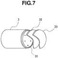
- An LED light-emitting device was constructed as shown in FIG. 7 by placing the two types of wavelength conversion members 32 and 33 on an optical axis and forward of an LED projector 3 including LED chips 31 (LED light source), available as GL-RB100 (having six 2-W blue LED chips XT-E Royal Blue by Cree, Inc.) from Hino Electronic Corp., such that the yellow wavelength conversion member 32 (Y 3 Al 5 O 12 :Ce 3+ phosphor content 5 wt% or Lu 3 Al 5 O 12 :Ce 3+ phosphor content 10 wt%) and the red wavelength conversion member 33 (phosphor content 5 wt% or 10 wt%) were arranged in sequence from the LED projector 3 side.
- LED chips 31 LED light source
- GL-RB100 having six 2-W blue LED chips XT-E Royal Blue by Cree, Inc.
- a light-emitting device was also manufactured in which the red wavelength conversion member 33 was omitted and only the yellow wavelength conversion member 32 (Y 3 Al 5 O 12 :Ce 3+ phosphor content 5 wt% or 10 wt%, or Lu 3 Al 5 O 12 :Ce 3+ phosphor content 10 wt%) was disposed.
- the outer appearance color under white light in the unlit state was measured by a Chroma Meter CR200 (Konica-Minolta Optics Co., Ltd.), evaluated according to CIELAB, and visually observed. The results are shown in Table 2. The outer appearance as visually observed was determined by the wavelength conversion member disposed outermost. The devices of Examples 1 to 3 looked pale yellow whereas the devices of Comparative Examples 1 to 3 looked yellow.
- the LED light-emitting device according to the invention achieves significant improvements in average color rendering index Ra and special color rendering index ⁇ R9 over the LED light-emitting device using only the yellow wavelength conversion member.
- the outside of the light-emitting element in the unlit state looks pale yellow, and as such does not adversely affect the esthetic appearance of the light-emitting device in the unlit state.
- a prior art lamp shade or any obstacle which will adversely affect emission efficiency may be omitted.
Claims (16)
- Wellenlängenumwandlungselement, das ein geformtes thermoplastisches Harz ist, das darin dispergiert einen Leuchtstoff aufweist, der in der Lage ist, Licht mit einer blauen Wellenlängenkomponente zu absorbieren und Licht zu emittieren, das eine rote Wellenlängenkomponente enthält, wobei das Wellenlängenumwandlungselement im nicht emittierenden Zustand eine Farbe aufweist, die als L* = 40 bis 60, a* = 0 bis +1 und b* = +2 bis +15 gemäß CIELAB (CIE 1976) ausgedrückt ist, wobei
der Leuchtstoff ein Fluoridleuchtstoffkomplex ist, nämlich Mangan-aktiviertes Kaliumsilicofluorid der Formel K2(Si1-xMnx)F6, worin x 0,001 bis 0,3 ist, und eine Teilchengrößenverteilung aufweist, in der der 50 % kumulative Volumenbasisteilchendurchmesser D50 von 10 µm bis 40 µm beträgt und eine Farbe in dem nicht emittierenden Zustand als L* = 60 bis 70, a* = +1 bis +3 und b* = +15 bis +30 gemäß CIELAB (CIE 1976) ausgedrückt ist,
wobei der Leuchtstoff in einem Polyolefin als thermoplastisches Harz dispergiert ist und
das Wellenlängenumwandlungselement eine mittlere Dicke von 0,05 bis 5 mm aufweist. - Wellenlängenumwandlungselement nach Anspruch 1, das in Bezug auf Anregungslicht mit einer Wellenlänge von 450 nm eine Lichtdurchlässigkeit von 50 bis 70 % aufweist.
- Wellenlängenumwandlungselement nach einem der vorangegangenen Ansprüche, das ein Lichtstreumittel umfasst.
- Wellenlängenumwandlungselement nach einem der vorangegangenen Ansprüche, wobei das thermoplastische Harz Polypropylen ist.
- Wellenlängenumwandlungselement nach einem der vorangegangenen Ansprüche, wobei das thermoplastische Harz zumindest 40 Gew.-% Polypropylen oder zumindest 40 Gew.-% Polypropylen und Polystyrol umfasst.
- Wellenlängenumwandlungselement nach einem der vorangegangenen Ansprüche, wobei das Wellenlängenumwandlungselement eine Lampenabdeckung, ein Lampenschirm oder ein anderes selbsttragendes Element zur Bereitstellung der äußeren Erscheinungsfarbe einer entfernten, lichtemittierenden Leuchtstoff-Vorrichtung im nicht beleuchteten Zustand ist.
- Wellenlängenumwandlungselement nach einem der vorangegangenen Ansprüche, wobei der Leuchtstoff in einer Menge von 3 bis 15 Gew.-% vorliegt.
- Verfahren zur Herstellung eines Wellenlängenumwandlungselements nach einem der vorangegangenen Ansprüche, wobei das Verfahren Folgendes umfasst:das Auswählen des Fluorid-Leuchtstoffkomplexes;das Dispergieren des Polyolefins mit dem Fluorid-Leuchtstoffkomplex unddas Formen des Gemischs zu einem Wellenlängenumwandlungselement, wobei das Wellenlängenumwandlungselement eine mittlere Dicke von 0,05 bis 5 mm aufweist.
- Lichtemittierende Vorrichtung (10; 10A; 20), die Folgendes umfasst:ein lichtemittierendes Element (11, 12; 11A; 21A), das geeignet ist, um ein pseudoweißes Licht zu emittieren, das eine blaue Wellenlängenkomponente enthält, und eine LED-Lichtquelle (11) umfasst, die in der Lage ist, zumindest blaues Licht zu emittieren, undein Wellenlängenumwandlungselement (13; 23) nach einem der Ansprüche 1 bis 7 oder wie gemäß einem Verfahren nach Anspruch 8 erzeugt, das außerhalb des lichtemittierenden Elements angeordnet ist.
- Lichtemittierende Vorrichtung nach Anspruch 9, die Folgendes umfasst, nacheinander auf der optischen Achse der LED-Lichtquelle (11) ausgehend von der Seite derselben, ein weiteres Wellenlängenumwandlungselement (12) und dann das Wellenlängenumwandlungselement (13; 23),
wobei das weitere Wellenlängenumwandlungselement (12) einen Leuchtstoff enthält, der in der Lage ist, blaues Licht zu absorbieren und ein Licht mit einer anderen Wellenlänge zu emittieren als der Leuchtstoff in dem Wellenlängenumwandlungselement (13; 23) nach einem der Ansprüche 1 bis 7 oder hergestellt gemäß einem Verfahren nach Anspruch 8. - Lichtemittierende Vorrichtung nach Anspruch 10, in der das weitere Wellenlängenumwandlungselement (12) ein Umwandlungselement mit gelber oder grüner Wellenlänge ist.
- Lichtemittierende Vorrichtung nach Anspruch 11, in der der Leuchtstoff in dem weiteren Wellenlängenumwandlungselement (12) Y3Al5O12:Ce3+ ist.
- Lichtemittierende Vorrichtung nach Anspruch 11, in der das weitere Wellenlängenumwandlungselement (12) ein Umwandlungselement mit gelber oder grüner Wellenlänge ist, in dem ein gelber oder grüner Leuchtstoff, wie z.B. Y3Al5O12:Ce3+, Lu3Al5O12:Ce oder (Ba,Sr)2SiO5:Eu2+ in einem thermoplastischen Harz inkorporiert ist.
- Lichtemittierende Vorrichtung nach einem der Ansprüche 9 bis 13, die außerdem eine transparente Schutzabdeckung umfasst, die das Wellenlängenumwandlungselement abdeckt.
- Lichtemittierende Vorrichtung nach einem der Ansprüche 9 bis 14, die eine entfernte, lichtemittierende Leuchtstoff-Vorrichtung ist, in der das Wellenlängenumwandlungselement eine Lampenabdeckung, ein Lampenschirm oder ein anderes selbsttragendes Element zur Bereitstellung der äußeren Erscheinungsfarbe der Vorrichtung im nicht beleuchteten Zustand ist.
- Verfahren zur Herstellung einer lichtemittierenden Vorrichtung nach einem der Ansprüche 9 bis 15, wobei das Verfahren den Schritt des Herstellens eines Wellenlängenumwandlungselements durch ein Verfahren nach Anspruch 8 umfasst.
Applications Claiming Priority (2)
| Application Number | Priority Date | Filing Date | Title |
|---|---|---|---|
| JP2012287426 | 2012-12-28 | ||
| PCT/JP2013/084792 WO2014104155A1 (ja) | 2012-12-28 | 2013-12-26 | 波長変換部材及び発光装置 |
Publications (3)
| Publication Number | Publication Date |
|---|---|
| EP2940747A1 EP2940747A1 (de) | 2015-11-04 |
| EP2940747A4 EP2940747A4 (de) | 2016-07-13 |
| EP2940747B1 true EP2940747B1 (de) | 2020-09-16 |
Family
ID=51021231
Family Applications (1)
| Application Number | Title | Priority Date | Filing Date |
|---|---|---|---|
| EP13869816.2A Active EP2940747B1 (de) | 2012-12-28 | 2013-12-26 | Wellenlängenumwandlungselement und lichtemittierende vorrichtung |
Country Status (7)
| Country | Link |
|---|---|
| US (1) | US9657221B2 (de) |
| EP (1) | EP2940747B1 (de) |
| JP (2) | JPWO2014104155A1 (de) |
| KR (1) | KR102202309B1 (de) |
| CN (1) | CN104919606A (de) |
| TW (1) | TW201444123A (de) |
| WO (1) | WO2014104155A1 (de) |
Families Citing this family (11)
| Publication number | Priority date | Publication date | Assignee | Title |
|---|---|---|---|---|
| JP1523888S (de) * | 2014-08-28 | 2015-05-18 | ||
| US10811572B2 (en) | 2014-10-08 | 2020-10-20 | Seoul Semiconductor Co., Ltd. | Light emitting device |
| JP2016088950A (ja) * | 2014-10-30 | 2016-05-23 | 信越化学工業株式会社 | 赤色蛍光体 |
| CN107002454A (zh) * | 2014-12-04 | 2017-08-01 | 夏普株式会社 | 采光装置 |
| JP6471756B2 (ja) * | 2014-12-09 | 2019-02-20 | 信越化学工業株式会社 | 車載ヘッドライト用led光源 |
| JP6385020B2 (ja) * | 2015-03-09 | 2018-09-05 | シャープ株式会社 | 照明装置、表示装置及びテレビ受信装置 |
| JP6674207B2 (ja) * | 2015-08-06 | 2020-04-01 | ダイトロン株式会社 | 空間光伝送装置 |
| WO2017034355A1 (ko) * | 2015-08-25 | 2017-03-02 | 엘지이노텍 주식회사 | 적색 형광체 및 이를 포함하는 발광장치 |
| WO2017091303A1 (en) * | 2015-11-26 | 2017-06-01 | General Electric Company | Processes for synthesizing red-emitting phosphors and related red-emitting phosphors |
| CN107631272B (zh) * | 2016-07-13 | 2021-08-20 | 深圳光峰科技股份有限公司 | 一种波长转换装置及其制备方法 |
| US10422501B2 (en) * | 2016-12-14 | 2019-09-24 | Ford Global Technologies, Llc | Vehicle lighting assembly |
Family Cites Families (23)
| Publication number | Priority date | Publication date | Assignee | Title |
|---|---|---|---|---|
| JP3956457B2 (ja) * | 1998-01-08 | 2007-08-08 | 日亜化学工業株式会社 | 色変換シート及びそれを用いた発光装置 |
| JP2005244076A (ja) | 2004-02-27 | 2005-09-08 | Matsushita Electric Works Ltd | 発光装置 |
| TWI398188B (zh) | 2004-08-31 | 2013-06-01 | Showa Denko Kk | A luminous body, and a lighting and display device using the luminous body |
| JP2006135002A (ja) | 2004-11-04 | 2006-05-25 | Koito Mfg Co Ltd | 発光デバイス及び車両用灯具 |
| TWI435927B (zh) * | 2006-02-10 | 2014-05-01 | Mitsubishi Chem Corp | 螢光體及其製造方法,含螢光體之組成物,發光裝置,暨影像顯示裝置及照明裝置 |
| TWI438262B (zh) * | 2008-02-07 | 2014-05-21 | Mitsubishi Chem Corp | A semiconductor light emitting device, a backlight, a color image display device, and a phosphor |
| JP5682104B2 (ja) * | 2008-09-05 | 2015-03-11 | 三菱化学株式会社 | 蛍光体及びその製造方法と、その蛍光体を用いた蛍光体含有組成物及び発光装置、並びに、その発光装置を用いた画像表示装置及び照明装置 |
| JP5210109B2 (ja) * | 2008-09-30 | 2013-06-12 | 豊田合成株式会社 | Led発光装置 |
| JP2010171342A (ja) | 2009-01-26 | 2010-08-05 | Sony Corp | 色変換部材およびその製造方法、発光装置、表示装置 |
| JP5506215B2 (ja) * | 2009-03-13 | 2014-05-28 | 住友金属鉱山株式会社 | 蛍光体の製造方法 |
| JP5423120B2 (ja) | 2009-04-17 | 2014-02-19 | 三菱化学株式会社 | 半導体発光装置 |
| JP2010287680A (ja) | 2009-06-10 | 2010-12-24 | Mitsubishi Chemicals Corp | 発光装置 |
| CN102032481B (zh) | 2009-09-25 | 2014-01-08 | 东芝照明技术株式会社 | 附带灯口的照明灯及照明器具 |
| CN102652166B (zh) * | 2009-12-17 | 2015-04-29 | 皇家飞利浦电子股份有限公司 | 具有光源和波长转换元件的照明设备 |
| JP5766411B2 (ja) * | 2010-06-29 | 2015-08-19 | 日東電工株式会社 | 蛍光体層および発光装置 |
| JP2012023288A (ja) * | 2010-07-16 | 2012-02-02 | Nitto Denko Corp | 発光装置用部品、発光装置およびその製造方法 |
| CN103080634B (zh) | 2010-08-31 | 2015-07-22 | 株式会社东芝 | Led电灯泡 |
| JP2012059893A (ja) * | 2010-09-08 | 2012-03-22 | Nippon Electric Glass Co Ltd | 波長変換部材、光源及び波長変換部材の製造方法 |
| JP5549539B2 (ja) * | 2010-10-28 | 2014-07-16 | 日本電気硝子株式会社 | 波長変換素子、それを備える光源及びその製造方法 |
| EP3176839B1 (de) | 2011-03-15 | 2019-07-17 | Kabushiki Kaisha Toshiba | Weisslichtquelle |
| MY161542A (en) | 2011-04-08 | 2017-04-28 | Shinetsu Chemical Co | Preparation of complex fluoride and complex fluoride phosphor |
| JP2012229373A (ja) * | 2011-04-27 | 2012-11-22 | Panasonic Corp | 被覆蛍光体及び発光装置 |
| JP5840540B2 (ja) * | 2012-03-15 | 2016-01-06 | 株式会社東芝 | 白色照明装置 |
-
2013
- 2013-12-26 EP EP13869816.2A patent/EP2940747B1/de active Active
- 2013-12-26 KR KR1020157020278A patent/KR102202309B1/ko active IP Right Grant
- 2013-12-26 JP JP2014554523A patent/JPWO2014104155A1/ja active Pending
- 2013-12-26 CN CN201380068218.4A patent/CN104919606A/zh active Pending
- 2013-12-26 WO PCT/JP2013/084792 patent/WO2014104155A1/ja active Application Filing
- 2013-12-26 US US14/655,533 patent/US9657221B2/en not_active Expired - Fee Related
- 2013-12-27 TW TW102148744A patent/TW201444123A/zh unknown
-
2016
- 2016-06-21 JP JP2016122552A patent/JP6079927B2/ja not_active Expired - Fee Related
Non-Patent Citations (1)
| Title |
|---|
| None * |
Also Published As
| Publication number | Publication date |
|---|---|
| KR20150100891A (ko) | 2015-09-02 |
| EP2940747A4 (de) | 2016-07-13 |
| JP2016200823A (ja) | 2016-12-01 |
| CN104919606A (zh) | 2015-09-16 |
| WO2014104155A1 (ja) | 2014-07-03 |
| EP2940747A1 (de) | 2015-11-04 |
| KR102202309B1 (ko) | 2021-01-14 |
| JP6079927B2 (ja) | 2017-02-15 |
| TW201444123A (zh) | 2014-11-16 |
| JPWO2014104155A1 (ja) | 2017-01-12 |
| US20160002528A1 (en) | 2016-01-07 |
| US9657221B2 (en) | 2017-05-23 |
Similar Documents
| Publication | Publication Date | Title |
|---|---|---|
| EP2940747B1 (de) | Wellenlängenumwandlungselement und lichtemittierende vorrichtung | |
| US9595644B2 (en) | LED lighting arrangement including light emitting phosphor | |
| EP2412038B1 (de) | Beleuchtungsvorrichtung mit einem mit einem entfernt angebrachten leuchtstoffmaterial | |
| EP2940742A1 (de) | Lichtemittierende vorrichtung | |
| EP2940745B1 (de) | Wellenlängenumwandlungselement und lichtemittierende vorrichtung | |
| JP6098747B2 (ja) | 調整部品及び発光装置 |
Legal Events
| Date | Code | Title | Description |
|---|---|---|---|
| PUAI | Public reference made under article 153(3) epc to a published international application that has entered the european phase |
Free format text: ORIGINAL CODE: 0009012 |
|
| 17P | Request for examination filed |
Effective date: 20150703 |
|
| AK | Designated contracting states |
Kind code of ref document: A1 Designated state(s): AL AT BE BG CH CY CZ DE DK EE ES FI FR GB GR HR HU IE IS IT LI LT LU LV MC MK MT NL NO PL PT RO RS SE SI SK SM TR |
|
| AX | Request for extension of the european patent |
Extension state: BA ME |
|
| DAX | Request for extension of the european patent (deleted) | ||
| A4 | Supplementary search report drawn up and despatched |
Effective date: 20160610 |
|
| RIC1 | Information provided on ipc code assigned before grant |
Ipc: C09K 11/77 20060101ALI20160606BHEP Ipc: F21V 3/04 20060101ALI20160606BHEP Ipc: F21V 9/16 20060101ALI20160606BHEP Ipc: C09K 11/66 20060101ALI20160606BHEP Ipc: F21Y 111/00 20160101ALI20160606BHEP Ipc: H01L 33/50 20100101AFI20160606BHEP Ipc: C09K 11/61 20060101ALI20160606BHEP Ipc: F21K 99/00 20160101ALI20160606BHEP Ipc: C09K 11/67 20060101ALI20160606BHEP Ipc: C09K 11/02 20060101ALI20160606BHEP |
|
| STAA | Information on the status of an ep patent application or granted ep patent |
Free format text: STATUS: EXAMINATION IS IN PROGRESS |
|
| 17Q | First examination report despatched |
Effective date: 20180523 |
|
| GRAP | Despatch of communication of intention to grant a patent |
Free format text: ORIGINAL CODE: EPIDOSNIGR1 |
|
| STAA | Information on the status of an ep patent application or granted ep patent |
Free format text: STATUS: GRANT OF PATENT IS INTENDED |
|
| RIC1 | Information provided on ipc code assigned before grant |
Ipc: F21V 3/04 20180101ALI20200130BHEP Ipc: C09K 11/61 20060101ALI20200130BHEP Ipc: C09K 11/77 20060101ALI20200130BHEP Ipc: F21Y 115/10 20160101ALI20200130BHEP Ipc: H01L 33/50 20100101AFI20200130BHEP Ipc: C09K 11/67 20060101ALI20200130BHEP Ipc: F21K 9/64 20160101ALI20200130BHEP Ipc: C09K 11/66 20060101ALI20200130BHEP Ipc: F21Y 107/00 20160101ALI20200130BHEP Ipc: C09K 11/02 20060101ALI20200130BHEP Ipc: F21K 99/00 20160101ALI20200130BHEP Ipc: F21V 9/30 20180101ALI20200130BHEP |
|
| INTG | Intention to grant announced |
Effective date: 20200227 |
|
| GRAJ | Information related to disapproval of communication of intention to grant by the applicant or resumption of examination proceedings by the epo deleted |
Free format text: ORIGINAL CODE: EPIDOSDIGR1 |
|
| STAA | Information on the status of an ep patent application or granted ep patent |
Free format text: STATUS: EXAMINATION IS IN PROGRESS |
|
| GRAR | Information related to intention to grant a patent recorded |
Free format text: ORIGINAL CODE: EPIDOSNIGR71 |
|
| GRAS | Grant fee paid |
Free format text: ORIGINAL CODE: EPIDOSNIGR3 |
|
| STAA | Information on the status of an ep patent application or granted ep patent |
Free format text: STATUS: GRANT OF PATENT IS INTENDED |
|
| INTC | Intention to grant announced (deleted) | ||
| RBV | Designated contracting states (corrected) |
Designated state(s): DE FR NL |
|
| GRAA | (expected) grant |
Free format text: ORIGINAL CODE: 0009210 |
|
| STAA | Information on the status of an ep patent application or granted ep patent |
Free format text: STATUS: THE PATENT HAS BEEN GRANTED |
|
| INTG | Intention to grant announced |
Effective date: 20200710 |
|
| AK | Designated contracting states |
Kind code of ref document: B1 Designated state(s): DE FR NL |
|
| REG | Reference to a national code |
Ref country code: DE Ref legal event code: R096 Ref document number: 602013072656 Country of ref document: DE |
|
| REG | Reference to a national code |
Ref country code: NL Ref legal event code: FP |
|
| REG | Reference to a national code |
Ref country code: DE Ref legal event code: R097 Ref document number: 602013072656 Country of ref document: DE |
|
| PLBE | No opposition filed within time limit |
Free format text: ORIGINAL CODE: 0009261 |
|
| STAA | Information on the status of an ep patent application or granted ep patent |
Free format text: STATUS: NO OPPOSITION FILED WITHIN TIME LIMIT |
|
| 26N | No opposition filed |
Effective date: 20210617 |
|
| PGFP | Annual fee paid to national office [announced via postgrant information from national office to epo] |
Ref country code: NL Payment date: 20231116 Year of fee payment: 11 |
|
| PGFP | Annual fee paid to national office [announced via postgrant information from national office to epo] |
Ref country code: FR Payment date: 20231108 Year of fee payment: 11 Ref country code: DE Payment date: 20231031 Year of fee payment: 11 |