EP2939787A2 - Verfahren zum bearbeiten einer glasscheibe und glasscheibenbearbeitungsvorrichtung - Google Patents
Verfahren zum bearbeiten einer glasscheibe und glasscheibenbearbeitungsvorrichtung Download PDFInfo
- Publication number
- EP2939787A2 EP2939787A2 EP15164904.3A EP15164904A EP2939787A2 EP 2939787 A2 EP2939787 A2 EP 2939787A2 EP 15164904 A EP15164904 A EP 15164904A EP 2939787 A2 EP2939787 A2 EP 2939787A2
- Authority
- EP
- European Patent Office
- Prior art keywords
- glass
- robot
- processing
- coupling
- glass pane
- Prior art date
- Legal status (The legal status is an assumption and is not a legal conclusion. Google has not performed a legal analysis and makes no representation as to the accuracy of the status listed.)
- Granted
Links
Images


Classifications
-
- B—PERFORMING OPERATIONS; TRANSPORTING
- B24—GRINDING; POLISHING
- B24B—MACHINES, DEVICES, OR PROCESSES FOR GRINDING OR POLISHING; DRESSING OR CONDITIONING OF ABRADING SURFACES; FEEDING OF GRINDING, POLISHING, OR LAPPING AGENTS
- B24B9/00—Machines or devices designed for grinding edges or bevels on work or for removing burrs; Accessories therefor
- B24B9/02—Machines or devices designed for grinding edges or bevels on work or for removing burrs; Accessories therefor characterised by a special design with respect to properties of materials specific to articles to be ground
- B24B9/06—Machines or devices designed for grinding edges or bevels on work or for removing burrs; Accessories therefor characterised by a special design with respect to properties of materials specific to articles to be ground of non-metallic inorganic material, e.g. stone, ceramics, porcelain
- B24B9/08—Machines or devices designed for grinding edges or bevels on work or for removing burrs; Accessories therefor characterised by a special design with respect to properties of materials specific to articles to be ground of non-metallic inorganic material, e.g. stone, ceramics, porcelain of glass
- B24B9/10—Machines or devices designed for grinding edges or bevels on work or for removing burrs; Accessories therefor characterised by a special design with respect to properties of materials specific to articles to be ground of non-metallic inorganic material, e.g. stone, ceramics, porcelain of glass of plate glass
-
- B—PERFORMING OPERATIONS; TRANSPORTING
- B24—GRINDING; POLISHING
- B24B—MACHINES, DEVICES, OR PROCESSES FOR GRINDING OR POLISHING; DRESSING OR CONDITIONING OF ABRADING SURFACES; FEEDING OF GRINDING, POLISHING, OR LAPPING AGENTS
- B24B27/00—Other grinding machines or devices
- B24B27/0069—Other grinding machines or devices with means for feeding the work-pieces to the grinding tool, e.g. turntables, transfer means
-
- B—PERFORMING OPERATIONS; TRANSPORTING
- B24—GRINDING; POLISHING
- B24B—MACHINES, DEVICES, OR PROCESSES FOR GRINDING OR POLISHING; DRESSING OR CONDITIONING OF ABRADING SURFACES; FEEDING OF GRINDING, POLISHING, OR LAPPING AGENTS
- B24B27/00—Other grinding machines or devices
- B24B27/0076—Other grinding machines or devices grinding machines comprising two or more grinding tools
-
- B—PERFORMING OPERATIONS; TRANSPORTING
- B24—GRINDING; POLISHING
- B24B—MACHINES, DEVICES, OR PROCESSES FOR GRINDING OR POLISHING; DRESSING OR CONDITIONING OF ABRADING SURFACES; FEEDING OF GRINDING, POLISHING, OR LAPPING AGENTS
- B24B41/00—Component parts such as frames, beds, carriages, headstocks
- B24B41/005—Feeding or manipulating devices specially adapted to grinding machines
-
- B—PERFORMING OPERATIONS; TRANSPORTING
- B24—GRINDING; POLISHING
- B24B—MACHINES, DEVICES, OR PROCESSES FOR GRINDING OR POLISHING; DRESSING OR CONDITIONING OF ABRADING SURFACES; FEEDING OF GRINDING, POLISHING, OR LAPPING AGENTS
- B24B41/00—Component parts such as frames, beds, carriages, headstocks
- B24B41/06—Work supports, e.g. adjustable steadies
-
- B—PERFORMING OPERATIONS; TRANSPORTING
- B61—RAILWAYS
- B61D—BODY DETAILS OR KINDS OF RAILWAY VEHICLES
- B61D3/00—Wagons or vans
- B61D3/16—Wagons or vans adapted for carrying special loads
- B61D3/18—Wagons or vans adapted for carrying special loads for vehicles
- B61D3/182—Wagons or vans adapted for carrying special loads for vehicles specially adapted for heavy vehicles, e.g. public work vehicles, trucks, trailers
- B61D3/184—Wagons or vans adapted for carrying special loads for vehicles specially adapted for heavy vehicles, e.g. public work vehicles, trucks, trailers the heavy vehicles being of the trailer or semi-trailer type
-
- B—PERFORMING OPERATIONS; TRANSPORTING
- B61—RAILWAYS
- B61D—BODY DETAILS OR KINDS OF RAILWAY VEHICLES
- B61D47/00—Loading or unloading devices combined with vehicles, e.g. loading platforms, doors convertible into loading and unloading ramps
- B61D47/005—Loading or unloading devices combined with road vehicles carrying wagons, e.g. ramps, turntables, lifting means
Definitions
- the invention relates to a method for processing a glass sheet.
- the invention relates to a glass processing apparatus for processing a glass pane with (a) a robot and (b) at least one processing apparatus for processing the glass pane.
- the US 6,099,385 describes a generic method for separating protruding plastic remnants of a laminated car window by means of grinding wheels. This method is also unsuitable for the processing of large glass panes or the processing of the edge with several grinding devices.
- the invention has for its object to improve the surface quality and manufacturing speed in the production of glass.
- the invention solves the problem by a method having the features of claim 1. According to a second aspect, the invention solves the problem by a glass processing apparatus having the features of claim 3.
- An advantage of the invention is that several machining operations can be performed sequentially without the robot has to let go of the disc.
- glass or diamond particles produced during the machining process can hardly get between two components of the glass processing machine which are to be moved relative to one another, which avoids the formation of scratches. It has been found that when rewinding the glass sheets, which is inevitable in the production of the prior art, even with thorough washing of the glass glass or diamond particles get between the glass and the holding device and can cause small scratches. Since in the invention can be dispensed with a re-clamping, scratches can no longer arise in this way.
- Another advantage of the invention is that can be easily run down by the upright holding the glass pane if any inserted cooling lubricant. In this way, very few potentially scratch-causing particles adhere to the glass pane. In addition, there is no or only a slight deflection, which significantly reduces the probability of breakage.
- machining is understood to mean machining according to DIN 8589, which is preferably machining with a geometrically indefinite cutting edge, in particular grinding.
- a robot is to be understood in particular as a positioning machine with at least five, preferably six, particularly preferably seven axes. It is particularly favorable if at least one of these axes is a linear axis by means of which the robot can be moved in a longitudinal direction.
- the glass pane can be positioned to a predetermined position in space.
- the position is understood to mean the entirety of the position and of the inclination, wherein the position can be described by three Cartesian coordinates and the inclination by one, two or three angles with respect to the coordinate system.
- the glass sheet with the vertical forms an angle of at most 45 °, in particular at most 20 °, preferably at most 10 °.
- the angle is calculated as the angle between the plane along which the glass sheet extends on the one hand and the perpendicular on the other. The angle should be as small as possible.
- the robot is set up for frictionally holding the glass pane.
- the glass pane is held, for example, by a suction element, which is arranged at a distance from the edge of the glass pane.
- the glass sheet is substantially not resting on a part of the robot, by which it is understood that while it is possible that the glass sheet rests on a part of the robot, but that at least 85% of the weight of the glass sheet is received via a frictional connection ,
- the glass sheet is for machining moved by a robot on a stationary processing device along.
- This is understood to mean that the processing device remains in the same place as a unit, with parts of the processing device being able to move naturally.
- the processing device is, for example, a grinding device, a polishing device or a water jet cutting device. It is possible, but not necessary, for the robot alone to effect the relative movements between the glass sheet and the processing device. It is also possible that in addition to the robot, the processing device moves.
- the linear conveyor on a first rotating conveyor element and a second rotating conveyor element, wherein the glass pane between the two conveying elements frictionally secured, in particular clamped.
- the frictional fastening can be a clamping or suction.
- the robot and the linear conveyor are synchronized with each other, in particular, it is understood that the robot and the linear conveyor convey the glass sheet at the same speed. At the same speed, it is understood in particular that small speed differences are possible, but they are so small that there is no relative movement between the glass pane and the holding element of the robot and / or the glass pane and the conveying elements at the point of contact between the two.
- the robot predominantly holds the disk, that is to say it absorbs at least 50% of the weight of the glass pane, the linear conveyor guiding the glass pane so that it is positioned sufficiently precisely relative to the processing apparatus even when the process forces acting during the machining process are applied.
- the robot holds at least 80% of the weight, in particular at least 90%.
- the robot holds the disk alone, which means that it absorbs 100% of the weight.
- the processing takes place at a lower edge of the glass sheet.
- This has the advantage that cooling lubricant and / or chips can fall down and little pollute the rest of the glass.
- the glass sheet is attached adjacent to its lower edge on the linear conveyor.
- the processing device comprises at least one grinding device for grinding an edge of the glass pane and at least one polishing device for polishing the edge of the glass pane.
- the at least one grinding device and the at least one polishing device are arranged side by side for grinding and polishing in one pass along the linear conveyor.
- the grinding device comprises a chamfering device for chamfering the glass sheet and / or straight-line grinding of the edge.
- the processing device has a plurality of grinding devices and a plurality of polishing devices.
- This has the advantage that a straight edge of the glass pane can be finished by moving the glass pane along the at least one grinding device and the at least one polishing device by means of the robot, preferably by means of the robot and the linear conveyor.
- a linear conveyor vibrations occurring during grinding and polishing are recorded, so that a high quality machining is achieved.
- the glass processing apparatus comprises a rail, wherein the robot is movable on the rail.
- the robot is movable on the rail. This makes it possible to equip the robot with a relatively short arm and still be able to process long edges of a glass pane.
- a linear axis of the robot is considered as containing a rail.
- the glass processing apparatus comprises at least a second robot, which is movably guided on the same rail as the first robot.
- This increases the achievable productivity. It is favorable if the rail forms at least one closed track. This allows the robots along the closed Rail in always the same passage direction to drive.
- the processing of a second glass pane can be started when the first glass pane is still being processed, without the glass pane having to be transferred from one of the robots to another robot or another handling device.
- the glass processing apparatus comprises a drilling grinder having a spindle having a coupling structure, a set of tool heads and a gripper, each tool head having a centering cone and a coupling structure for positive engagement with the coupling structure and for magnetic coupling with the Spindle is formed and wherein the gripper has holding rollers which are rotatably mounted and by means of which a tool head with respect to a movement in the axial direction of the tool head is durable.
- this glass processing device additionally has the above-mentioned properties.
- An independent subject of the invention is a glass processing apparatus for processing a glass sheet, comprising (a) a robot, (b) at least one processing apparatus for processing the glass sheet, and (c) a drill grinding apparatus comprising (i) a spindle having a coupling structure, ( ii) a set of tool heads, each tool head having a centering cone and a coupling structure for positive engagement with the coupling structure and adapted for magnetic coupling with the spindle, and (iii) a gripper having support rollers rotatably supported and by means of a tool head with respect to a movement in the axial direction of the tool head is durable.
- a drill grinding apparatus comprising (i) a spindle having a coupling structure, ( ii) a set of tool heads, each tool head having a centering cone and a coupling structure for positive engagement with the coupling structure and adapted for magnetic coupling with the spindle, and (iii) a gripper having support rollers rotatably supported and by
- Bohrschleifvorraum which is a special grinding device
- Another advantage is the simple design of the tool heads, which makes them very robust.
- the coupling structure and the coupling structure are formed so that when moving the tool head and spindle in the axial direction with respect to a rotational axis of the spindle toward each other either the tool head and the spindle without rotation about the axis of rotation form-fitting coupled or torque is generated, so that the tool head rotates about the axis of rotation and the tool head then couples with the spindle.
- the coupling structure and / or the coupling-in structure have a chamfer and have a radius of curvature that is so large in a plane perpendicular to the axis of rotation that the respective object always strikes a flank, except in theoretical limiting cases, so that a torque with respect to one Rotation about the axis of rotation is generated.
- the coupling-in structure and / or the coupling structure have a quasi-rotational symmetry.
- the coupling structure and / or the coupling structure have only approximately rotationally symmetrical shape.
- the coupling-in structure or the coupling structure has a quasi-rotational symmetry and the respective other structure has a strict rotational symmetry.
- the robot comprises a holding device, wherein the holding device has a first holding element, which is fastened by means of a connection to the robot, at least one first suction element, which is acted upon by the connection with a fluid pressure for holding the glass pane, and has a first coupling element, and has a second holding element for fixing to the first holding element, wherein the second holding element has at least a second suction element, by means of which the glass pane can be held, and a second coupling element, and by means of the second coupling element with the first coupling element automatically is rigidly connected so that the second suction element is actuated by means of the fluid. It results in such a variable in size gripper.
- An independent object of the invention is a glass processing apparatus for processing a glass sheet, comprising (a) a robot and (b) at least one processing device for processing the glass sheet, the robot having a holding device, wherein the holding device comprises a first holding element, which by means of a connection on Robot is attached, at least a first suction element, which is acted upon via the connection with a fluid pressure for holding the glass pane, and having a first coupling element, and a second holding element for fixing to the first holding element, wherein the second holding element has at least a second suction element , by means of which the glass pane can be held, and has a second coupling element, and by means of the second coupling element with the first coupling element is automatically rigidly connectable so that the second suction element is actuated by means of the fluid. It results in such a variable in size gripper.
- the holder is advantageous because the glass processing device according to the invention is preferably used for the production of glass sheets at very small lot sizes, in particular lot size 1. On the one hand, it is necessary to hold each pane of glass securely. On the other hand, the gripper should only attack at locations spaced from the edge of the glass pane in order to allow processing of all edges without grasping.
- the robot can modify the gripper so that it optimally meets the requirements before processing each glass pane.
- the holding elements are connected rigidly to one another in such a way that the load of the glass pane, which is received by the second holding element, can be introduced via the first holding element into the arm of the robot holding the first holding element.
- the suction element can be acted upon by a fluid pressure
- an overpressure or a negative pressure can be applied.
- the suction element may be a vacuum suction device, which sucks and holds the glass pane by means of the at least one suction element.
- This negative pressure can be generated by applying a negative pressure via the connection.
- an overpressure is applied, for example by means of compressed air, and that the negative pressure is generated by means of a Venturi nozzle.
- the second suction element can be actuated by means of the fluid pressure
- the first holding element and the second holding element can be connected by means of the coupling elements such that the vacuum for actuating the suction elements can be transferred from the first holding element to the second holding element.
- at least the first coupling element is preferably designed for opening a vacuum line when the second coupling element is coupled, and for closing this vacuum line, when the second coupling element is not connected.
- it is sufficient to supply a vacuum via the connection on the robot, by means of which both the first suction element and the second suction element can be actuated.
- Each of the suction members may be constructed of a plurality of partial suction members to increase the suction force and grip safety of the holder.
- the holding device has at least a third holding element which has at least a third suction element, by means of which the glass pane can be held, and which has a third coupling element, wherein the third coupling element with the first coupling element and / or the second coupling element is automatically rigidly connected, so that the third suction element is actuated by means of the fluid.
- the glass processing device has at least a fourth holding element, which has at least a fourth suction element, by means of which the glass pane can be held, and which has a fourth coupling element, wherein the fourth coupling element with the first coupling element and / or the second coupling element and / or the third Coupling element is automatically rigidly connected to each other so that the third suction element is actuated by means of the fluid.
- the first retaining element has at least one further coupling element, and in particular has two, three, four or more coupling elements.
- the second holding element and - if present - further holding elements can be coupled at several positions, which increases the configurability of the holding device.
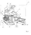
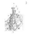
- FIG. 1 shows a glass processing apparatus 10 according to the invention, which has a robot 12 and a first processing device 14.
- the robot 12 has a base 15, a base body 16 fixed to the base 15, a first arm 18 pivotally attached to the base 16, a second arm 20 fixed to the first arm 18, and a head 22 attached to the second arm 20 is attached.
- the robot 12 comprises a holding device 24 in the form of a suction gripper for non-positive Holding a glass pane 26.
- FIG. 1 shows that the first processing device 14 includes a drill sharpener 13 having two opposing-side tool heads 44.1, 44.2 in the form of drill heads.
- Each tool head 44 (reference numerals without counting suffix refer to all corresponding objects) is rotationally driven by means of a spindle 46.1 or 46.2 and is delivered in such a way that the resulting force on the glass pane 26 is minimized.
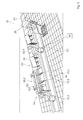
- FIG. 2 shows a partial perspective view of a glass processing apparatus according to the invention 10 according to a second embodiment.
- the processing device 14 comprises a first grinding device 48, in the present case in the form of a belt grinder, and a second grinding device 50, which are arranged for processing a lower edge 52 of the glass pane 26.
- the processing device 14 also includes further grinding devices, which in the view according to FIG. 2 not completely visible.
- the glass processing apparatus 10 has a linear conveyor 28, which has a first circulating conveying element 30 in the form of a pressure chain. Opposite the first conveying element 30, a second conveying element 32 is arranged. By means of the two conveying elements 30, 32, the glass sheet 26 can be held by clamping and / or fixed with respect to a horizontal plane H. It can be seen that the first processing device 14 is arranged below the conveying elements 30, 32.
- the glass processing apparatus 10 has a rail 34 on which the robot 12 is movably guided.
- the base 15 is guided on the rail 34 in the present case.
- the robot 12 is a seven-axis robot whose seventh axis is the rail 34.
- the rail 34 which is a preferred embodiment, runs parallel to a longitudinal direction L of the linear conveyor 28. This longitudinal direction L is the direction in which the glass sheet 26 is conveyed by the linear conveyor 28.
- the robot 12 and the linear conveyor 28 are synchronized with each other. In the present case, this is done by the robot 12 and the linear conveyor 28 being connected to a control unit 36 by cable or by radio.
- the robot 12 For threading the glass sheet 26 between the two conveying elements 30, 32, the robot 12 holds the glass sheet 26 upright and moves it at a predetermined disk speed v 12 between the two conveying elements 30, 32, which are moved at a conveying speed v 28 .
- the conveying speed v 28 is preset so that it corresponds to the disk speed v 12 .
- a force which acts between the robot 12 and the linear conveyor 28.
- the glass sheet 26 has a weight force G, which is taken in the present case to 100% by the robot 12.
- G is taken in the present case to 100% by the robot 12.
- the linear conveyor 28 can accommodate part of the weight, but is particularly favorable when the linear conveyor 28 is only the lateral stabilization, in the present case, a stabilization in the x-y plane.
- FIG. 3 shows a front view of the linear conveyor 28.
- a first motor 38 in the present case in the form of a geared motor for driving the first conveyor element 30 and a second motor 40 for driving a second conveyor element 32. Both motors 38, 40 are connected to the drive unit 36th (please refer FIG. 1 ) and speed variable, so that the conveying speed v 28 is adjustable.
- the first conveying element 30 has a biasing unit 42, by means of which a clamping force, which exert the conveying elements on the glass pane can be adjusted. In this way, glass panes of different thicknesses can be processed.
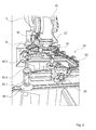
- FIG. 4 shows an advanced processing apparatus 14 which also has a first polishing apparatus 54, a second polishing apparatus 56, a fine polishing apparatus 58, and a super polishing apparatus 60. If the glass pane 26 is guided once with the wheel speed v 12 along the processing device 14, the lower edge 52 is finished.
- FIG. 4 also shows a feed unit 62, by means of a gap between the two conveying elements 30, 32 (see. FIG. 3 ) is adjustable. With the devices 54, 56, 58, 60, 62, the lower edge 52 is processed.
- the first grinding device 48 and the second grinding device 50 belong to a seam processing device, by means of which the glass sheet is chamfered.
- To hem processing device includes two other tailing devices that in FIG. 4 not completely visible.
- FIG. 5 shows a glass processing apparatus 10, which includes two robots 12.1., 12.2, which run together on the rail 34.
- the processing device 14 comprises a first unit 65.1, the structure of which in FIG. 2 is shown, and a second unit 65.2 having a structure as in FIG. 1 may have shown. Between the two units 65.1, 65.2 is in this case a transfer station 63, on which one or more glass panes 26 can be turned off. It is thus possible and within the scope of a preferred embodiment of a method according to the invention to provide that a first robot 12.1 aligns a glass pane 26, for example from a bearing 61, by means of an alignment unit 67 and then feeds it to the first unit 65.1 of the processing apparatus 14.
- the glass pane 26 is processed. Subsequently, the first robot 12.1, the glass on the transfer station 63 from. The second robot 12. 2 grips the glass pane 26 and supplies it to the second unit 65. 2 of the processing device 14.
- the first robot 12.1 first supplies the glass pane to the first unit 65.1 and then to the second unit 65.2.
- FIG. 5 shows that the rail 34 has two Bohrschleifvoriques 13 has two Bohrschleifticianen 13.1, 13.2.
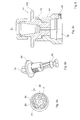
- FIG. 6 shows in its part FIG. 6a a spindle head 64 of the spindle 46.1 (see. FIG. 1 ).
- the spindle head 46 has a coupling-in structure 66, which in the present case has a hexagonal rotational symmetry.
- An end face 68 of the coupling structure 66 has a chamfer 70.
- the chamfer 70 extends inclined to a plane E, which is perpendicular to a rotational axis of the spindle 46.1, along a curve whose radius of curvature is greater than 1 mm. This allows easy coupling.
- FIG. 4b and 4c 2 show a tool head 44 which has a centering cone 72 and a coupling structure 74 which engage with the coupling-in structure 66 (FIG. FIG. 6a ) cooperates positively.
- the tool head 44 On a side remote from the coupling structure 74, the tool head 44 has a processing section 76 for processing the glass pane.
- FIG. 6c shows a cross section through the spindle head 64 and the tool head 44. It can be seen that the spindle head 46 is fixed to a spindle shaft 78 of the spindle, in the present case by means of a countersunk screw 80th
- FIG. 7 shows a gripper 100, the part of a tool changer 102 (see. FIG. 5 ).
- the tool changer 102 is designed in the present case as a robot and in turn part of the Bohrschleifvorraum 13, which in turn is part of the processing device 14.
- the gripper 100 has per gripper unit 102 each three retaining rollers 104, of which the retaining rollers 104.1 and 104.2 in FIG. 7 you can see.
- the three retaining rollers 104 are arranged, for example, in equidistant angular increments about a longitudinal axis of the gripper L 100 , so that the third retaining roller in the sectional view according to FIG FIG. 7 not visible.
- the holding rollers 104 are rotatable about respective axes of rotation D and each have a groove 106.
- the support rollers 104 are ball bearings.
- the groove 106 is designed so that a coupling projection 108 of the tool head 44 can be gripped in a form-fitting manner. In other words, it comes to a positive connection between the coupling projection 108 and the groove 106.
- the tool head 44 In the coupled state, the tool head 44 can be withdrawn by a movement along the gripper longitudinal axis L 100 of the schematically indicated by dashed lines 46 spindle.
- the retaining rollers 104 are attached to a respective gripper arm 110. At least one of the gripper arms, but preferably two or three of the gripper arms, can be moved radially outward by a motor. In the present case, the gripper arms are moved pneumatically outwards. By a radial outward movement of the coupling projection 108 is disengaged from the grooves 106, so that the tool head 44 can be removed.
- the tool head 104 can rotate freely. This is advantageous if the coupling structure 74 (cf. Fig. 4b ) angularly displaced to the coupling structure 66 ( FIG. 6a ) is arranged when the tool head 44 is inserted into the spindle head 64 with the gripper 100. Then the tool head turns automatically into the correct angular position.
- the gripper arms 110 are formed on a first gripping unit 112.1.
- the gripper 100 has two, three or more gripping units 112, wherein three gripping units are particularly preferred. It is then possible, first with the empty gripping unit 112.1 to release a tool head from the spindle 46, by rotating the gripper 100 about a rotation axis D 100 a second, equipped with another tool head 44 Position gripper unit 112 in front of the spindle and then insert the new tool head into the spindle. Thereafter, another drilling grinding device, for example, the Bohrschleifvorraum 13.2 (see. Fig. 3c ) and there also the tool head to be changed.
- another drilling grinding device for example, the Bohrschleifvorraum 13.2 (see. Fig. 3c ) and there also the tool head to be changed.
- FIG. 8 shows the holding device 24, which has a first holding element 82 which is fastened by means of a connection 84 to the head 22 of the robot.
- the first holding element 82 comprises a plurality of first suction elements 86.1, 86.2,..., Which can be supplied with vacuum via the connection 84, which vacuum is provided via a vacuum line 88 of the robot 12.
- the first holding element 82 also includes a first coupling element 90.
- FIG. 9 shows a second retaining element 92, the second suction elements 94.1, 94.2, 94.3 includes and has a second coupling element 96.
- the second coupling element 96 is rigidly connected to the first coupling element 90 and connected to transmit the vacuum.
- the robot 12.1 (see FIG. 5 Depending on the size of the glass pane 26, the robot 12 moves the first holding element 82 to the second holding element 92 or a third, fourth or fifth holding element and couples one, two or more holding elements together in that the holding device 24 is sufficiently large to hold the glass pane 26 securely and is sufficiently small to allow complete processing without grasping.
- the robot 12 grips the glass plate 26 and introduces it into the linear conveyor as described above.
- the drive unit 36 transmits to the robot the trajectory along which the glass pane 26 is to be moved.
- the drive unit 36 of the processing device 14 transmits the processing parameters for processing the glass pane.
- the robot 12 sets the glass on a transport device.
Abstract
Description
- Die Erfindung betrifft ein Verfahren zum Bearbeiten einer Glasscheibe. Gemäß einem zweiten Aspekt betrifft die Erfindung eine Glasbearbeitungsvorrichtung zum Bearbeiten einer Glasscheibe mit (a) einem Roboter und (b) zumindest einer Bearbeitungsvorrichtung zum Bearbeiten der Glasscheibe.
- Bei der Fertigung von Glasscheiben müssen in der Regel eine Reihe an Fertigungsschritten durchgeführt werden. So muss zunächst ein Rohling aus einer Standard-Scheibe herausgebrochen werden. Dieser Rohling muss danach gegebenenfalls an den Kanten nachbearbeitet werden. In der Regel wird die Glasscheibe danach am Rand geschliffen und gesäumt und möglicherweise poliert. Nach dem Stand der Technik werden Glasscheiben von spezialisierten Automaten in Fließbandanordnung bearbeitet, die jeweils einen Arbeitsschritt durchführen, so dass eine hohe Produktivität erreicht werden kann.
- Es hat sich jedoch herausgestellt, dass höchste Oberflächenqualitäten insbesondere in Bezug auf die Fläche der Glasscheibe, durch die hindurchgeblickt wird, auf diese Weise nur schlecht zu erreichen sind.
- Aus der
DE 10 2008 027 050 A1 und derUS 7,056,191 B2 sind gattungsgemäße Verfahren und Vorrichtungen zum automatischen Kantenschleifen von Glasplatten für die Fertigung von Solarmodulen bekannt, wobei die Glasplatte mittels eines Roboters gehalten und an einem Schleifaggregat vorbeigeführt wird. Nachteilig daran ist, dass eine Bearbeitung großer Glasscheiben oder das Bearbeiten der Kante mit mehreren Schleifvorrichtungen wenig prozesssicher ist. - Die
US 6,099,385 beschreibt ein gattungsgemäßes Verfahren zum Abtrennen überstehender Kunststoffreste eines laminierten Autofensters mittels Schleifscheiben. Auch dieses Verfahren ist für die Bearbeitung großer Glasscheiben oder das Bearbeiten der Kante mit mehreren Schleifvorrichtungen wenig geeignet. - Der Erfindung liegt die Aufgabe zugrunde, die Oberflächenqualität und Fertigungsgeschwindigkeit bei der Fertigung von Glasscheiben zu verbessern.
- Die Erfindung löst das Problem durch ein Verfahren mit den Merkmalen von Anspruch 1. Gemäß einem zweiten Aspekt löst die Erfindung das Problem durch eine Glasbearbeitungsvorrichtung mit den Merkmalen von Anspruch 3.
- Vorteilhaft an der Erfindung ist, dass mehrere spanende Bearbeitungsschritte nacheinander durchgeführt werden können, ohne dass der Roboter die Scheibe loslassen muss. Das führt dazu, dass bei der spanenden Bearbeitung entstehende Glas- oder Diamantpartikel kaum zwischen zwei sich relativ zueinander zu bewegende Komponenten der Glasbearbeitungsmaschine gelangen können, was die Bildung von Kratzern vermeidet. Es hat sich nämlich herausgestellt, dass beim Umspannen der Glasscheiben, das bei der Fertigung nach dem Stand der Technik unvermeidlich ist, auch bei gründlichem Waschen der Glasscheibe Glas- oder Diamantpartikel zwischen die Glasscheibe und die Haltevorrichtung gelangen und kleine Kratzer hervorrufen können. Da bei der Erfindung auf ein Umspannen verzichtet werden kann, können auf diese Weise keine Kratzer mehr entstehen.
- Auch ist vorteilhaft, dass eine Bearbeitung, bei der nur wenige Aggregate eingesetzt werden müssen, schneller durchführbar ist als bei Verwendung einer Fließbandfertigung.
- Vorteilhaft an der Erfindung ist zudem, dass durch das aufrechte Halten der Glasscheibe etwaig eingesetzter Kühlschmierstoff leicht nach unten ablaufen kann. Auf diese Weise haften besonders wenige potentiell Kratzer verursachende Partikel an der Glasscheibe. Zudem kommt es zu keiner oder nur einer geringen Durchbiegung, was die Bruchwahrscheinlichkeit deutlich verringert.
- Im Rahmen der vorliegenden Beschreibung wird unter einer spanenden Bearbeitung die Bearbeitung gemäß DIN 8589 verstanden, wobei es sich vorzugsweise um ein Spanen mit geometrisch unbestimmter Schneide, insbesondere ein Schleifen, handelt.
- Unter einem Roboter wird insbesondere eine positionierende Maschine mit zumindest fünf, vorzugsweise sechs, besonders bevorzugt sieben Achsen verstanden. Besonders günstig ist es, wenn zumindest eine dieser Achsen eine Linearachse ist, mittels der der Roboter in einer Längsrichtung bewegbar ist. Mittels eines Roboters kann die Glasscheibe auf eine vorgegebene Position im Raum positioniert werden. Unter der Position wird dabei die Gesamtheit aus der Lage und der Neigung verstanden, wobei die Lage durch drei kartesische Koordinaten beschreibbar ist und die Neigung durch ein, zwei oder drei Winkel bezüglich des Koordinatensystems.
- Unter dem Merkmal, dass die Glasscheibe aufrecht gehalten wird, wird insbesondere verstanden, dass die Glasscheibe mit der Vertikalen einen Winkel von höchstens 45°, insbesondere höchstens 20°, bevorzugt höchstens 10°, bildet. Der Winkel wird berechnet als der Winkel zwischen der Ebene, entlang der sich die Glasscheibe erstreckt einerseits und der Lotrechten andererseits. Der Winkel sollte betragsmäßig möglichst klein sein.
- Bevorzugt ist der Roboter eingerichtet zum reibschlüssigen Halten der Glasscheibe. In anderen Worten wird die Glasscheibe - beispielsweise von einem Saugelement - gehalten, das vom Rand der Glasscheibe beabstandet angeordnet ist. Vorzugsweise liegt die Glasscheibe im Wesentlichen nicht auf einem Teil des Roboters auf, worunter zu verstehen ist, dass es zwar möglich ist, dass die Glasscheibe auf einem Teil des Roboters aufliegt, dass aber zumindest 85% der Gewichtskraft der Glasscheibe über eine reibschlüssige Verbindung aufgenommen wird.
- Gemäß einer bevorzugten Ausführungsform wird die Glasscheibe zum spanenden Bearbeiten mittels des Roboters an einer stehenden Bearbeitungsvorrichtung entlang bewegt. Hierunter ist zu verstehen, dass die Bearbeitungsvorrichtung als Einheit am Platze bleibt, wobei sich Teile der Bearbeitungsvorrichtung bewegen selbstverständlich können.
- Bei der Bearbeitungsvorrichtung handelt es sich beispielsweise um eine Schleifvorrichtung, eine Poliervorrichtung oder eine Wasserstrahl-Schneidvorrichtung. Es ist möglich, nicht aber notwendig, dass der Roboter allein die Relativbewegungen zwischen der Glasscheibe und der Bearbeitungsvorrichtung bewirkt. Es ist auch möglich, dass sich zusätzlich zum Roboter auch die Bearbeitungsvorrichtung bewegt.
- Vorzugsweise weist der Linearförderer ein erstes umlaufendes Förderelement und ein zweites umlaufendes Förderelement auf, wobei die Glasscheibe zwischen den beiden Förderelementen reibschlüssig befestigt, insbesondere geklemmt wird. Das reibschlüssige Befestigen kann ein Klemmen oder auch ein Ansaugen sein.
- Unter dem Merkmal, dass der Roboter und der Linearförderer miteinander synchronisiert werden, wird insbesondere verstanden, dass der Roboter und der Linearförderer die Glasscheibe mit der gleichen Geschwindigkeit transportieren. Unter der gleichen Geschwindigkeit wird dabei insbesondere verstanden, dass geringe Geschwindigkeitsunterschiede möglich sind, diese aber so gering sind, dass es zu keiner Relativbewegung zwischen der Glasscheibe und dem Halteelement des Roboters und/oder der Glasscheibe und den Förderelementen im Kontaktpunkt zwischen beiden kommt.
- Insbesondere hält überwiegend der Roboter die Scheibe, das heißt er nimmt zumindest 50% der Gewichtskraft der Glasscheibe auf, wobei der Linearförderer die Glasscheibe so führt, dass sie auch beim Einwirken der bei der spanenden Bearbeitung wirkenden Prozesskräfte hinreichend genau relativ zu der Bearbeitungsvorrichtung positioniert ist. Vorzugsweise hält der Roboter zumindest 80% der Gewichtskraft, insbesondere zumindest 90%. In der Regel hält der Roboter die Scheibe allein, das heißt, dass er 100% der Gewichtskraft aufnimmt.
- Vorzugsweise erfolgt die Bearbeitung an einer Unterkante der Glasscheibe. Das hat den Vorteil, dass Kühlschmierstoff und/oder Späne nach unten fallen und den Rest der Glasscheibe wenig verschmutzen können. Vorzugsweise ist die Glasscheibe benachbart zu ihrer Unterkante am Linearförderer befestigt.
- Vorzugsweise umfasst die Bearbeitungsvorrichtung zumindest eine Schleifvorrichtung zum Schleifen einer Kante der Glasscheibe und zumindest eine Poliervorrichtung zum Polieren der Kante der Glasscheibe. Vorzugsweise sind die zumindest eine Schleifvorrichtung und die zumindest eines Poliervorrichtung nebeneinander zum Schleifen und Polieren in einem Durchlauf entlang des Linearförderers angeordnet. Bevorzugt umfasst die Schleifvorrichtung eine Fasenschleifvorrichtung zum Anfasen der Glasscheibe und/oder zum Gerade-Schleifen der Kante.
- Insbesondere weist die Bearbeitungsvorrichtung mehrere Schleifvorrichtungen und mehrere Poliervorrichtungen auf. Das hat den Vorteil, dass eine gerade Kante der Glasscheibe dadurch endbearbeitet werden kann, dass die Glasscheibe mittels des Roboters, vorzugsweise mittels des Roboters und des Linearförderers, entlang der zumindest einen Schleifvorrichtung und der zumindest einen Poliervorrichtung bewegt wird. Bei Verwendung eines Linearförderers werden beim Schleifen und Polieren auftretende Schwingungen aufgenommen, so dass eine hohe Bearbeitungsqualität erreicht wird.
- Vorzugsweise umfasst die Glasbearbeitungsvorrichtung eine Schiene, wobei der Roboter auf der Schiene bewegbar ist. Das ermöglicht es, den Roboter mit einem relativ kurzen Arm auszustatten und dennoch lange Kanten einer Glasscheibe bearbeiten zu können. Eine Linearachse des Roboters wird dabei als eine Schiene enthaltend betrachtet.
- Vorzugsweise umfasst die Glasbearbeitungsvorrichtung zumindest einen zweiten Roboter, der auf der gleichen Schiene bewegbar geführt ist wie der erste Roboter. Das erhöht die erreichbare Produktivität. Günstig ist es, wenn die Schiene zumindest eine geschlossene Bahn bildet. Das ermöglicht es, die Roboter entlang der geschlossenen Bahn in stets der gleichen Durchlaufrichtung zu fahren. So kann mit der Bearbeitung einer zweiten Glasscheibe begonnen werden, wenn die erste Glasscheibe noch bearbeitet wird, ohne dass die Glasscheibe von einem der Roboter auf einen anderen Roboter oder eine weitere Handhabungsvorrichtung übergeben werden müsste.
- Gemäß einer bevorzugten Ausführungsform weist die Glasbearbeitungsvorrichtung eine Bohrschleifvorrichtung auf, die eine Spindel, die eine Einkoppelstruktur besitzt, einen Satz an Werkzeugköpfen und einen Greifer aufweist, wobei jeder Werkzeugkopf einen Zentrierkonus und eine Koppelstruktur zum formschlüssigen Zusammenwirken mit der Einkoppelstruktur besitzt und zum magnetischen Koppeln mit der Spindel ausgebildet ist und wobei der Greifer Halterollen besitzt, die drehbar gelagert sind und mittels derer ein Werkzeugkopf bezüglich einer Bewegung in axialer Richtung des Werkzeugskopfs haltbar ist. Besonders bevorzugt hat diese Glasbearbeitungsvorrichtung zusätzlich die oben genannten Eigenschaften.
- Ein unabhängiger Gegenstand der Erfindung ist eine Glasbearbeitungsvorrichtung zum Bearbeiten einer Glasscheibe, mit (a) einem Roboter, (b) zumindest einer Bearbeitungsvorrichtung zum Bearbeiten der Glasscheibe und (c) einer Bohrschleifvorrichtung, die (i) eine Spindel, die eine Einkoppelstruktur besitzt, (ii) einen Satz an Werkzeugköpfen, wobei jeder Werkzeugkopf einen Zentrierkonus und eine Koppelstruktur zum formschlüssigen Zusammenwirken mit der Einkoppelstruktur besitzt und zum magnetischen Koppeln mit der Spindel ausgebildet ist, und (iii) einen Greifer aufweist, der Halterollen besitzt, die drehbar gelagert sind und mittels derer ein Werkzeugkopf bezüglich einer Bewegung in axialer Richtung des Werkzeugkopfs haltbar ist. Die in dieser Beschreibung enthaltenen vorteilhaften Merkmale, die in Bezug auf andere Glasbearbeitungsvorrichtungen beschrieben sind, sind auch für diese Erfindung vorteilhaft.
- Vorteilhaft an einer derartigen Bohrschleifvorrichtung, bei der es sich um eine spezielle Schleifvorrichtung handelt, ist, dass die Werkzeugköpfe auf einfache Weise gewechselt werden können. Vorteilhaft ist zudem der einfache Aufbau der Werkzeugköpfe, der sie sehr robust macht.
- Besonders bevorzugt sind die Einkoppelstruktur und die Koppelstruktur so ausgebildet, dass bei einem Bewegen von Werkzeugkopf und Spindel in axialer Richtung bezüglich einer Drehachse der Spindel aufeinander zu entweder der Werkzeugkopf und die Spindel ohne Drehung um die Drehachse formschlüssig miteinander koppeln oder ein Drehmoment erzeugt wird, so dass der Werkzeugkopf sich um die Drehachse dreht und der Werkzeugkopf danach mit der Spindel koppelt. Das wird beispielsweise dadurch erreicht, dass die Koppelstruktur und/oder die Einkoppelstruktur eine Fase aufweisen und in einer Ebene senkrecht zur Drehachse einen so großen Krümmungsradius hat, dass der jeweilige Gegenstand außer in theoretischen Grenzfällen stets auf eine Flanke trifft, so dass ein Drehmoment bezüglich einer Drehung um die Drehachse erzeugt wird.
- Gemäß einer bevorzugten Ausführungsform haben die Einkoppelstruktur und/oder die Koppelstruktur eine Quasi-Drehsymmetrie. Hierunter ist zu verstehen, dass die Einkoppelstruktur und/oder die Koppelstruktur eine nur annähernd drehsymmetrische Gestalt haben. Beispielsweise hat nur die Einkoppelstruktur oder die Koppelstruktur eine Quasi-Drehsymmetrie und die jeweils andere Struktur eine strenge Drehsymmetrie. Das führt dazu, dass dann, wenn die Einkoppelstruktur und die Koppelstruktur zuerst miteinander in Kontakt kommen, fast immer eine Flanke von Einkoppelstruktur oder Koppelstruktur getroffen wird, so dass ein Drehmoment erzeugt wird. Kommen die Koppelstruktur und die Einkoppelstruktur so in Kontakt, dass sie nicht sofort ineinander greifen und kein Drehmoment erzeugt wird, entsteht ein Kippmoment um die Drehachse, wodurch die Koppelstruktur und die Einkoppelstruktur an einer zweiten Stelle miteinander in Berührung kommen. Aufgrund der Abweichung von der idealen Drehsymmetrie führt das dazu, dass an der zweiten Stelle zwei zueinander geneigte Flächen miteinander in Kontakt kommen, so dass das Drehmoment erzeugt wird.
- Gemäß einer bevorzugten Ausführungsform umfasst der Roboter eine Haltevorrichtung, wobei die Haltevorrichtung ein erstes Halteelement, das mittels eines Anschlusses am Roboter befestigt ist, zumindest ein erstes Saugelement aufweist, das über den Anschluss mit einem Fluiddruck zum Halten der Glasscheibe beaufschlagbar ist, und ein erstes Koppelelement besitzt, und ein zweites Halteelement zum Befestigen am ersten Halteelement aufweist, wobei das zweite Halteelement zumindest ein zweites Saugelement besitzt, mittels dem die Glasscheibe gehalten werden kann, und ein zweites Koppelement hat, und mittels des zweiten Koppelelements mit dem ersten Koppelelement automatisch starr so verbindbar ist, dass das zweite Saugelement mittels des Fluids betätigbar ist. Es ergibt sich so ein in seinen Dimensionen veränderbarer Greifer.
- Ein unabhängiger Gegenstand der Erfindung ist eine Glasbearbeitungsvorrichtung zum Bearbeiten einer Glasscheibe, mit (a) einem Roboter und (b) zumindest einer Bearbeitungsvorrichtung zum Bearbeiten der Glasscheibe, wobei der Roboter eine Haltevorrichtung aufweist, wobei die Haltevorrichtung ein erstes Halteelement, das mittels eines Anschlusses am Roboter befestigt ist, zumindest ein erstes Saugelement aufweist, das über den Anschluss mit einem Fluiddruck zum Halten der Glasscheibe beaufschlagbar ist, und ein erstes Koppelelement besitzt, und ein zweites Halteelement zum Befestigen am ersten Halteelement aufweist, wobei das zweite Halteelement zumindest ein zweites Saugelement besitzt, mittels dem die Glasscheibe gehalten werden kann, und ein zweites Koppelement hat, und mittels des zweiten Koppelelements mit dem ersten Koppelelement automatisch starr so verbindbar ist, dass das zweite Saugelement mittels des Fluids betätigbar ist. Es ergibt sich so ein in seinen Dimensionen veränderbarer Greifer. Die in dieser Beschreibung enthaltenen vorteilhaften Merkmale, die in Bezug auf andere Glasbearbeitungsvorrichtungen beschrieben sind, sind auch für diese Erfindung vorteilhaft.
- Der Halter ist vorteilhaft, weil die erfindungsgemäße Glasbearbeitungsvorrichtung vorzugsweise für die Herstellung von Glasscheiben bei sehr kleinen Losgrößen, insbesondere Losgröße 1, eingesetzt wird. Dabei ist es einerseits notwendig, jede Glasscheibe sicher zu halten. Andererseits sollte der Greifer nur an vom Rand der Glasscheibe beabstandeten Stellen angreifen, um eine Bearbeitung aller Kanten ohne Umgreifen zu ermöglichen. Durch die beschriebene Haltevorrichtung kann der Roboter vor der Bearbeitung einer jeden Glasscheibe den Greifer so modifizieren, dass er den Anforderungen optimal entspricht.
- Wenn die beiden Koppelelemente miteinander verbunden sind, sind die Halteelemente so starr miteinander verbunden, dass die Last der Glasscheibe, die vom zweiten Halteelement aufgenommen wird, über das erste Halteelement in den Arm des Roboters, der das erste Halteelement hält, eingeleitet werden kann.
- Unter dem Merkmal, dass das Saugelement mit einem Fluiddruck beaufschlagbar ist, wird insbesondere verstanden, dass ein Überdruck oder ein Unterdruck anlegbar ist. Bei dem Saugelement kann es sich um einen Vakuumsauger handeln, der die Glasscheibe mittels des zumindest einen Saugelements ansaugt und so hält. Dieser Unterdruck kann dadurch erzeugt sein, dass über den Anschluss ein Unterdruck angelegt wird. Es ist aber auch möglich, dass über den Anschluss ein Überdruck angelegt wird, beispielsweise mittels Druckluft, und dass der Unterdruck mittels einer Venturi-Düse erzeugt wird.
- Unter dem Merkmal, dass das zweite Saugelement mittels des Fluiddrucks betätigbar ist, wird insbesondere verstanden, dass das erste Halteelement und das zweite Halteelement so mittels der Koppelelemente verbindbar sind, dass das Vakuum zum Betätigen der Saugelemente vom ersten Halteelement zum zweiten Halteelement übertragbar ist. So ist zumindest das erste Koppelelement vorzugsweise ausgebildet zum Öffnen einer Vakuumleitung, wenn das zweite Koppelelement angekoppelt ist, und zum Verschließen dieser Vakuumleitung, wenn das zweite Koppelement nicht angeschlossen ist. So ist es ausreichend, über den Anschluss am Roboter ein Vakuum zuzuführen, mittels dem sowohl das erste Saugelement als auch das zweite Saugelement betätigt werden können.
- Jedes der Saugelemente kann aus mehreren Teil-Saugelementen aufgebaut sein, um die Saugkraft und die Griffsicherheit der Haltevorrichtung zu erhöhen.
- Besonders bevorzugt besitzt die Haltevorrichtung zumindest ein drittes Halteelement, das zumindest ein drittes Saugelement aufweist, mittels dem die Glasscheibe gehalten werden kann, und das ein drittes Koppelelement besitzt, wobei das dritte Koppelelement mit dem ersten Koppelelement und/oder dem zweiten Koppelelement automatisch starr verbindbar ist, sodass das dritte Saugelement mittels des Fluids betätigbar ist.
- Vorzugsweise besitzt die Glasbearbeitungsvorrichtung zumindest ein viertes Halteelement, das zumindest einen viertes Saugelement aufweist, mittels dem die Glasscheibe gehalten werden kann, und das ein viertes Koppelelement besitzt, wobei das vierte Koppelelement mit dem ersten Koppelelement und/oder dem zweiten Koppelelement und/oder dem dritten Koppelelement automatisch starr so miteinander verbindbar ist, dass das dritte Saugelement mittels des Fluids betätigt ist.
- Besonders günstig ist es, wenn das erste Halteelement zumindest ein weiteres Koppelelement aufweist, und insbesondere zwei, drei, vier oder mehr Koppelelemente besitzt. Auf diese Weise kann das zweite Halteelement und - sofern vorhanden - weitere Halteelemente an mehreren Positionen angekoppelt werden, was die Konfigurierbarkeit der Haltevorrichtung erhöht.
- Im Folgenden wird die Erfindung anhand der beigefügten Zeichnungen näher erläutert. Dabei zeigt
- Figur 1
- eine perspektivische Teil-Ansicht einer erfindungsgemäßen Glasbearbeitungsvorrichtung,
- Figur 2
- eine perspektivische Teil-Ansicht einer erfindungsgemäßen Glasbearbeitungsvorrichtung gemäß einer zweiten Ausführungsform,
- Figur 3
- einen Linearförderer der erfindungsgemäßen Glasbearbeitungsvorrichtung in einer Stirnansicht,
- Figur 4
- die Bearbeitungsvorrichtung der Glasbearbeitungsvorrichtung
Figur 2 in einer Seitenansicht, - Figur 5
- eine alternative Ausführungsform einer erfindungsgemäßen Glasbearbeitungsvorrichtung,
- Figur 6
- in den Teilbildern 4a, 4b und 4c Ansichten von Werkzeugköpfen einer erfindungsgemäßen Glasbearbeitungsvorrichtung und im Teilbild 4d einen Greifer zum Wechseln von Werkzeugköpfen,
- Figur 7
- einen Greifer einer erfindungsgemäßen Glasbearbeitungsvorrichtung,
- Figur 8
- eine Haltevorrichtung einer erfindungsgemäßen Glasbearbeitungsvorrichtung und
- Figur 9
- die Haltevorrichtung gemäß
Figur 8 mit einem zusätzlichen Halteelement. -
Figur 1 zeigt eine erfindungsgemäße Glasbearbeitungsvorrichtung 10, die einen Roboter 12 und eine erste Bearbeitungsvorrichtung 14 aufweist. Der Roboter 12 besitzt einen Sockel 15, einen am Sockel 15 befestigten Grundkörper 16, einen ersten Arm 18, der am Grundkörper 16 schwenkbar befestigt ist, einen zweiten Arm 20, der am ersten Arm 18 befestigt ist und einen Kopf 22, der am zweiten Arm 20 angebracht ist. Der Roboter 12 umfasst eine Haltevorrichtung 24 in Form eines Sauggreifers zum kraftschlüssigen Halten einer Glasscheibe 26. -
Figur 1 zeigt, dass die erste Bearbeitungsvorrichtung 14 eine Bohrschleifvorrichtung 13 umfasst, die zwei von gegenüberliegenden Seiten angreifende Werkzeugköpfe 44.1, 44.2 in Form von Bohrschleifköpfen aufweist. Jeder Werkzeugkopf 44 (Bezugszeichen ohne Zählsuffix beziehen sich auf alle entsprechenden Objekte) ist mittels einer Spindel 46.1 bzw. 46.2 drehangetrieben und wird so zugestellt, dass die resultierende Kraft auf die Glasscheibe 26 minimiert wird. -
Figur 2 zeigt eine perspektivische Teil-Ansicht einer erfindungsgemäßen Glasbearbeitungsvorrichtung 10 gemäß einer zweiten Ausführungsform. Die Bearbeitungsvorrichtung 14 umfasst eine erste Schleifvorrichtung 48, im vorliegenden Fall in Form eines Bandschleifers, und eine zweite Schleifvorrichtung 50 umfasst, die zum Bearbeiten einer Unterkante 52 der Glasscheibe 26 angeordnet sind. Die Bearbeitungsvorrichtung 14 umfasst zudem weitere Schleifvorrichtungen, die in der Ansicht gemäßFigur 2 nicht vollständig sichtbar sind. - Die Glasbearbeitungsvorrichtung 10 weist einen Linearförderer 28 auf, der ein erstes umlaufendes Förderelement 30 in Form einer Druckkette besitzt. Gegenüber dem ersten Förderelement 30 ist ein zweites Förderelement 32 angeordnet. Mittels der beiden Förderelemente 30, 32 kann die Glasscheibe 26 durch Klemmen gehalten und/oder bezüglich einer horizontalen Ebene H fixiert werden. Es ist zu erkennen, dass die erste Bearbeitungsvorrichtung 14 unterhalb der Förderelemente 30, 32 angeordnet ist.
- Die Glasbearbeitungsvorrichtung 10 weist eine Schiene 34 auf, auf der der Roboter 12 bewegbar geführt ist. Dazu ist im vorliegenden Fall der Sockel 15 an der Schiene 34 geführt. Bei dem Roboter 12 handelt es sich um einen Sieben-Achs-Roboter, dessen siebte Achse die Schiene 34 ist. Im vorliegenden Fall verläuft die Schiene 34, was eine bevorzugte Ausführungsform darstellt, parallel zu einer Längsrichtung L des Linearförderers 28. Diese Längsrichtung L ist diejenige Richtung, in die die Glasscheibe 26 vom Linearförderer 28 gefördert wird.
- Der Roboter 12 und der Linearförderer 28 sind miteinander synchronisiert. Im vorliegenden Fall erfolgt das dadurch, dass der Roboter 12 und der Linearförderer 28 mit einer Ansteuereinheit 36 per Kabel oder per Funk verbunden sind. Zum Einfädeln der Glasscheibe 26 zwischen die beiden Förderelemente 30, 32 hält der Roboter 12 die Glasscheibe 26 aufrecht und bewegt sie mit einer vorgegebenen Scheibengeschwindigkeit v12 zwischen die beiden Förderelemente 30, 32, die mit einer Fördergeschwindigkeit v28 bewegt werden. Die Fördergeschwindigkeit v28 wird so voreingestellt, dass sie der Scheibengeschwindigkeit v12 entspricht.
- Sind die beiden Geschwindigkeiten v12 und v28 nicht gleich, so entsteht eine Kraft, die zwischen den Roboter 12 und dem Linearförderer 28 wirkt. Diese wird mit einer Kraftmessvorrichtung gemessen. Beispielsweise kann die Kraftmessvorrichtung das Drehmoment messen, mit dem zumindest eines der Förderelemente 32, 32 angetrieben ist. Weicht dieses Drehmoment um mehr als einen vorgegebenen Toleranzwert von einem vorgegebenen Soll-Wert ab, so ist dies ein Hinweis auf eine zwischen dem Roboter 12 und dem Linearförderer 28 wirkende Kraft. Aus der Größe und dem Vorzeichen dieser Kraft kann auf die Geschwindigkeitsdifferenz Δv = v 12 - v 28 geschlossen werden und entweder der Linearförderer 28 oder der Roboter 12 so angesteuert werden, dass diese Geschwindigkeitsdifferenz Δv vermindert wird.
- Die Glasscheibe 26 hat eine Gewichtskraft G, die im vorliegenden Fall zu 100% vom Roboter 12 aufgenommen wird. Der Linearförderer 28 kann zwar einen Teil der Gewichtskraft aufnehmen, besonders günstig ist aber, wenn der Linearförderer 28 lediglich der seitlichen Stabilisierung dient, im vorliegenden Fall also einer Stabilisierung in der x-y-Ebene.
-
Figur 3 zeigt eine Stirnansicht auf den Linearförderer 28. Zu erkennen sind ein erster Motor 38 im vorliegenden Fall in Form eines Getriebemotors zum Antreiben des ersten Förderelements 30 und ein zweiter Motor 40 zum Antreiben eines zweiten Förderelements 32. Beide Motoren 38, 40 sind mit der Ansteuereinheit 36 (sieheFigur 1 ) verbunden und drehzahlvariabel, so dass die Fördergeschwindigkeit v28 einstellbar ist. - Das erste Förderelement 30 besitzt eine Vorspanneinheit 42, mittels der eine Spannkraft, die die Förderelemente auf die Glasscheibe ausüben, eingestellt werden kann. Auf diese Weise können auch Glasscheiben unterschiedlicher Dicken verarbeitet werden.
-
Figur 4 zeigt eine erweiterte Bearbeitungsvorrichtung 14, die zudem eine erste Poliervorrichtung 54, eine zweite Poliervorrichtung 56 sowie eine Feinpoliervorrichtung 58 und eine Feinstpoliervorrichtung 60 besitzt. Wird die Glasscheibe 26 einmal mit der Scheibengeschwindigkeit v12 entlang der Bearbeitungsvorrichtung 14 geführt, ist die Unterkante 52 endbearbeitet.Figur 4 zeigt zudem eine Zustelleinheit 62, mittels der ein Spalt zwischen den beiden Förderelementen 30, 32 (vgl.Figur 3 ) einstellbar ist. Mit den Vorrichtungen 54, 56, 58, 60, 62 wird die Unterkante 52 bearbeitet. - Die erste Schleifvorrichtung 48 und die zweite Schleifvorrichtung 50 gehören zu einer Saumbearbeitungsvorrichtung, mittels der die Glasscheibe gefast wird. Zur Saumbearbeitungsvorrichtung gehören zwei weitere Schweifvorrichtungen, die in
Figur 4 nicht vollständig zu sehen sind. -
Figur 5 zeigt eine Glasbearbeitungsvorrichtung 10, die zwei Roboter 12.1., 12.2 umfasst, die gemeinsam auf der Schiene 34 laufen. Die Bearbeitungsvorrichtung 14 umfasst eine erste Einheit 65.1, deren Aufbau inFigur 2 gezeigt ist, und eine zweite Einheit 65.2, die einen Aufbau wie inFigur 1 gezeigt haben kann. Zwischen den beiden Einheiten 65.1, 65.2 ist im vorliegenden Fall eine Übergabestation 63, auf der eine oder mehrere Glasscheiben 26 abgestellt werden können. So ist es möglich und im Rahmen einer bevorzugten Ausführungsform eines erfindungsgemäßen Verfahrens vorgesehen, dass ein erster Roboter 12.1 eine Glasscheibe 26, beispielsweise von einem Lager 61, entnimmt mittels einer Ausrichteinheit 67 ausrichtet und danach der ersten Einheit 65.1 der Bearbeitungsvorrichtung 14 zuführt. Dort wird zumindest eine, insbesondere alle Kanten, der Glasscheibe 26 bearbeitet. Nachfolgend stellt der erste Roboter 12.1 die Glasscheibe auf der Übergabestation 63 ab. Der zweite Roboter 12.2 greift die Glasscheibe 26 und führt sie der zweiten Einheit 65.2 der Bearbeitungsvorrichtung 14 zu. - Es ist aber auch möglich, dass der erste Roboter 12.1 die Glasscheibe zunächst der ersten Einheit 65.1 und danach der zweiten Einheit 65.2 zuführt.
- Abweichend von der in
Figur 5 gezeigten Ausführungsform ist es möglich, dass die Schiene 34 eine geschlossene Schleife bildet, so dass die beiden Roboter 12.1, 12.2 jede Glasscheibe sowohl der ersten Einheit 65.1 als auch der zweiten Einheit 65.2 zuführen können und danach die Schleife zu Ende fahren, um erneut eine Glasscheibe beispielsweise vom Lager 61 aufzunehmen.Figur 5 zeigt zudem, dass die Bohrschleifvorrichtung 13 zwei Bohrschleifeinheiten 13.1, 13.2 aufweist. -
Figur 6 zeigt in seiner Teil-Figur 6a einen Spindelkopf 64 der Spindel 46.1 (vgl.Figur 1 ). Der Spindelkopf 46 besitzt eine Einkoppelstruktur 66, die im vorliegenden Fall eine sechszählige Drehsymmetrie aufweist. Eine Stirnfläche 68 der Koppelstruktur 66 besitzt eine Fase 70. Die Fase 70 verläuft geneigt zu einer Ebene E, die senkrecht zu einer Drehachse der Spindel 46.1 verläuft, entlang einer Kurve, deren Krümmungsradius größer ist als 1 mm. Das ermöglicht ein leichtes Einkoppeln. - Die
Figuren 4b und 4c zeigen einen Werkzeugkopf 44, der einen Zentrierkonus 72 und eine Koppelstruktur 74 aufweist, die mit der Einkoppelstruktur 66 (Figur 6a ) formschlüssig zusammenwirkt. Auf einer der Koppelstruktur 74 abgewandten Seite besitzt der Werkzeugkopf 44 einen Bearbeitungsabschnitt 76 zum Bearbeiten der Glasscheibe. -
Figur 6c zeigt einen Querschnitt durch den Spindelkopf 64 und den Werkzeugkopf 44. Es ist zu erkennen, dass der Spindelkopf 46 an einer Spindelwelle 78 der Spindel befestigt ist, im vorliegenden Fall mittels einer Senkschraube 80. -
Figur 7 zeigt einen Greifer 100, der Teil eines Werkzeugwechslers 102 (vgl.Figur 5 ) ist. Der Werkzeugwechsler 102 ist im vorliegenden Fall als Roboter ausgebildet und seinerseits Teil der Bohrschleifvorrichtung 13, die ihrerseits Bestandteil der Bearbeitungsvorrichtung 14 ist. Der Greifer 100 besitzt pro Greifeinheit 102 je drei Halterollen 104, von denen die Halterollen 104.1 und 104.2 inFigur 7 zu sehen sind. Die drei Halterollen 104 sind beispielsweise in äquidistanten Winkelschritten um eine Greifer-Längsachse L100 angeordnet, so dass die dritte Halterolle in der Schnittansicht gemäßFigur 7 nicht zu sehen ist. - Die Halterollen 104 sind um jeweilige Drehachsen D drehbar und weisen jeweils eine Nut 106 auf. Um eine leichte Drehbarkeit zu erreichen, sind die Halterollen 104 kugelgelagert. Die Nut 106 ist so ausgestaltet, dass ein Koppelvorsprung 108 des Werkzeugkopfs 44 formschlüssig gegriffen werden kann. Es kommt in anderen Worten zu einem Formschluss zwischen dem Koppelvorsprung 108 und der Nut 106. Im gekoppelten Zustand kann der Werkzeugkopf 44 durch eine Bewegung entlang der Greifer-Längsachse L100 von der schematisch gestrichelt eingezeichneten Spindel 46 abgezogen werden.
- Die Halterollen 104 sind an jeweils einem Greiferarm 110 befestigt. Zumindest einer der Greiferarme, vorzugsweise aber zwei oder drei der Greiferarme, können motorisch radial auswärts bewegt werden. Im vorliegenden Fall werden die Greiferarme pneumatisch auswärts bewegt. Durch eine radiale Auswärtsbewegung kommt der Koppelvorsprung 108 außer Eingriff mit den Nuten 106, so dass der Werkzeugkopf 44 entnommen werden kann.
- Dadurch, dass die Nut 106 an der Halterolle 104 ausgebildet ist, kann sich der Werkzeugkopf 104 frei drehen. Das ist von Vorteil, wenn die Koppelstruktur 74 (vgl.
Fig. 4b ) winkelverschoben zur Einkoppelstruktur 66 (Figur 6a ) angeordnet ist, wenn mit dem Greifer 100 der Werkzeugkopf 44 in den Spindelkopf 64 eingesetzt wird. Dann dreht sich der Werkzeugkopf selbsttätig in die Richtige Winkelstellung. - Die Greiferarme 110 sind an einer ersten Greifeinheit 112.1 ausgebildet. Der Greifer 100 verfügt über zwei, drei oder mehr Greifeinheiten 112, wobei drei Greifeinheiten besonders bevorzugt sind. Es ist dann möglich, zunächst mit der leeren Greifeinheit 112.1 einen Werkzeugkopf von der Spindel 46 zu lösen, durch Drehen des Greifers 100 um eine Drehachse D100 eine zweite, mit einem anderen Werkzeugkopf 44 bestückte Greifeinheit 112 vor der Spindel zu positionieren und danach den neuen Werkzeugkopf in die Spindel einzusetzen. Danach kann eine weitere Bohrschleifvorrichtung, beispielsweise die Bohrschleifvorrichtung 13.2 (vgl.
Fig. 3c ) angefahren und dort ebenfalls der Werkzeugkopf gewechselt werden. -
Figur 8 zeigt die Haltevorrichtung 24, die ein erstes Halteelement 82 aufweist, das mittels eines Anschlusses 84 am Kopf 22 des Roboters befestigt ist. Das erste Halteelemente 82 umfasst mehrere erste Saugelemente 86.1, 86.2, ..., die über den Anschluss 84 mit Vakuum beaufschlagt werden können, das über eine Vakuumleitung 88 des Roboters 12 bereitgestellt wird. Das erste Halteelement 82 umfasst zudem ein erstes Koppelement 90. -
Figur 9 zeigt ein zweites Halteelement 92, das zweite Saugelemente 94.1, 94.2, 94.3 umfasst und ein zweites Koppelelement 96 besitzt. Das zweite Koppelement 96 ist mit dem ersten Koppelelement 90 starr und zum Übertragen des Vakuums verbunden. - Im Rahmen eines erfindungsgemäßen Verfahrens erhält der Roboter 12.1 (siehe
Figur 5 ) zunächst von der Ansteuereinheit 36 die Abmessungen einer zu bearbeitenden Glasscheibe 26. Je nach Größe der Glasscheibe 26 fährt der Roboter 12 das erste Halteelement 82 zum zweiten Halteelement 92 oder einem dritten, vierten oder fünften Halteelement und koppelt eines, zwei oder mehr Halteelemente so miteinander, dass die Haltevorrichtung 24 hinreichend groß ist, um die Glasscheibe 26 sicher zu halten und hinreichend klein ist, um die vollständige Bearbeitung ohne Umgreifen zu ermöglichen. - Nach der Wahl des Halters greift der Roboter 12 die Glasscheibe 26 und führt sie wie oben beschrieben in den Linearförderer ein. Die Ansteuereinheit 36 übermittelt dem Roboter die Trajektorie, entlang derer die Glasscheibe 26 zu bewegen ist. Zudem sendet die Ansteuereinheit 36 der Bearbeitungsvorrichtung 14 die Bearbeitungsparameter zum Bearbeiten der Glasscheibe. Nach Ende der Bearbeitung setzt der Roboter 12 die Glasscheibe auf einer Transportvorrichtung ab.
Bezugszeichenliste 10 Glasbearbeitungsvorrichtung 64 Spindelkopf 12 Roboter 65 Einheit 13 Bohrschleifvorrichtung 66 Einkoppelstruktur 14 Bearbeitungsvorrichtung 67 Ausrichteinheit 15 Sockel 68 Stirnfläche 16 Grundkörper 18 erster Arm 70 Fase 72 Zentrierkonus 20 zweiter Arm 74 Koppelstruktur 22 Kopf 76 Bearbeitungsabschnitt 24 Haltevorrichtung 78 Spindelwelle 26 Glasscheibe 28 Linearförderer 80 Senkschraube 82 erstes Halteelement 30 erstes Förderelement 84 Anschluss 32 zweites Förderelement 86 erstes Saugelement 34 Schiene 88 Vakuumleitung 36 Auswerteeinheit 38 erster Motor 90 erstes Koppelelement 92 zweites Halteelement 40 zweiter Motor 94 zweites Saugelement 42 Vorspanneinheit 96 zweites Koppelelement 44 Werkzeugkopf 46 Spindel 100 Greifer 48 erste Schleifvorrichtung 102 Werkzeugwechsler 104 Halterolle 50 zweite Schleifvorrichtung 106 Nut 52 Unterkante 108 Koppelvorsprung 54 erste Poliervorrichtung 110 Greifarm 56 zweite Poliervorrichtung 112 Greifeinheit 58 Feinpoliervorrichtung L Längsrichtung 60 Feinstpoliervorrichtung V12 Scheibengeschwindigkeit 61 Lager v28 Fördergeschwindigkeit 62 Zustelleinheit K Kurve 63 Übergabestation L100 Längsachse
Claims (8)
- Verfahren zum Bearbeiten einer Glasscheibe (26), bei dem die Glasscheibe (26) während einer spanenden Bearbeitung zumindest auch mittels eines Roboters (12) aufrecht gehalten wird,
dadurch gekennzeichnet, dass das Verfahren die folgenden Schritte aufweist:(a) reibschlüssiges Befestigen der Glasscheibe (26) an einem Linearförderer (28) und(b) Bewegen der Glasscheibe (26) mittels des Roboters (12) und des Linearförderers (28), wobei der Roboter (12) und der Linearförderer (28) miteinander synchronisiert werden. - Verfahren zum Bearbeiten einer Glasscheibe (26) nach Anspruch 1, dadurch gekennzeichnet, dass die Glasscheibe (26) zum spanenden Bearbeiten mittels des Roboters (12) an einer Bearbeitungsvorrichtung (14) entlang bewegt wird.
- Glasbearbeitungsvorrichtung zum Bearbeiten einer Glasscheibe (26), mit(a) einem Roboter (12) und(b) zumindest einer Bearbeitungsvorrichtung (14) zum Bearbeiten der Glasscheibe (26),(c) wobei der der Roboter (12) eingerichtet ist zum aufrechten Halten der Glasscheibe (26) während der Bearbeitung mittels der Bearbeitungsvorrichtung (14),
gekennzeichnet durch(d) einen Linearförderer (28), der- ein erstes umlaufendes Förderelement (30) und- ein zweites umlaufendes Förderelement (32) aufweist, die ausgebildet sind zum Befestigen, insbesondere reibschlüssigen Befestigen, der Glasscheibe (26),(e) wobei der Roboter (12) und der Linearförderer (28) eingerichtet sind zum automatischen, synchronisierten, aufrechten Bewegen der Glasscheibe (26). - Glasbearbeitungsvorrichtung nach Anspruch 3, dadurch gekennzeichnet, dass die Bearbeitungsvorrichtung (14)- zumindest eine Schleifvorrichtung (48) zum Schleifen einer Kante der Glasscheibe (26) und- zumindest eine Poliervorrichtung (54) zum Polieren der Kante der Glasscheibe (26) umfasst,- wobei die zumindest eine Schleifvorrichtung (48) und die zumindest eine Poliervorrichtung (54) nebeneinander zum Schleifen und Polieren in einem Durchlauf entlang des Linearförderers (28) angeordnet sind.
- Glasbearbeitungsvorrichtung nach einem der Ansprüche 3 bis 4, gekennzeichnet durch eine Schiene (34), wobei der Roboter (12) auf der Schiene (34) bewegbar geführt ist.
- Glasbearbeitungsvorrichtung nach einem der Ansprüche 3 bis 5, gekennzeichnet durch eine Bohrschleifvorrichtung (13), die(a) eine Spindel (46), die eine Einkoppelstruktur (66) besitzt,(b) einen Satz an Werkzeugköpfen, wobei jeder Werkzeugkopf (44)- einen Zentrierkonus (72) und- eine Koppelstruktur (74) zum formschlüssigen Zusammenwirken mit der Einkoppelstruktur (66) besitzt und- zum magnetischen Koppeln mit der Spindel (46) ausgebildet ist, und(c) einen Greifer (100) aufweist, der Halterollen (104) besitzt,- die drehbar gelagert sind und- mittels derer ein Werkzeugkopf (44) bezüglich einer Bewegung in axialer Richtung des Werkzeugkopfs haltbar ist.
- Glasbearbeitungsvorrichtung nach Anspruch 6, dadurch gekennzeichnet, dass die Einkoppelstruktur (66) und die Koppelstruktur (74) so ausgebildet sind, dass bei einem Bewegen von Werkzeugkopf (44) und Spindel (46) in axialer Richtung bezüglich einer Drehachse der Spindel (46) aufeinander zu(a) entweder der Werkzeugkopf (44) und die Spindel (46) ohne Drehung um die Drehachse formschlüssig miteinander koppeln oder(b) ein Drehmoment erzeugt wird, sodass der Werkzeugkopf (44) sich um die Drehachse dreht und der Werkzeugkopf (44) danach mit der Spindel (46) koppelt.
- Glasbearbeitungsvorrichtung nach einem der vorstehenden Ansprüche, dadurch gekennzeichnet, dass der Roboter (12) eine Haltevorrichtung (24) aufweist, die(a) ein erstes Haltelement (82), das- mittels eines Anschlusses (84) am Roboter (12) befestigt ist,- zumindest ein erstes Saugelement (86) aufweist, das über den Anschluss (84) mit einem Fluiddruck zum Halten der Glasscheibe (26) beaufschlagbar ist, und- ein erstes Koppelelement (90) besitzt, und(b) ein zweites Haltelement (92) zum Befestigen am ersten Halteelement (82) aufweist, wobei das zweite Haltelement (92)- zumindest ein zweites Saugelement (94) hat, mittels dem die Glasscheibe (26) gehalten werden kann, und- ein zweites Koppelelement (96) besitzt und- mittels des zweiten Koppelelements (96) mit dem ersten Koppelelement (90) automatisch starr miteinander so verbindbar ist, dass das zweite Saugelement (94) mittels des Fluiddrucks betätigbar ist.
Applications Claiming Priority (1)
| Application Number | Priority Date | Filing Date | Title |
|---|---|---|---|
| DE102014006225.2A DE102014006225A1 (de) | 2014-04-30 | 2014-04-30 | Verfahren zum Bearbeiten einer Glasscheibe und Glasscheibenbearbeitungsvorrichtung |
Publications (3)
| Publication Number | Publication Date |
|---|---|
| EP2939787A2 true EP2939787A2 (de) | 2015-11-04 |
| EP2939787A3 EP2939787A3 (de) | 2015-11-25 |
| EP2939787B1 EP2939787B1 (de) | 2016-08-24 |
Family
ID=53434181
Family Applications (1)
| Application Number | Title | Priority Date | Filing Date |
|---|---|---|---|
| EP15164904.3A Active EP2939787B1 (de) | 2014-04-30 | 2015-04-23 | Verfahren zum bearbeiten einer glasscheibe und glasscheibenbearbeitungsvorrichtung |
Country Status (3)
| Country | Link |
|---|---|
| EP (1) | EP2939787B1 (de) |
| DE (1) | DE102014006225A1 (de) |
| DK (1) | DK2939787T3 (de) |
Cited By (3)
| Publication number | Priority date | Publication date | Assignee | Title |
|---|---|---|---|---|
| CN107617945A (zh) * | 2017-10-19 | 2018-01-23 | 深圳市深精电科技有限公司 | 一体式数控加工设备 |
| IT201600079005A1 (it) * | 2016-07-27 | 2018-01-27 | Elettromeccanica Bovone Srl | Apparato modulare e metodo per la lavorazione di lastre piane |
| CN111360607A (zh) * | 2020-04-21 | 2020-07-03 | 烟台汽车工程职业学院 | 一种打磨机器人打磨装置 |
Families Citing this family (2)
| Publication number | Priority date | Publication date | Assignee | Title |
|---|---|---|---|---|
| CN109176267A (zh) * | 2018-09-29 | 2019-01-11 | 宁波智正伟盈信息科技有限公司 | 一种汽车零部件用打磨抛光装置 |
| CN110893566A (zh) * | 2019-12-27 | 2020-03-20 | 深圳西可实业有限公司 | 一种双头玻璃磨边装置 |
Citations (3)
| Publication number | Priority date | Publication date | Assignee | Title |
|---|---|---|---|---|
| US6099385A (en) | 1999-03-24 | 2000-08-08 | Ford Global Technologies, Inc. | Method for removing edge areas of a laminated panel |
| US7056191B2 (en) | 2003-06-26 | 2006-06-06 | Asahi Glass Company, Limited | Method for chamfering a plate-like member |
| DE102008027050A1 (de) | 2008-06-06 | 2009-12-10 | Grenzebach Maschinenbau Gmbh | Verfahren und Vorrichtung zum automatischen Kanten - Schleifen von Glasplatten unter Reinraumbedingungen |
Family Cites Families (1)
| Publication number | Priority date | Publication date | Assignee | Title |
|---|---|---|---|---|
| DE2702798A1 (de) * | 1976-03-23 | 1978-02-09 | Bando Kiko Co | Glasplattenkanten-schleifmaschine |
-
2014
- 2014-04-30 DE DE102014006225.2A patent/DE102014006225A1/de not_active Withdrawn
-
2015
- 2015-04-23 EP EP15164904.3A patent/EP2939787B1/de active Active
- 2015-04-23 DK DK15164904.3T patent/DK2939787T3/en active
Patent Citations (3)
| Publication number | Priority date | Publication date | Assignee | Title |
|---|---|---|---|---|
| US6099385A (en) | 1999-03-24 | 2000-08-08 | Ford Global Technologies, Inc. | Method for removing edge areas of a laminated panel |
| US7056191B2 (en) | 2003-06-26 | 2006-06-06 | Asahi Glass Company, Limited | Method for chamfering a plate-like member |
| DE102008027050A1 (de) | 2008-06-06 | 2009-12-10 | Grenzebach Maschinenbau Gmbh | Verfahren und Vorrichtung zum automatischen Kanten - Schleifen von Glasplatten unter Reinraumbedingungen |
Cited By (7)
| Publication number | Priority date | Publication date | Assignee | Title |
|---|---|---|---|---|
| IT201600079005A1 (it) * | 2016-07-27 | 2018-01-27 | Elettromeccanica Bovone Srl | Apparato modulare e metodo per la lavorazione di lastre piane |
| WO2018020430A1 (en) * | 2016-07-27 | 2018-02-01 | Elettromeccanica Bovone Srl | Modular apparatus and method for machining flat sheets |
| US11565362B2 (en) * | 2016-07-27 | 2023-01-31 | Elettromeccanica Bovone Srl | Modular apparatus and method for machining flat sheets |
| CN107617945A (zh) * | 2017-10-19 | 2018-01-23 | 深圳市深精电科技有限公司 | 一体式数控加工设备 |
| CN107617945B (zh) * | 2017-10-19 | 2024-04-16 | 深圳市深精电科技有限公司 | 一体式数控加工设备 |
| CN111360607A (zh) * | 2020-04-21 | 2020-07-03 | 烟台汽车工程职业学院 | 一种打磨机器人打磨装置 |
| CN111360607B (zh) * | 2020-04-21 | 2021-05-07 | 烟台汽车工程职业学院 | 一种打磨机器人打磨装置 |
Also Published As
| Publication number | Publication date |
|---|---|
| EP2939787B1 (de) | 2016-08-24 |
| EP2939787A3 (de) | 2015-11-25 |
| DK2939787T3 (en) | 2016-12-19 |
| DE102014006225A1 (de) | 2015-11-05 |
Similar Documents
| Publication | Publication Date | Title |
|---|---|---|
| EP2939787B1 (de) | Verfahren zum bearbeiten einer glasscheibe und glasscheibenbearbeitungsvorrichtung | |
| DE102005055972B3 (de) | Werkzeugmaschine | |
| EP1418019B2 (de) | Werkzeugmaschine mit mindestens zwei Werkzeugrevolvern, die jeweils eine Werkstückgreifvorrichtung aufweisen | |
| EP2516109A1 (de) | Verfahren zum rundschleifen von langen, dünnen rundstangen und rundschleifmaschine zur durchführung des verfahrens mit einer nachlaufenden, selbstzentrierenden lünette | |
| DE202014010362U1 (de) | Glasscheibenbearbeitungsvorrichtung | |
| DE102019007764B4 (de) | Werkstückwagen sowie Werkzeugmaschine und Fertigungszelle mit derartigem Werkstückwagen | |
| DE102007037164B3 (de) | Verfahren und Vorrichtung zur Bearbeitung von Kugelnaben für Gleichlaufgelenke | |
| DE102011013253A1 (de) | Beladeeinrichtung für eine Vertikaldrehmaschine | |
| DE102015111468A1 (de) | Bearbeitungsmaschine mit neuartiger Werkstückbeladeeinrichtung | |
| WO2018036858A1 (de) | Bremsscheiben-werkzeug zum bearbeiten eines bremsscheiben-rohlings, bremsscheiben-herstellanlage und verfahren zum herstellen einer bremsscheibe | |
| DE102012107627A1 (de) | Modulare Werkzeugmaschine | |
| EP2423134B1 (de) | Vorrichtung zur Handhabung von plattenförmigen Werkstücken | |
| DE10025614A1 (de) | Vorrichtung zum Greifen und Transportieren von Werkstücken in Drehmaschinen | |
| DE202010000935U1 (de) | Vorrichtung zum Bearbeiten von Werkstücken | |
| DE102019007763B4 (de) | Fertigungszelle mit mindestens zwei Bearbeitungsrobotern | |
| DE102008045069B4 (de) | Vertikalbearbeitungsmaschine mit Werkzeugeinheit und Verfahren hierfür | |
| DE202006000290U1 (de) | Universalschleifmaschine | |
| DE102016118270A1 (de) | Bremsscheiben-Werkzeug zum Bearbeiten eines Bremsscheiben-Rohlings, Bremsscheiben-Herstellanlage und Verfahren zum Herstellen einer Bremsscheibe | |
| EP3795294A1 (de) | Schwenkvorrichtung für werkstückspindel einer werkzeugmaschine, werkzeugträger für eine werkzeugmaschine und werkzeugmaschine | |
| WO1993022100A1 (de) | Vorrichtung zur spangebenden metallbearbeitung | |
| DE102004004019B4 (de) | Drehmaschine | |
| DE3149779C2 (de) | Zu- und Abführeinrichtung einer Frontdrehmaschine | |
| DE102021123380B3 (de) | Vorrichtung und Verfahren zur spanabhebenden Bearbeitung von rotierenden Werkstücken | |
| DE102004049782A1 (de) | Mehrseitenbearbeitungsmaschine und Positioniervorrichtung für ein Werkstück | |
| DE102019007762B4 (de) | Fertigungszelle mit Werkzeugträger |
Legal Events
| Date | Code | Title | Description |
|---|---|---|---|
| PUAL | Search report despatched |
Free format text: ORIGINAL CODE: 0009013 |
|
| PUAI | Public reference made under article 153(3) epc to a published international application that has entered the european phase |
Free format text: ORIGINAL CODE: 0009012 |
|
| AK | Designated contracting states |
Kind code of ref document: A2 Designated state(s): AL AT BE BG CH CY CZ DE DK EE ES FI FR GB GR HR HU IE IS IT LI LT LU LV MC MK MT NL NO PL PT RO RS SE SI SK SM TR |
|
| AX | Request for extension of the european patent |
Extension state: BA ME |
|
| AK | Designated contracting states |
Kind code of ref document: A3 Designated state(s): AL AT BE BG CH CY CZ DE DK EE ES FI FR GB GR HR HU IE IS IT LI LT LU LV MC MK MT NL NO PL PT RO RS SE SI SK SM TR |
|
| AX | Request for extension of the european patent |
Extension state: BA ME |
|
| RIC1 | Information provided on ipc code assigned before grant |
Ipc: B24B 41/00 20060101AFI20151020BHEP Ipc: B24B 9/10 20060101ALI20151020BHEP |
|
| 17P | Request for examination filed |
Effective date: 20151216 |
|
| RBV | Designated contracting states (corrected) |
Designated state(s): AL AT BE BG CH CY CZ DE DK EE ES FI FR GB GR HR HU IE IS IT LI LT LU LV MC MK MT NL NO PL PT RO RS SE SI SK SM TR |
|
| GRAP | Despatch of communication of intention to grant a patent |
Free format text: ORIGINAL CODE: EPIDOSNIGR1 |
|
| INTG | Intention to grant announced |
Effective date: 20160315 |
|
| GRAS | Grant fee paid |
Free format text: ORIGINAL CODE: EPIDOSNIGR3 |
|
| GRAA | (expected) grant |
Free format text: ORIGINAL CODE: 0009210 |
|
| AK | Designated contracting states |
Kind code of ref document: B1 Designated state(s): AL AT BE BG CH CY CZ DE DK EE ES FI FR GB GR HR HU IE IS IT LI LT LU LV MC MK MT NL NO PL PT RO RS SE SI SK SM TR |
|
| REG | Reference to a national code |
Ref country code: GB Ref legal event code: FG4D Free format text: NOT ENGLISH |
|
| REG | Reference to a national code |
Ref country code: CH Ref legal event code: EP |
|
| REG | Reference to a national code |
Ref country code: AT Ref legal event code: REF Ref document number: 822622 Country of ref document: AT Kind code of ref document: T Effective date: 20160915 |
|
| REG | Reference to a national code |
Ref country code: IE Ref legal event code: FG4D Free format text: LANGUAGE OF EP DOCUMENT: GERMAN |
|
| REG | Reference to a national code |
Ref country code: DE Ref legal event code: R096 Ref document number: 502015000120 Country of ref document: DE |
|
| REG | Reference to a national code |
Ref country code: CH Ref legal event code: NV Representative=s name: BRAUNPAT BRAUN EDER AG, CH Ref country code: NL Ref legal event code: FP |
|
| REG | Reference to a national code |
Ref country code: DK Ref legal event code: T3 Effective date: 20161214 |
|
| REG | Reference to a national code |
Ref country code: LT Ref legal event code: MG4D |
|
| PG25 | Lapsed in a contracting state [announced via postgrant information from national office to epo] |
Ref country code: FI Free format text: LAPSE BECAUSE OF FAILURE TO SUBMIT A TRANSLATION OF THE DESCRIPTION OR TO PAY THE FEE WITHIN THE PRESCRIBED TIME-LIMIT Effective date: 20160824 Ref country code: LT Free format text: LAPSE BECAUSE OF FAILURE TO SUBMIT A TRANSLATION OF THE DESCRIPTION OR TO PAY THE FEE WITHIN THE PRESCRIBED TIME-LIMIT Effective date: 20160824 Ref country code: HR Free format text: LAPSE BECAUSE OF FAILURE TO SUBMIT A TRANSLATION OF THE DESCRIPTION OR TO PAY THE FEE WITHIN THE PRESCRIBED TIME-LIMIT Effective date: 20160824 Ref country code: NO Free format text: LAPSE BECAUSE OF FAILURE TO SUBMIT A TRANSLATION OF THE DESCRIPTION OR TO PAY THE FEE WITHIN THE PRESCRIBED TIME-LIMIT Effective date: 20161124 Ref country code: RS Free format text: LAPSE BECAUSE OF FAILURE TO SUBMIT A TRANSLATION OF THE DESCRIPTION OR TO PAY THE FEE WITHIN THE PRESCRIBED TIME-LIMIT Effective date: 20160824 |
|
| PG25 | Lapsed in a contracting state [announced via postgrant information from national office to epo] |
Ref country code: SE Free format text: LAPSE BECAUSE OF FAILURE TO SUBMIT A TRANSLATION OF THE DESCRIPTION OR TO PAY THE FEE WITHIN THE PRESCRIBED TIME-LIMIT Effective date: 20160824 Ref country code: GR Free format text: LAPSE BECAUSE OF FAILURE TO SUBMIT A TRANSLATION OF THE DESCRIPTION OR TO PAY THE FEE WITHIN THE PRESCRIBED TIME-LIMIT Effective date: 20161125 Ref country code: PT Free format text: LAPSE BECAUSE OF FAILURE TO SUBMIT A TRANSLATION OF THE DESCRIPTION OR TO PAY THE FEE WITHIN THE PRESCRIBED TIME-LIMIT Effective date: 20161226 Ref country code: LV Free format text: LAPSE BECAUSE OF FAILURE TO SUBMIT A TRANSLATION OF THE DESCRIPTION OR TO PAY THE FEE WITHIN THE PRESCRIBED TIME-LIMIT Effective date: 20160824 Ref country code: ES Free format text: LAPSE BECAUSE OF FAILURE TO SUBMIT A TRANSLATION OF THE DESCRIPTION OR TO PAY THE FEE WITHIN THE PRESCRIBED TIME-LIMIT Effective date: 20160824 |
|
| REG | Reference to a national code |
Ref country code: FR Ref legal event code: PLFP Year of fee payment: 3 |
|
| PG25 | Lapsed in a contracting state [announced via postgrant information from national office to epo] |
Ref country code: EE Free format text: LAPSE BECAUSE OF FAILURE TO SUBMIT A TRANSLATION OF THE DESCRIPTION OR TO PAY THE FEE WITHIN THE PRESCRIBED TIME-LIMIT Effective date: 20160824 Ref country code: RO Free format text: LAPSE BECAUSE OF FAILURE TO SUBMIT A TRANSLATION OF THE DESCRIPTION OR TO PAY THE FEE WITHIN THE PRESCRIBED TIME-LIMIT Effective date: 20160824 |
|
| REG | Reference to a national code |
Ref country code: DE Ref legal event code: R097 Ref document number: 502015000120 Country of ref document: DE |
|
| PG25 | Lapsed in a contracting state [announced via postgrant information from national office to epo] |
Ref country code: BG Free format text: LAPSE BECAUSE OF FAILURE TO SUBMIT A TRANSLATION OF THE DESCRIPTION OR TO PAY THE FEE WITHIN THE PRESCRIBED TIME-LIMIT Effective date: 20161124 Ref country code: SM Free format text: LAPSE BECAUSE OF FAILURE TO SUBMIT A TRANSLATION OF THE DESCRIPTION OR TO PAY THE FEE WITHIN THE PRESCRIBED TIME-LIMIT Effective date: 20160824 Ref country code: SK Free format text: LAPSE BECAUSE OF FAILURE TO SUBMIT A TRANSLATION OF THE DESCRIPTION OR TO PAY THE FEE WITHIN THE PRESCRIBED TIME-LIMIT Effective date: 20160824 Ref country code: PL Free format text: LAPSE BECAUSE OF FAILURE TO SUBMIT A TRANSLATION OF THE DESCRIPTION OR TO PAY THE FEE WITHIN THE PRESCRIBED TIME-LIMIT Effective date: 20160824 Ref country code: CZ Free format text: LAPSE BECAUSE OF FAILURE TO SUBMIT A TRANSLATION OF THE DESCRIPTION OR TO PAY THE FEE WITHIN THE PRESCRIBED TIME-LIMIT Effective date: 20160824 |
|
| PLBE | No opposition filed within time limit |
Free format text: ORIGINAL CODE: 0009261 |
|
| STAA | Information on the status of an ep patent application or granted ep patent |
Free format text: STATUS: NO OPPOSITION FILED WITHIN TIME LIMIT |
|
| 26N | No opposition filed |
Effective date: 20170526 |
|
| PG25 | Lapsed in a contracting state [announced via postgrant information from national office to epo] |
Ref country code: SI Free format text: LAPSE BECAUSE OF FAILURE TO SUBMIT A TRANSLATION OF THE DESCRIPTION OR TO PAY THE FEE WITHIN THE PRESCRIBED TIME-LIMIT Effective date: 20160824 |
|
| REG | Reference to a national code |
Ref country code: IE Ref legal event code: MM4A |
|
| PG25 | Lapsed in a contracting state [announced via postgrant information from national office to epo] |
Ref country code: MC Free format text: LAPSE BECAUSE OF FAILURE TO SUBMIT A TRANSLATION OF THE DESCRIPTION OR TO PAY THE FEE WITHIN THE PRESCRIBED TIME-LIMIT Effective date: 20160824 |
|
| PG25 | Lapsed in a contracting state [announced via postgrant information from national office to epo] |
Ref country code: LU Free format text: LAPSE BECAUSE OF NON-PAYMENT OF DUE FEES Effective date: 20170423 |
|
| REG | Reference to a national code |
Ref country code: FR Ref legal event code: PLFP Year of fee payment: 4 |
|
| PG25 | Lapsed in a contracting state [announced via postgrant information from national office to epo] |
Ref country code: IE Free format text: LAPSE BECAUSE OF NON-PAYMENT OF DUE FEES Effective date: 20170423 |
|
| REG | Reference to a national code |
Ref country code: CH Ref legal event code: PCAR Free format text: NEW ADDRESS: HOLEESTRASSE 87, 4054 BASEL (CH) |
|
| PG25 | Lapsed in a contracting state [announced via postgrant information from national office to epo] |
Ref country code: MT Free format text: LAPSE BECAUSE OF FAILURE TO SUBMIT A TRANSLATION OF THE DESCRIPTION OR TO PAY THE FEE WITHIN THE PRESCRIBED TIME-LIMIT Effective date: 20160824 |
|
| PG25 | Lapsed in a contracting state [announced via postgrant information from national office to epo] |
Ref country code: AL Free format text: LAPSE BECAUSE OF FAILURE TO SUBMIT A TRANSLATION OF THE DESCRIPTION OR TO PAY THE FEE WITHIN THE PRESCRIBED TIME-LIMIT Effective date: 20160824 |
|
| PG25 | Lapsed in a contracting state [announced via postgrant information from national office to epo] |
Ref country code: HU Free format text: LAPSE BECAUSE OF FAILURE TO SUBMIT A TRANSLATION OF THE DESCRIPTION OR TO PAY THE FEE WITHIN THE PRESCRIBED TIME-LIMIT; INVALID AB INITIO Effective date: 20150423 |
|
| PG25 | Lapsed in a contracting state [announced via postgrant information from national office to epo] |
Ref country code: CY Free format text: LAPSE BECAUSE OF FAILURE TO SUBMIT A TRANSLATION OF THE DESCRIPTION OR TO PAY THE FEE WITHIN THE PRESCRIBED TIME-LIMIT Effective date: 20160824 |
|
| PG25 | Lapsed in a contracting state [announced via postgrant information from national office to epo] |
Ref country code: MK Free format text: LAPSE BECAUSE OF FAILURE TO SUBMIT A TRANSLATION OF THE DESCRIPTION OR TO PAY THE FEE WITHIN THE PRESCRIBED TIME-LIMIT Effective date: 20160824 |
|
| GBPC | Gb: european patent ceased through non-payment of renewal fee |
Effective date: 20190423 |
|
| PG25 | Lapsed in a contracting state [announced via postgrant information from national office to epo] |
Ref country code: GB Free format text: LAPSE BECAUSE OF NON-PAYMENT OF DUE FEES Effective date: 20190423 |
|
| PG25 | Lapsed in a contracting state [announced via postgrant information from national office to epo] |
Ref country code: TR Free format text: LAPSE BECAUSE OF FAILURE TO SUBMIT A TRANSLATION OF THE DESCRIPTION OR TO PAY THE FEE WITHIN THE PRESCRIBED TIME-LIMIT Effective date: 20160824 |
|
| PG25 | Lapsed in a contracting state [announced via postgrant information from national office to epo] |
Ref country code: IS Free format text: LAPSE BECAUSE OF FAILURE TO SUBMIT A TRANSLATION OF THE DESCRIPTION OR TO PAY THE FEE WITHIN THE PRESCRIBED TIME-LIMIT Effective date: 20161224 |
|
| PGFP | Annual fee paid to national office [announced via postgrant information from national office to epo] |
Ref country code: NL Payment date: 20230417 Year of fee payment: 9 |
|
| P01 | Opt-out of the competence of the unified patent court (upc) registered |
Effective date: 20230525 |
|
| PGFP | Annual fee paid to national office [announced via postgrant information from national office to epo] |
Ref country code: IT Payment date: 20230428 Year of fee payment: 9 Ref country code: FR Payment date: 20230417 Year of fee payment: 9 Ref country code: DK Payment date: 20230419 Year of fee payment: 9 Ref country code: DE Payment date: 20230329 Year of fee payment: 9 Ref country code: CH Payment date: 20230502 Year of fee payment: 9 |
|
| PGFP | Annual fee paid to national office [announced via postgrant information from national office to epo] |
Ref country code: AT Payment date: 20230414 Year of fee payment: 9 |
|
| PGFP | Annual fee paid to national office [announced via postgrant information from national office to epo] |
Ref country code: BE Payment date: 20230417 Year of fee payment: 9 |