EP2935698B1 - Händisch verschiebbare maschine für die gleiserhaltung - Google Patents
Händisch verschiebbare maschine für die gleiserhaltung Download PDFInfo
- Publication number
- EP2935698B1 EP2935698B1 EP13744967.4A EP13744967A EP2935698B1 EP 2935698 B1 EP2935698 B1 EP 2935698B1 EP 13744967 A EP13744967 A EP 13744967A EP 2935698 B1 EP2935698 B1 EP 2935698B1
- Authority
- EP
- European Patent Office
- Prior art keywords
- motor
- unit
- coupling
- work unit
- hand
- Prior art date
- Legal status (The legal status is an assumption and is not a legal conclusion. Google has not performed a legal analysis and makes no representation as to the accuracy of the status listed.)
- Active
Links
Images
Classifications
-
- E—FIXED CONSTRUCTIONS
- E01—CONSTRUCTION OF ROADS, RAILWAYS, OR BRIDGES
- E01B—PERMANENT WAY; PERMANENT-WAY TOOLS; MACHINES FOR MAKING RAILWAYS OF ALL KINDS
- E01B29/00—Laying, rebuilding, or taking-up tracks; Tools or machines therefor
- E01B29/24—Fixing or removing detachable fastening means or accessories thereof; Pre-assembling track components by detachable fastening means
-
- E—FIXED CONSTRUCTIONS
- E01—CONSTRUCTION OF ROADS, RAILWAYS, OR BRIDGES
- E01B—PERMANENT WAY; PERMANENT-WAY TOOLS; MACHINES FOR MAKING RAILWAYS OF ALL KINDS
- E01B29/00—Laying, rebuilding, or taking-up tracks; Tools or machines therefor
- E01B29/32—Installing or removing track components, not covered by the preceding groups, e.g. sole-plates, rail anchors
-
- E—FIXED CONSTRUCTIONS
- E01—CONSTRUCTION OF ROADS, RAILWAYS, OR BRIDGES
- E01B—PERMANENT WAY; PERMANENT-WAY TOOLS; MACHINES FOR MAKING RAILWAYS OF ALL KINDS
- E01B2203/00—Devices for working the railway-superstructure
- E01B2203/14—Way of locomotion or support
Definitions
- the invention relates to a manually displaceable machine for track maintenance, consisting of a two handles and acted upon by actuators working tools having work unit and connected to this, serving for power motor unit, wherein the work and motor unit by an aggregate frame of the working unit by means of articulation with a for Edition provided on rails of a track and flange wheels having track frame is connected.
- Such a machine is through FR 2 659 674 or DE 20305569 U1 known, the working tools are used for mounting rail clamps.
- the machine is moved in the labor input with the help of the handles on the track to the next threshold. Since such machines are relatively heavy, their manual removal from the track or the transfer to the track reaches limits on a physical load on the operators.
- WO 2006/031168 A1 is a simple machine known, which consists of a motor and a work unit without aggregate and chassis frame.
- the object of the present invention is now to provide a machine of the type mentioned, with a simplified transfer to the working position or removal from the track is made possible.
- the engine unit and the work unit can be transported separately for a substantial physical discharge of the operators and, if necessary, very easily reconnected to each other.
- protruding coupling parts can be used as handles.
- the motor unit for versatile use can also be coupled to various, trained for different functions work units to their power supply.
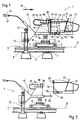
- Fig. 1 and 2 one side view of a machine for track maintenance
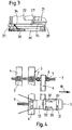
- Fig. 3 an enlarged detail view
- Fig. 4 a top view of the machine.
- An in Fig. 1 illustrated machine 1 is designed for mounting of rail terminals 2, by means of which rails 3 and sleepers 4 of a track 5 are interconnected.
- the machine 1 has a chassis frame 6, which is mounted on the two rails 3 via a respective - equipped with flange wheels 7 - chassis 8 is stored or unrolled.
- One in the track transverse direction extending transverse guide 9 connects the two trolleys 8 with each other and serves for transversely movable mounting of a carriage 10th
- the unit frame 11 is connected at its one, distant from the hinge point 13 end acted upon by actuators 14 working tools 15 and two control elements 17 having handles 16.
- a - with respect to a direction of displacement 18 of the machine 1 - front end 19 of the working unit 12 is connected by a coupling 20 with a motor unit 21.
- the motor unit 21 is composed of a motor 22, a hydraulic pump 23, a hydraulic tank 24, a cooler 25 and an electric generator 26 with an alternator and can be transported by handles 27 (s. Fig. 2 ).
- line couplings 28 for releasably connecting provided for acting on the actuators 14 hydraulic lines 29 and of a motor control line 30 are arranged.
- the coupling 20 provided for connecting motor and working unit 21, 12 is connected by two mutually parallel, connected to the working unit 12 - and approximately parallel to one through the Flange wheels 7 and rails 3 formed driving plane 31 extending coupling pins 32 on the one hand and serving to receive the same, connected to the motor unit 21 coupling sleeves 33 on the other hand, and formed by a locking device 34.
- the motor unit 21 has a first frame 35 connected to the motor 22 and a second frame 36 connected to the coupling sleeves 33.
- the two superposed frames 35, 36 are connected to each other exclusively by damping elements 37.
- the line couplings 28 are formed on the one hand with the motor unit 21 and on the other hand with the working unit 12 connected to the coupling block 38 for a by the sliding of the motor unit 21 on the coupling pins 32 automatically coupling of the hydraulic and motor control lines 29, 30.
- a valve control 39 provided for controlling the working tools 15 is arranged on the working unit 12. Alternatively, a manual clutch could be performed instead of the automatic clutch.
- the chassis frame 6 is first placed on the rails 3. Subsequently, the working unit 12 can be easily carried by detecting the handles 16 on the one hand and the coupling pins 32 on the other hand and fixed on the hinge joint 13. Finally, the motor unit 21 is detected by means of the handles 27, pushed onto the coupling pins 32 and fixed by the locking device 34. With the Aufschiebezi is automatically a clutch of the hydraulic and motor control line 29, 30, whereby the machine 1 is fully assembled and ready for use. The removal of the machine 1 from the track 5 can also be easily performed in three parts by first withdrawing the motor unit 21 from the coupling pins 32. As a result, the working unit 12 is separated from the chassis frame 6 and transported away.
Landscapes
- Engineering & Computer Science (AREA)
- Architecture (AREA)
- Civil Engineering (AREA)
- Structural Engineering (AREA)
- Machines For Laying And Maintaining Railways (AREA)
- Railway Tracks (AREA)
- Handcart (AREA)
Description
- Die Erfindung betrifft eine händisch verschiebbare Maschine für die Gleiserhaltung, bestehend aus einer zwei Handgriffe sowie durch Antriebe beaufschlagbare Arbeitswerkzeuge aufweisenden Arbeitseinheit und einer an diese angeschlossenen, zur Energieversorgung dienenden Motoreinheit, wobei die Arbeits- und Motoreinheit durch einen Aggregatrahmen der Arbeitseinheit mittels Gelenkverbindung mit einem zur Auflage auf Schienen eines Gleises vorgesehenen und Spurkranzrollen aufweisenden Fahrwerksrahmen verbunden ist.
- Eine derartige Maschine ist durch
FR 2 659 674 DE 20305569 U1 bekannt, wobei die Arbeitswerkzeuge zur Montage von Schienenklemmen dienen. Die Maschine wird im Arbeitseinsatz mit Hilfe der Handgriffe auf dem Gleis zur nächstfolgenden Schwelle verschoben. Da derartige Maschinen relativ schwer sind, erreicht deren händische Entfernung aus dem Gleis bzw. die Überstellung auf das Gleis Grenzwerte einer körperlichen Belastung der Bedienungskräfte. - Aus
WO 2006/031168 A1 ist eine einfache Maschine bekannt, die sich aus einer Motor- und einer Arbeitseinheit ohne Aggregat- und Fahrwerksrahmen zusammensetzt. - Die Aufgabe der vorliegenden Erfindung liegt nun in der Schaffung einer Maschine der eingangs genannten Art, mit der eine vereinfachte Überstellung in die Arbeitsposition bzw. Entfernung aus dem Gleis ermöglicht wird.
- Diese Aufgabe wird erfindungsgemäß mit einer Maschine der gattungsgemäßen Art durch die im Kennzeichen des Hauptanspruches angeführten Merkmale gelöst.
- Mit diesen Merkmalen können Motoreinheit und Arbeitseinheit für eine wesentliche körperliche Entlastung der Bedienungspersonen getrennt transportiert und bedarfsweise sehr einfach wieder miteinander verbunden werden. Für den Transport der Arbeitseinheit sind in vorteilhafter Weise abstehende Kupplungsteile als Handgriffe nutzbar. Außerdem kann die Motoreinheit zur vielseitigen Verwendung auch an verschiedene, für unterschiedliche Funktionen ausgebildete Arbeitseinheiten zu deren Energieversorgung angekuppelt werden.
- Weitere Vorteile der Erfindung ergeben sich aus den Unteransprüchen und der Zeichnungsbeschreibung.
- Im Folgenden wird die Erfindung anhand eines in der Zeichnung dargestellten Ausführungsbeispieles näher beschrieben. Es zeigen:
Fig. 1 und 2 je eine Seitenansicht einer Maschine für die Gleiserhaltung,Fig. 3 eine vergrößerte Detailansicht, undFig. 4 eine Draufsicht auf die Maschine. - Eine in
Fig. 1 dargestellte Maschine 1 ist zur Montage von Schienenklemmen 2 ausgebildet, mittels derer Schienen 3 und Schwellen 4 eines Gleises 5 miteinander verbunden werden. Die Maschine 1 weist einen Fahrwerksrahmen 6 auf, der auf den beiden Schienen 3 über je ein - mit Spurkranzrollen 7 ausgestattetes - Fahrwerk 8 gelagert bzw. abrollbar ist. Eine sich in Gleisquerrichtung erstreckende Querführung 9 verbindet die beiden Fahrwerke 8 miteinander und dient zur querverschiebbaren Lagerung eines Schlittens 10. - Auf diesem Schlitten 10 ist ein in Gleis- bzw. Schienenlängsrichtung verlaufender Aggregatrahmen 11 einer Arbeitseinheit 12 gelagert, der mittels einer Gelenkverbindung 13 relativ zum Fahrwerksrahmen 6 dreh- und kippbar ausgebildet und anhand der Querführung 9 wahlweise über der einen oder anderen Schiene 3 des Gleises 5 positionierbar ist (s.
Fig. 4 ). - Der Aggregatrahmen 11 ist an seinem einen, von der Gelenkstelle 13 distanzierten Ende mit durch Antriebe 14 beaufschlagbaren Arbeitswerkzeugen 15 sowie mit zwei Steuerungselemente 17 aufweisenden Handgriffen 16 verbunden. Ein - bezüglich einer Verschieberichtung 18 der Maschine 1 - vorderes Ende 19 der Arbeitseinheit 12 ist durch eine Kupplung 20 mit einer Motoreinheit 21 verbunden.
- Die Motoreinheit 21 setzt sich aus einem Motor 22, einer Hydraulikpumpe 23 , einem Hydrauliktank 24, einem Kühler 25 sowie einem elektrischen Generator 26 mit einer Lichtmaschine zusammen und ist durch Handgriffe 27 transportierbar (s.
Fig. 2 ). Zwischen Motor- und Arbeitseinheit (21, 12) sind Leitungskupplungen 28 zur lösbaren Verbindung von zur Beaufschlagung der Antriebe 14 vorgesehenen Hydraulikleitungen 29 sowie von einer Motorsteuerleitung 30 angeordnet. - Die zur Verbindung von Motor- und Arbeitseinheit 21, 12 vorgesehene Kupplung 20 ist durch zwei parallel zueinander verlaufende, mit der Arbeitseinheit 12 verbundene - und etwa parallel zu einer durch die Spurkranzrollen 7 bzw. Schienen 3 gebildeten Fahrebene 31 verlaufende-Kupplungsstifte 32 einerseits und durch zur Aufnahme derselben dienende, mit der Motoreinheit 21 verbundene Kupplungshülsen 33 andererseits, sowie durch eine Arretiervorrichtung 34 gebildet.
- Wie in
Fig. 3 ersichtlich, weist die Motoreinheit 21 einen mit dem Motor 22 verbundenen ersten Rahmen 35 und einen mit den Kupplungshülsen 33 verbundenen zweiten Rahmen 36 auf. Die beiden übereinander positionierten Rahmen 35, 36 sind ausschließlich durch Dämpfungselemente 37 miteinander verbunden. - Die Leitungskupplungen 28 sind als einerseits mit der Motoreinheit 21 und andererseits mit der Arbeitseinheit 12 verbundener Kupplungsblock 38 für eine durch das Aufschieben der Motoreinheit 21 auf die Kupplungsstifte 32 automatisch erfolgende Kupplung der Hydraulik- und Motorsteuerleitungen 29, 30 ausgebildet. Eine zur Steuerung der Arbeitswerkzeuge 15 vorgesehene Ventilsteuerung 39 ist auf der Arbeitseinheit 12 angeordnet. Alternativ könnte anstelle der automatischen Kupplung auch eine manuelle Kupplung durchgeführt werden.
- Für einen Arbeitseinsatz der Maschine 1 wird zuerst der Fahrwerksrahmen 6 auf die Schienen 3 abgestellt. Anschließend kann die Arbeitseinheit 12 durch Erfassen der Handgriffe 16 einerseits und der Kupplungsstifte 32 andererseits mühelos getragen und auf der Gelenkverbindung 13 fixiert werden. Abschließend wird die Motoreinheit 21 mit Hilfe der Handgriffe 27 erfasst, auf die Kupplungsstifte 32 aufgeschoben und durch die Arretiervorrichtung 34 fixiert. Mit der Aufschiebebewegung erfolgt automatisch eine Kupplung der Hydraulik- und Motorsteuerleitung 29, 30, wodurch die Maschine 1 vollständig zusammengebaut und einsatzbereit ist. Die Entfernung der Maschine 1 vom Gleis 5 kann ebenso einfach in drei Teilen durchgeführt werden, indem zuerst die Motoreinheit 21 von den Kupplungsstiften 32 abgezogen wird. In weiterer Folge wird die Arbeitseinheit 12 vom Fahrwerksrahmen 6 getrennt und abtransportiert.
Claims (5)
- Händisch verschiebbare Maschine (1) für die Gleiserhaltung, bestehend aus einer zwei Handgriffe (16) sowie durch Antriebe (14) beaufschlagbare Arbeitswerkzeuge (15) aufweisenden Arbeitseinheit (12) und einer an diese angeschlossenen, zur Energieversorgung dienenden Motoreinheit (21), wobei die Arbeits- und Motoreinheit (12, 21) durch einen Aggregatrahmen (11) der Arbeitseinheit (12) mittels Gelenkverbindung (13) mit einem zur Auflage auf Schienen (3) eines Gleises (5) vorgesehenen und Spurkranzrollen (7) aufweisenden Fahrwerksrahmen (6) verbunden ist,
gekennzeichnet durch folgende Merkmale:a) die Motoreinheit (21) ist mit Handgriffen (27) ausgestattet und durch eine lösbare Kupplung (20) mit dem Aggregatrahmen (11) der Arbeitseinheit (12) verbunden,b) die Motoreinheit (21) setzt sich aus einem Motor (22), einer Hydraulikpumpe (23), einem Hydrauliktank (24), einem Kühler (25) sowie einem elektrischen Generator (26) zusammen,c) zwischen Motor- und Arbeitseinheit (21, 12) sind Leitungskupplungen (28) zur lösbaren Verbindung von zur Beaufschlagung der Arbeitswerkzeuge (15) vorgesehenen Hydraulikleitungen (29) sowie von einer Motorsteuerleitung (30) angeordnet. - Maschine nach Anspruch 1, dadurch gekennzeichnet, dass die zur Verbindung von Motor- und Arbeitseinheit (21, 12) vorgesehene Kupplung (20) durch zwei parallel zueinander verlaufende, mit dem Aggregatrahmen (11) der Arbeitseinheit (12) verbundene und etwa parallel zu einer durch die Spurkranzrollen (7) gebildeten Fahrebene (31) verlaufende Kupplungsstifte (32) einerseits und durch zur Aufnahme derselben dienende, mit der Motoreinheit (21) verbundene Kupplungshülsen (33) andererseits, sowie durch eine Arretiervorrichtung (34) gebildet ist.
- Maschine nach Anspruch 1 oder 2, dadurch gekennzeichnet, dass die Motoreinheit (21) einen mit dem Motor (22) verbundenen ersten Rahmen (35) und einen mit den Kupplungshülsen (33) verbundenen zweiten Rahmen (36) aufweist, wobei die beiden Rahmen (35, 36) durch Dämpfungselemente (37) miteinander verbunden sind.
- Maschine nach Anspruch 1 oder 2, dadurch gekennzeichnet, dass die Leitungskupplungen (28) als einerseits mit der Motoreinheit (21) und andererseits mit der Arbeitseinheit (12) verbundener Kupplungsblock (38) für eine durch das Aufschieben der Motoreinheit (21) auf die Kupplungsstifte (32) automatische Kupplung der Hydraulik- und Motorsteuerleitung (29, 30) ausgebildet sind.
- Maschine nach Anspruch 1, dadurch gekennzeichnet, dass eine zur Steuerung der Arbeitswerkzeuge (15) vorgesehene Ventilsteuerung (39) auf der Arbeitseinheit (12) angeordnet ist.
Priority Applications (1)
| Application Number | Priority Date | Filing Date | Title |
|---|---|---|---|
| PL13744967T PL2935698T3 (pl) | 2012-08-16 | 2013-07-25 | Przesuwalna ręcznie maszyna do konserwacji torów kolejowych |
Applications Claiming Priority (2)
| Application Number | Priority Date | Filing Date | Title |
|---|---|---|---|
| DE202012007818U DE202012007818U1 (de) | 2012-08-16 | 2012-08-16 | Händisch verschiebbare Maschine für die Gleiserhaltung |
| PCT/EP2013/002212 WO2014026729A1 (de) | 2012-08-16 | 2013-07-25 | Händisch verschiebbare maschine für die gleiserhaltung |
Publications (2)
| Publication Number | Publication Date |
|---|---|
| EP2935698A1 EP2935698A1 (de) | 2015-10-28 |
| EP2935698B1 true EP2935698B1 (de) | 2018-09-12 |
Family
ID=47070842
Family Applications (1)
| Application Number | Title | Priority Date | Filing Date |
|---|---|---|---|
| EP13744967.4A Active EP2935698B1 (de) | 2012-08-16 | 2013-07-25 | Händisch verschiebbare maschine für die gleiserhaltung |
Country Status (11)
| Country | Link |
|---|---|
| US (1) | US9528224B2 (de) |
| EP (1) | EP2935698B1 (de) |
| JP (1) | JP6203260B2 (de) |
| KR (1) | KR102115628B1 (de) |
| CN (1) | CN104520507B (de) |
| AU (1) | AU2013304342B2 (de) |
| CA (1) | CA2878760C (de) |
| DE (1) | DE202012007818U1 (de) |
| DK (1) | DK2935698T3 (de) |
| PL (1) | PL2935698T3 (de) |
| WO (1) | WO2014026729A1 (de) |
Families Citing this family (4)
| Publication number | Priority date | Publication date | Assignee | Title |
|---|---|---|---|---|
| DE202016005841U1 (de) | 2016-09-22 | 2016-11-07 | Robel Bahnbaumaschinen Gmbh | Manuell auf einem Gleis verschiebbare Maschine zur Gleisbearbeitung |
| CN108642980B (zh) * | 2018-05-28 | 2019-12-31 | 中铁十六局集团有限公司 | 运营铁路路基维修快速整体无损移除无砟轨道板施工工法 |
| WO2021231796A1 (en) * | 2020-05-13 | 2021-11-18 | Focused Technology Solutions, Inc. | Railway clip positioning, setting, and insertion system |
| DE102020207441A1 (de) | 2020-06-16 | 2021-12-16 | Robel Bahnbaumaschinen Gmbh | Bearbeitungsmaschine und Verfahren zur Gleisbearbeitung |
Family Cites Families (15)
| Publication number | Priority date | Publication date | Assignee | Title |
|---|---|---|---|---|
| US2607251A (en) * | 1944-05-04 | 1952-08-19 | Nordberg Manufacturing Co | Power transmission for trackworking tools and the like |
| US2552655A (en) * | 1944-05-04 | 1951-05-15 | Nordberg Manufacturing Co | Machine operated track wrench |
| US3120193A (en) * | 1957-11-29 | 1964-02-04 | True Temper Corp | Rail anchor driving machines |
| DE1935427C3 (de) * | 1969-07-11 | 1980-10-16 | Franz Plasser Bahnbaumaschinen- Industriegesellschaft Mbh, Wien | Hydrostatisches Nagelziehgerät |
| GB1509900A (en) * | 1974-09-16 | 1978-05-04 | Pandrol Ltd | Driving of rail clips in assembling a railway rail-and-fastening assembly |
| FR2659674A1 (fr) | 1990-03-19 | 1991-09-20 | Geismar Anc Ets L | Machine pour la mise en place et l'extraction d'organes d'attache notamment des rails aux traverses d'une voie ferree. |
| JP2525121B2 (ja) * | 1992-10-05 | 1996-08-14 | 東日本旅客鉄道株式会社 | クリップ型レ―ル締結具の着脱装置 |
| KR100280607B1 (ko) * | 1998-04-14 | 2001-02-01 | 김대원 | 보선용 클립 체결장치 |
| CN2497933Y (zh) * | 2001-07-31 | 2002-07-03 | 王迅 | 全液压动力扳手 |
| DE20218233U1 (de) * | 2002-11-25 | 2003-02-20 | ROBEL Bahnbaumaschinen GmbH, 83395 Freilassing | Vorrichtung zur Montage von Schienenklemmen |
| DE20304727U1 (de) * | 2003-03-25 | 2003-05-28 | ROBEL Bahnbaumaschinen GmbH, 83395 Freilassing | Vorrichtung zur Montage von Schienenklemmen |
| DE20305569U1 (de) | 2003-04-07 | 2003-06-18 | ROBEL Bahnbaumaschinen GmbH, 83395 Freilassing | Vorrichtung zur Montage von Schienenklemmen |
| DE202004010216U1 (de) * | 2004-06-30 | 2004-09-09 | Robel Bahnbaumaschinen Gmbh | Nagelziehmaschine |
| SE528641C2 (sv) * | 2004-09-17 | 2007-01-09 | Rosenqvist Rail Tech Ab | Ett av en operatör lätt manövrerbart arrangemang |
| SE535365C2 (sv) * | 2010-11-19 | 2012-07-10 | Rosenqvist Rail Ab | Handmanövrerbart arrangemang |
-
2012
- 2012-08-16 DE DE202012007818U patent/DE202012007818U1/de not_active Expired - Lifetime
-
2013
- 2013-07-25 PL PL13744967T patent/PL2935698T3/pl unknown
- 2013-07-25 CA CA2878760A patent/CA2878760C/en not_active Expired - Fee Related
- 2013-07-25 DK DK13744967.4T patent/DK2935698T3/en active
- 2013-07-25 WO PCT/EP2013/002212 patent/WO2014026729A1/de not_active Ceased
- 2013-07-25 KR KR1020157001390A patent/KR102115628B1/ko active Active
- 2013-07-25 AU AU2013304342A patent/AU2013304342B2/en active Active
- 2013-07-25 JP JP2015526892A patent/JP6203260B2/ja active Active
- 2013-07-25 CN CN201380041289.5A patent/CN104520507B/zh active Active
- 2013-07-25 EP EP13744967.4A patent/EP2935698B1/de active Active
- 2013-07-25 US US14/420,033 patent/US9528224B2/en active Active
Non-Patent Citations (1)
| Title |
|---|
| None * |
Also Published As
| Publication number | Publication date |
|---|---|
| CA2878760C (en) | 2019-10-22 |
| WO2014026729A1 (de) | 2014-02-20 |
| AU2013304342A1 (en) | 2015-02-19 |
| DK2935698T3 (en) | 2019-01-14 |
| US9528224B2 (en) | 2016-12-27 |
| JP2015529761A (ja) | 2015-10-08 |
| US20150225904A1 (en) | 2015-08-13 |
| CA2878760A1 (en) | 2014-02-20 |
| KR102115628B1 (ko) | 2020-05-26 |
| KR20150043293A (ko) | 2015-04-22 |
| EP2935698A1 (de) | 2015-10-28 |
| JP6203260B2 (ja) | 2017-09-27 |
| CN104520507A (zh) | 2015-04-15 |
| PL2935698T3 (pl) | 2019-04-30 |
| DE202012007818U1 (de) | 2012-09-24 |
| HK1205539A1 (en) | 2015-12-18 |
| CN104520507B (zh) | 2017-03-08 |
| AU2013304342B2 (en) | 2017-08-17 |
Similar Documents
| Publication | Publication Date | Title |
|---|---|---|
| EP2167268B1 (de) | Strangbrennschneidmaschine mit einem ortfest drehbaren kranturm | |
| DE102009040200B4 (de) | Transportvorrichtung für ein längliches Objekt | |
| DE3835758C2 (de) | Kombinierte Schienenverschiebe- und -schweißvorrichtung | |
| EP2935698B1 (de) | Händisch verschiebbare maschine für die gleiserhaltung | |
| EP3455152B1 (de) | Schienenkran zum transport von schienen | |
| EP3408154A1 (de) | Instandhaltungsfahrzeug | |
| AT506585B1 (de) | Stopfmaschine | |
| DE3430002C2 (de) | ||
| AT508755B1 (de) | Stopfmaschine mit einer zusatzhebeeinrichtung | |
| EP2756132A1 (de) | Maschine zur entfernung von schotter eines gleises | |
| EP1736602A1 (de) | Schweissmaschine zum Verschweissen von Schienen eines Gleises | |
| EP3201395B1 (de) | Schweissaggregat | |
| CH704459B1 (de) | Verfahren zur Inbetriebnahme einer Räumvorrichtung sowie eine Gleisbaumaschine mit einer solchen Räumvorrichtung. | |
| DE102004018385A1 (de) | Vorrichtung zum Setzen von Bauteilen, wie Pfosten,Pfählen oder dergleichen | |
| EP2622140B1 (de) | Stopfmaschine | |
| WO2010112107A1 (de) | Maschine zur erneuerung eines gleises | |
| EP3411527B1 (de) | Schweissaggregat zum verschweissen von schienen eines gleises | |
| EP2155967B1 (de) | Portalkran | |
| EP3082978B1 (de) | Absturzsicherung für eine gleisbaumaschine | |
| DD283439A5 (de) | Fahrbare maschine zum elektrischen abbrennstumpf-verschweissen der beiden aneinanderstossenden enden eines verlegten gleises | |
| EP0985766B1 (de) | Maschine zur Gleisbearbeitung | |
| EP1597436B1 (de) | Maschine und verfahren zur bearbeitung eines gleises | |
| WO2020043431A1 (de) | Bearbeitungsmaschine und verfahren zur bearbeitung eines gleises | |
| EP3480359A1 (de) | Gleisbauvorrichtung zur bearbeitung von schienen | |
| EP3469141B1 (de) | Fahrzeug und verfahren zum transport einer mobilen schweissvorrichtung |
Legal Events
| Date | Code | Title | Description |
|---|---|---|---|
| PUAI | Public reference made under article 153(3) epc to a published international application that has entered the european phase |
Free format text: ORIGINAL CODE: 0009012 |
|
| 17P | Request for examination filed |
Effective date: 20150226 |
|
| AK | Designated contracting states |
Kind code of ref document: A1 Designated state(s): AL AT BE BG CH CY CZ DE DK EE ES FI FR GB GR HR HU IE IS IT LI LT LU LV MC MK MT NL NO PL PT RO RS SE SI SK SM TR |
|
| AX | Request for extension of the european patent |
Extension state: BA ME |
|
| DAX | Request for extension of the european patent (deleted) | ||
| STAA | Information on the status of an ep patent application or granted ep patent |
Free format text: STATUS: EXAMINATION IS IN PROGRESS |
|
| 17Q | First examination report despatched |
Effective date: 20170323 |
|
| GRAP | Despatch of communication of intention to grant a patent |
Free format text: ORIGINAL CODE: EPIDOSNIGR1 |
|
| STAA | Information on the status of an ep patent application or granted ep patent |
Free format text: STATUS: GRANT OF PATENT IS INTENDED |
|
| INTG | Intention to grant announced |
Effective date: 20180322 |
|
| GRAS | Grant fee paid |
Free format text: ORIGINAL CODE: EPIDOSNIGR3 |
|
| GRAA | (expected) grant |
Free format text: ORIGINAL CODE: 0009210 |
|
| STAA | Information on the status of an ep patent application or granted ep patent |
Free format text: STATUS: THE PATENT HAS BEEN GRANTED |
|
| AK | Designated contracting states |
Kind code of ref document: B1 Designated state(s): AL AT BE BG CH CY CZ DE DK EE ES FI FR GB GR HR HU IE IS IT LI LT LU LV MC MK MT NL NO PL PT RO RS SE SI SK SM TR |
|
| REG | Reference to a national code |
Ref country code: GB Ref legal event code: FG4D Free format text: NOT ENGLISH |
|
| REG | Reference to a national code |
Ref country code: CH Ref legal event code: EP |
|
| REG | Reference to a national code |
Ref country code: IE Ref legal event code: FG4D Free format text: LANGUAGE OF EP DOCUMENT: GERMAN |
|
| REG | Reference to a national code |
Ref country code: DE Ref legal event code: R096 Ref document number: 502013011075 Country of ref document: DE |
|
| REG | Reference to a national code |
Ref country code: AT Ref legal event code: REF Ref document number: 1040730 Country of ref document: AT Kind code of ref document: T Effective date: 20181015 |
|
| REG | Reference to a national code |
Ref country code: SE Ref legal event code: TRGR Ref country code: NL Ref legal event code: FP |
|
| REG | Reference to a national code |
Ref country code: DK Ref legal event code: T3 Effective date: 20190106 |
|
| REG | Reference to a national code |
Ref country code: LT Ref legal event code: MG4D |
|
| PG25 | Lapsed in a contracting state [announced via postgrant information from national office to epo] |
Ref country code: BG Free format text: LAPSE BECAUSE OF FAILURE TO SUBMIT A TRANSLATION OF THE DESCRIPTION OR TO PAY THE FEE WITHIN THE PRESCRIBED TIME-LIMIT Effective date: 20181212 Ref country code: LT Free format text: LAPSE BECAUSE OF FAILURE TO SUBMIT A TRANSLATION OF THE DESCRIPTION OR TO PAY THE FEE WITHIN THE PRESCRIBED TIME-LIMIT Effective date: 20180912 Ref country code: RS Free format text: LAPSE BECAUSE OF FAILURE TO SUBMIT A TRANSLATION OF THE DESCRIPTION OR TO PAY THE FEE WITHIN THE PRESCRIBED TIME-LIMIT Effective date: 20180912 Ref country code: GR Free format text: LAPSE BECAUSE OF FAILURE TO SUBMIT A TRANSLATION OF THE DESCRIPTION OR TO PAY THE FEE WITHIN THE PRESCRIBED TIME-LIMIT Effective date: 20181213 Ref country code: FI Free format text: LAPSE BECAUSE OF FAILURE TO SUBMIT A TRANSLATION OF THE DESCRIPTION OR TO PAY THE FEE WITHIN THE PRESCRIBED TIME-LIMIT Effective date: 20180912 |
|
| REG | Reference to a national code |
Ref country code: NO Ref legal event code: T2 Effective date: 20180912 |
|
| PG25 | Lapsed in a contracting state [announced via postgrant information from national office to epo] |
Ref country code: AL Free format text: LAPSE BECAUSE OF FAILURE TO SUBMIT A TRANSLATION OF THE DESCRIPTION OR TO PAY THE FEE WITHIN THE PRESCRIBED TIME-LIMIT Effective date: 20180912 Ref country code: HR Free format text: LAPSE BECAUSE OF FAILURE TO SUBMIT A TRANSLATION OF THE DESCRIPTION OR TO PAY THE FEE WITHIN THE PRESCRIBED TIME-LIMIT Effective date: 20180912 Ref country code: LV Free format text: LAPSE BECAUSE OF FAILURE TO SUBMIT A TRANSLATION OF THE DESCRIPTION OR TO PAY THE FEE WITHIN THE PRESCRIBED TIME-LIMIT Effective date: 20180912 |
|
| PG25 | Lapsed in a contracting state [announced via postgrant information from national office to epo] |
Ref country code: EE Free format text: LAPSE BECAUSE OF FAILURE TO SUBMIT A TRANSLATION OF THE DESCRIPTION OR TO PAY THE FEE WITHIN THE PRESCRIBED TIME-LIMIT Effective date: 20180912 Ref country code: IT Free format text: LAPSE BECAUSE OF FAILURE TO SUBMIT A TRANSLATION OF THE DESCRIPTION OR TO PAY THE FEE WITHIN THE PRESCRIBED TIME-LIMIT Effective date: 20180912 Ref country code: IS Free format text: LAPSE BECAUSE OF FAILURE TO SUBMIT A TRANSLATION OF THE DESCRIPTION OR TO PAY THE FEE WITHIN THE PRESCRIBED TIME-LIMIT Effective date: 20190112 Ref country code: RO Free format text: LAPSE BECAUSE OF FAILURE TO SUBMIT A TRANSLATION OF THE DESCRIPTION OR TO PAY THE FEE WITHIN THE PRESCRIBED TIME-LIMIT Effective date: 20180912 Ref country code: ES Free format text: LAPSE BECAUSE OF FAILURE TO SUBMIT A TRANSLATION OF THE DESCRIPTION OR TO PAY THE FEE WITHIN THE PRESCRIBED TIME-LIMIT Effective date: 20180912 |
|
| PG25 | Lapsed in a contracting state [announced via postgrant information from national office to epo] |
Ref country code: SK Free format text: LAPSE BECAUSE OF FAILURE TO SUBMIT A TRANSLATION OF THE DESCRIPTION OR TO PAY THE FEE WITHIN THE PRESCRIBED TIME-LIMIT Effective date: 20180912 Ref country code: PT Free format text: LAPSE BECAUSE OF FAILURE TO SUBMIT A TRANSLATION OF THE DESCRIPTION OR TO PAY THE FEE WITHIN THE PRESCRIBED TIME-LIMIT Effective date: 20190112 Ref country code: SM Free format text: LAPSE BECAUSE OF FAILURE TO SUBMIT A TRANSLATION OF THE DESCRIPTION OR TO PAY THE FEE WITHIN THE PRESCRIBED TIME-LIMIT Effective date: 20180912 |
|
| REG | Reference to a national code |
Ref country code: DE Ref legal event code: R097 Ref document number: 502013011075 Country of ref document: DE |
|
| PLBE | No opposition filed within time limit |
Free format text: ORIGINAL CODE: 0009261 |
|
| STAA | Information on the status of an ep patent application or granted ep patent |
Free format text: STATUS: NO OPPOSITION FILED WITHIN TIME LIMIT |
|
| 26N | No opposition filed |
Effective date: 20190613 |
|
| PG25 | Lapsed in a contracting state [announced via postgrant information from national office to epo] |
Ref country code: SI Free format text: LAPSE BECAUSE OF FAILURE TO SUBMIT A TRANSLATION OF THE DESCRIPTION OR TO PAY THE FEE WITHIN THE PRESCRIBED TIME-LIMIT Effective date: 20180912 |
|
| PG25 | Lapsed in a contracting state [announced via postgrant information from national office to epo] |
Ref country code: MC Free format text: LAPSE BECAUSE OF FAILURE TO SUBMIT A TRANSLATION OF THE DESCRIPTION OR TO PAY THE FEE WITHIN THE PRESCRIBED TIME-LIMIT Effective date: 20180912 |
|
| PG25 | Lapsed in a contracting state [announced via postgrant information from national office to epo] |
Ref country code: LU Free format text: LAPSE BECAUSE OF NON-PAYMENT OF DUE FEES Effective date: 20190725 |
|
| PG25 | Lapsed in a contracting state [announced via postgrant information from national office to epo] |
Ref country code: IE Free format text: LAPSE BECAUSE OF NON-PAYMENT OF DUE FEES Effective date: 20190725 |
|
| PGFP | Annual fee paid to national office [announced via postgrant information from national office to epo] |
Ref country code: NL Payment date: 20200729 Year of fee payment: 8 |
|
| PGFP | Annual fee paid to national office [announced via postgrant information from national office to epo] |
Ref country code: CZ Payment date: 20200722 Year of fee payment: 8 Ref country code: TR Payment date: 20200723 Year of fee payment: 8 Ref country code: NO Payment date: 20200630 Year of fee payment: 8 Ref country code: DK Payment date: 20200722 Year of fee payment: 8 |
|
| PGFP | Annual fee paid to national office [announced via postgrant information from national office to epo] |
Ref country code: SE Payment date: 20200724 Year of fee payment: 8 Ref country code: BE Payment date: 20200722 Year of fee payment: 8 Ref country code: PL Payment date: 20200715 Year of fee payment: 8 Ref country code: CH Payment date: 20200724 Year of fee payment: 8 |
|
| PG25 | Lapsed in a contracting state [announced via postgrant information from national office to epo] |
Ref country code: CY Free format text: LAPSE BECAUSE OF FAILURE TO SUBMIT A TRANSLATION OF THE DESCRIPTION OR TO PAY THE FEE WITHIN THE PRESCRIBED TIME-LIMIT Effective date: 20180912 |
|
| PG25 | Lapsed in a contracting state [announced via postgrant information from national office to epo] |
Ref country code: MT Free format text: LAPSE BECAUSE OF FAILURE TO SUBMIT A TRANSLATION OF THE DESCRIPTION OR TO PAY THE FEE WITHIN THE PRESCRIBED TIME-LIMIT Effective date: 20180912 Ref country code: HU Free format text: LAPSE BECAUSE OF FAILURE TO SUBMIT A TRANSLATION OF THE DESCRIPTION OR TO PAY THE FEE WITHIN THE PRESCRIBED TIME-LIMIT; INVALID AB INITIO Effective date: 20130725 |
|
| REG | Reference to a national code |
Ref country code: DK Ref legal event code: EBP Effective date: 20210731 |
|
| REG | Reference to a national code |
Ref country code: CH Ref legal event code: PL Ref country code: NO Ref legal event code: MMEP |
|
| REG | Reference to a national code |
Ref country code: NL Ref legal event code: MM Effective date: 20210801 |
|
| REG | Reference to a national code |
Ref country code: BE Ref legal event code: MM Effective date: 20210731 |
|
| PG25 | Lapsed in a contracting state [announced via postgrant information from national office to epo] |
Ref country code: LI Free format text: LAPSE BECAUSE OF NON-PAYMENT OF DUE FEES Effective date: 20210731 Ref country code: CH Free format text: LAPSE BECAUSE OF NON-PAYMENT OF DUE FEES Effective date: 20210731 |
|
| PG25 | Lapsed in a contracting state [announced via postgrant information from national office to epo] |
Ref country code: SE Free format text: LAPSE BECAUSE OF NON-PAYMENT OF DUE FEES Effective date: 20210726 Ref country code: NO Free format text: LAPSE BECAUSE OF NON-PAYMENT OF DUE FEES Effective date: 20210731 Ref country code: NL Free format text: LAPSE BECAUSE OF NON-PAYMENT OF DUE FEES Effective date: 20210801 Ref country code: CZ Free format text: LAPSE BECAUSE OF NON-PAYMENT OF DUE FEES Effective date: 20210725 |
|
| PG25 | Lapsed in a contracting state [announced via postgrant information from national office to epo] |
Ref country code: MK Free format text: LAPSE BECAUSE OF FAILURE TO SUBMIT A TRANSLATION OF THE DESCRIPTION OR TO PAY THE FEE WITHIN THE PRESCRIBED TIME-LIMIT Effective date: 20180912 |
|
| PG25 | Lapsed in a contracting state [announced via postgrant information from national office to epo] |
Ref country code: DK Free format text: LAPSE BECAUSE OF NON-PAYMENT OF DUE FEES Effective date: 20210731 Ref country code: BE Free format text: LAPSE BECAUSE OF NON-PAYMENT OF DUE FEES Effective date: 20210731 |
|
| PG25 | Lapsed in a contracting state [announced via postgrant information from national office to epo] |
Ref country code: PL Free format text: LAPSE BECAUSE OF NON-PAYMENT OF DUE FEES Effective date: 20210725 |
|
| P01 | Opt-out of the competence of the unified patent court (upc) registered |
Effective date: 20230505 |
|
| PGFP | Annual fee paid to national office [announced via postgrant information from national office to epo] |
Ref country code: AT Payment date: 20230626 Year of fee payment: 11 |
|
| PGFP | Annual fee paid to national office [announced via postgrant information from national office to epo] |
Ref country code: DE Payment date: 20230922 Year of fee payment: 11 |
|
| REG | Reference to a national code |
Ref country code: DE Ref legal event code: R119 Ref document number: 502013011075 Country of ref document: DE |
|
| REG | Reference to a national code |
Ref country code: AT Ref legal event code: MM01 Ref document number: 1040730 Country of ref document: AT Kind code of ref document: T Effective date: 20240725 |
|
| PG25 | Lapsed in a contracting state [announced via postgrant information from national office to epo] |
Ref country code: DE Free format text: LAPSE BECAUSE OF NON-PAYMENT OF DUE FEES Effective date: 20250201 |
|
| PG25 | Lapsed in a contracting state [announced via postgrant information from national office to epo] |
Ref country code: AT Free format text: LAPSE BECAUSE OF NON-PAYMENT OF DUE FEES Effective date: 20240725 |
|
| PGFP | Annual fee paid to national office [announced via postgrant information from national office to epo] |
Ref country code: GB Payment date: 20250724 Year of fee payment: 13 |
|
| PGFP | Annual fee paid to national office [announced via postgrant information from national office to epo] |
Ref country code: FR Payment date: 20250723 Year of fee payment: 13 |