EP2933744B1 - Simulationsverfahren für hochpolymermaterial - Google Patents
Simulationsverfahren für hochpolymermaterial Download PDFInfo
- Publication number
- EP2933744B1 EP2933744B1 EP15163451.6A EP15163451A EP2933744B1 EP 2933744 B1 EP2933744 B1 EP 2933744B1 EP 15163451 A EP15163451 A EP 15163451A EP 2933744 B1 EP2933744 B1 EP 2933744B1
- Authority
- EP
- European Patent Office
- Prior art keywords
- bonding
- target
- particle
- particles
- models
- Prior art date
- Legal status (The legal status is an assumption and is not a legal conclusion. Google has not performed a legal analysis and makes no representation as to the accuracy of the status listed.)
- Active
Links
Images













Classifications
-
- G—PHYSICS
- G16—INFORMATION AND COMMUNICATION TECHNOLOGY [ICT] SPECIALLY ADAPTED FOR SPECIFIC APPLICATION FIELDS
- G16C—COMPUTATIONAL CHEMISTRY; CHEMOINFORMATICS; COMPUTATIONAL MATERIALS SCIENCE
- G16C20/00—Chemoinformatics, i.e. ICT specially adapted for the handling of physicochemical or structural data of chemical particles, elements, compounds or mixtures
- G16C20/30—Prediction of properties of chemical compounds, compositions or mixtures
-
- G—PHYSICS
- G06—COMPUTING OR CALCULATING; COUNTING
- G06F—ELECTRIC DIGITAL DATA PROCESSING
- G06F30/00—Computer-aided design [CAD]
- G06F30/20—Design optimisation, verification or simulation
-
- G—PHYSICS
- G06—COMPUTING OR CALCULATING; COUNTING
- G06F—ELECTRIC DIGITAL DATA PROCESSING
- G06F30/00—Computer-aided design [CAD]
- G06F30/20—Design optimisation, verification or simulation
- G06F30/25—Design optimisation, verification or simulation using particle-based methods
Definitions
- the present invention relates to a simulation method for a high-polymer material which is useful for estimating and improving the dispersion of filler.
- a high-polymer material e.g. rubber
- filler e.g. carbon black, silica and the like
- a numerical model of the filler is defined by a plurality of particles (hereinafter "F-particle")
- a numerical model of the high-polymer material is defined by a plurality of particles (hereinafter "P-particle”). Then, the P-particles are bound with the F-particles, and a molecular dynamics calculation is performed by a computer.
- EP 2 672 405 A1 discloses a method for simulating the dispersion of fillers comprising a filler model defining step, a polymer model defining step and executing a molecular dynamics calculation by using the filler models and the polymer models.
- a primary object of the present invention to provide a simulation method for a high-polymer material in which, a calculation failure during a molecular dynamics calculation is efficiency prevented by limiting the number of P-particles to be bound with each F-particle not to exceed a predetermined upper limit value.
- a simulation method for a high-polymer material is a computer-implemented method for estimating the dispersion of filler contained in the high-polymer material, and comprises:
- F-particle means a particle of a filler model.
- P-particle means a particle of a polymer model.
- the bonding process may include:
- the selecting process may include:
- the F-particles of each filler model include those disposed at apexes of a polyhedron, and the bonding-target F-particles are the F-particles disposed at the apexes.
- a simulation method for a high-polymer material is a computer-implemented method for estimating the dispersion of filler contained in the high-polymer material together with a coupling agent for coupling the filler with polymer by the use of a computer, comprises:
- F-particle means a particle of a filler model.
- P-particle means a particle of a polymer model.
- C-particle means a particle of a coupling agent model.
- Ns Na + Nc / Nb + 1
- the bonding process may include:
- the selecting process may include:
- the F-particles of each filler model include those disposed at apexes of a polyhedron, and the bonding-target F-particles are the F-particles disposed at the apexes.
- the number of bonding-target P-particle(s) and/or C-particle(s) to be bound with each bonding-target F-particle does not exceed the predetermined upper limit value to prevent an excessive increase in the summation of forces of the bonding-target P-particle(s) and/or C-particle(s) exerted on each bonding-target F-particle, therefore, it is possible to perform the molecular dynamics calculation stably without causing calculation failure.
- the simulation method for a high-polymer material according the present invention is a computer-implemented method for estimating the dispersion of filler contained in the high-polymer material.
- the filler may be carbon black, silica, alumina or the like.
- the high-polymer material may be rubber, resin, elastomer or the like.
- the computer 1 for implementing the simulation method according to the present invention comprises a main body 1a, a keyboard 1b, a mouse 1c and a display 1d.
- the main body 1a comprises an arithmetic processing unit (CPU), memories storage devices such as magnetic disk, disk drives 1a1 and 1a2 and the like. In the storage device, programs/software for carrying out the simulating method are stored.
- CPU arithmetic processing unit
- memories storage devices such as magnetic disk, disk drives 1a1 and 1a2 and the like.
- programs/software for carrying out the simulating method are stored.
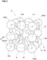
- Each filler model 3 is a particle model made up of F-particles 4 as shown in Fig. 3 .
- F-particle means a particle of a filler model 3.
- the F-particles 4 are arranged to accord with a predetermined polyhedron 13.
- the polyhedron 13 is a regular hexahedron.
- the surface F-particles 4s in this example are identical to The surface F-particles 4s in this example.
- the center F-particle 4c and the surface F-particles 4s are each defined as a sphere having a certain diameter.
- the filler models 3 are numerical data processable with the computer 1 and stored in the computer 1.
- Such numerical data may include the mass, volume and diameter of each F-particle 4, and initial coordinate values of the F-particles 4.
- the equilibrium lengths are equal to the bond distances between the center F-particle 4c and each surface F-particles 4s and between the surface F-particles 4s and 4s, at which the relative positions of the surface F-particles 4s on the polyhedron 13 are stably maintained.
- the high-polymer material is numerically modeled by polymer models 5.
- each polymer model 5 is a particle model made up of P-particles 6.
- P-particle means a particle of a polymer model 5.
- the P-particles 6 are each defined as a sphere having a certain diameter.
- the P-particles 6 include a native P-particle 6a and a denatured P-particle 6b for which different potentials are defined.
- links 6j having respective equilibrium lengths are defined so that the polymer model 5 has a three-dimensional straight-chain structure.
- the polymer model 5 is numerical data processable with the computer 1 and stored in the computer 1.
- the numerical data may include the mass, volume, and diameter of each P-particle 6, and initial coordinate values of the P-particles 6.
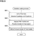
- Fig. 5 shows a flow chart of the condition setting process S3.
- the potential U is a function of the interparticle distance between the concerned two particles and used to calculate a force exerted between the concerned two particles.
- the potential U exerts an interaction force (in this embodiment, a repulsive force).
- the potential U is defined as zero, and does not exert a force (repulsive force) between the two particles.
- the following potentials U1-U10 are defined between different models (3 or 5) and (3 or 5).
- the values of the coefficient a ij (for example, 25) for the potential U2 between the denatured P-particle 6b and the center F-particle 4c, and the potential U5 between the denatured P-particle 6b and the surface F-particles 4s are set to be less than the values of the coefficient a ij (for example 72) for the potential U1 between the native P-particle 6a and the center F-particle 4c, and the potential U4 between the native P-particle 6a and the surface F-particles 4s.
- the values of the coefficient a ij for the potentials U1-U10 are set as follows.
- the denatured P-particle 6b is defined as having a higher affinity for the F-particle (4c, 4s) than the native P-particle 6a. Therefore, the denatured P-particle 6b can model a denatured agent added in the actual high-polymer material. Accordingly, similarly to denaturalizing of the polymer in the actual high-polymer material, by incorporating the denatured P-particle 6b in the polymer model 5, it is possible to change the dispersion of the filler models 3 in the polymer models 5. Thus, the flexibility of the simulation method is increased.
- the cutoff distances r c for the potentials U1-U10 are set as follows.
- Fig. 7 is a diagram for explaining the cutoff distance for the F-particle.
- Each of the cutoff distances r c for the potentials (for example, potential U1) relating to the center F-particle 4c of a filler model 3 is set to be larger than the cutoff distances r c for the potentials (for example, potential U4) relating to the surface F-particles 4s of the filler model 3.
- each of the cutoff distances r c for the potentials (for example, U1) relating to the center F-particle 4c is set to be larger than the sum (r c + L c ) of each of the cutoff distances r c for the potentials (for example, U4) relating to each surface F-particle 4s and the interparticle distance Lc between the above-mentioned surface F-particle 4s and the center F-particle 4c.
- the potentials for example, U1-U3 and U7 relating to the center F-particle 4c can exert interaction forces prior to the potentials (for example, U4, U5 and U8) relating to the surface F-particles 4s.
- the center F-particle 4c is defined as a sphere having a certain diameter
- the potentials (U1-U3 and U7) exert radially or in all directions from the center F-particle 4c. Therefore, in a molecular dynamics calculation performed by the computer 1, a filler model 3 is treated as being a sphere approximate to an actual shape of a filler particle, and as a result, the simulation accuracy is improved.
- the computer 1 can perform the molecular dynamics calculation for the filler models 3 by the use of substantively only the potentials (for example, U1-U3 and U7) relating to the center F-particle 4c of each filler model 3, excluding particles entered into the cutoff distances r c of the surface F-particles 4s thereof.
- substantively only the potentials for example, U1-U3 and U7 relating to the center F-particle 4c of each filler model 3, excluding particles entered into the cutoff distances r c of the surface F-particles 4s thereof.
- the virtual space 9 corresponds to a minute fraction having a microstructure of the rubber polymer as the analysis object.
- the virtual space 9 is defined as being a regular hexahedron whose each side has a length L1 of 30[ ⁇ ] for example.
- 100 filler models 3 and 2000 polymer models 5 are randomly disposed in the virtual space 9.
- the compact cluster of at least two filler models 3 is formed by placing the filler models 3 so that the above-mentioned interaction force between the particles occurs between adjacent filler models 3, in other words, the interparticle distance becomes less than the cutoff distance r c ,
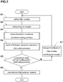
- Fig. 9 shows a flow chart of the simulation process S4 in the first embodiment.
- the Newton's equation of motion is applied to all of the polymer models 5 excluding the immovable filler models 3 on the assumption that they accord with the classical dynamics for a specified period of time in the virtual space 9.
- the P-particles 6a and 6b are traced to obtain their coordinates at each clock time.
- the number of steps of the molecular dynamics calculation is preferably not less than 100, more preferably not less than 1000 but preferably not more than 1000000 if the time interval of one step is 0.05[ ⁇ ] ([ ⁇ ] is a unit of time). If less than 100 steps, it becomes difficult to sufficiently distribute the polymer models 5.
- the polymer models 5 are sufficiently or uniformly distributed through the simulation process S4.
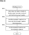
- Fig. 10 is a flow chart of the bonding process S46.
- bonding-target F-particles 15 are selected from the F-particles 4
- bonding-target P-particles 16 are selected from the P-particles 6.
- the bonding-target F-particles 15 are bound with the bonding-target P-particles 16 via links to simulate chemical bond.
- the bonding-target F-particles 15 of each filler model 3 are eight F-particles 4 which are the apex F-particles 7 positioned at the apexes 13a of the polyhedron 13 as shown in Fig. 3 .
- the bonding-target P-particle 16 of each polymer model 5 is, as shown in Fig. 4 , one positioned at the almost center in the length of the straight chain arrangement of the P-particles 6.
- an upper limit value Su for the number Sa of the bonding-target P-particles 16 to be bound with each bonding-target F-particle 15 is defined.
- the upper limit value Su is determined based on the total number Nb of the bonding-target F-particles 15 existing in the virtual space 9 and the total number Na of the bonding-target P-particles 16 existing in the virtual space 9.
- each polymer model 5 has one bonding-target P-particle 16, therefore, the total number Na is equal to the total number (for example, 2000) of the polymer models 5 existing in the virtual space 9.
- Each filler model 3 has eight bonding-target F-particles 15, therefore, the total number Nb is equal to the total number (for example 100) of the filler models 3 existing in the virtual space 9 multiplied by eight.
- the Na/Nb means the number Sa when the bonding-target P-particles 16 are evenly bound with the bonding-target F-particles 15.
- the upper limit value Su for each bonding-target F-particle 15 is defined as 2 or 3.
- Fig. 11 is a flow chart of the selecting process S12.
- each bonding-target P-particle 16 is associated with a bonding-target F-particle 15 to which interparticle distance Lp therefrom is smallest.
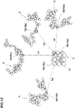
- Fig. 12 is a diagram for explaining this process S21.
- the searched-out bonding-target F-particle 15 is associated with the concerned bonding-target P-particle 16.
- the interparticle distance Lp is the distance between centers of the concerned particles 15 and 16.
- two bonding-target F-particles 15 are shown, which are a first bonding-target F-particle 15a and a second bonding-target F-particle 15b.
- three bonding-target P-particles 16 are associated therewith, which are a first bonding-target P-particle 16a, a second bonding-target P-particle 16b and a third bonding-target P-particle 16c in ascending order of the interparticle distance Lp from the concerned bonding-target F-particle 15.
- a single bonding-target P-particle 16 is associated therewith, which is a fourth bonding-target P-particle 16d.
- each chain double-dashed line indicates an association of a bonding-target F-particle 15 with a bonding-target P-particle 16.
- the selection of the bonding-target P-particle(s) 16 is made in the ascending order of the interparticle distance Lp from the concerned bonding-target F-particle 15 so that the number of the selected bonding-target P-particle(s) 16 does not exceed the above-mentioned upper limit value Su for the number Sa.
- Fig. 13 is a diagram for explaining a process for selecting the bonding-target P-particle(s) 16, where the upper limit value Su is 2.
- a number (which is, in this example, equal to the upper limit value Su) of the bonding-target P-particles (16a and 16b) are selected in their ascending order of the interparticle distance Lp.
- the selected bonding-target P-particles (16a and 16b) are defined as particles to be bound with the first bonding-target F-particle 15a as shown in Fig. 13 , wherein the selected association of a bonding-target F-particle 15 with a bonding-target P-particle 16 is indicate by a solid line instead of the above-mentioned chain double-dashed line.
- each bonding-target P-particle not selected from the group is defined as a particle not to be bound with the first bonding-target F-particle 15a.
- the bonding-target P-particles 16 are selected so that the number Sa of the bonding-target P-particle(s) 16 to be bound with each bonding-target F-particle 15 does not exceed the upper limit value Su.
- identification numbers of each bonding-target F-particle 15 and the bonding-target P-particle(s) 16 selected therefor and their coordinate values in relation to the virtual space 9, are stored in the computer 1.
- each bonding-target P-particle 16 not selected in the 2nd process S22 is associated with another bonding-target F-particle 15. (Third process S23)
- Fig. 14 is a diagram for explaining this process S23.
- the third bonding-target P-particle 16c is a bonding-target P-particle 16 not selected in the 2nd process S22.
- the second bonding-target F-particle 15b is searched out.
- the second bonding-target F-particle 15b is associated with the third bonding-target P-particle 16c.
- bonding-target P-particles 16 to be bound therewith are selected from a group of the bonding-target P-particle(s) associated with the concerned bonding-target F-particle 15 in the third process S23. (Fourth process S24)
- the selection of the bonding-target P-particle(s) 16 is made in the ascending order of the interparticle distance Lp so that the number of the selected bonding-target P-particle(s) 16 satisfies the above-mentioned upper limit value Su for the number Sa.
- Fig. 15 is a diagram for explaining the process S24.
- the single bonding-target P-particle 16 (fourth bonding-target P-particle 16d) has been already selected as explained above.
- the third bonding-target P-particle 16c is associated with the second bonding-target F-particle 15b.
- the third bonding-target P-particle 16c is defined as a particle to be bound with the second bonding-target F-particle 15b.
- the selection from the group of the more than two bonding-target P-particles 16 is made in the ascending order of the interparticle distance Lp so that the resultant number Sa does not exceed the upper limit value Su.
- each bonding-target P-particle 16 (not shown) to which interparticle distance Lp is more than the second smallest, is defined as a particle not bound with the second bonding-target F-particle 15b.
- the bonding-target P-particle(s) 16 to be bound with each bonding-target F-particle 15 is(are) selected from a group of the bonding-target P-particle(s) 16 associated therewith through the third process S23 so that the resultant number Sa does not exceed the upper limit value Su.
- the bonding-target P-particles 16 selected through the selecting process S12 are bound with the bonding-target F-particles 15 via links 10 in order that the filler models 3 and the polymer models 5 can simulate chemical bond between the filler and the polymer.
- Fig. 16 is a diagram for explaining this process S13.
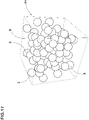
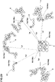
- Fig. 17 is a conceptual perspective view of a simulation model after the molecular dynamics calculation, wherein the polymer models 5 are omitted.
- the F-particles 4c and 4s of each filler model 4 ( Fig. 3 ) and the P-particles 6a and 6b of each polymer model 5 ( Fig. 4 ) are traced to obtain their coordinates at each clock time.
- the conditions such as the number of each of the F-particles 4c and 4s and P-particles 6a and 6b and the volume and temperature of the virtual space 9, are kept unchanged.
- the number Sa of the bonding-target P-particle(s) 16 to be bound with each bonding-target F-particle 15 is limited to a value not more than the predetermined upper limit value Su, so that the summation of the forces of the bonding-target P-particles 16 exerted on each bonding-target F-particle 15 does not increase excessively during the molecular dynamics calculation, therefore, a stable molecular dynamics calculation without failure is possible.
- the upper limit value su is set so as to satisfy the above-mentioned conditional expression (2), based on the number Sa of the bonding-target P-particles 16 per a bonding-target F-particle 15 when the bonding-target P-particles 16 are evenly bound with the bonding-target F-particles 15. Consequently, the bonding-target P-particles 16 can be evenly bound with the bonding-target F-particles 15, and it is possible to prevent an excessive increase in the summation of the forces of the bonding-target P-particles 16 exerted on each bonding-target F-particle 15.
- the bonding-target F-particles 15 are only the apex F-particles 7 disposed at the apexes 13a of the polyhedron 13, it is possible to provide a space between the bonding-target P-particle(s) 16 bound with a bonding-target F-particle 15 and the bonding-target P-particle(s) 16 bound with an adjacent bonding-target F-particle 15.
- the number of steps of the molecular dynamics calculation performed in the process S47 is preferably not less than 1000, more preferably not less than 5000 but preferably not more than 1000000 if the time interval of one step is 0.05[ ⁇ ].
- the number of steps is less than 1000, there is a possibility that the filler models 3 and the polymer models 5 are not sufficiently distributed.
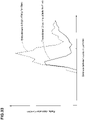
- the radial distribution function is a function which expresses a probability density that another center F-particle 4c can exist at a distance r from a certain center F-particle 4c ( Fig. 3 ).
- the distance r is that between the centers of the center F-particles 4c.
- the dispersion state of the filler models 3 is obtained by computing the radial distribution functions with respect to only the center F-particles 4c. Therefore, it is possible to control an increase in the computational cost.
- the structure of the high-polymer material model 11 (shown in Fig. 17 ) can be effectively relaxed so as to simulate a structure of an actual high-polymer material.
- the dispersion of filler contained in a high-polymer material is estimated, using the filler models 3 and the polymer models 5 disposed in the virtual space 9.
- the high-polymer material is not limited to this type.
- the high-polymer material can be a high-polymer material further containing a coupling agent for coupling the filler with the polymer as follows.
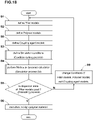
- Fig. 18 is a flow chart of the simulation method according to a second embodiment of the present invention.
- the process S1for defining filler models 3 and the process S2 for defining the polymer models 5 are performed.
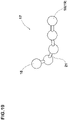
- FIG. 19 is a diagram showing a coupling agent model 17.
- the coupling agent model 17 is a particle model made up of at least one, in this example, a plurality of C-particles 18.
- C-particle means a particle of a coupling agent model 17.
- the C-particles 18 are each defied as a sphere having a certain diameter.
- each coupling agent model 17 has a three-dimensional straight-chain structure.
- the number of the C-particles 18 of each coupling agent model 17 is smaller than the number of the P-particle 6 of a polymer model 5 in order to simulate the coupling agent having a molecular weight smaller than that of a molecular chain of the high-polymer material.
- the coupling agent models 17 are numerical data processable with the computer 1 including the mass, volume, diameter, initial coordinate values and the like of each C-particle 18 and stored in the computer 1.
- simulation conditions are defined.
- Fig. 20 is a flow chart of the condition setting process S3 according to the second embodiment.
- potentials U are defined between the C-particles 18 and the F-particles 4c and 4s, and between the C-particles 18 and the P-particles 6a and 6b.
- the potential U is defined by the above-mentioned expression (1).
- Fig. 21 is a diagram for explaining the potentials relating to the C-particles 18.
- potentials U11 - U14 are defined as follows.
- the coefficient a ij for each potential U11-U14 is defined as follows.
- the reason for setting the same value to the potentials U11-U14 is to even the repulsive force of the coupling agent model 17 exerted on the filler model 3 and the repulsive force of the coupling agent model 17 exerted on the polymer model 5, namely, to simulate a coupling agent in which the affinity for the filler is the same as the affinity for the polymer.
- the coefficients a ij for the potentials U11-U14 are set to different values in order to simulate a coupling agent in which the affinity for the filler is different from the affinity for the polymer, for example as follows.
- the repulsive force between the filler model 3 and the coupling agent model 17 can be smaller than the repulsive force between the polymer model 5 and the coupling agent model 17, and the affinity of the coupling agent model 17 becomes higher for the filler model 3 than the polymer model.
- cutoff distance r c in the expression (1) is set as follows.
- the cutoff distance r c of the potential U11 relating to the center F-particle 4c of the filler model 3 is set to be larger than the cutoff distance r c of the potential U12 relating to the surface F-particles 4s of the filler model 3, and the cutoff distance r c of the potential U11 is set to be larger than the summation (r c + Lc) of the cutoff distance r c of the potential U12 and the interparticle distance Lc (see Fig. 7 ) between the surface F-particles 4s and the center F-particle 4c. Therefore, the filler model 3 can exert the potential U11 ( Fig. 21 ) relating to the center F-particle 4c prior to the potential U12 relating to the surface F-particles 4s.
- the center F-particle 4c is expressed by the sphere having the certain diameter, it is possible to exert the potential U11 radially. Therefore, in the simulation process S4, the filler model 3 can be treated as a sphere approximate to the actual filler, and the simulation accuracy can be improved.
- the virtual space show in Fig. 8 employed in the first embodiment can be employed in the second embodiment as shown in Fig. 22 .
- Fig. 23 is a flow chart of the simulation process S4 in the second embodiment.
- the filler restraining process S41 for restraining the motion of each of the F-particles 4c and 4s (shown in Fig. 22 ) is performed in the same way as in the first embodiment.
- the conditions such as the numbers of the F-particles 4c and 4s, P-particles 6a and 6b and C-particles 18 and the volume and temperature of the virtual space 9 are kept unchanged.
- the polymer models 5 and the coupling agent models 17 can be effectually distributed.
- the number of steps of the molecular dynamics calculation is preferably set to not less than 1000 if the time interval of one step is 0.05[ ⁇ ].
- Fig. 24(a) and Fig. 24(b) are diagrams showing the P-particles 6 and the C-particles 18 before bound and after bound, respectively.
- a P-particle 6 and a C-particle 18 are bound with each other via a link 20 when the interparticle distance therebetween becomes a predetermined value L3 or less to simulate a chemical bond between the coupling agent and the polymer.
- the predetermined value L3 is 0 % to 200 % of the cutoff distance r C ( Fig. 7 ) for the potential relating to the concerned C-particle 18.
- the coupling agent model 17 is bound with only one P-particle 6 of which interparticle distance is not more than the other(s), which usually has the smallest interparticle distance Lp in order that the forces of a plurality of P-particles 6 are not accumulated on one C-particle 18, and thereby to avoid calculation failure.
- each bonding-target F-particle 15 selected from a plurality of the F-particles 4 is bound with a bonding-target P-particle 16 selected from a plurality of the P-particles 6 via a link and/or bound with a bonding-target C-particle 19 selected from a plurality of the C-particle 18 via a link.
- the bonding-target F-particle(s) 15 may be arbitrarily selected from the F-particles 4 of each filler model 3.
- the eight F-particles 4 or the apex F-particles 7 are the bonding-target F-particles 15.
- the bonding-target P-particle(s) 16 may be arbitrarily selected from the P-particles 6 of each polymer model 5.
- one P-particle 6 positioned at the almost center in the length of the straight chain arrangement of the P-particles 6 of each polymer model 5 is the bonding-target P-particle 16.
- one P-particle 18 positioned at one end of the straight chain arrangement of the P-particles 18 of each coupling agent model 17 is selected as the bonding-target C-particle 19.
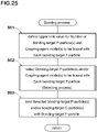
- Fig. 25 is a flow chart of the bonding process S54 in the second embodiment.
- the upper limit value Ns is determined depending on
- the upper limit value Ns is defined by the following expression (3).
- Ns Na + Nc / Nb + 1
- the total number Na is equal to the total number (in this example, 1000) of the polymer models 5 disposed in the virtual space 9.
- the total number Nc is equal to the total number of the bonding-target C-particles 19 disposed in the virtual space 9, namely, 1000, since each coupling agent model 17 has a single bonding-target C-particle 19 as shown in Fig. 19 .
- the (Na+Nc)/Nb means the number of the particles (16, 19) per one bonding-target F-particle 15 when the bonding-target P-particles 16 and the bonding-target C-particles 19 are evenly bound with the bonding-target F-particles 15.
- the [ (Na+Nc)/Nb+1 ] means an integer obtained by rounding up the value (Na+Nc)/Nb.
- the bonding-target P-particle(a) 16 and/or bonding-target C-particle(s) 19 to be bound with each bonding-target F-particle 15 are selected.
- Fig. 26 is a flow chart of the selecting process 562.
- each of the bonding-target P-particles 16 and bonding-target C-particles 19 is associated with one bonding-target F-particle 15 to which interparticle distance Lp is smallest. (1st process S71)
- Fig. 27 is a diagram for explaining this process S71.
- the interparticle distance Lp is the distance between the centers of the particles concerned.
- a first bonding-target F-particle 15a and a second bonding-target F-particle 15b are the bonding-target F-particles 15.
- first bonding-target F-particle 15a As to the first bonding-target F-particle 15a, three bonding-target P-particles 16 and two bonding-target C-particles 19 are associated therewith.
- the three bonding-target P-particles 16 are a first bonding-target P-particle 16a, a second bonding-target P-particle 16b, and a third bonding-target P-particle 16c in the ascending order of the interparticle distance Lp from the bonding-target F-particle 15a.
- the two bonding-target C-particles 19 are a first bonding-target C-particle 19a, and a second bonding-target C-particle 19b in the ascending order of the interparticle distance Lp from the bonding-target F-particle 15a.
- a single bonding-target P-particle 16 (referred to as the fourth bonding-target P-particle 16d) is associated therewith.
- the bonding-target P-particle(s) 16 and/or bonding-target C-particle(s) 19 to be bound with each bonding-target F-particle 15 are selected from the bonding-target P-particle(s) 16 and/or the bonding-target C-particle(s) 19 associated with the concerned bonding-target F-particle 15.
- the selection is made in the ascending order of the interparticle distance Lp so that the sum (Sa+Sb) of the number Sa of the selected bonding-target P-particle(s) 16 and the number Sb of the selected bonding-target C-particle(s) 19 does not exceed the upper limit value Ns.
- Fig. 28 is a diagram for explaining the process S72.
- the upper limit value Ns is 3.
- the number of the selected particles (16, 19) is equal to Ns, and the first bonding-target P-particle 16a, the second bonding-target P-particle 16b, and the first bonding-target C-particle 19a are selected.
- the selected particles (16a, 16b and 19a) are defined as particles to be bound with the first bonding-target F-particle 15a.
- Fig. 28 indicated by a solid line instead of the above-mentioned chain double-dashed line ( Fig. 27 ) is a selected association.
- the not-selected particles (16c and 19b) are defined as particles not to be bound with the first bonding-target F-particle 15a.
- the fourth bonding-target P-particle 16d is defined as a particle to be bound with the second bonding-target F-particle 15b.
- the bonding-target P-particle(s) 16 and/or bonding-target C-particle(s) 19 is/are selected so that the number of the bonding-target P-particle(s) 16 and/or bonding-target C-particle(s) 19 to be bound with each bonding-target F-particle 15 does not exceed the upper limit value Ns.
- each of the bonding-target P-particles 16 and bonding-target C-particles 19 not selected in the 2nd process S72 is associated with another bonding-target F-particle 15.
- Fig. 29 is a diagram for explaining this process S73.
- the third bonding-target P-particle 16c and the second bonding-target C-particle 19b are the concerned not-selected particle (16, 19).
- the second bonding-target F-particle 15b is the searched-out bonding-target F-particle 15.
- the third bonding-target P-particle 16c and the second bonding-target C-particle 19b are associated with the second bonding-target F-particle 15b.
- the bonding-target P-particle(s) 16 and/or bonding-target C-particle(s) 19 to be bound with each bonding-target F-particle 15 is(are) selected from the bonding-target P-particle(s) 16 and/or bonding-target C-particle(s) 19 associated, through the third process S73, with the concerned bonding-target F-particle 15.
- the selection is made in the ascending order of the interparticle distance Lp so that the sum (Sa+Sb) of the number Sa of the selected bonding-target P-particle(s) 16 and the number Sb of the selected bonding-target C-particle(s) 19 satisfies the upper limit value Ns, namely, does not render the total number of the resultant bound particles over the upper limit value Ns.
- Fig. 30 is a diagram for explaining the fourth process S74.
- the third bonding-target P-particle 16c and the second bonding-target C-particle 19b are associated with the second bonding-target F-particle 15b with which the single bonding-target P-particle 16d has already been bound as shown in Fig. 29 .
- the third bonding-target P-particle 16c and the second bonding-target C-particle 19b are each defined as a particle to be bound with the second bonding-target F-particle 15b.
- each of the P-particle(s) 16 and/or the C-particle(s) 19 to which interparticle distance Lp is the third smallest or more, is not defined as a particle to be bound with the second bonding-target F-particle 15b.
- the bonding-target P-particle(s) 16 and bonding-target C-particle(s) 19 to be bound with each bonding-target F-particle 15 are selected from the bonding-target P-particle(s) 16 and/or the bonding-target C-particle(s) 19 associated through the third process S73 so that the sum (Sa+Sb) does not render the total number of the resultant bound particles over the upper limit value Ns.
- bonding-target P-particle(s) 16 and/or bonding-target C-particle(s) 19 selected in the bonding process S46 are bound with the bonding-target F-particle 15.
- Fig. 31 is a diagram for explaining the process 563.
- each selected bonding-target P-particle 16 is bound with the bonding-target F-particle 15 via a link 22 so that the filler models 3 and the polymer models 5 can simulate chemical bond between the filler and the polymer.
- each selected bonding-target C-particle 19 is bound with the bonding-target F-particle 15 via a link 22 so that the filler models 3 and the coupling agent models 17 can simulate chemical bond between the filler and the coupling agent.
- the Newton's equation of motion is applied to all of the filler models 3, the polymer models 5 and the coupling agent models 17, on the assumption that they accord with the classical dynamics for a specified period of time in the virtual space 9.
- the filler models 3, the polymer models 5 and the coupling agent models 17 are distributed within the virtual space 9 as shown in Fig. 17 .
- the sum (Sa+Sb) of the number Sa of the bonding-target P-particle(s) 16 to be bound therewith and the number Sb of the bonding-target C-particle(s) 19 to be bound therewith is set to a value not more than the predetermined upper limit value Ns. Therefore, it is possible to prevent the occurrence of large variation in the number of the P-particle(s) 6 and C-particle(s) 18 bound with each F-particle 4.
- the upper limit value Ns is defined so as to satisfy the expression (3), based on the number of the particles (16, 19) per one bonding-target F-particle 15 when the bonding-target P-particles 16 and the bonding-target C-particles 19 are evenly bound with the bonding-target F-particles 15, the bonding-target P-particles 16 and the bonding-target C-particles 19 can be evenly bound with the bonding-target F-particles 15, and it is possible to prevent an excessive increase in the summation of the forces exerted on each bonding-target F-particle 15 during the molecular dynamics calculation.
- the bonding-target F-particles 15 are only the apex F-particles 7 disposed at the apexes 13a of the polyhedron 13 (shown in Fig. 3 ), it is possible to provide a space between the bonding-target P-particle(s) 16 or bonding-target C-particle(s) 19 bound with a bonding-target F-particle 15 and the bonding-target P-particle(s) 16 or bonding-target C-particle(s) 19 bound with an adjacent bonding-target F-particle 15. Thereby, it is possible to prevent the interaction between the bonding-target P-particle(s) 16 and/or bonding-target C-particle(s) 19 from becoming increased, and it is possible to stably perform the molecular dynamics calculation.
- a structurally-relaxed high-polymer material model 11 in which the filler models 3 and the polymer models 5 are effectually distributed, can be defined.
- the number of steps of the molecular dynamics calculation performed in the process S55 is preferably not less than 1000, more preferably not less than 5000 but preferably not more than 1000000 if the time interval of one step is 0.05[ ⁇ ].
- the radial distribution function is computed with respect to the center F-particle 4c of each filler model 3, and it is checked with the computer 1 whether the results of the radial distribution functions are within the predetermined permissible limits or not.
- the structure of the high-polymer material model 11 (shown in Fig. 17 ) can be effectively relaxed to simulate a structure of an actual high-polymer material.
- the structures of the filler models 3 and the polymer models 5 and the potentials can be arbitrarily defined, therefore, it is possible to estimate the properties and performances of a nonexistent unknown high-polymer material.
- Each of a simulation method as Embodiment 1 and a simulation method as Comparative example 1 was executed thirty times in order to check whether or not calculation failure occured during the molecular dynamics calculation.
- the numbers of the C-particles and the coefficients a ij for the potentials U11 to U14 were as follows.
- the affinity of the C-particle for the F-particle was defined as being higher than the affinity of C-particle for the P-particle.
- the radial distribution of Embodiment 2 is smaller than the radial distribution of Embodiment 3, which means that the dispersion of the filler models of Embodiment 2 was better than that of the filler models of Embodiment 3.
- the simulation method according to the present invention can accurately simulate and estimate the influence of the chain length of the coupling agent on the dispersion of the filler.
- the radial distribution of Embodiment 2 is smaller than the radial distribution function of Embodiment 4, which means that the dispersion of the filler models of Embodiment 2 was better than that of the filler models of Embodiment 4.
- the simulation method according to the present invention can accurately simulate and estimate the influence of the interaction of the coupling agent on the dispersion of the filler.
Landscapes
- Engineering & Computer Science (AREA)
- Theoretical Computer Science (AREA)
- Physics & Mathematics (AREA)
- Computing Systems (AREA)
- Bioinformatics & Cheminformatics (AREA)
- Bioinformatics & Computational Biology (AREA)
- Chemical & Material Sciences (AREA)
- Life Sciences & Earth Sciences (AREA)
- Crystallography & Structural Chemistry (AREA)
- Computer Hardware Design (AREA)
- Evolutionary Computation (AREA)
- Geometry (AREA)
- General Engineering & Computer Science (AREA)
- General Physics & Mathematics (AREA)
- Management, Administration, Business Operations System, And Electronic Commerce (AREA)
Claims (7)
- Simulationsverfahren zum Schätzen der Dispersion von Füllstoff, der in einem hochpolymeren Material enthalten ist, unter Verwendung eines Computers, umfassend:einen Prozess zum Definieren von Füllstoffmodellen des Füllstoffes, wobei jedes Füllstoffmodell ein numerisches Modell ist, das aus einer Mehrzahl an F-Partikeln aufgebaut ist,einen Prozess zum Definieren von Polymermodellen des hochpolymeren Materials, wobei jedes Polymermodell ein numerisches Modell ist, das aus einer Mehrzahl an P-Partikeln aufgebaut ist, undeinen Simulationsprozess zum Ausführen einer Molekulardynamikrechnung unter Verwendung der in einem vorgegebenen virtuellen Raum angeordneten Füllstoffmodelle und Polymermodelle,wobei der Simulationsprozess einen Bindungsprozess zum Binden aus den P-Partikeln ausgewählter Bindungs-Ziel-P-Partikel an aus den F-Partikeln ausgewählte Bindungs-Ziel-F-Partikel umfasst, wobei die Anzahl der/des an jedes Bindungs-Ziel-F-Partikel zu bindenden Bindungs-Ziel-P-Partikel(s) einen vorgegebenen oberen Grenzwert Su einhält, wobeider obere Grenzwert Su, die Gesamtanzahl Na der in dem virtuellen Raum vorhandenen Bindungs-Ziel-P-Partikel und die Gesamtanzahl Nb der in dem virtuellen Raum vorhandenen Bindungs-Ziel-F-Partikel dem folgenden Ausdruck genügen:

- Simulationsverfahren nach Anspruch 1, wobei der Bindungsprozess umfasst:einen Prozess zum Definieren des oberen Grenzwerts Su,einen Auswahlprozess zum Auswählen des/der an jeden Bindungs-Ziel-F-Partikel zu bindenden Bindungs-Ziel-P-Partikel(s), undeinen Prozess zum Binden des/der ausgewählten Bindungs-Ziel-P-Partikel(s) an das jeweilige Bindungs-Ziel-F-Partikel.
- Simulationsverfahren nach Anspruch 2, wobei
der Auswahlprozess enthält:einen 1. Prozess zum Verknüpfen jedes Bindungs-Ziel-P-Partikels mit einem Bindungs-Ziel-F-Partikel, zu dem der Zwischenpartikelabstand am kleinsten ist,einen 2. Prozess zum Auswählen des/der an jedes Bindungs-Ziel-F-Partikel zu bindenden Bindungs-Ziel-P-Partikel(s) aus einer Gruppe des/der mit dem jeweiligen Bindungs-Ziel-F-Partikel verknüpften Bindungs-Ziel-P-Partikel(s) in aufsteigender Reihenfolge des Zwischenpartikelabstands, um den oberen Grenzwert Su einzuhalten,einen dritten Prozess zum Verknüpfen jedes nicht im 2. Prozess ausgewählten Bindungs-Ziel-P-Partikels mit einem Bindungs-Ziel-F-Partikel, zu dem der Zwischenpartikelabstand am zweitkleinsten ist, nach demjenigen Bindungs-Ziel-F-Partikel, zu dem der Zwischenpartikelabstand am kleinsten ist, undeinen vierten Prozess zum Auswählen des/der an jedes Bindungs-Ziel-F-Partikel zu bindenden Bindungs-Ziel-P-Partikel(s) aus einer Gruppe des/der im dritten Prozess verknüpften Bindungs-Ziel-P-Partikel(s),in aufsteigender Reihenfolge des Zwischenpartikelabstands,um den oberen Grenzwert Su einzuhalten, undder dritte Prozess und der vierte Prozess wiederholt werden, bis alle Bindungs-Ziel-P-Partikel für die Bindungs-Ziel-F-Partikel ausgewählt sind. - Simulationsverfahren zum Schätzen der Dispersion von Füllstoff, der in einem hochpolymeren Material enthalten ist, zusammen mit einem Kopplungsmittel zum Koppeln des Füllstoffes mit Polymer, unter Verwendung eines Computers, umfassend:einen Prozess zum Definieren von Füllstoffmodellen des Füllstoffes, wobei jedes Füllstoffmodell ein numerisches Modell ist, das aus einer Mehrzahl an F-Partikeln aufgebaut ist,einen Prozess zum Definieren von Polymermodellen des hochpolymeren Materials, wobei jedes Polymermodell ein numerisches Modell ist, das aus einer Mehrzahl an P-Partikeln aufgebaut ist, undeinen Prozess zum Definieren von Kopplungsmittelmodellen des Kopplungsmittels, wobei jedes Kopplungsmittelmodell ein numerisches Modell ist, das aus mindestens einem C-Partikel aufgebaut ist,einen Simulationsprozess zum Ausführen einer Molekulardynamikrechnung unter Verwendung der in einem vorgegebenen virtuellen Raum angeordneten Füllstoffmodelle, Kopplungsmittelmodelle und Polymermodelle,wobei der Simulationsprozess einen Bindungsprozess umfasst, in welchem aus den P-Partikeln ausgewählte Bindungs-Ziel-P-Partikel und aus den C-Partikeln ausgewählte Bindungs-Ziel-C-Partikel an aus den F-Partikeln ausgewählte Bindungs-Ziel-F-Partikel gebunden werden, wobei
die Anzahl der/des an jedes Bindungs-Ziel-F-Partikel zu bindenden Bindungs-Ziel-P-Partikel(s) und/oder Bindungs-Ziel-C-Partikel(s) einen vorgegebenen oberen Grenzwert Ns einhält, wobeider obere Grenzwert Ns, die Gesamtanzahl Na der in dem virtuellen Raum vorhandenen Bindungs-Ziel-P-Partikel, die Gesamtanzahl Nb der in dem virtuellen Raum vorhandenen Bindungs-Ziel-F-Partikel und die Gesamtanzahl Nc der in dem virtuellen Raum vorhandenen Bindungs-Ziel-C-Partikel dem folgenden Ausdruck genügen:
- Simulationsverfahren nach Anspruch 4, wobei
der Bindungsprozess umfasst:einen Prozess zum Definieren des oberen Grenzwerts Ns,einen Auswahlprozess zum Auswählen des/der an jedes Bindungs-Ziel-F-Partikel zu bindenden Bindungs-Ziel-P-Partikel(s) und/oder Bindungs-Ziel-C-Partikel(s), undeinen Prozess zum Binden des/der ausgewählten Bindungs-Ziel-P-Partikel(s) und/oder Bindungs-Ziel-C-Partikel(s) an das jeweilige Bindungs-Ziel-F-Partikel. - Simulationsverfahren nach Anspruch 5, wobei
der Auswahlprozess umfasst:einen 1. Prozess zum Verknüpfen jedes Bindungs-Ziel-P-Partikels mit einem Bindungs-Ziel-F-Partikel, zu dem der Zwischenpartikelabstand am kleinsten ist, und zum Verknüpfen jedes Bindungs-Ziel-C-Partikels mit einem Bindungs-Ziel-F-Partikel, zu dem der Zwischenpartikelabstand am kleinsten ist,einen 2. Prozess zum Auswählendes/der an jedes Bindungs-Ziel-F-Partikel zu bindenden Bindungs-Ziel-P-Partikel(s) und/oder Bindungs-Ziel-C-Partikel(s) aus den verknüpften Bindungs-Ziel-P-Partikel(n) und/oder Bindungs-Ziel-C-Partikel(n) in aufsteigender Reihenfolge des Zwischenpartikelabstands,um den oberen Grenzwert Ns einzuhalten,einen dritten Prozess zumVerknüpfen jedes nicht im 2. Prozess ausgewählten Bindungs-Ziel-P-Partikels mit einem Bindungs-Ziel-F-Partikel, zu dem der Zwischenpartikelabstand am zweitkleinsten ist, nach demjenigen Bindungs-Ziel-F-Partikel, zu dem der Zwischenpartikelabstand am kleinsten ist, undVerknüpfen jedes nicht im 2. Prozess ausgewählten Bindungs-Ziel-C-Partikels mit einem Bindungs-Ziel-F-Partikel, zu dem der Zwischenpartikelabstand am zweitkleinsten ist, nach demjenigen Bindungs-Ziel-F-Partikel, zu dem der Zwischenpartikelabstand am kleinsten ist, undeinen vierten Prozess zum Auswählen des/der an jedes Bindungs-Ziel-F-Partikel zu bindenden Bindungs-Ziel-P-Partikel(s) und/oder Bindungs-Ziel-C-Partikel(s) aus dem/den im dritten Prozess verknüpften Bindungs-Ziel-P-Partikel(n) und/oder Bindungs-Ziel-C-Partikel(n) in aufsteigender Reihenfolge des Zwischenpartikelabstands, um den oberen Grenzwert Ns einzuhalten, undder dritte Prozess und der vierte Prozess wiederholt werden, bis alle Bindungs-Ziel-P-Partikel und Bindungs-Ziel-C-Partikel für die Bindungs-Ziel-F-Partikel ausgewählt sind. - Simulationsverfahren nach einem der Ansprüche 1 bis 6, wobei
die F-Partikel jedes Füllstoffmodells diejenigen umfassen, die an Spitzen eines Polyeders angeordnet sind, und die Bindungs-Ziel-F-Partikel die an den Spitzen angeordneten F-Partikel sind.
Applications Claiming Priority (2)
| Application Number | Priority Date | Filing Date | Title |
|---|---|---|---|
| JP2014086665 | 2014-04-18 | ||
| JP2014231208A JP6335101B2 (ja) | 2014-04-18 | 2014-11-14 | 高分子材料のシミュレーション方法 |
Publications (2)
| Publication Number | Publication Date |
|---|---|
| EP2933744A1 EP2933744A1 (de) | 2015-10-21 |
| EP2933744B1 true EP2933744B1 (de) | 2022-10-12 |
Family
ID=52875590
Family Applications (1)
| Application Number | Title | Priority Date | Filing Date |
|---|---|---|---|
| EP15163451.6A Active EP2933744B1 (de) | 2014-04-18 | 2015-04-14 | Simulationsverfahren für hochpolymermaterial |
Country Status (3)
| Country | Link |
|---|---|
| US (1) | US20150302180A1 (de) |
| EP (1) | EP2933744B1 (de) |
| JP (1) | JP6335101B2 (de) |
Families Citing this family (9)
| Publication number | Priority date | Publication date | Assignee | Title |
|---|---|---|---|---|
| JP6746971B2 (ja) * | 2016-03-11 | 2020-08-26 | 横浜ゴム株式会社 | 複合材料の解析方法及び複合材料の解析用コンピュータプログラム |
| JP6759733B2 (ja) * | 2016-06-10 | 2020-09-23 | 横浜ゴム株式会社 | 凝集塊モデルの作成方法、凝集塊モデルの作成用コンピュータプログラム、複合材料の解析方法及び複合材料の解析用コンピュータプログラム |
| JP6891549B2 (ja) * | 2017-03-08 | 2021-06-18 | 横浜ゴム株式会社 | 複合材料の解析方法及び複合材料の解析用コンピュータプログラム |
| JP6458097B1 (ja) * | 2017-08-04 | 2019-01-23 | 住友ゴム工業株式会社 | 高分子材料の粗視化分子動力学シミュレーション方法 |
| JP7087300B2 (ja) * | 2017-08-09 | 2022-06-21 | 住友ゴム工業株式会社 | 高分子材料のシミュレーション方法及び高分子材料の破壊特性評価方法 |
| JP7105628B2 (ja) * | 2018-06-20 | 2022-07-25 | Toyo Tire株式会社 | フィラー充填架橋高分子モデルを生成する方法、システム及びプログラム |
| JP7136617B2 (ja) * | 2018-07-25 | 2022-09-13 | Toyo Tire株式会社 | 複数の粒子から成る凝集体モデルを生成する方法、システム及びプログラム |
| CN109994159B (zh) * | 2019-03-22 | 2022-03-25 | 华南理工大学 | 一种硅化程度对硅结合重金属离子强度影响的模拟方法 |
| JP2023158301A (ja) * | 2022-04-18 | 2023-10-30 | Toyo Tire株式会社 | 架橋高分子モデルの生成方法、システム、及びプログラム |
Family Cites Families (9)
| Publication number | Priority date | Publication date | Assignee | Title |
|---|---|---|---|---|
| EP1526468B1 (de) * | 2003-10-17 | 2009-09-30 | Sumitomo Rubber Industries Limited | Verfahren zur Simulation von viskoelastischem Material |
| US8554527B2 (en) * | 2011-04-08 | 2013-10-08 | Japan Agency For Marine-Earth Science And Technology | Particle simulator and method of simulating particles |
| JP5548180B2 (ja) * | 2011-11-24 | 2014-07-16 | 住友ゴム工業株式会社 | 高分子材料のシミュレーション方法 |
| JP5427260B2 (ja) * | 2012-03-08 | 2014-02-26 | 住友ゴム工業株式会社 | 高分子材料のシミュレーション方法 |
| JP5602190B2 (ja) * | 2012-06-08 | 2014-10-08 | 住友ゴム工業株式会社 | 高分子材料のシミュレーション方法 |
| JP5592921B2 (ja) * | 2012-06-21 | 2014-09-17 | 住友ゴム工業株式会社 | 高分子材料のシミュレーション方法 |
| JP5530480B2 (ja) * | 2012-07-05 | 2014-06-25 | 住友ゴム工業株式会社 | 高分子材料のシミュレーション方法 |
| US20140067350A1 (en) * | 2012-08-31 | 2014-03-06 | Sumitomo Rubber Industries, Ltd. | Method for simulating polymer material |
| JP6690206B2 (ja) * | 2014-12-26 | 2020-04-28 | 株式会社デンソー | 樹脂成形体およびその製造方法 |
-
2014
- 2014-11-14 JP JP2014231208A patent/JP6335101B2/ja active Active
-
2015
- 2015-04-14 EP EP15163451.6A patent/EP2933744B1/de active Active
- 2015-04-17 US US14/689,263 patent/US20150302180A1/en not_active Abandoned
Non-Patent Citations (1)
| Title |
|---|
| STARR FRANCIS W. ET AL: "Molecular Dynamics Simulation of a Polymer Melt with a Nanoscopic Particle", MACROMOLECULES, vol. 35, no. 11, 21 May 2002 (2002-05-21), Washington DC United States, pages 4481 - 4492, XP055800535, ISSN: 0024-9297, Retrieved from the Internet <URL:https://pubs.acs.org/doi/pdf/10.1021/ma010626p> DOI: 10.1021/ma010626p * |
Also Published As
| Publication number | Publication date |
|---|---|
| US20150302180A1 (en) | 2015-10-22 |
| JP2015212925A (ja) | 2015-11-26 |
| JP6335101B2 (ja) | 2018-05-30 |
| EP2933744A1 (de) | 2015-10-21 |
Similar Documents
| Publication | Publication Date | Title |
|---|---|---|
| EP2933744A1 (de) | Simulationsverfahren für hochpolymermaterial | |
| Nadachowska‐Brzyska et al. | Navigating the temporal continuum of effective population size | |
| Marano et al. | Modified genetic algorithm for the dynamic identification of structural systems using incomplete measurements | |
| JP5871193B2 (ja) | 監視データ分析装置、監視データ分析方法および監視データ分析プログラム | |
| US10839112B2 (en) | Wind simulation device | |
| JP6097130B2 (ja) | 高分子材料のシミュレーション方法 | |
| US9477794B2 (en) | Simulation method for high polymer material | |
| JP5923069B2 (ja) | 高分子材料のシミュレーション方法 | |
| EP2778678B1 (de) | Simulationsverfahren für ein polymermaterial | |
| JP6254325B1 (ja) | 高分子材料の粗視化分子動力学シミュレーション方法 | |
| Rothrock et al. | Human-in-the-loop simulations | |
| JP5602190B2 (ja) | 高分子材料のシミュレーション方法 | |
| Zhao et al. | A new event-driven constant-volume method for solution of the time evolution of particle size distribution | |
| JP6353290B2 (ja) | 高分子材料モデル作成方法 | |
| Forsythe et al. | Divergence-based introgression polarization | |
| JP6776876B2 (ja) | 高分子材料のシミュレーション方法 | |
| JP5530480B2 (ja) | 高分子材料のシミュレーション方法 | |
| JP6962160B2 (ja) | 高分子材料の粗視化分子動力学シミュレーション方法 | |
| JP2020095400A (ja) | シミュレーション装置、シミュレーション方法、及びプログラム | |
| Nasrellah et al. | Particle filters for structural system identification using multiple test and sensor data: a combined computational and experimental study | |
| Vimaladevi et al. | Stability aware software refactoring using hybrid search based techniques | |
| JP6554995B2 (ja) | 高分子材料のシミュレーション方法 | |
| JP7087300B2 (ja) | 高分子材料のシミュレーション方法及び高分子材料の破壊特性評価方法 | |
| Duduială et al. | Nonlinear breathing modes at a defect site in DNA | |
| Barrandeguy et al. | Microsatellites as a tool for the study of microevolutionary process in native forest trees |
Legal Events
| Date | Code | Title | Description |
|---|---|---|---|
| PUAI | Public reference made under article 153(3) epc to a published international application that has entered the european phase |
Free format text: ORIGINAL CODE: 0009012 |
|
| AK | Designated contracting states |
Kind code of ref document: A1 Designated state(s): AL AT BE BG CH CY CZ DE DK EE ES FI FR GB GR HR HU IE IS IT LI LT LU LV MC MK MT NL NO PL PT RO RS SE SI SK SM TR |
|
| AX | Request for extension of the european patent |
Extension state: BA ME |
|
| 17P | Request for examination filed |
Effective date: 20160421 |
|
| RBV | Designated contracting states (corrected) |
Designated state(s): AL AT BE BG CH CY CZ DE DK EE ES FI FR GB GR HR HU IE IS IT LI LT LU LV MC MK MT NL NO PL PT RO RS SE SI SK SM TR |
|
| STAA | Information on the status of an ep patent application or granted ep patent |
Free format text: STATUS: EXAMINATION IS IN PROGRESS |
|
| 17Q | First examination report despatched |
Effective date: 20210510 |
|
| REG | Reference to a national code |
Ref country code: DE Ref legal event code: R079 Ref document number: 602015081131 Country of ref document: DE Free format text: PREVIOUS MAIN CLASS: G06F0019000000 Ipc: G16C0020300000 |
|
| GRAP | Despatch of communication of intention to grant a patent |
Free format text: ORIGINAL CODE: EPIDOSNIGR1 |
|
| STAA | Information on the status of an ep patent application or granted ep patent |
Free format text: STATUS: GRANT OF PATENT IS INTENDED |
|
| RIC1 | Information provided on ipc code assigned before grant |
Ipc: G16C 20/30 20190101AFI20220425BHEP |
|
| INTG | Intention to grant announced |
Effective date: 20220512 |
|
| RIN1 | Information on inventor provided before grant (corrected) |
Inventor name: UENO, SHINICHI |
|
| GRAS | Grant fee paid |
Free format text: ORIGINAL CODE: EPIDOSNIGR3 |
|
| GRAA | (expected) grant |
Free format text: ORIGINAL CODE: 0009210 |
|
| STAA | Information on the status of an ep patent application or granted ep patent |
Free format text: STATUS: THE PATENT HAS BEEN GRANTED |
|
| AK | Designated contracting states |
Kind code of ref document: B1 Designated state(s): AL AT BE BG CH CY CZ DE DK EE ES FI FR GB GR HR HU IE IS IT LI LT LU LV MC MK MT NL NO PL PT RO RS SE SI SK SM TR |
|
| REG | Reference to a national code |
Ref country code: GB Ref legal event code: FG4D |
|
| REG | Reference to a national code |
Ref country code: CH Ref legal event code: EP |
|
| REG | Reference to a national code |
Ref country code: DE Ref legal event code: R096 Ref document number: 602015081131 Country of ref document: DE |
|
| REG | Reference to a national code |
Ref country code: IE Ref legal event code: FG4D |
|
| REG | Reference to a national code |
Ref country code: AT Ref legal event code: REF Ref document number: 1524666 Country of ref document: AT Kind code of ref document: T Effective date: 20221115 |
|
| REG | Reference to a national code |
Ref country code: LT Ref legal event code: MG9D |
|
| REG | Reference to a national code |
Ref country code: NL Ref legal event code: MP Effective date: 20221012 |
|
| REG | Reference to a national code |
Ref country code: AT Ref legal event code: MK05 Ref document number: 1524666 Country of ref document: AT Kind code of ref document: T Effective date: 20221012 |
|
| PG25 | Lapsed in a contracting state [announced via postgrant information from national office to epo] |
Ref country code: NL Free format text: LAPSE BECAUSE OF FAILURE TO SUBMIT A TRANSLATION OF THE DESCRIPTION OR TO PAY THE FEE WITHIN THE PRESCRIBED TIME-LIMIT Effective date: 20221012 |
|
| PG25 | Lapsed in a contracting state [announced via postgrant information from national office to epo] |
Ref country code: SE Free format text: LAPSE BECAUSE OF FAILURE TO SUBMIT A TRANSLATION OF THE DESCRIPTION OR TO PAY THE FEE WITHIN THE PRESCRIBED TIME-LIMIT Effective date: 20221012 Ref country code: PT Free format text: LAPSE BECAUSE OF FAILURE TO SUBMIT A TRANSLATION OF THE DESCRIPTION OR TO PAY THE FEE WITHIN THE PRESCRIBED TIME-LIMIT Effective date: 20230213 Ref country code: NO Free format text: LAPSE BECAUSE OF FAILURE TO SUBMIT A TRANSLATION OF THE DESCRIPTION OR TO PAY THE FEE WITHIN THE PRESCRIBED TIME-LIMIT Effective date: 20230112 Ref country code: LT Free format text: LAPSE BECAUSE OF FAILURE TO SUBMIT A TRANSLATION OF THE DESCRIPTION OR TO PAY THE FEE WITHIN THE PRESCRIBED TIME-LIMIT Effective date: 20221012 Ref country code: FI Free format text: LAPSE BECAUSE OF FAILURE TO SUBMIT A TRANSLATION OF THE DESCRIPTION OR TO PAY THE FEE WITHIN THE PRESCRIBED TIME-LIMIT Effective date: 20221012 Ref country code: ES Free format text: LAPSE BECAUSE OF FAILURE TO SUBMIT A TRANSLATION OF THE DESCRIPTION OR TO PAY THE FEE WITHIN THE PRESCRIBED TIME-LIMIT Effective date: 20221012 Ref country code: AT Free format text: LAPSE BECAUSE OF FAILURE TO SUBMIT A TRANSLATION OF THE DESCRIPTION OR TO PAY THE FEE WITHIN THE PRESCRIBED TIME-LIMIT Effective date: 20221012 |
|
| PG25 | Lapsed in a contracting state [announced via postgrant information from national office to epo] |
Ref country code: RS Free format text: LAPSE BECAUSE OF FAILURE TO SUBMIT A TRANSLATION OF THE DESCRIPTION OR TO PAY THE FEE WITHIN THE PRESCRIBED TIME-LIMIT Effective date: 20221012 Ref country code: PL Free format text: LAPSE BECAUSE OF FAILURE TO SUBMIT A TRANSLATION OF THE DESCRIPTION OR TO PAY THE FEE WITHIN THE PRESCRIBED TIME-LIMIT Effective date: 20221012 Ref country code: LV Free format text: LAPSE BECAUSE OF FAILURE TO SUBMIT A TRANSLATION OF THE DESCRIPTION OR TO PAY THE FEE WITHIN THE PRESCRIBED TIME-LIMIT Effective date: 20221012 Ref country code: IS Free format text: LAPSE BECAUSE OF FAILURE TO SUBMIT A TRANSLATION OF THE DESCRIPTION OR TO PAY THE FEE WITHIN THE PRESCRIBED TIME-LIMIT Effective date: 20230212 Ref country code: HR Free format text: LAPSE BECAUSE OF FAILURE TO SUBMIT A TRANSLATION OF THE DESCRIPTION OR TO PAY THE FEE WITHIN THE PRESCRIBED TIME-LIMIT Effective date: 20221012 Ref country code: GR Free format text: LAPSE BECAUSE OF FAILURE TO SUBMIT A TRANSLATION OF THE DESCRIPTION OR TO PAY THE FEE WITHIN THE PRESCRIBED TIME-LIMIT Effective date: 20230113 |
|
| REG | Reference to a national code |
Ref country code: DE Ref legal event code: R097 Ref document number: 602015081131 Country of ref document: DE |
|
| PG25 | Lapsed in a contracting state [announced via postgrant information from national office to epo] |
Ref country code: SM Free format text: LAPSE BECAUSE OF FAILURE TO SUBMIT A TRANSLATION OF THE DESCRIPTION OR TO PAY THE FEE WITHIN THE PRESCRIBED TIME-LIMIT Effective date: 20221012 Ref country code: RO Free format text: LAPSE BECAUSE OF FAILURE TO SUBMIT A TRANSLATION OF THE DESCRIPTION OR TO PAY THE FEE WITHIN THE PRESCRIBED TIME-LIMIT Effective date: 20221012 Ref country code: EE Free format text: LAPSE BECAUSE OF FAILURE TO SUBMIT A TRANSLATION OF THE DESCRIPTION OR TO PAY THE FEE WITHIN THE PRESCRIBED TIME-LIMIT Effective date: 20221012 Ref country code: DK Free format text: LAPSE BECAUSE OF FAILURE TO SUBMIT A TRANSLATION OF THE DESCRIPTION OR TO PAY THE FEE WITHIN THE PRESCRIBED TIME-LIMIT Effective date: 20221012 Ref country code: CZ Free format text: LAPSE BECAUSE OF FAILURE TO SUBMIT A TRANSLATION OF THE DESCRIPTION OR TO PAY THE FEE WITHIN THE PRESCRIBED TIME-LIMIT Effective date: 20221012 |
|
| PLBE | No opposition filed within time limit |
Free format text: ORIGINAL CODE: 0009261 |
|
| STAA | Information on the status of an ep patent application or granted ep patent |
Free format text: STATUS: NO OPPOSITION FILED WITHIN TIME LIMIT |
|
| PG25 | Lapsed in a contracting state [announced via postgrant information from national office to epo] |
Ref country code: SK Free format text: LAPSE BECAUSE OF FAILURE TO SUBMIT A TRANSLATION OF THE DESCRIPTION OR TO PAY THE FEE WITHIN THE PRESCRIBED TIME-LIMIT Effective date: 20221012 Ref country code: AL Free format text: LAPSE BECAUSE OF FAILURE TO SUBMIT A TRANSLATION OF THE DESCRIPTION OR TO PAY THE FEE WITHIN THE PRESCRIBED TIME-LIMIT Effective date: 20221012 |
|
| 26N | No opposition filed |
Effective date: 20230713 |
|
| PG25 | Lapsed in a contracting state [announced via postgrant information from national office to epo] |
Ref country code: SI Free format text: LAPSE BECAUSE OF FAILURE TO SUBMIT A TRANSLATION OF THE DESCRIPTION OR TO PAY THE FEE WITHIN THE PRESCRIBED TIME-LIMIT Effective date: 20221012 |
|
| REG | Reference to a national code |
Ref country code: CH Ref legal event code: PL |
|
| GBPC | Gb: european patent ceased through non-payment of renewal fee |
Effective date: 20230414 |
|
| PG25 | Lapsed in a contracting state [announced via postgrant information from national office to epo] |
Ref country code: LU Free format text: LAPSE BECAUSE OF NON-PAYMENT OF DUE FEES Effective date: 20230414 |
|
| REG | Reference to a national code |
Ref country code: BE Ref legal event code: MM Effective date: 20230430 |
|
| PG25 | Lapsed in a contracting state [announced via postgrant information from national office to epo] |
Ref country code: MC Free format text: LAPSE BECAUSE OF FAILURE TO SUBMIT A TRANSLATION OF THE DESCRIPTION OR TO PAY THE FEE WITHIN THE PRESCRIBED TIME-LIMIT Effective date: 20221012 |
|
| PG25 | Lapsed in a contracting state [announced via postgrant information from national office to epo] |
Ref country code: GB Free format text: LAPSE BECAUSE OF NON-PAYMENT OF DUE FEES Effective date: 20230414 |
|
| PG25 | Lapsed in a contracting state [announced via postgrant information from national office to epo] |
Ref country code: MC Free format text: LAPSE BECAUSE OF FAILURE TO SUBMIT A TRANSLATION OF THE DESCRIPTION OR TO PAY THE FEE WITHIN THE PRESCRIBED TIME-LIMIT Effective date: 20221012 Ref country code: LI Free format text: LAPSE BECAUSE OF NON-PAYMENT OF DUE FEES Effective date: 20230430 Ref country code: GB Free format text: LAPSE BECAUSE OF NON-PAYMENT OF DUE FEES Effective date: 20230414 Ref country code: CH Free format text: LAPSE BECAUSE OF NON-PAYMENT OF DUE FEES Effective date: 20230430 |
|
| REG | Reference to a national code |
Ref country code: IE Ref legal event code: MM4A |
|
| PG25 | Lapsed in a contracting state [announced via postgrant information from national office to epo] |
Ref country code: BE Free format text: LAPSE BECAUSE OF NON-PAYMENT OF DUE FEES Effective date: 20230430 |
|
| PG25 | Lapsed in a contracting state [announced via postgrant information from national office to epo] |
Ref country code: IE Free format text: LAPSE BECAUSE OF NON-PAYMENT OF DUE FEES Effective date: 20230414 |
|
| PG25 | Lapsed in a contracting state [announced via postgrant information from national office to epo] |
Ref country code: IE Free format text: LAPSE BECAUSE OF NON-PAYMENT OF DUE FEES Effective date: 20230414 |
|
| PG25 | Lapsed in a contracting state [announced via postgrant information from national office to epo] |
Ref country code: IT Free format text: LAPSE BECAUSE OF FAILURE TO SUBMIT A TRANSLATION OF THE DESCRIPTION OR TO PAY THE FEE WITHIN THE PRESCRIBED TIME-LIMIT Effective date: 20221012 |
|
| PGFP | Annual fee paid to national office [announced via postgrant information from national office to epo] |
Ref country code: FR Payment date: 20240308 Year of fee payment: 10 |
|
| PGFP | Annual fee paid to national office [announced via postgrant information from national office to epo] |
Ref country code: DE Payment date: 20240227 Year of fee payment: 10 |
|
| PG25 | Lapsed in a contracting state [announced via postgrant information from national office to epo] |
Ref country code: BG Free format text: LAPSE BECAUSE OF FAILURE TO SUBMIT A TRANSLATION OF THE DESCRIPTION OR TO PAY THE FEE WITHIN THE PRESCRIBED TIME-LIMIT Effective date: 20221012 |
|
| P01 | Opt-out of the competence of the unified patent court (upc) registered |
Free format text: CASE NUMBER: UPC_APP_109359/2023 Effective date: 20230510 |
|
| PG25 | Lapsed in a contracting state [announced via postgrant information from national office to epo] |
Ref country code: BG Free format text: LAPSE BECAUSE OF FAILURE TO SUBMIT A TRANSLATION OF THE DESCRIPTION OR TO PAY THE FEE WITHIN THE PRESCRIBED TIME-LIMIT Effective date: 20221012 |
|
| PG25 | Lapsed in a contracting state [announced via postgrant information from national office to epo] |
Ref country code: CY Free format text: LAPSE BECAUSE OF FAILURE TO SUBMIT A TRANSLATION OF THE DESCRIPTION OR TO PAY THE FEE WITHIN THE PRESCRIBED TIME-LIMIT; INVALID AB INITIO Effective date: 20150414 |
|
| PG25 | Lapsed in a contracting state [announced via postgrant information from national office to epo] |
Ref country code: HU Free format text: LAPSE BECAUSE OF FAILURE TO SUBMIT A TRANSLATION OF THE DESCRIPTION OR TO PAY THE FEE WITHIN THE PRESCRIBED TIME-LIMIT; INVALID AB INITIO Effective date: 20150414 |
|
| REG | Reference to a national code |
Ref country code: DE Ref legal event code: R119 Ref document number: 602015081131 Country of ref document: DE |
|
| PG25 | Lapsed in a contracting state [announced via postgrant information from national office to epo] |
Ref country code: TR Free format text: LAPSE BECAUSE OF FAILURE TO SUBMIT A TRANSLATION OF THE DESCRIPTION OR TO PAY THE FEE WITHIN THE PRESCRIBED TIME-LIMIT Effective date: 20221012 |
|
| PG25 | Lapsed in a contracting state [announced via postgrant information from national office to epo] |
Ref country code: DE Free format text: LAPSE BECAUSE OF NON-PAYMENT OF DUE FEES Effective date: 20251104 |
|
| PG25 | Lapsed in a contracting state [announced via postgrant information from national office to epo] |
Ref country code: FR Free format text: LAPSE BECAUSE OF NON-PAYMENT OF DUE FEES Effective date: 20250430 |