EP2933106B1 - Imprimante à jet d'encre - Google Patents
Imprimante à jet d'encre Download PDFInfo
- Publication number
- EP2933106B1 EP2933106B1 EP13873226.8A EP13873226A EP2933106B1 EP 2933106 B1 EP2933106 B1 EP 2933106B1 EP 13873226 A EP13873226 A EP 13873226A EP 2933106 B1 EP2933106 B1 EP 2933106B1
- Authority
- EP
- European Patent Office
- Prior art keywords
- housing
- carriage
- suction means
- recording medium
- gas
- Prior art date
- Legal status (The legal status is an assumption and is not a legal conclusion. Google has not performed a legal analysis and makes no representation as to the accuracy of the status listed.)
- Not-in-force
Links
Images


Classifications
-
- B—PERFORMING OPERATIONS; TRANSPORTING
- B41—PRINTING; LINING MACHINES; TYPEWRITERS; STAMPS
- B41J—TYPEWRITERS; SELECTIVE PRINTING MECHANISMS, i.e. MECHANISMS PRINTING OTHERWISE THAN FROM A FORME; CORRECTION OF TYPOGRAPHICAL ERRORS
- B41J29/00—Details of, or accessories for, typewriters or selective printing mechanisms not otherwise provided for
- B41J29/377—Cooling or ventilating arrangements
-
- B—PERFORMING OPERATIONS; TRANSPORTING
- B41—PRINTING; LINING MACHINES; TYPEWRITERS; STAMPS
- B41J—TYPEWRITERS; SELECTIVE PRINTING MECHANISMS, i.e. MECHANISMS PRINTING OTHERWISE THAN FROM A FORME; CORRECTION OF TYPOGRAPHICAL ERRORS
- B41J11/00—Devices or arrangements of selective printing mechanisms, e.g. ink-jet printers or thermal printers, for supporting or handling copy material in sheet or web form
- B41J11/0015—Devices or arrangements of selective printing mechanisms, e.g. ink-jet printers or thermal printers, for supporting or handling copy material in sheet or web form for treating before, during or after printing or for uniform coating or laminating the copy material before or after printing
- B41J11/002—Curing or drying the ink on the copy materials, e.g. by heating or irradiating
- B41J11/0024—Curing or drying the ink on the copy materials, e.g. by heating or irradiating using conduction means, e.g. by using a heated platen
- B41J11/00244—Means for heating the copy materials before or during printing
-
- B—PERFORMING OPERATIONS; TRANSPORTING
- B41—PRINTING; LINING MACHINES; TYPEWRITERS; STAMPS
- B41J—TYPEWRITERS; SELECTIVE PRINTING MECHANISMS, i.e. MECHANISMS PRINTING OTHERWISE THAN FROM A FORME; CORRECTION OF TYPOGRAPHICAL ERRORS
- B41J2/00—Typewriters or selective printing mechanisms characterised by the printing or marking process for which they are designed
- B41J2/005—Typewriters or selective printing mechanisms characterised by the printing or marking process for which they are designed characterised by bringing liquid or particles selectively into contact with a printing material
- B41J2/01—Ink jet
Definitions
- the present invention relates to an inkjet printer.
- an inkjet printer for recording an image or the like by ejecting ink onto a recording medium, such as recording paper and a resin film.
- a recording medium such as recording paper and a resin film.
- various types of inks are used.
- the inks include solvent ink using an organic solvent as a prime solvent, ultraviolet curable ink that is curable due to ultraviolet radiation, and thermosetting ink that is curable due to heat.
- the various types of inks are used depending on intended use.
- the solvent ink using the organic solvent as the prime solvent is excellent in fixability onto a resin film such as a PVC film, thereby achieving an advantage in that a recorded product that is highly resistant to wear can be obtained. It is desired to enhance a drying property of this type of ink.
- this type of ink is ejected under a state in which the recording medium is moderately heated, and also after the recording, the recording medium is moderately heated in order to quickly dry the solvent.
- a platen, a paper guide provided on a front side of the platen, and a paper guide provided on a rear side of the platen are each heated, and owing to the heat, the recording medium may be heated.
- a recording head is also heated, and further the recording head itself generates heat.
- the temperature of the recording head or the ink is changed, the viscosity of the ink is changed accordingly, which adversely affects the ejection performance and the image quality.
- JP 2006-264328 A there is disclosed an inkjet printer using the thermosetting ink that promotes fixing due to heat.
- This device has a structure in which a heater is arranged above the carriage so as to extend along the scanning direction of the carriage. Therefore, the carriage is considerably heated, and hence is required to be cooled. The flow of the air is forcibly formed so as to cool the carriage by the air.
- An earlier European patent application EP 2 933 107 A1 forms a state of the art under Art.54(3)EPC and discloses a structure for allowing the outside air, which is taken into a device of the inkjet printer, to be directly sucked into the carriage, and a structure for preventing the outside air from passing through the carriage.
- the temperature inside the carriage can be effectively decreased.
- mechanisms for exhausting the gas are provided on both sides of a housing, specifically, one mechanism is provided on a side surface of the housing and another mechanism is provided on a rear surface thereof. Thus, unevenness of exhausted gas can be suppressed at the right and left of the housing.
- WO 2012/117611 A1 can be seen as a closest prior art and discloses a structure wherein the external air introduced into the device is directly drawn inside the carriage, so that the temperature within the carriage can be made similar to the temperature of the external air regardless of the temperature in the device, to thereby enable a stable discharge from the inkjet head.
- the external air introduced to the device is exhausted out of the device through a duct located at a position away from a print surface, so as to prevent the decrease of the temperature of the recording medium, and poor discharge of ink from the inkjet head.
- This document shows an inkjet printer comprising following features of claim 1: a recording head with nozzles; a reciprocable carriage therein; a platen for retaining the recording medium, the platen being opposed to a lower surface side of the carriage; conveyance means for recording medium; housing-suction means for sucking a gas from an outside into an inside of the housing, the housing-suction means being arranged on a rear surface of the housing so as to be opposed to a rear surface of the carriage;first exhaust means for exhausting the gas inside the housing to the outside, carriage-suction means for sucking gas, which is sucked by the housing-suction means, into the carriage, the carriage-suction means arranged on the rear surface of the carriage so as to be opposed to the housing-suction means; wherein the housing-suction means has a height along the vertical direction, which is larger than a height of the carriage-suction means along the vertical direction, wherein, when the housing-suction means and the carriage-suction means are arranged
- JP 2006-264328 A The technology described in JP 2006-264328 A is a technology of a method involving applying heat to the ink and the recording medium immediately after the ink is ejected from an ink jet head in order to efficiently dry the ink.
- This type of method is also applicable to the solvent ink.
- the heater is arranged immediately above the ink jet head.
- the carriage including the ink jet head is heated immediately below the heater. Therefore, the temperature of the ink jet head is increased, thus leading to ejection failure. Therefore, in JP 2006-264328 A , there is disclosed a structure in which cooling fans are arranged in parallel to the heater, and the air is blown onto the carriage so as to cool the carriage.
- an air guide is provided on the carriage so as to easily receive the air.
- the cooling fans are installed on both ends of the carriage so that the air flows from a center side of the carriage to both the end sides thereof.
- a system in which the carriage is cooled by cooling water and a structure in which a heat-resistant plate for reflecting light is arranged on top of the carriage. In this manner, the temperature of the carriage is prevented from increasing. In such a case, when the cooling water or the heat-resistant plate is used, there is a problem in that an extra space is required and further the cost increases.
- the fans are fixed above the carriage so as to face the recording medium.
- a discharge port for the sucked air is common to a delivery port for the recording medium, and hence there is a fear in that the air is sent to the recording medium immediately before and after the printing so that the recording medium is excessively cooled.
- the simple generation of air is not fully appropriate.
- an inkjet printer for recording an image on a recording medium by ejecting ink onto the recording medium from a recording head while intermittently conveying the recording medium
- the inkjet printer including: a recording head having a plurality of nozzles, for ejecting ink onto a recording medium from the plurality of nozzles; a carriage having the recording head mounted therein, the carriage being reciprocable in a direction intersecting with a conveyance direction of the recording medium; a platen for retaining the recording medium, the platen being arranged so as to be opposed to a lower surface side of the carriage; a heater provided in the platen, for heating the recording medium; conveyance means for conveying the recording medium; a housing having at least the carriage accommodated therein; housing-suction means for sucking a gas from an outside into an inside of the housing, the housing-suction means being arranged on a rear surface of the housing so as to be opposed to a rear surface of the carriage; first exhaust means for exhaust
- the outside air taken by the device is taken into the carriage.
- the temperature inside the carriage is prevented from increasing, and the outside air not taken into the carriage cools the entire device.
- the exhaust fan discharges the gas to the outside, and hence the recording medium is not cooled in a concentrated manner.
- the temperature of the ink immediately after the landing can be prevented from decreasing, and the drying can be promoted by moderately blowing air onto the recording medium after the printing.
- the air less flows around the nozzle surface of the recording head, thereby preventing reduction of ink landing accuracy, increase of ink mist, and drying of the nozzles.
- FIG. 1 is an explanatory view of arrangement of suction means and exhaust means in an inkjet printer.
- a large number of housing-suction fans 8 serving as housing-suction means for sucking a gas are provided in a rear surface of a housing 11 of an inkjet printer 1.
- the housing-suction fans 8 are arranged along a longitudinal direction of the housing 11.
- the housing-suction fans 8 suck an outside gas, that is, air into the housing 11.
- a Y rail 4 and a platen 5 are also arranged along the longitudinal direction of the housing 11.
- the platen 5 is a flat platen, and a large number of through holes are formed therein.
- a gas in the space is discharged to the outside through a large number of suction fans 10 so as to generate negative pressure, and a recording medium conveyed on the platen 5 is sucked so as to be fixed.
- the gas is exhausted by the suction fans 10 from a part below a front paper guide described later.
- the suction fans 10 are also arranged along the longitudinal direction of the housing 11.
- a carriage 2 movable along the Y rail 4 is provided.
- the carriage 2 has recording heads described later mounted therein, and is reciprocable along the Y rail 4.
- the recording head includes a large number of nozzles so as to eject ink.
- a large number of conveyance rollers 13 for conveying the recording medium are provided on an upstream side of the platen 5 along the conveyance direction of the recording medium.
- the conveyance rollers 13 are arranged along a longitudinal direction of the platen 5 at equal intervals.
- a maintenance unit 12 for the recording heads is provided on one end of the housing 11.
- the maintenance unit 12 includes a wiper for wiping a nozzle surface of the recording head, and a cap for sucking ink while being held in close contact with the nozzle surface.
- the maintenance unit 12 performs maintenance such as cleaning the recording heads, covering the recording heads with the caps when not in use so as to prevent drying of the nozzle surface, and sucking the ink when the nozzles are clogged so as to recover the nozzles.
- a housing side surface-exhaust fan 6 is provided on a side surface of the housing 11 on the maintenance unit 12 side so as to exhaust the gas inside the housing 11 to the outside. Further, a space for turning when the carriage 2 reciprocates is secured on a side of the housing 11, which is opposite to the housing side surface-exhaust fan 6 across the platen 5.
- a housing rear surface-exhaust fan 7 is provided on the rear of the space, that is, the rear surface of the housing 11 so as to exhaust the gas inside the housing 11 to the outside.
- the maintenance unit 12 is provided on the housing side surface-exhaust fan 6 side, and hence the volume of a space in the housing 11 on the housing side surface-exhaust fan 6 side is smaller than the volume of the space in the housing 11 on the housing rear surface-exhaust fan 7 side. Therefore, the fans for exhausting the gas are respectively provided on the side surface on the side having the smaller volume and on the rear surface on the side having the larger volume.
- the flow degree of the gas is equalized as much as possible so that a difference in air resistance in the moving direction when the carriage 2 is moved is reduced. An adverse effect on the image quality caused in the moving direction is reduced.
- Ducts 3 for sucking a gas from an outside into the carriage 2 are respectively formed on both ends of an upper part of the carriage 2.
- the duct 3 has a fan and sucks the gas through the fan.
- the ducts 3 are arranged so as to be reciprocable in a position at a height at which the housing-suction fans 8 are arranged. An outside air sucked by the housing-suction fans 8 can be sucked into the ducts 3 for the purpose of cooling the inside of the carriage by cool air through the suction of the air before the air becomes warmer inside the housing 11.
- FIG. 2 is a sectional view of the inkjet printer.
- the housing-suction fan 8 has a height in a vertical direction larger than a height in the vertical direction of each carriage-suction fan 17, which is approximately twice as large as the height in the vertical direction of the carriage-suction fan 17.
- a large-sized fan is used so as to suck a large amount of the outside air.
- the gas sucked into the housing 11 includes a gas to be sucked into the carriage 2 by the carriage-suction fans 17 and a gas to pass through the outside of the carriage 2.
- the carriage-suction fans 17 are arranged at distal ends of the ducts 3 so as to be opposed to the housing-suction fans 8. With this, fresh outside air can be guided into the ducts 3 so as to cool the inside of the carriage 2.
- the carriage 2 has recording heads 18 mounted therein.
- a plurality of the recording heads 18 are arranged in a depth direction in the drawing sheet.
- the carriage 2 has an discharge port 19 formed in a lower part of a front surface thereof so that the air sucked into the carriage 2 flows toward a cover 22 arranged on a front surface of the housing 11.
- the discharge port 19 is formed along the moving direction of the carriage 2 so as to have a width corresponding to an arrangement position of the recording heads 18.
- the discharge port 19 has an elongated hole shape, which is an elongated hole having a width corresponding to an inside dimension of the carriage 2 in a width direction thereof at the maximum.
- a flat cable 23 and an ink tube 24 are connected to an upper part of the recording head 18.
- the flat cables 23 and the ink tubes 24 respectively extend through the two ducts 3 so as to be directed upward in the vicinity of the carriage-suction fans 17, thereby entering a tube accommodating portion 16.
- the tube accommodating portion 16 accommodates the flat cables 23 and the ink tubes 24 so as to be bent into a U-shape in order to connect the flat cables 23 and the ink tubes 24 extending respectively from a control circuit board and ink tanks arranged in other locations of the housing 11 to the recording heads 18 mounted in the reciprocable carriage 2.
- an air-flow from the ducts 3 are separated into an upper side and a lower side by the flat cables 23 and the ink tubes 24 so as to cool the inside of the carriage 2.
- the air-flow inside the carriage 2 is separated, and thus reflux is less likely to occur between the upper side and the lower side. In this manner, the gas that stagnates inside the carriage 2 can be reduced, with the result that the cooling can be carried out suitably.
- the tube accommodating portion 16 is arranged above the carriage-suction fans 17 and the housing-suction fans 8, and thus the air-flow, which is generated through the suction by the housing-suction fans 8, is not disturbed by the flat cables 23 and the ink tubes 24, with the result that a stable air-flow can be generated.
- the flat cables 23 and the ink tubes 24 are moved along with the movement of the carriage 2, which has been a cause of disturbing the air-flow.
- a roller 20 is provided on a rear surface side of the carriage 2 and is connected to the Y rail 4.
- a front paper guide 14 is provided on a downstream side of the platen 5 along the conveyance direction of the recording medium, and a rear paper guide 15 is provided on the upstream side thereof.
- the conveyance rollers 13 are arranged in a portion between the rear paper guide 15 and the platen 5.
- the recording medium is heated in the rear paper guide 15, and conveyed while being nipped by the conveyance rollers 13. Then, the recording medium is sent to the platen 5, and further delivered along the front paper guide 14.
- a heater is also provided in each of the platen 5 and the front paper guide 14 so as to heat the recording medium. In this manner, drying of ink adhered to the recording medium is promoted.
- the rear paper guide 15 is opposed to a bending portion 21, which is arranged above the rear paper guide 15 and corresponds to a portion at which an end portion of the housing 11 is bent.
- the bending portion 21 is bent toward an inward direction of the housing 11, and further approaches the rear paper guide 15 toward a distal end thereof. Further, the distal end portion of the bending portion 21 is arranged so as to be lower than a flat portion on a surface of the platen 5 in a vertical direction.
- the front paper guide 14 is opposed to a distal end of the cover 22 provided above the front paper guide 14.
- the cover 22 is connected to the housing 11 in a pivotable manner. Further, the cover 22 approaches the front paper guide 14 toward a distal end thereof.
- the front paper guide 14 has a curved surface curved downward toward the downstream side in the conveyance direction of the recording medium. With the cover 22 and the front paper guide 14 configured as described above, the gas inside the housing 11 easily flows along a surface of the front paper guide 14.
- the heater is provided inside the front paper guide 14, and the recording medium is heated by the heater, to thereby promote the drying of the ink adhered to the recording medium.
- the cover 22 is arranged gradually closer to the front paper guide 14 toward the distal end of the cover 22 so as to form an air-flow along the front paper guide 14 in a direction indicated by the arrow 25. Further, the front paper guide 14 is arranged so as to be curved downward.
- the gas discharged from the discharge port 19 is directed to the cover 22.
- the gas blown onto the cover 22 forms an air-flow along the cover 22 in a downward direction, and further flows along the front paper guide 14.
- the gas exhausted from the discharge port 19 is discharged to the outside while being mixed with a gas flowing through the outside of the carriage 2. It is preferred that the gas sucked by the carriage-suction fans 17 flow faster than the gas flowing through the outside of the carriage 2 when discharged from the discharge port 19.
- a gas surrounding the air-flow also flows faster, and hence the gas can be smoothly discharged from a portion between the front paper guide 14 and the cover 22 to the outside.
- the gas sucked into the housing 11 is discharged mainly from the housing side surface-exhaust fan 6, the housing rear surface-exhaust fan 7, a portion between the rear paper guide 15 and the bending portion 21, or a portion between the front paper guide 14 and the cover 22, or through the suction by the platen 5.
- the gas is discharged not only in a specific direction but also in various directions in the device so as not to cool only a specific location or cause the strong air to blow onto the specific location, but generate air-flows that flow out in the various directions.
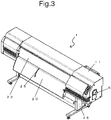
- FIG. 3 is an external view of the inkjet printer.
- the housing 11 is supported by legs 26.
- the legs 26 are fixed to both ends of a lower surface of the housing 11.
- the front paper guide 20 is arranged at a position as high as possible so as to reduce an adverse effect of a floor on the air-flow indicated by the arrow 25.
- the present invention is applicable to an inkjet printer, and particularly applicable to a large-sized inkjet printer.
Claims (4)
- Imprimante jet d'encre (1) pour enregistrer une image sur un support d'enregistrement en projetant de l'encre sur le support d'enregistrement depuis une tête d'enregistrement tout en acheminant par intermittence le support d'enregistrement, l'imprimante jet d'encre (1) comprenant :une tête d'enregistrement (18) ayant une pluralité de buses, pour projeter de l'encre sur un support d'enregistrement à partir de la pluralité de buses ;un chariot (2) dans lequel est montée la tête d'enregistrement (18), le chariot (2) ayant un mouvement de va-et-vient dans une direction coupant une direction d'acheminement du support d'enregistrement ;une platine (5) pour retenir le support d'enregistrement, la platine (5) étant agencée de façon à être opposée à un côté de surface inférieure du chariot (2) ;un élément chauffant prévu dans la platine (5), pour chauffer le support d'enregistrement ;un moyen d'acheminement (13) pour acheminer le support d'enregistrement ;un boîtier (11) dans lequel est logé au moins le chariot (2) ;un moyen d'aspiration de boîtier (8) pour aspirer un gaz depuis l'extérieur jusqu'à l'intérieur du boîtier (11), le moyen d'aspiration de boîtier (8) étant agencé sur une surface arrière du boîtier (11) de façon à être opposé à une surface arrière du chariot (2) ;un premier moyen d'échappement (7) pour échapper le gaz à l'intérieur du boîtier (11) vers l'extérieur, le premier moyen d'échappement (7) étant agencé sur la surface arrière du boîtier (11) ;un second moyen d'échappement (6) pour échapper le gaz à l'intérieur du boîtier (11) vers l'extérieur, le second moyen d'échappement (6) étant agencé sur une surface de côté du boîtier (11) ;un moyen d'aspiration de chariot (17) pour aspirer le gaz, qui est aspiré par le moyen d'aspiration de boîtier (8), dans le chariot (2), le moyen d'aspiration de chariot (17) étant agencé sur la surface arrière du chariot (2) de façon à être opposé au moyen d'aspiration de boîtier (8) ;un guide papier avant (14) pour guider et chauffer le support d'enregistrement, le guide papier avant (14) étant agencé sur un côté aval de la platine (5) dans la direction d'acheminement ; etun couvercle (22) agencé à une distance du guide papier avant (14) et relié au boîtier (11) de sorte qu'une portion d'extrémité distale de celui-ci soit positionnée plus bas dans une direction verticale qu'une surface de la tête d'enregistrement (18), sur laquelle la pluralité de buses est agencée,dans laquelle le moyen d'aspiration de boîtier (8) a une hauteur le long de la direction verticale, qui est plus grande qu'une hauteur du moyen d'aspiration de chariot (17) le long de la direction verticale,dans laquelle, lorsque le moyen d'aspiration de boîtier (8) et le moyen d'aspiration de chariot (17) sont agencés à des positions opposées l'une à l'autre, le gaz aspiré par le moyen d'aspiration de boîtier (8) est aspiré dans le chariot (2) par le moyen d'aspiration de chariot (17), et circule dans le boîtier (11) sans être aspiré par le moyen d'aspiration de chariot (17),dans laquelle le gaz, qui est aspiré dans le chariot (2) par le moyen d'aspiration de chariot (17), est évacué à l'intérieur du boîtier (11) vers le couvercle (22), etdans laquelle le gaz aspiré par le moyen d'aspiration de boîtier (8) est au moins évacué à l'extérieur du boîtier (11) depuis le premier moyen d'échappement (7), le second moyen d'échappement (6), et un débattement entre le guide papier avant (14) et le couvercle (22) ; etdans laquelle une quantité d'aspiration totale par unité de temps du moyen d'aspiration de boîtier (8) pour aspirer le gaz depuis l'extérieur du boîtier (11) est plus grande qu'une quantité d'échappement totale obtenue en sommant un échappement par le premier moyen d'échappement (7) par unité de temps et un échappement par le second moyen d'échappement (6) par unité de temps,dans laquelle une partie du gaz aspiré par le moyen d'aspiration de boîtier (8) est évacuée de façon à traverser une portion entre le guide papier avant (14) et l'extrémité distale du couvercle (22), etdans laquelle le couvercle (22) est agencé de façon à approcher le guide papier avant (14) vers l'extrémité distale de sorte que le gaz évacué soit évacué dans une direction le long du guide papier avant (14).
- Imprimante jet d'encre (1) selon la revendication 1, comprenant en outre :un guide papier arrière (15) pour guider le support d'enregistrement jusqu'à un côté amont de la platine (5) dans la direction d'acheminement, et chauffer le support d'enregistrement ; etune portion de cintrage (21) agencée à une position opposée au guide papier arrière (15), la portion de cintrage (21) étant formée en cintrant une extrémité distale du boîtier (11),dans laquelle la portion de cintrage (21) est agencée de façon à approcher le guide papier arrière (15) vers une extrémité distale de celle-ci, etdans laquelle l'extrémité distale de la portion de cintrage (21) est agencée à une position plus basse que la platine (5) dans la direction verticale.
- Imprimante jet d'encre (1) selon les revendications 1 ou 2, comprenant en outre une unité d'entretien (12) comportant un capuchon pour fermer hermétiquement la tête de jet d'encre sur une partie latérale de la platine (5) sur le côté de second moyen d'échappement de sorte qu'un volume d'un espace vide dans le boîtier (11) sur une partie latérale de la platine (5) sur le côté du premier moyen d'échappement soit plus grand qu'un volume d'un espace vide dans le boîtier (11) sur la partie latérale sur le côté du second moyen d'échappement.
- Imprimante jet d'encre (1) selon l'une quelconque des revendications 1 à 3, comprenant en outre un orifice d'évacuation (19) ayant une forme de trou allongé, qui est formé de façon à être allongé le long d'une direction de déplacement du chariot (2) dans une extrémité inférieure du chariot sur le côté aval dans la direction d'acheminement,
dans laquelle une direction d'évacuation pour l'orifice d'évacuation (19) est dirigée vers le couvercle (22), et
dans laquelle le gaz à l'intérieur du chariot (2), qui est aspiré par le moyen d'aspiration de chariot (17), est évacué vers le couvercle (22).
Applications Claiming Priority (2)
| Application Number | Priority Date | Filing Date | Title |
|---|---|---|---|
| JP2013018755A JP5977183B2 (ja) | 2013-02-01 | 2013-02-01 | インクジェットプリンター |
| PCT/JP2013/078655 WO2014119062A1 (fr) | 2013-02-01 | 2013-10-23 | Imprimante à jet d'encre |
Publications (3)
| Publication Number | Publication Date |
|---|---|
| EP2933106A1 EP2933106A1 (fr) | 2015-10-21 |
| EP2933106A4 EP2933106A4 (fr) | 2016-08-03 |
| EP2933106B1 true EP2933106B1 (fr) | 2018-08-29 |
Family
ID=51261798
Family Applications (1)
| Application Number | Title | Priority Date | Filing Date |
|---|---|---|---|
| EP13873226.8A Not-in-force EP2933106B1 (fr) | 2013-02-01 | 2013-10-23 | Imprimante à jet d'encre |
Country Status (4)
| Country | Link |
|---|---|
| US (1) | US9346300B2 (fr) |
| EP (1) | EP2933106B1 (fr) |
| JP (1) | JP5977183B2 (fr) |
| WO (1) | WO2014119062A1 (fr) |
Families Citing this family (7)
| Publication number | Priority date | Publication date | Assignee | Title |
|---|---|---|---|---|
| JP6033246B2 (ja) * | 2013-06-20 | 2016-11-30 | 株式会社Okiデータ・インフォテック | インクジェットプリンター |
| JP6851707B2 (ja) | 2014-05-14 | 2021-03-31 | 株式会社ミマキエンジニアリング | インクジェットプリンター |
| US10350631B2 (en) * | 2015-11-06 | 2019-07-16 | Canon Kabushiki Kaisha | Liquid discharge apparatus, imprint apparatus, and method of manufacturing article |
| EP3530464B1 (fr) | 2016-10-21 | 2021-08-04 | Seiko Epson Corporation | Dispositif de refoulement de gouttelettes de liquide |
| JP7140595B2 (ja) | 2018-08-10 | 2022-09-21 | キヤノン株式会社 | 記録装置 |
| JP7155799B2 (ja) * | 2018-09-21 | 2022-10-19 | 株式会社リコー | 液体吐出装置 |
| JP7258569B2 (ja) * | 2019-01-18 | 2023-04-17 | キヤノン株式会社 | 画像形成装置 |
Family Cites Families (12)
| Publication number | Priority date | Publication date | Assignee | Title |
|---|---|---|---|---|
| JPH06270412A (ja) * | 1993-03-24 | 1994-09-27 | Seiko Instr Inc | インクジェット記録装置 |
| JP2000280546A (ja) * | 1999-04-01 | 2000-10-10 | Mutoh Ind Ltd | インクジェットプリンタのプラテン加熱装置 |
| JP2004093708A (ja) * | 2002-08-30 | 2004-03-25 | Brother Ind Ltd | 画像形成装置 |
| JP2006154462A (ja) * | 2004-11-30 | 2006-06-15 | Kyocera Mita Corp | 画像形成装置における冷却装置 |
| JP2006175645A (ja) * | 2004-12-21 | 2006-07-06 | Fuji Photo Film Co Ltd | インクジェット画像形成装置 |
| JP2006192704A (ja) * | 2005-01-13 | 2006-07-27 | Canon Inc | インクジェット記録装置、インクジェット記録方法 |
| JP2006264328A (ja) * | 2005-02-28 | 2006-10-05 | Niki Electronics:Kk | 熱硬化型インク用ヒーター及び冷却システム、プリンタ |
| JP5023882B2 (ja) * | 2007-08-21 | 2012-09-12 | Nkワークス株式会社 | インクジェットプリンタ |
| US20110199448A1 (en) * | 2010-02-17 | 2011-08-18 | Kabushiki Kaisha Toshiba | Image forming apparatus and drying method in image forming apparatus |
| JP5791012B2 (ja) * | 2011-03-01 | 2015-10-07 | 株式会社セイコーアイ・インフォテック | インクジェットプリンター |
| JP5803374B2 (ja) * | 2011-07-21 | 2015-11-04 | セイコーエプソン株式会社 | 記録装置 |
| JP5989557B2 (ja) * | 2013-01-29 | 2016-09-07 | 株式会社Okiデータ・インフォテック | インクジェットプリンター |
-
2013
- 2013-02-01 JP JP2013018755A patent/JP5977183B2/ja not_active Expired - Fee Related
- 2013-10-23 WO PCT/JP2013/078655 patent/WO2014119062A1/fr active Application Filing
- 2013-10-23 EP EP13873226.8A patent/EP2933106B1/fr not_active Not-in-force
- 2013-10-23 US US14/647,349 patent/US9346300B2/en active Active
Non-Patent Citations (1)
| Title |
|---|
| None * |
Also Published As
| Publication number | Publication date |
|---|---|
| JP2014148121A (ja) | 2014-08-21 |
| US20150321494A1 (en) | 2015-11-12 |
| EP2933106A4 (fr) | 2016-08-03 |
| EP2933106A1 (fr) | 2015-10-21 |
| US9346300B2 (en) | 2016-05-24 |
| JP5977183B2 (ja) | 2016-08-24 |
| WO2014119062A1 (fr) | 2014-08-07 |
Similar Documents
| Publication | Publication Date | Title |
|---|---|---|
| EP2933106B1 (fr) | Imprimante à jet d'encre | |
| US9505236B2 (en) | Inkjet printer with printed ink cooling mechanism | |
| EP2933107B1 (fr) | Imprimante à jet d'encre | |
| JP5505592B2 (ja) | 記録装置 | |
| CN107538931B (zh) | 液滴喷射装置 | |
| JP2009292130A (ja) | 液体噴射装置 | |
| JP2009073023A (ja) | 液体噴射装置 | |
| JP2009073012A (ja) | 液体噴射装置 | |
| JP2014008675A (ja) | インクジェット記録装置 | |
| JP2011046094A (ja) | 記録装置 | |
| JP2009285870A (ja) | キャリッジユニット及びインクジェット記録装置 | |
| CN106864034B (zh) | 液体喷吐装置 | |
| JP2015136859A (ja) | インクジェットプリンター | |
| US20140267490A1 (en) | Liquid ejection apparatus | |
| JP5874251B2 (ja) | 液体噴射装置 | |
| JP2018099797A (ja) | インクジェットプリンタ | |
| CN111216460B (zh) | 介质加热装置及印刷装置 | |
| JP6213001B2 (ja) | インクジェット記録装置 | |
| JP2016137574A (ja) | インクジェット印刷装置 | |
| JP2015208970A (ja) | 画像形成装置 | |
| JPWO2018074258A1 (ja) | 液滴吐出装置 | |
| JP2012206368A (ja) | 画像形成装置 | |
| JP2023095351A (ja) | インクジェットプリンタ | |
| JP2019000998A (ja) | インクジェットプリンタ |
Legal Events
| Date | Code | Title | Description |
|---|---|---|---|
| PUAI | Public reference made under article 153(3) epc to a published international application that has entered the european phase |
Free format text: ORIGINAL CODE: 0009012 |
|
| 17P | Request for examination filed |
Effective date: 20150715 |
|
| AK | Designated contracting states |
Kind code of ref document: A1 Designated state(s): AL AT BE BG CH CY CZ DE DK EE ES FI FR GB GR HR HU IE IS IT LI LT LU LV MC MK MT NL NO PL PT RO RS SE SI SK SM TR |
|
| AX | Request for extension of the european patent |
Extension state: BA ME |
|
| RAP1 | Party data changed (applicant data changed or rights of an application transferred) |
Owner name: OKI DATA INFOTECH CORPORATION |
|
| DAX | Request for extension of the european patent (deleted) | ||
| A4 | Supplementary search report drawn up and despatched |
Effective date: 20160701 |
|
| RIC1 | Information provided on ipc code assigned before grant |
Ipc: B41J 11/00 20060101ALI20160627BHEP Ipc: B41J 29/377 20060101ALI20160627BHEP Ipc: B41J 2/01 20060101AFI20160627BHEP |
|
| GRAP | Despatch of communication of intention to grant a patent |
Free format text: ORIGINAL CODE: EPIDOSNIGR1 |
|
| INTG | Intention to grant announced |
Effective date: 20180320 |
|
| RAP1 | Party data changed (applicant data changed or rights of an application transferred) |
Owner name: OKI DATA CORPORATION |
|
| GRAS | Grant fee paid |
Free format text: ORIGINAL CODE: EPIDOSNIGR3 |
|
| GRAA | (expected) grant |
Free format text: ORIGINAL CODE: 0009210 |
|
| AK | Designated contracting states |
Kind code of ref document: B1 Designated state(s): AL AT BE BG CH CY CZ DE DK EE ES FI FR GB GR HR HU IE IS IT LI LT LU LV MC MK MT NL NO PL PT RO RS SE SI SK SM TR |
|
| REG | Reference to a national code |
Ref country code: GB Ref legal event code: FG4D |
|
| REG | Reference to a national code |
Ref country code: CH Ref legal event code: EP |
|
| REG | Reference to a national code |
Ref country code: FR Ref legal event code: PLFP Year of fee payment: 6 |
|
| REG | Reference to a national code |
Ref country code: AT Ref legal event code: REF Ref document number: 1034659 Country of ref document: AT Kind code of ref document: T Effective date: 20180915 |
|
| REG | Reference to a national code |
Ref country code: IE Ref legal event code: FG4D |
|
| REG | Reference to a national code |
Ref country code: DE Ref legal event code: R096 Ref document number: 602013042927 Country of ref document: DE |
|
| REG | Reference to a national code |
Ref country code: NL Ref legal event code: FP |
|
| REG | Reference to a national code |
Ref country code: LT Ref legal event code: MG4D |
|
| PG25 | Lapsed in a contracting state [announced via postgrant information from national office to epo] |
Ref country code: BG Free format text: LAPSE BECAUSE OF FAILURE TO SUBMIT A TRANSLATION OF THE DESCRIPTION OR TO PAY THE FEE WITHIN THE PRESCRIBED TIME-LIMIT Effective date: 20181129 Ref country code: LT Free format text: LAPSE BECAUSE OF FAILURE TO SUBMIT A TRANSLATION OF THE DESCRIPTION OR TO PAY THE FEE WITHIN THE PRESCRIBED TIME-LIMIT Effective date: 20180829 Ref country code: NO Free format text: LAPSE BECAUSE OF FAILURE TO SUBMIT A TRANSLATION OF THE DESCRIPTION OR TO PAY THE FEE WITHIN THE PRESCRIBED TIME-LIMIT Effective date: 20181129 Ref country code: RS Free format text: LAPSE BECAUSE OF FAILURE TO SUBMIT A TRANSLATION OF THE DESCRIPTION OR TO PAY THE FEE WITHIN THE PRESCRIBED TIME-LIMIT Effective date: 20180829 Ref country code: IS Free format text: LAPSE BECAUSE OF FAILURE TO SUBMIT A TRANSLATION OF THE DESCRIPTION OR TO PAY THE FEE WITHIN THE PRESCRIBED TIME-LIMIT Effective date: 20181229 Ref country code: GR Free format text: LAPSE BECAUSE OF FAILURE TO SUBMIT A TRANSLATION OF THE DESCRIPTION OR TO PAY THE FEE WITHIN THE PRESCRIBED TIME-LIMIT Effective date: 20181130 Ref country code: FI Free format text: LAPSE BECAUSE OF FAILURE TO SUBMIT A TRANSLATION OF THE DESCRIPTION OR TO PAY THE FEE WITHIN THE PRESCRIBED TIME-LIMIT Effective date: 20180829 Ref country code: SE Free format text: LAPSE BECAUSE OF FAILURE TO SUBMIT A TRANSLATION OF THE DESCRIPTION OR TO PAY THE FEE WITHIN THE PRESCRIBED TIME-LIMIT Effective date: 20180829 |
|
| REG | Reference to a national code |
Ref country code: AT Ref legal event code: MK05 Ref document number: 1034659 Country of ref document: AT Kind code of ref document: T Effective date: 20180829 |
|
| PG25 | Lapsed in a contracting state [announced via postgrant information from national office to epo] |
Ref country code: LV Free format text: LAPSE BECAUSE OF FAILURE TO SUBMIT A TRANSLATION OF THE DESCRIPTION OR TO PAY THE FEE WITHIN THE PRESCRIBED TIME-LIMIT Effective date: 20180829 Ref country code: AL Free format text: LAPSE BECAUSE OF FAILURE TO SUBMIT A TRANSLATION OF THE DESCRIPTION OR TO PAY THE FEE WITHIN THE PRESCRIBED TIME-LIMIT Effective date: 20180829 Ref country code: HR Free format text: LAPSE BECAUSE OF FAILURE TO SUBMIT A TRANSLATION OF THE DESCRIPTION OR TO PAY THE FEE WITHIN THE PRESCRIBED TIME-LIMIT Effective date: 20180829 |
|
| PG25 | Lapsed in a contracting state [announced via postgrant information from national office to epo] |
Ref country code: IT Free format text: LAPSE BECAUSE OF FAILURE TO SUBMIT A TRANSLATION OF THE DESCRIPTION OR TO PAY THE FEE WITHIN THE PRESCRIBED TIME-LIMIT Effective date: 20180829 Ref country code: ES Free format text: LAPSE BECAUSE OF FAILURE TO SUBMIT A TRANSLATION OF THE DESCRIPTION OR TO PAY THE FEE WITHIN THE PRESCRIBED TIME-LIMIT Effective date: 20180829 Ref country code: AT Free format text: LAPSE BECAUSE OF FAILURE TO SUBMIT A TRANSLATION OF THE DESCRIPTION OR TO PAY THE FEE WITHIN THE PRESCRIBED TIME-LIMIT Effective date: 20180829 Ref country code: PL Free format text: LAPSE BECAUSE OF FAILURE TO SUBMIT A TRANSLATION OF THE DESCRIPTION OR TO PAY THE FEE WITHIN THE PRESCRIBED TIME-LIMIT Effective date: 20180829 Ref country code: EE Free format text: LAPSE BECAUSE OF FAILURE TO SUBMIT A TRANSLATION OF THE DESCRIPTION OR TO PAY THE FEE WITHIN THE PRESCRIBED TIME-LIMIT Effective date: 20180829 Ref country code: CZ Free format text: LAPSE BECAUSE OF FAILURE TO SUBMIT A TRANSLATION OF THE DESCRIPTION OR TO PAY THE FEE WITHIN THE PRESCRIBED TIME-LIMIT Effective date: 20180829 Ref country code: RO Free format text: LAPSE BECAUSE OF FAILURE TO SUBMIT A TRANSLATION OF THE DESCRIPTION OR TO PAY THE FEE WITHIN THE PRESCRIBED TIME-LIMIT Effective date: 20180829 |
|
| PG25 | Lapsed in a contracting state [announced via postgrant information from national office to epo] |
Ref country code: SM Free format text: LAPSE BECAUSE OF FAILURE TO SUBMIT A TRANSLATION OF THE DESCRIPTION OR TO PAY THE FEE WITHIN THE PRESCRIBED TIME-LIMIT Effective date: 20180829 Ref country code: DK Free format text: LAPSE BECAUSE OF FAILURE TO SUBMIT A TRANSLATION OF THE DESCRIPTION OR TO PAY THE FEE WITHIN THE PRESCRIBED TIME-LIMIT Effective date: 20180829 Ref country code: SK Free format text: LAPSE BECAUSE OF FAILURE TO SUBMIT A TRANSLATION OF THE DESCRIPTION OR TO PAY THE FEE WITHIN THE PRESCRIBED TIME-LIMIT Effective date: 20180829 |
|
| REG | Reference to a national code |
Ref country code: CH Ref legal event code: PL Ref country code: DE Ref legal event code: R097 Ref document number: 602013042927 Country of ref document: DE |
|
| REG | Reference to a national code |
Ref country code: BE Ref legal event code: MM Effective date: 20181031 |
|
| PG25 | Lapsed in a contracting state [announced via postgrant information from national office to epo] |
Ref country code: LU Free format text: LAPSE BECAUSE OF NON-PAYMENT OF DUE FEES Effective date: 20181023 Ref country code: MC Free format text: LAPSE BECAUSE OF FAILURE TO SUBMIT A TRANSLATION OF THE DESCRIPTION OR TO PAY THE FEE WITHIN THE PRESCRIBED TIME-LIMIT Effective date: 20180829 |
|
| PLBE | No opposition filed within time limit |
Free format text: ORIGINAL CODE: 0009261 |
|
| STAA | Information on the status of an ep patent application or granted ep patent |
Free format text: STATUS: NO OPPOSITION FILED WITHIN TIME LIMIT |
|
| REG | Reference to a national code |
Ref country code: IE Ref legal event code: MM4A |
|
| 26N | No opposition filed |
Effective date: 20190531 |
|
| PG25 | Lapsed in a contracting state [announced via postgrant information from national office to epo] |
Ref country code: BE Free format text: LAPSE BECAUSE OF NON-PAYMENT OF DUE FEES Effective date: 20181031 Ref country code: LI Free format text: LAPSE BECAUSE OF NON-PAYMENT OF DUE FEES Effective date: 20181031 Ref country code: CH Free format text: LAPSE BECAUSE OF NON-PAYMENT OF DUE FEES Effective date: 20181031 Ref country code: SI Free format text: LAPSE BECAUSE OF FAILURE TO SUBMIT A TRANSLATION OF THE DESCRIPTION OR TO PAY THE FEE WITHIN THE PRESCRIBED TIME-LIMIT Effective date: 20180829 |
|
| PG25 | Lapsed in a contracting state [announced via postgrant information from national office to epo] |
Ref country code: IE Free format text: LAPSE BECAUSE OF NON-PAYMENT OF DUE FEES Effective date: 20181023 |
|
| PGFP | Annual fee paid to national office [announced via postgrant information from national office to epo] |
Ref country code: NL Payment date: 20190912 Year of fee payment: 7 Ref country code: FR Payment date: 20190913 Year of fee payment: 7 |
|
| PG25 | Lapsed in a contracting state [announced via postgrant information from national office to epo] |
Ref country code: MT Free format text: LAPSE BECAUSE OF NON-PAYMENT OF DUE FEES Effective date: 20181023 |
|
| PGFP | Annual fee paid to national office [announced via postgrant information from national office to epo] |
Ref country code: DE Payment date: 20191008 Year of fee payment: 7 |
|
| PG25 | Lapsed in a contracting state [announced via postgrant information from national office to epo] |
Ref country code: TR Free format text: LAPSE BECAUSE OF FAILURE TO SUBMIT A TRANSLATION OF THE DESCRIPTION OR TO PAY THE FEE WITHIN THE PRESCRIBED TIME-LIMIT Effective date: 20180829 |
|
| PGFP | Annual fee paid to national office [announced via postgrant information from national office to epo] |
Ref country code: GB Payment date: 20191025 Year of fee payment: 7 |
|
| PG25 | Lapsed in a contracting state [announced via postgrant information from national office to epo] |
Ref country code: PT Free format text: LAPSE BECAUSE OF FAILURE TO SUBMIT A TRANSLATION OF THE DESCRIPTION OR TO PAY THE FEE WITHIN THE PRESCRIBED TIME-LIMIT Effective date: 20180829 |
|
| PG25 | Lapsed in a contracting state [announced via postgrant information from national office to epo] |
Ref country code: CY Free format text: LAPSE BECAUSE OF FAILURE TO SUBMIT A TRANSLATION OF THE DESCRIPTION OR TO PAY THE FEE WITHIN THE PRESCRIBED TIME-LIMIT Effective date: 20180829 Ref country code: MK Free format text: LAPSE BECAUSE OF NON-PAYMENT OF DUE FEES Effective date: 20180829 Ref country code: HU Free format text: LAPSE BECAUSE OF FAILURE TO SUBMIT A TRANSLATION OF THE DESCRIPTION OR TO PAY THE FEE WITHIN THE PRESCRIBED TIME-LIMIT; INVALID AB INITIO Effective date: 20131023 |
|
| REG | Reference to a national code |
Ref country code: DE Ref legal event code: R119 Ref document number: 602013042927 Country of ref document: DE |
|
| REG | Reference to a national code |
Ref country code: NL Ref legal event code: MM Effective date: 20201101 |
|
| GBPC | Gb: european patent ceased through non-payment of renewal fee |
Effective date: 20201023 |
|
| PG25 | Lapsed in a contracting state [announced via postgrant information from national office to epo] |
Ref country code: NL Free format text: LAPSE BECAUSE OF NON-PAYMENT OF DUE FEES Effective date: 20201101 Ref country code: DE Free format text: LAPSE BECAUSE OF NON-PAYMENT OF DUE FEES Effective date: 20210501 Ref country code: FR Free format text: LAPSE BECAUSE OF NON-PAYMENT OF DUE FEES Effective date: 20201031 |
|
| PG25 | Lapsed in a contracting state [announced via postgrant information from national office to epo] |
Ref country code: GB Free format text: LAPSE BECAUSE OF NON-PAYMENT OF DUE FEES Effective date: 20201023 |