EP2930649B1 - Devices and methods for determining a magnetic field - Google Patents
Devices and methods for determining a magnetic field Download PDFInfo
- Publication number
- EP2930649B1 EP2930649B1 EP14164069.8A EP14164069A EP2930649B1 EP 2930649 B1 EP2930649 B1 EP 2930649B1 EP 14164069 A EP14164069 A EP 14164069A EP 2930649 B1 EP2930649 B1 EP 2930649B1
- Authority
- EP
- European Patent Office
- Prior art keywords
- component
- magnetic field
- values
- distribution data
- predetermined area
- Prior art date
- Legal status (The legal status is an assumption and is not a legal conclusion. Google has not performed a legal analysis and makes no representation as to the accuracy of the status listed.)
- Active
Links
Images




Classifications
-
- G—PHYSICS
- G01—MEASURING; TESTING
- G01R—MEASURING ELECTRIC VARIABLES; MEASURING MAGNETIC VARIABLES
- G01R33/00—Arrangements or instruments for measuring magnetic variables
- G01R33/02—Measuring direction or magnitude of magnetic fields or magnetic flux
- G01R33/10—Plotting field distribution ; Measuring field distribution
-
- G—PHYSICS
- G16—INFORMATION AND COMMUNICATION TECHNOLOGY [ICT] SPECIALLY ADAPTED FOR SPECIFIC APPLICATION FIELDS
- G16Z—INFORMATION AND COMMUNICATION TECHNOLOGY [ICT] SPECIALLY ADAPTED FOR SPECIFIC APPLICATION FIELDS, NOT OTHERWISE PROVIDED FOR
- G16Z99/00—Subject matter not provided for in other main groups of this subclass
Definitions
- the present disclosure relates to devices and methods for determining a magnetic field of a magnet.
- a magnetic measurement system is known, also referred to as a magnetic field camera, which is an advanced magnet inspection technology for all kinds of permanent magnets, including uniaxial and multi pole magnets in various applications.
- the magnetic field camera technology is based on mapping the magnetic field distribution of a magnet using a plurality of magnetic field sensors.
- EP1720026 an example of such a magnetic field camera, also called a magnetic camera module, is described.
- Existing magnetic camera devices are able to measure the out-of-plane component or z-component of a magnetic field, with respect to the plane defined by the camera's main surface.
- HWANG J ET AL "The application of a differential-type Hall sensors array to the nondestructive testing of express train wheels", NDT & E INTERNATIONAL, BUTTERWORTH-HEINEMANN, OXFORD, GB, vol. 42, no. 1, 1 January 2009 (2009-01-01), pages 34-41 , a new non-destructive testing system able to detect a crack with high-speed and high spatial resolution, is disclosed for inspecting small cracks on express train wheels, and proposing a scan-type magnetic camera, which uses two linearly integrated Hall sensor arrays on a wafer, and a small yoke-type magnetizer.
- JISEONG HWANG ET AL "Modeling of a scan type magnetic camera image using the improved dipole model", JOURNAL OF MECHANICAL SCIENCE AND TECHNOLOGY, vol. 20, no. 10, 1 October 2006 (2006-10-01), pages 1691-1701 , a scan type magnetic camera is proposed to improve the limited spatial resolution due to the size of a packaged magnetic sensor.
- a method for determining a magnetic vector field in a predetermined two-dimensional area comprising:
- a magnetic field camera can for instance comprise an array or matrix of Hall sensors, or can be a magneto-optical system, or can comprise an array of other magnetic field sensors, such as magneto-resistive sensors, or it can comprise a single magnetic field sensor which is scanned in space.
- the two other magnetic field components can also be determined without measuring the magnetic field at different positions along said first direction, or without having to change the relative positions of magnetic field (e.g. magnet) and magnetic field camera.
- the predetermined area has a surface which is smaller than 1m 2 . More preferably, said predetermined area has a surface which is smaller than 100cm 2 .
- the two-dimensional grid on which the distribution data is determined has a spacing between its points of less than 2mm (or 2°) in both the second and third directions. More preferably said spacing is less than 0.2mm (or 0.2°) in said directions, the unit of 'mm' or '°' being determined by the unit of the corresponding axis in the used coordinate system.
- the first, second and third directions can for instance constitute an orthogonal axis system with Cartesian coordinates (X, Y, Z).
- a magnetic vector field is represented by a set of orthogonal components (B x , B y , B z ).
- the first component can for instance correspond to the Z-component of a magnetic field B z , which is the out of plane component of a vector field with respect to a plane defined by the X and Y axes of the coordinate system.
- the X and Y axes of the coordinate system define a plane which can correspond to a measurement surface, for instance an upper surface of a magnetic field sensor of a magnetic field camera.
- the first, second and third directions can for instance constitute an orthogonal axis system with cylindrical coordinates (R, e, Z).
- a magnetic vector field is field is represented by a set of orthogonal components (B r , B e , B z ).
- the first component can for instance correspond to the R-component of a magnetic field B r , which is the radial component of a vector field with respect to a cylinder axis defined by the Z axis of the coordinate system.
- the e and Z axes of the coordinate system define, for a certain R-value, a cylinder surface which can correspond to the measurement surface of a one-dimensional array of magnetic field sensors, which measure the radial component of the magnetic field (i.e. the component along said R-axis), and which is scanned while the cylinder is rotating.
- the first, second and third directions can for instance constitute an orthogonal axis system with spherical coordinates (R, e, ⁇ ).
- a magnetic vector field is represented by a set of orthogonal components (B r , B e , B ⁇ ).
- the first component can for instance correspond to the R-component of a magnetic field B r , which is the radial component of a vector field with respect to a point defined by the center of the spherical coordinate system.
- the e and ⁇ axes of the coordinate system define a spherical surface which can correspond to the measurement surface of a bent one-dimensional array of magnetic field sensors, which measure the radial component of the magnetic field (i.e. the component along said R-axis).
- the sensors can thereby for instance be arranged on a half circle which is then rotated around said center point, thereby describing a spherical surface, on which a grid of measurement points results.
- the magnetic vector field is a field which needs to be characterized by a magnetic camera device.
- the magnetic vector field can be the field generated by a permanent magnet, an assembly of permanent magnets, an electromagnet, or any other object which acts as a source of magnetic field, the qualities of which have to be measured.
- the magnetic camera device can be for instance a camera device based on a matrix of Hall-sensors, or a magnetic camera device of the magneto-optical type, or it can be based on a matrix of other magnetic field sensors such as magneto-resistive sensors or pickup coils.
- the magnetic vector field is a field which needs to be characterized by a one-dimensional array of magnetic field sensors, such as Hall sensors, magneto-resistive sensors, or pickup coils, that is mechanically scanned in one direction in order to obtain a two-dimensional distribution of the magnetic field.
- the scanning direction could be in a Cartesian direction (X, Y or Z) or in an axis in a cylindrical coordinate system (R, e or Z), for example by relatively rotating the sensor array and the magnetic field source to be measured, or it can be in a spherical coordinate system.
- the magnetic vector field can be the field generated by a permanent magnet, an assembly of permanent magnets, an electromagnet, or any other object which acts as a source of magnetic field, the qualities of which have to be measured.
- a permanent magnet an assembly of permanent magnets
- an electromagnet or any other object which acts as a source of magnetic field, the qualities of which have to be measured.
- the magnetic vector field is a field which needs to be characterized by one single magnetic field sensor, such as a Hall sensor, a magneto-resistive sensor, or a pickup coil, that is mechanically scanned in two directions in order to obtain a two-dimensional distribution of the magnetic field.
- the scanning direction could be in a Cartesian direction (X, Y or Z) or in an axis in a cylindrical coordinate system (R, e or Z), for example by relatively rotating the sensor and the magnetic field source to be measured, or it can be in a spherical coordinate system.
- the magnetic vector field can be the field generated by a permanent magnet, an assembly of permanent magnets, an electromagnet, or any other object which acts as a source of magnetic field, the qualities of which have to be measured.
- a permanent magnet an assembly of permanent magnets
- an electromagnet or any other object which acts as a source of magnetic field, the qualities of which have to be measured.
- the method further comprises:
- the predetermined area can for instance correspond to a sensitive area of a magnetic camera device, for instance the total sensitive area.
- the second and third components of the magnetic vector field can be determined much more precisely than if no additional distribution data would be generated. Indeed, by generating the additional distribution data and applying for instance a Fourier transform to the extended set of distribution data, the results of the Fourier transform operation, manipulations based on implicit physical relationships between first, second and third components of the field distribution and an inverse Fourier transform, and thus the determination of the second and third components of the magnetic vector field, correspond better to the real values of the second and third components.
- determining distribution data comprising values of a first component of a magnetic field along a first direction, for a predetermined area defined in a predetermined surface, comprises measuring measurement values of the first component by means of a magnetic camera.
- determining distribution data comprising values of a first component of a magnetic field along a first direction, for a predetermined area defined in a predetermined surface, comprises measuring measurement values of the first component by means of a one-dimensional array of magnetic field sensors the position of which is mechanically driven in order to scan said predetermined area.
- determining distribution data comprising values of a first component of a magnetic field along a first direction, for a predetermined area defined in a predetermined surface, comprises measuring measurement values of the first component by means of one magnetic field sensor the position of which is mechanically driven in order to scan said predetermined area.
- determining distribution data comprising values of a first component of a magnetic field along a first direction, for a predetermined area defined in a predetermined surface, further comprises modeling the measurement values of the first component based on a predetermined model and/or predetermined input parameters. This can for instance be performed with methods and devices disclosed in EP2508906 .
- the distribution data of the first component comprises non-zero values for the first component of the magnetic field corresponding to a location at an outer border of the predetermined area.
- the method comprises determining the values of the first component comprised in the additional distribution data by simulation of the first component in the predetermined area and extrapolating the simulation into the extension area.
- the values of the first component comprised in the additional distribution data are set to zero.
- the values of the first component comprised in the additional distribution data are set to be monotonously decreasing to zero in the extension area when moving from an outer boundary of the predetermined area, away from the predetermined area, towards an outer border of the extension area.
- the method comprises determining the values of the first component comprised in the additional distribution data by:
- the method comprises determining the values of the first component comprised in the additional distribution data by generating values of the first component which are exponentially decreasing over the extension area when moving away from the predetermined area, starting from the outer boundary of the predetermined area, such that the values of the first component are attenuated towards zero, i.e. close to zero or zero, at the outer boundary of the extension area.
- a window function can be applied on the exponentially decreasing values for the extension area, the window function evolving from value 1 to value 0 over the extension area when moving away from the predetermined area.
- the method comprises determining the values of the first component comprised in the additional distribution data by:
- a spline representation is known to the skilled person.
- a spline is a sufficiently smooth polynomial function that is piecewise-defined, and possesses a high degree of smoothness at the places where the polynomial pieces connect.
- the concepts of a polynomial representation and a rational representation are supposed to be known to the skilled person.
- determining distribution data of the second and third components comprises performing a Fourier transformation, followed by performing manipulations or calculations based on intrinsic physical relationships between the magnetic field components, followed by an inverse Fourier transformation.
- the Fourier Transform is a mathematical transformation which is commonly used in image processing and is used to decompose an image (or a two-dimensional array of data points) into its sine and cosine components.
- the output of the transformation represents the image in the Fourier or frequency domain, while the input image is the spatial domain equivalent.
- each point represents a particular frequency contained in the spatial domain image.
- the frequency is here to be understood in terms of spatial frequency, also called 'k-space', which term is commonly used to describe spatial frequencies, also called 'wave numbers'.
- the mathematical operations used in Fourier Transforms make abstraction of the units and coordinate system that are used, and are equally useable for time domain signals (which are usually one-dimensional), as well as spatial domain signals, be they one-dimensional, two-dimensional or even 'n-dimensional' (where 'n' is any strictly positive integer number).
- the spatial domain can furthermore be specified in any coordinate system, such as a Cartesian, cylindrical or spherical coordinate system.
- the distribution data can be formalized in a two-dimensional matrix to which the Fourier transform can be applied.
- the determination of the second and third magnetic field components is based on implicit physical relationships between first, second and third components of the magnetic field distribution, exploited for instance by manipulation of data in the Fourier transformed domain, and then performing an inverse Fourier transformation.
- performing manipulations or calculations comprises multiplying the Fourier transform of the first component with a factor which is at least a function of spatial frequencies corresponding to the second and/or third directions.
- this factor is, or is also, a function of the magnitude of the spatial frequency vector determined by the second and third directions.
- the function is a complex function.
- the function only has an imaginary part.
- the factor is or comprises a function of the ratio of the spatial frequency corresponding to the second or the third direction, over the magnitude of the spatial frequency vector determined by the second and third directions.
- the Fourier transformation, the calculations based on intrinsic physical relationships between the magnetic field components and the inverse Fourier transformation are performed block-wise, thereby using 'overlap-add' or 'overlap-save' methods.
- a device for determining a magnetic vector field in a predetermined two-dimensional area comprising:
- the means for determining distribution data of the second and third components is adapted for performing at least a Fourier transform and an inverse Fourier transform.
- the means for determining a distribution of a first component in the predetermined area comprises a magnetic camera device comprising a sensing area, the sensing area corresponding to the predetermined area.
- the means for determining a distribution of a first component in the predetermined area comprises a one-dimensional array of magnetic field sensors which the position of which is mechanically driven in order to scan the predetermined area, and records the first component of the distribution in the predetermined area.
- the means for determining a distribution of a first component in the predetermined area comprises a single magnetic field sensor the position of which is mechanically driven in order to scan the predetermined area and records the first component of the distribution in the predetermined area.
- the device further comprises a means for generating additional distribution data of the first component, the additional distribution data comprising expected values for the first component of the magnetic field in an extension area, the extension area adjacent to the predetermined area; and a means for performing a Fourier transformation on an extended set of distribution data, the extended set of distribution data comprising the distribution data and the additional distribution data.
- the means for generating additional distribution data of the first component comprises a means for simulating the first component in the predetermined area and extrapolating the simulation into the extension area.
- a computer program or software product is disclosed, which is adapted for performing any of the methods according to the first aspect of the present invention, when run on a computer.
- the device may comprise any means necessary which are adapted to perform any of the embodiments described for the method aspect of the present invention.
- all or part of the above is applied for the inspection of permanent magnets or magnet assemblies in industrial or academic applications, such as for sensor systems, switches and relays, electric motors, actuators, speakers, microphones, magnetic couplings, holding magnets, beam guiding systems, wigglers, undulators, permanent magnet bearings, measuring instruments, research equipment, new magnetic materials, non-destructive testing of magnetic materials such as steel.
- Examples of industries where the present invention can be applied are: automotive, industrial, medical, consumer electronics, magnet production, research laboratories.
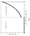
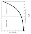
- Figures 1 to 8 illustrate embodiments of the present invention.
- Figures 3 to 8 illustrate examples of how additional distribution data for the first component of the magnetic field vector can be generated, according to embodiments of the present invention.
- top, bottom, over, under and the like in the description and the claims are used for descriptive purposes and not necessarily for describing relative positions. The terms so used are interchangeable under appropriate circumstances and the embodiments of the disclosure described herein can operate in other orientations than described or illustrated herein.
- the method comprises the steps of:
- Determining a distribution of the second and the third components preferably includes performing a Fourier transformation on the distribution data of the first component, manipulating the Fourier transformed data and performing the inverse Fourier transform.
- a Fourier transformation on the distribution data of the first component, manipulating the Fourier transformed data and performing the inverse Fourier transform.
- Equation 7 says that the B x and B y components of the magnetic field can be obtained from a two-dimensional distribution of the B z component of the magnetic field.
- Equation 7 makes use of a Cartesian coordinate system
- this result can also be applied in a cylindrical coordinate system, as is shown now.
- a cylindrical coordinate system determined by a Z-axis, with the following orthogonal directions: the radial direction 'r' is perpendicular to the Z-axis, the angular direction 'e' is perpendicular to both the Z-axis and the radial direction and indicates the rotational direction around the Z-axis, the third coordinate is the Z-direction.
- the curved cylinder surface can be transformed into a flat surface by 'developing' the cylinder.
- This cylinder surface in the cylindrical coordinate system ( R , ⁇ , Z ) is then projected onto a Cartesian coordinate system (X',Y',Z') in the following way:
- the magnetic field components in the cylindrical coordinate system can now be treated as components in a Cartesian coordinate system and Equation 7 can be applied in order to determine the B ⁇ and B z components.
- the field distribution on the cylinder is periodic in the ⁇ direction and thus is preferably subject to periodic boundary conditions in the Cartesian coordinate system when the Fourier transform is performed.
- the magnetic field components in the cylindrical coordinate system can now be treated as components in a Cartesian coordinate system and Equation 7 can be applied in order to determine the B X' and B Y' components.
- the grid in the cylindrical coordinate system may not transform to a regular grid in the Cartesian coordinate system when Equation 10 is applied.
- the transformed grid can be made regular again by interpolation methods which are well known to persons skilled in the art. From the found B X' and B Y' components the B ⁇ and B R components can be readily retrieved by performing the inverse transformation of Equation 11. Thereby, another interpolation step might be needed in order to obtain the B ⁇ and B R values at the original grid points in the cylindrical coordinate system.
- the spatial distribution of the components of a magnetic field is measured in a predetermined area, for instance a rectangular or square area, the predetermined area being flat and corresponding to the X-Y plane of the Cartesian axis system.
- Measurement of the magnetic field distribution can be performed by means of a magnetic field camera, which is based on a two-dimensional matrix of Hall-sensors, each of the Hall-sensors measuring the magnetic field locally.
- measuring the magnetic field can be performed with magneto-optical devices.
- magnetic camera devices are able to only measure an out-of-plane component of a magnetic field.
- a measured magnetic field distribution for the first component of the magnetic vector field for instance the Z-component
- Fourier analysis can advantageously be used.
- a practical application area is the field of determining the magnetic field distribution of a magnetic object, as for instance a permanent magnet.
- the method described below can be applied on a measured distribution of the Z-component of a magnetic vector field, or can be applied on an improved version thereof.
- the measured distribution of the Z-component of the magnetic field may be optimized, for instance according to a method described in European patent application EP2508906 , before the X and Y components are being determined as set out below.
- the method can be used to determine second and third component values of a magnetic vector field along any surface, for instance a flat or curved surface, the latter being for instance a cylindrical surface or a spherical surface, which may be virtual, for which the distribution of the first component is known.
- the used distribution data comprising values for the first component of a magnetic field vector may correspond to measured values, to corrected measured values, or to purely simulated values based on theoretical models, depending for instance on the context and application.
- An important condition for allowing a correct calculation of the X and Y components is that the magnetic field on the outer boundary of the measured area, the predetermined area, satisfies the correct boundary conditions. In practice this can mean that the field on the boundary is close to zero or zero (for instance below the noise level), or it could mean that there are periodic boundary conditions. If the boundary conditions are not satisfied, errors can be introduced in the calculated X and Y components. Considering the case where the magnetic field is supposed to fall off to zero at large enough distances from the magnetic source, in theory one can use a predetermined area, or measurement area, which is large enough, such that the measured first component of the magnetic field can be neglected with respect to the measurement noise at the outer boundary of the measurement area, such that these errors are not being introduced.
- magnétique camera devices have a limited measurement area, corresponding to the predetermined area, for which the first component of the magnetic vector field is being measured.
- the Z-component of the magnetic field may not be small enough or zero at its outer boundaries, which jeopardizes the possibility of determining the X and Y component within the predetermined area with a sufficient precision.
- the measured magnetic field will evolve monotonously to zero when the distance with respect to the magnetic object is increasing. If one measures in a two-dimensional area, by means of for instance the magnetic camera device comprising an active or measurement area corresponding to the predetermined area, which includes for instance a magnetic object, one can expect that the magnetic field on the outer boundary of the predetermined area will be monotonously evolving to zero, but will not have reached such a near-to-zero or zero value at these boundaries.
- the extension area can for instance be the complement area of the predetermined area, of a rectangular or square area which surrounds the predetermined area, whereby the predetermined area can for instance be positioned in the center of this rectangular or square area. It is the aim of embodiments of the present invention to simulate the expected values of the first magnetic field component in the extension area in a way that does not substantially deviate from the way the field would evolve to zero in reality. The result is a distribution of the first component of the magnetic field in a virtual larger area that does not deviate substantially from an image that would be made if it were possible to measure in the extension area directly.
- the additional distribution data of the first component of the magnetic field corresponding to the expected values for the first component of the magnetic field in the extension area is then combined with the distribution data of the first component of the magnetic field in the predetermined area, together forming a extended set of distribution data, and a Fourier transformation is applied on this extended set.
- Such a Fourier transformation the manipulation of the Fourier transformed data, which exploits inherent physical relationships between first, second and third components of the field distribution, and performing the inverse Fourier transform, results in the X and Y components of the magnetic field.
- These distributions of the X and Y components are automatically generated for not only the predetermined area, but also the extension area.
- the X and Y distribution of the magnetic vector field in the extension area is often less important, and can be removed from the data set in order to end up with X, Y and Z components of the magnetic vector field in the predetermined area only.
- the first, second and third directions do not necessarily correspond to the directions of a Cartesian coordinate system, but can equally apply to other coordinate systems, such as cylindrical or spherical coordinate systems.
- some directions have angular dimensions instead of length dimensions.
- the extended area is usually not needed, as it suffices to obtain measurement data along the full circumference of such direction, e.g. along the full circumference of a cylinder.
- the measurement data in such dimensions are inherently periodical and have periodic boundary conditions, which means that the value at 360° is equal to that at 0°. Therefore in such case the Fourier transform will be calculated in a correct way without applying the extension area in such directions.
- Similar boundary conditions can be appropriate in certain cases in Cartesian coordinates, where for example a very long magnetic object with periodic magnetization profile is measured, and for which periodic boundary conditions are applied.
- the distribution of the measured magnetic field component on the boundaries of the predetermined area is not approaching zero, because for example the magnetic object is larger than the measurement area of the magnetic field camera, it can be needed to extend the predetermined measurement area in order to make sure that the measured distribution is sufficiently approaching zero at its boundaries, so that the methods of the present invention can be applied.
- the associated method is a method for determining a magnetic field distribution of a magnet along a main surface of the magnet, the device comprising:
- the methods described in the present invention can be applied to the resulting (stitched) predetermined area.
- Another method however is to apply the so-called 'overlap-add' and 'overlap-save' methods, which are known to persons skilled in the art of signal processing, whereby the Fourier transform, data manipulation based on intrinsic physical properties of a magnetic vector field, and inverse transform are performed on each individual predetermined area comprising the larger combined predetermined area, without applying the extrapolation methods described in the current invention.
- the overlap-save or overlap-add method is applied.
- the overlap-add and overlap-save methods can also be applied in the other cases described in the present invention in the following way.
- data manipulation based on intrinsic physical properties of a magnetic vector field for instance comprising applying a Fourier transform, manipulating the Fourier transformed data, and performing an inverse Fourier Transform
- the Fourier Transfrom, data manipulations, and Inverse Fourier Transform are applied separately to the predetermined area and to (sub-regions of) the extended area in a block-wise fashion. Thereby each of the blocks can be zero padded to a certain extent in order to create overlap regions between the back-transformed blocks.
- the resulting back-transformed blocks are then combined in the final larger matrix, whereby the overlap regions are added together.
- the predetermined area can itself also be treated block-wise, for example in the case of a large magnet where the predetermined area is relatively large and is measured in a block-wise way. This method corresponds to the overlap-add method.
- a person skilled in the art will readily recognize the analogous possibility of applying the overlap-save method to the same data.
- the predetermined and extended areas can be treated block-wise or section-wise, where the determination of the second and third components is performed on each block/section separately, and the results of them added together or saved according to overlap-add and overlap-save methods, respectively.
- the overlap-add and overlap-save methods can also be used on an infinite extension area, where the extrapolation is expressed as an analytical function which the Fourier transform and other operations can be analytically determined on the interval stretching from infinity to the border of the predetermined area.
- Distribution data of the first component of the magnetic vector field in the extension area can be determined in many ways, some of which are explained below.
- Figures 3 to 8 illustrate examples of how additional distribution data for the first component of the magnetic vector field can be generated, according to embodiments of the present invention.
- the depicted patterns illustrate the evolution of the values of the first component along to a cross-section S as depicted in Fig. 1 .
- the cross-section can comprise an outer portion of the predetermined area only, but can extend up until the centre of the predetermined area.
- the Z-component or first component of the magnetic field vector is set to value zero (0) in the complete extension area.
- the method may though introduce a discontinuity in the values on the outer boundary of the predetermined area, which may still introduce errors in a subsequent calculation of the X and Y components of the magnetic field vector.
- the additional distribution data comprising the first component of the magnetic field vector is simulated or modeled for the predetermined area and the simulation results or model are/is extrapolated into the extension area.
- the magnetic field at locations lying in the extension area may be set to the same value as the nearest point in the predetermined area.
- the value of the corresponding corner of the predetermined area is set as a constant value.
- a window function is applied on the predetermined area and the extension area, which has a value "1" in the predetermined or measured area and which evolves continuously to a (near to) zero value on the outer boundary of the predetermined area.
- the window function can be a Tukey-window (illustrated in Figure 5 ) or a Planck-Taper window.
- a so-called “bump-function” or a “test-function” can be used, which have the property that they evolve from a value 1 to a value zero within a limited area, whereby they can be infinitely differentiated, and whereby they thus do not introduce discontinuities in the function or any of its first or higher order derivatives, which makes them suitable for being used as a window function in this context.
- the values of the first component of the magnetic vector field at the outer boundary of the predetermined area are evolving exponentially towards a zero value within the extension area.
- the exponential factor is predetermined such that its sufficiently small value or zero value is achieved on the outer boundary of the extension area.
- it is enough that the magnetic field distribution on the outer boundary of the extension area has a value which is below the measurement noise. This method guarantees the continuity of the values on the outer border of the predetermined area, but does not guarantee the continuity of the first derivative thereof.
- the first component of the magnetic vector field in the (boundary area of the) predetermined area is represented by a polynomial representation.
- the order of the extrapolated polynomial function can be reduced, for instance to order two ("quadratic polynomial"), or to order one ("linear polynomial"), in order not to obtain instable extrapolation values.
- This method guarantees that the continuity of the measurement values and of the derivatives is ascertained to the same extent as the order of the used polynomial function.
- the first component of the magnetic vector field in the (boundary area of the) predetermined area is represented by a rational function representation.
- the order of the extrapolated rational function can be chosen, for instance to order -1 ("1/x"), order -2 ("1/x 2 ") or order -3 ("1/x 3 "). The latter case is particularly useful since it corresponds to the decline rate of the magnetic field of a magnetic dipole, which is an approximation of a magnet at large distances from the magnet.
- This method guarantees that the magnetic field approaches zero when moving further into the extension area.
- the first component of the magnetic vector field in the (boundary area of the) predetermined area is represented by a "spline"-representation, illustrated in Figure 6 .
- the order of the extrapolated spline-function can be reduced, for instance to order two ("quadratic spline"), or to order one ("linear spline"), in order not to obtain instable extrapolation values. This method guarantees that the continuity of the measurement values and of the derivatives is ascertained to the same extent as the order of the used spline-function.
- the values of the first component of the magnetic field at the boundary of the predetermined area can be extrapolated on the basis of a simulated magnetic field distribution for the magnetic object of which the magnetic field distribution was measured.
- Simulation algorithms can be used to calculate the magnetic field distribution based for instance on one or more properties of the magnetic object such as for instance shape, material, magnetization vector, position and so forth. Also here, use can be made of any of the methods disclosed for instance in EP2508906 .
- the second and third components of the magnetic field distribution of a 'stitched' predetermined area are performed in the following way, where the 'overlap-add' or 'overlap-save' method is used.
- the Fourier transform, operations and inverse transform are performed on each individual predetermined area, which may or may not be zero padded, without applying the extrapolation methods described in the current invention.
- the overlap-save or overlap-add method is applied.
- the overlap-add or overlap-save method is used on a finite or an infinite extension area.
Landscapes
- Physics & Mathematics (AREA)
- Condensed Matter Physics & Semiconductors (AREA)
- General Physics & Mathematics (AREA)
- Measuring Magnetic Variables (AREA)
Priority Applications (9)
| Application Number | Priority Date | Filing Date | Title |
|---|---|---|---|
| PL14164069T PL2930649T3 (pl) | 2014-04-09 | 2014-04-09 | Urządzenia i sposoby wyznaczania pola magnetycznego |
| EP14164069.8A EP2930649B1 (en) | 2014-04-09 | 2014-04-09 | Devices and methods for determining a magnetic field |
| ES14164069.8T ES2597779T3 (es) | 2014-04-09 | 2014-04-09 | Dispositivos y métodos para determinar un campo magnético |
| CN201580020524.XA CN106233300B (zh) | 2014-04-09 | 2015-04-02 | 用于确定磁场的设备和方法 |
| US15/037,001 US10241159B2 (en) | 2014-04-09 | 2015-04-02 | Devices and methods for determining a magnetic field |
| KR1020167029092A KR102260905B1 (ko) | 2014-04-09 | 2015-04-02 | 자기장을 결정하는 장치 및 방법 |
| JP2016560923A JP6612772B2 (ja) | 2014-04-09 | 2015-04-02 | 磁場を決定するためのデバイスおよび方法 |
| PCT/EP2015/057299 WO2015155111A1 (en) | 2014-04-09 | 2015-04-02 | Devices and methods for determining a magnetic field |
| BR112016022975-4A BR112016022975B1 (pt) | 2014-04-09 | 2015-04-02 | Dispositivo e método para a determinação de um campo magnético em uma área pré- determinada |
Applications Claiming Priority (1)
| Application Number | Priority Date | Filing Date | Title |
|---|---|---|---|
| EP14164069.8A EP2930649B1 (en) | 2014-04-09 | 2014-04-09 | Devices and methods for determining a magnetic field |
Publications (2)
| Publication Number | Publication Date |
|---|---|
| EP2930649A1 EP2930649A1 (en) | 2015-10-14 |
| EP2930649B1 true EP2930649B1 (en) | 2016-07-13 |
Family
ID=50440595
Family Applications (1)
| Application Number | Title | Priority Date | Filing Date |
|---|---|---|---|
| EP14164069.8A Active EP2930649B1 (en) | 2014-04-09 | 2014-04-09 | Devices and methods for determining a magnetic field |
Country Status (9)
| Country | Link |
|---|---|
| US (1) | US10241159B2 (https=) |
| EP (1) | EP2930649B1 (https=) |
| JP (1) | JP6612772B2 (https=) |
| KR (1) | KR102260905B1 (https=) |
| CN (1) | CN106233300B (https=) |
| BR (1) | BR112016022975B1 (https=) |
| ES (1) | ES2597779T3 (https=) |
| PL (1) | PL2930649T3 (https=) |
| WO (1) | WO2015155111A1 (https=) |
Families Citing this family (6)
| Publication number | Priority date | Publication date | Assignee | Title |
|---|---|---|---|---|
| EP3336566B1 (en) * | 2016-12-16 | 2020-08-05 | Melexis Technologies SA | Magnetic sensor |
| US10969435B2 (en) | 2018-02-12 | 2021-04-06 | Brandon & Clark, Inc. | System and method for induction motor rotor bar surface magnetic field analysis |
| JP7209176B2 (ja) * | 2018-10-26 | 2023-01-20 | スミダコーポレーション株式会社 | 磁場発生源検出装置および磁場発生源検出方法 |
| US20200408633A1 (en) * | 2019-06-25 | 2020-12-31 | Machinesense, Llc | Systems and methods for measuring structural element deflections |
| CN112730994B (zh) * | 2020-12-22 | 2022-10-04 | 国网天津市电力公司电力科学研究院 | 基于matlab获取高压交流线路电场的方法及系统 |
| CN115795231B (zh) * | 2022-10-09 | 2023-08-04 | 中南大学 | 一种空间波数混合域三维强磁场迭代方法及系统 |
Family Cites Families (11)
| Publication number | Priority date | Publication date | Assignee | Title |
|---|---|---|---|---|
| US20040189123A1 (en) * | 2001-08-24 | 2004-09-30 | Peter Nusser | Magnetically hard object and method for adjusting the direction and position of a magnetic vector |
| EP1419510B1 (de) * | 2001-08-24 | 2010-03-24 | Berlin Heart GmbH | Hartmagnetischer gegenstand und verfahren zur einstellung von richtung und lage eines magnetvektors |
| JP2004320885A (ja) * | 2003-04-16 | 2004-11-11 | Hitachi Ltd | 回転機の磁界解析方法及びプログラム |
| US7902820B2 (en) * | 2005-05-03 | 2011-03-08 | Imec | Method and apparatus for detecting spatially varying and time-dependent magnetic fields |
| JP2008165874A (ja) * | 2006-12-27 | 2008-07-17 | Funai Electric Co Ltd | 磁界分布測定装置、温度分布測定装置、磁界分布測定方法及び温度分布測定方法 |
| JP5626678B2 (ja) * | 2010-11-24 | 2014-11-19 | 国立大学法人神戸大学 | 磁場分布取得装置 |
| PL2508906T3 (pl) * | 2011-02-14 | 2017-10-31 | Magcam Nv | Sposób oraz układ do badania układów magnetycznych |
| EP2720059B1 (en) * | 2012-10-15 | 2015-03-11 | MagCam NV | Devices and methods for determining a magnetic field distribution of a magnet along a main surface of said magnet. |
| CN103473589B (zh) * | 2013-09-10 | 2016-09-14 | 江苏多维科技有限公司 | 一种磁条形码芯片及其读取方法 |
| CN103472416B (zh) * | 2013-09-22 | 2015-07-08 | 中国工程物理研究院总体工程研究所 | 一种便携式空间磁分布测量系统 |
| ES2597780T3 (es) * | 2014-04-09 | 2017-01-23 | Magcam Nv | Dispositivos y métodos para determinar un campo magnético |
-
2014
- 2014-04-09 ES ES14164069.8T patent/ES2597779T3/es active Active
- 2014-04-09 PL PL14164069T patent/PL2930649T3/pl unknown
- 2014-04-09 EP EP14164069.8A patent/EP2930649B1/en active Active
-
2015
- 2015-04-02 US US15/037,001 patent/US10241159B2/en active Active
- 2015-04-02 BR BR112016022975-4A patent/BR112016022975B1/pt active IP Right Grant
- 2015-04-02 JP JP2016560923A patent/JP6612772B2/ja active Active
- 2015-04-02 KR KR1020167029092A patent/KR102260905B1/ko active Active
- 2015-04-02 CN CN201580020524.XA patent/CN106233300B/zh active Active
- 2015-04-02 WO PCT/EP2015/057299 patent/WO2015155111A1/en not_active Ceased
Also Published As
| Publication number | Publication date |
|---|---|
| WO2015155111A1 (en) | 2015-10-15 |
| KR20160142318A (ko) | 2016-12-12 |
| ES2597779T3 (es) | 2017-01-23 |
| US10241159B2 (en) | 2019-03-26 |
| BR112016022975A2 (https=) | 2017-08-15 |
| EP2930649A1 (en) | 2015-10-14 |
| PL2930649T3 (pl) | 2017-01-31 |
| KR102260905B1 (ko) | 2021-06-07 |
| BR112016022975B1 (pt) | 2022-08-02 |
| JP6612772B2 (ja) | 2019-11-27 |
| US20170123019A1 (en) | 2017-05-04 |
| CN106233300A (zh) | 2016-12-14 |
| CN106233300B (zh) | 2019-01-04 |
| JP2017513008A (ja) | 2017-05-25 |
Similar Documents
| Publication | Publication Date | Title |
|---|---|---|
| EP2930649B1 (en) | Devices and methods for determining a magnetic field | |
| EP2508906B1 (en) | Arrangement and method for characterizing magnetic systems | |
| EP2930650B1 (en) | Devices and methods for determining a magnetic field | |
| Xu et al. | Damage detection and assessment of broken wires in cables of a bridge based on magnetic flux leakage | |
| KR102179084B1 (ko) | 자석의 주요면을 따라 자석의 자기장 분포를 측정하는 방법 및 장치 | |
| Li et al. | Accurate 3D reconstruction of complex defects based on combined method of MFL and MFDs | |
| Ravan et al. | Sizing of multiple cracks using magnetic flux leakage measurements | |
| US11035909B2 (en) | Method of calibrating a network of magnetometers | |
| JP2016173340A (ja) | 配管検査装置 | |
| JP7473114B2 (ja) | 外場応答分布可視化装置及び外場応答分布可視化方法 | |
| Jiang et al. | Automatic detection of microcracks on the surface of special steel wire based on remanence effect | |
| Enokizono et al. | Crack size and shape determination by moving magnetic field type sensor | |
| WO2024042614A1 (ja) | 磁気粒子イメージングシステム、磁気粒子イメージング方法、および磁気粒子イメージングプログラム | |
| US10969269B1 (en) | Remote vibration sensing through opaque media using permanent magnets | |
| CN120063371A (zh) | 一种高空无人检测装备非稳态检测边界的确定方法及装置 | |
| Kovács et al. | Simulation of a developed magnetic flux leakage method | |
| CN113406186A (zh) | 基于电流偶极子的试件表面裂纹二维轮廓反演方法及装置 | |
| Prémel et al. | SIMULATION OF EDDY CURRENT INSPECTION INCLUDING MAGNETIC FIELD SENSOR SUCH AS A GIANT MAGNETO‐RESISTANCE OVER PLANAR STRATIFIED MEDIA COMPONENTS WITH EMBEDDED FLAWS | |
| Di Barba et al. | Coupling field analysis and non-deterministic optimization by means of multiprocessor parallel computation for characterizing magnetic anisotropy |
Legal Events
| Date | Code | Title | Description |
|---|---|---|---|
| PUAI | Public reference made under article 153(3) epc to a published international application that has entered the european phase |
Free format text: ORIGINAL CODE: 0009012 |
|
| AK | Designated contracting states |
Kind code of ref document: A1 Designated state(s): AL AT BE BG CH CY CZ DE DK EE ES FI FR GB GR HR HU IE IS IT LI LT LU LV MC MK MT NL NO PL PT RO RS SE SI SK SM TR |
|
| AX | Request for extension of the european patent |
Extension state: BA ME |
|
| 17P | Request for examination filed |
Effective date: 20151030 |
|
| RBV | Designated contracting states (corrected) |
Designated state(s): AL AT BE BG CH CY CZ DE DK EE ES FI FR GB GR HR HU IE IS IT LI LT LU LV MC MK MT NL NO PL PT RO RS SE SI SK SM TR |
|
| GRAP | Despatch of communication of intention to grant a patent |
Free format text: ORIGINAL CODE: EPIDOSNIGR1 |
|
| INTG | Intention to grant announced |
Effective date: 20160304 |
|
| GRAS | Grant fee paid |
Free format text: ORIGINAL CODE: EPIDOSNIGR3 |
|
| GRAA | (expected) grant |
Free format text: ORIGINAL CODE: 0009210 |
|
| AK | Designated contracting states |
Kind code of ref document: B1 Designated state(s): AL AT BE BG CH CY CZ DE DK EE ES FI FR GB GR HR HU IE IS IT LI LT LU LV MC MK MT NL NO PL PT RO RS SE SI SK SM TR |
|
| REG | Reference to a national code |
Ref country code: GB Ref legal event code: FG4D |
|
| REG | Reference to a national code |
Ref country code: AT Ref legal event code: REF Ref document number: 812843 Country of ref document: AT Kind code of ref document: T Effective date: 20160715 Ref country code: CH Ref legal event code: EP |
|
| REG | Reference to a national code |
Ref country code: IE Ref legal event code: FG4D |
|
| REG | Reference to a national code |
Ref country code: DE Ref legal event code: R096 Ref document number: 602014002614 Country of ref document: DE |
|
| REG | Reference to a national code |
Ref country code: NL Ref legal event code: FP |
|
| REG | Reference to a national code |
Ref country code: SE Ref legal event code: TRGR |
|
| REG | Reference to a national code |
Ref country code: LT Ref legal event code: MG4D |
|
| REG | Reference to a national code |
Ref country code: ES Ref legal event code: FG2A Ref document number: 2597779 Country of ref document: ES Kind code of ref document: T3 Effective date: 20170123 |
|
| PG25 | Lapsed in a contracting state [announced via postgrant information from national office to epo] |
Ref country code: FI Free format text: LAPSE BECAUSE OF FAILURE TO SUBMIT A TRANSLATION OF THE DESCRIPTION OR TO PAY THE FEE WITHIN THE PRESCRIBED TIME-LIMIT Effective date: 20160713 Ref country code: LT Free format text: LAPSE BECAUSE OF FAILURE TO SUBMIT A TRANSLATION OF THE DESCRIPTION OR TO PAY THE FEE WITHIN THE PRESCRIBED TIME-LIMIT Effective date: 20160713 Ref country code: NO Free format text: LAPSE BECAUSE OF FAILURE TO SUBMIT A TRANSLATION OF THE DESCRIPTION OR TO PAY THE FEE WITHIN THE PRESCRIBED TIME-LIMIT Effective date: 20161013 Ref country code: RS Free format text: LAPSE BECAUSE OF FAILURE TO SUBMIT A TRANSLATION OF THE DESCRIPTION OR TO PAY THE FEE WITHIN THE PRESCRIBED TIME-LIMIT Effective date: 20160713 Ref country code: IS Free format text: LAPSE BECAUSE OF FAILURE TO SUBMIT A TRANSLATION OF THE DESCRIPTION OR TO PAY THE FEE WITHIN THE PRESCRIBED TIME-LIMIT Effective date: 20161113 Ref country code: HR Free format text: LAPSE BECAUSE OF FAILURE TO SUBMIT A TRANSLATION OF THE DESCRIPTION OR TO PAY THE FEE WITHIN THE PRESCRIBED TIME-LIMIT Effective date: 20160713 |
|
| REG | Reference to a national code |
Ref country code: FR Ref legal event code: PLFP Year of fee payment: 4 |
|
| PG25 | Lapsed in a contracting state [announced via postgrant information from national office to epo] |
Ref country code: LV Free format text: LAPSE BECAUSE OF FAILURE TO SUBMIT A TRANSLATION OF THE DESCRIPTION OR TO PAY THE FEE WITHIN THE PRESCRIBED TIME-LIMIT Effective date: 20160713 Ref country code: PT Free format text: LAPSE BECAUSE OF FAILURE TO SUBMIT A TRANSLATION OF THE DESCRIPTION OR TO PAY THE FEE WITHIN THE PRESCRIBED TIME-LIMIT Effective date: 20161114 Ref country code: GR Free format text: LAPSE BECAUSE OF FAILURE TO SUBMIT A TRANSLATION OF THE DESCRIPTION OR TO PAY THE FEE WITHIN THE PRESCRIBED TIME-LIMIT Effective date: 20161014 |
|
| REG | Reference to a national code |
Ref country code: DE Ref legal event code: R097 Ref document number: 602014002614 Country of ref document: DE |
|
| PG25 | Lapsed in a contracting state [announced via postgrant information from national office to epo] |
Ref country code: RO Free format text: LAPSE BECAUSE OF FAILURE TO SUBMIT A TRANSLATION OF THE DESCRIPTION OR TO PAY THE FEE WITHIN THE PRESCRIBED TIME-LIMIT Effective date: 20160713 Ref country code: EE Free format text: LAPSE BECAUSE OF FAILURE TO SUBMIT A TRANSLATION OF THE DESCRIPTION OR TO PAY THE FEE WITHIN THE PRESCRIBED TIME-LIMIT Effective date: 20160713 |
|
| PLBE | No opposition filed within time limit |
Free format text: ORIGINAL CODE: 0009261 |
|
| STAA | Information on the status of an ep patent application or granted ep patent |
Free format text: STATUS: NO OPPOSITION FILED WITHIN TIME LIMIT |
|
| PG25 | Lapsed in a contracting state [announced via postgrant information from national office to epo] |
Ref country code: CZ Free format text: LAPSE BECAUSE OF FAILURE TO SUBMIT A TRANSLATION OF THE DESCRIPTION OR TO PAY THE FEE WITHIN THE PRESCRIBED TIME-LIMIT Effective date: 20160713 Ref country code: DK Free format text: LAPSE BECAUSE OF FAILURE TO SUBMIT A TRANSLATION OF THE DESCRIPTION OR TO PAY THE FEE WITHIN THE PRESCRIBED TIME-LIMIT Effective date: 20160713 Ref country code: SK Free format text: LAPSE BECAUSE OF FAILURE TO SUBMIT A TRANSLATION OF THE DESCRIPTION OR TO PAY THE FEE WITHIN THE PRESCRIBED TIME-LIMIT Effective date: 20160713 Ref country code: SM Free format text: LAPSE BECAUSE OF FAILURE TO SUBMIT A TRANSLATION OF THE DESCRIPTION OR TO PAY THE FEE WITHIN THE PRESCRIBED TIME-LIMIT Effective date: 20160713 Ref country code: BG Free format text: LAPSE BECAUSE OF FAILURE TO SUBMIT A TRANSLATION OF THE DESCRIPTION OR TO PAY THE FEE WITHIN THE PRESCRIBED TIME-LIMIT Effective date: 20161013 |
|
| 26N | No opposition filed |
Effective date: 20170418 |
|
| PG25 | Lapsed in a contracting state [announced via postgrant information from national office to epo] |
Ref country code: SI Free format text: LAPSE BECAUSE OF FAILURE TO SUBMIT A TRANSLATION OF THE DESCRIPTION OR TO PAY THE FEE WITHIN THE PRESCRIBED TIME-LIMIT Effective date: 20160713 |
|
| REG | Reference to a national code |
Ref country code: IE Ref legal event code: MM4A |
|
| PG25 | Lapsed in a contracting state [announced via postgrant information from national office to epo] |
Ref country code: MC Free format text: LAPSE BECAUSE OF FAILURE TO SUBMIT A TRANSLATION OF THE DESCRIPTION OR TO PAY THE FEE WITHIN THE PRESCRIBED TIME-LIMIT Effective date: 20160713 |
|
| PG25 | Lapsed in a contracting state [announced via postgrant information from national office to epo] |
Ref country code: LU Free format text: LAPSE BECAUSE OF NON-PAYMENT OF DUE FEES Effective date: 20170409 |
|
| REG | Reference to a national code |
Ref country code: FR Ref legal event code: PLFP Year of fee payment: 5 |
|
| PG25 | Lapsed in a contracting state [announced via postgrant information from national office to epo] |
Ref country code: IE Free format text: LAPSE BECAUSE OF NON-PAYMENT OF DUE FEES Effective date: 20170409 |
|
| PG25 | Lapsed in a contracting state [announced via postgrant information from national office to epo] |
Ref country code: MT Free format text: LAPSE BECAUSE OF NON-PAYMENT OF DUE FEES Effective date: 20170409 |
|
| PG25 | Lapsed in a contracting state [announced via postgrant information from national office to epo] |
Ref country code: AL Free format text: LAPSE BECAUSE OF FAILURE TO SUBMIT A TRANSLATION OF THE DESCRIPTION OR TO PAY THE FEE WITHIN THE PRESCRIBED TIME-LIMIT Effective date: 20160713 |
|
| REG | Reference to a national code |
Ref country code: AT Ref legal event code: UEP Ref document number: 812843 Country of ref document: AT Kind code of ref document: T Effective date: 20160713 |
|
| PG25 | Lapsed in a contracting state [announced via postgrant information from national office to epo] |
Ref country code: HU Free format text: LAPSE BECAUSE OF FAILURE TO SUBMIT A TRANSLATION OF THE DESCRIPTION OR TO PAY THE FEE WITHIN THE PRESCRIBED TIME-LIMIT; INVALID AB INITIO Effective date: 20140409 |
|
| PG25 | Lapsed in a contracting state [announced via postgrant information from national office to epo] |
Ref country code: CY Free format text: LAPSE BECAUSE OF FAILURE TO SUBMIT A TRANSLATION OF THE DESCRIPTION OR TO PAY THE FEE WITHIN THE PRESCRIBED TIME-LIMIT Effective date: 20160713 |
|
| PG25 | Lapsed in a contracting state [announced via postgrant information from national office to epo] |
Ref country code: MK Free format text: LAPSE BECAUSE OF FAILURE TO SUBMIT A TRANSLATION OF THE DESCRIPTION OR TO PAY THE FEE WITHIN THE PRESCRIBED TIME-LIMIT Effective date: 20160713 |
|
| P01 | Opt-out of the competence of the unified patent court (upc) registered |
Effective date: 20230515 |
|
| PGFP | Annual fee paid to national office [announced via postgrant information from national office to epo] |
Ref country code: SE Payment date: 20250311 Year of fee payment: 12 |
|
| PGFP | Annual fee paid to national office [announced via postgrant information from national office to epo] |
Ref country code: DE Payment date: 20250428 Year of fee payment: 12 |
|
| PGFP | Annual fee paid to national office [announced via postgrant information from national office to epo] |
Ref country code: GB Payment date: 20250422 Year of fee payment: 12 Ref country code: ES Payment date: 20250516 Year of fee payment: 12 |
|
| PGFP | Annual fee paid to national office [announced via postgrant information from national office to epo] |
Ref country code: IT Payment date: 20250418 Year of fee payment: 12 |
|
| PGFP | Annual fee paid to national office [announced via postgrant information from national office to epo] |
Ref country code: CH Payment date: 20250501 Year of fee payment: 12 |
|
| PGFP | Annual fee paid to national office [announced via postgrant information from national office to epo] |
Ref country code: AT Payment date: 20250422 Year of fee payment: 12 |
|
| PGFP | Annual fee paid to national office [announced via postgrant information from national office to epo] |
Ref country code: BE Payment date: 20260326 Year of fee payment: 13 |
|
| PGFP | Annual fee paid to national office [announced via postgrant information from national office to epo] |
Ref country code: NL Payment date: 20260330 Year of fee payment: 13 |
|
| PGFP | Annual fee paid to national office [announced via postgrant information from national office to epo] |
Ref country code: FR Payment date: 20260326 Year of fee payment: 13 |
|
| PGFP | Annual fee paid to national office [announced via postgrant information from national office to epo] |
Ref country code: TR Payment date: 20260326 Year of fee payment: 13 |
|
| PGFP | Annual fee paid to national office [announced via postgrant information from national office to epo] |
Ref country code: PL Payment date: 20260325 Year of fee payment: 13 |