EP2929115B1 - Dispositif de verrouillage permettant d'assembler deux pièces - Google Patents
Dispositif de verrouillage permettant d'assembler deux pièces Download PDFInfo
- Publication number
- EP2929115B1 EP2929115B1 EP13817896.7A EP13817896A EP2929115B1 EP 2929115 B1 EP2929115 B1 EP 2929115B1 EP 13817896 A EP13817896 A EP 13817896A EP 2929115 B1 EP2929115 B1 EP 2929115B1
- Authority
- EP
- European Patent Office
- Prior art keywords
- closure
- closure part
- opening
- closure device
- relative
- Prior art date
- Legal status (The legal status is an assumption and is not a legal conclusion. Google has not performed a legal analysis and makes no representation as to the accuracy of the status listed.)
- Active
Links
- 230000005291 magnetic effect Effects 0.000 claims description 35
- 238000000926 separation method Methods 0.000 claims description 33
- 230000000903 blocking effect Effects 0.000 claims description 10
- 238000013016 damping Methods 0.000 claims description 7
- 230000005540 biological transmission Effects 0.000 claims description 3
- 230000000694 effects Effects 0.000 claims description 3
- 230000002238 attenuated effect Effects 0.000 claims description 2
- 230000007246 mechanism Effects 0.000 claims description 2
- 230000001846 repelling effect Effects 0.000 claims description 2
- 230000009471 action Effects 0.000 description 2
- 230000006835 compression Effects 0.000 description 2
- 238000007906 compression Methods 0.000 description 2
- 230000007704 transition Effects 0.000 description 2
- 230000008878 coupling Effects 0.000 description 1
- 238000010168 coupling process Methods 0.000 description 1
- 238000005859 coupling reaction Methods 0.000 description 1
- 239000003302 ferromagnetic material Substances 0.000 description 1
- 230000035939 shock Effects 0.000 description 1
- 239000007787 solid Substances 0.000 description 1
Images


Classifications
-
- E—FIXED CONSTRUCTIONS
- E05—LOCKS; KEYS; WINDOW OR DOOR FITTINGS; SAFES
- E05C—BOLTS OR FASTENING DEVICES FOR WINGS, SPECIALLY FOR DOORS OR WINDOWS
- E05C19/00—Other devices specially designed for securing wings, e.g. with suction cups
- E05C19/16—Devices holding the wing by magnetic or electromagnetic attraction
-
- E—FIXED CONSTRUCTIONS
- E05—LOCKS; KEYS; WINDOW OR DOOR FITTINGS; SAFES
- E05C—BOLTS OR FASTENING DEVICES FOR WINGS, SPECIALLY FOR DOORS OR WINDOWS
- E05C19/00—Other devices specially designed for securing wings, e.g. with suction cups
- E05C19/02—Automatic catches, i.e. released by pull or pressure on the wing
-
- Y—GENERAL TAGGING OF NEW TECHNOLOGICAL DEVELOPMENTS; GENERAL TAGGING OF CROSS-SECTIONAL TECHNOLOGIES SPANNING OVER SEVERAL SECTIONS OF THE IPC; TECHNICAL SUBJECTS COVERED BY FORMER USPC CROSS-REFERENCE ART COLLECTIONS [XRACs] AND DIGESTS
- Y10—TECHNICAL SUBJECTS COVERED BY FORMER USPC
- Y10T—TECHNICAL SUBJECTS COVERED BY FORMER US CLASSIFICATION
- Y10T292/00—Closure fasteners
- Y10T292/11—Magnetic
Definitions
- the invention relates to a closure device for connecting two parts according to the preamble of claim 1.
- Such a closure device comprises a first closure part and a second closure part.
- the second closure part can be attached to the first closure part in a closing direction for closing the closure device, is held in a closed position on the first closure part, is movable to open the closure device in a direction different from the closing direction opening direction to the first closure part and can after opening the Closing device for separating the closure parts against the closing direction are removed from the first closure part.
- the opening direction is different from the closing direction, it should be understood in the present case that the opening direction points in a direction other than the closing direction and in particular is also not directed opposite to the closing direction.
- the opening direction thus has an angle different to 0 ° and 180 ° to the closing direction.
- magnetic means are provided which act between the first closure member and the second closure member to assist closure of the closure device by providing a magnetic attractive force.
- Such a closure device is for example from the WO 2008/006357 A2 known.
- opening and separating the closure parts done in the manner of a circulation movement.
- To close the closure parts are attached in a closing direction to each other.
- To open the closure parts are moved along a different direction from the closing direction, for example, directed transversely to the closing direction opening direction to each other, so that a stop between the closure parts is released.
- the closure parts can then be separated from each other by being removed from each other in the opposite direction to the closing direction.
- For re-closing the closure parts can then be set again in the closing direction together.
- the individual actuation phases are present here as “closing” (corresponding to the attachment of the second closure part to the first closure part for closing the closure device), “opening” (corresponding to the opening of the closure device by moving the second closure part in the opening direction relative to the first closure part) and “Disconnect” (corresponding to the movement of the second closure member against the closing direction relative to the first closure member for removing the closure members from each other).
- closure device In the case of such a closure device, it can happen that, after opening the closure device and after a (small) separation path of the closure parts, the closure parts are returned to one another, ie, a movement of the second closure part against the opening direction relative to the first closure part, and the closure parts are automatically pulled back into the closing position due to the magnetic means, so that the closure device immediately closes again.
- This can be uncomfortable for a user, and the closure device may possibly be difficult to operate because the closure device accidentally snaps back after opening, so that the closure device must be opened again.
- Object of the present invention is to provide a closure device available in which the opening can be done in a haptic pleasant way and in particular a snap immediately after opening is not readily possible.
- locking means are provided in the closure device, which are designed to lock a back movement of the second closure part against the opening direction relative to the first closure part during separation of the closure parts.
- the present invention is based on the idea, when separating the closure parts from one another, that a return of the closure parts to one another, ie a return movement of the second closure part against the opening direction relative to the first closure part, can not take place directly and without further ado. Due to the fact that such a provision is blocked at least in sections when the closure parts are separated from each other, the second closure part can not directly reach a position relative to the first closure part, in which the second closure part is pulled again in the closing direction towards the first closure part. By means of the blocking means, snapping-on of the closure device immediately after opening during separation of the closure parts from one another is thus prevented, so that the closure parts can be reliably removed from each other and separated from each other at least over a predetermined path.
- the magnetic attraction is at least attenuated when opening the closure device.
- the magnetic means for example a magnet on the one closure part and a magnetic anchor of a ferromagnetic material on the other closure part or a magnet on each of the one and the other closure part - cause a magnetic attraction between the closure parts when the closure parts in a to be able to close suitable location.
- the magnetic means are advantageously dimensioned so that the closure of the closure device is largely automatic, so that a user must bring the closure parts only in a suitable positional relationship to each other and the Close then under the action of the magnetic means largely automatically goes on itself.
- the magnetic means are magnetically attractive and are approximated to each other, so that the magnetic attraction force is comparatively large.
- the magnetic means on the first closure part, on the one hand, and on the second closure part, on the other hand are then separated from each other, for example sheared off by a tangential sliding or twisting movement, so that the magnetic attraction of the magnetic means is weakened.
- a reversal of the magnetic force can be effected by the magnets repelling each other after opening. While in the closed position the magnets of the closure parts facing each other in pairs with unlike poles, the same poles of the magnets are approached when opening, so that the magnets act magnetically repulsive and thus magnetically support the separation of the closure parts after opening.
- means are provided which are designed to support the separation of the closure parts after opening the closure device magnetically or spring-mechanically.
- These means may be realized by the magnetic means themselves, as previously described, by the magnetic means acting magnetically repulsive after opening and thus magnetically assisting in the separation of the closure members.
- mechanical means for example a mechanical spring, can be provided which are mechanically biased during closing and / or opening and then cause an ejection force against the closing direction for mechanically assisted separation of the closure parts from each other after opening.
- means can be provided which bring about a return of the closure parts against the opening direction to a position in which the second closure part can be attached in the closing direction to the first closure part for closing the closure device, after the second closure part for separating the closure parts over a predetermined path against the closing direction has been moved relative to the first closure member.
- the return means can be realized, for example, by the magnetic means of the closure parts themselves, which, when the second closure part is re-attached to the first closure part, bring the closure parts into a position in which closure of the closure device is possible.
- the first closure part and the second closure part are mechanically locked together in the closed position. Due to the mechanical locking, the second closure part can not be moved counter to the closing direction from the closed position relative to the first closure part. Due to the mechanical latching the two closure parts are thus held together in the closed position, so that the closure device produces a secure, reliable, heavy-duty connection between the closure parts when the force is applied against the closing direction.
- the mechanical latching can be achieved by moving the second shutter member in the opening direction relative to the first shutter member by moving the mechanically latched members toward each other in the opening direction, for example, across the closing direction, so that the second shutter member disengages from the first shutter member ,
- one of the closure parts can, for example, have a detent spring element and the other of the closure parts can have at least one latching projection.
- the detent spring element and the at least one latching projection engage with one another in a mechanically latching manner, so that movement of the second closure part against the closed position is blocked relative to the first closure part.
- To open the second closure part can then be moved or rotated to the first closure part, so that the latching projection slides out of engagement with the detent spring element and the mechanical latching is thus canceled.
- the blocking means are formed by a slide guide track for guiding the second closure part at least in sections during opening of the closure device and / or during separation of the closure parts.
- the Sliding guide track has at least one contact section, which blocks a back movement of the second closure part against the opening direction relative to the first closure part during separation of the closure parts.
- the slide guide track is arranged on one of the closure parts and is engaged, for example, with a pin or another suitable positive locking element on the other of the closure parts. As a result of the engagement, the closure parts are guided relative to one another during opening and / or during separation, wherein the pin or the form-locking element is in contact with the contact section during separation and thus prevents backward movement of the second closure part against the opening direction.
- the gate guide track has a first gate section for guiding the second shutter part relative to the first shutter part in the closing direction when closing and a second gate guide section for guiding the second shutter part relative to the first shutter part in the opening direction when opening.
- a third slide guide section may be provided, which guides the second closure part relative to the first closure part against the closing direction during separation (after opening the closure device). The sliding guide track thus indicates the movement of the second closure part relative to the first closure part during closing, opening and optionally also during separation and thus describes the circulation movement that the second closure part relative to the first closure part first when closing, then when opening and finally during separation performs.
- the blocking means may also be formed by a latching guide which, when opened, establishes a mechanical latching connection of the closure parts for blocking a return movement of the second closure part against the opening direction relative to the first closure part.
- the latching guide engages at one of the closure parts, for example, with a latching hook on the other of the closure parts into engagement, wherein the engagement is such that the second closure part can not be moved back against the opening direction.
- the latching guide provides a guide against the closing direction for separating the closure parts from one another, so that after opening the closure parts can be separated from one another in a guided manner and thus removed from one another.
- the locking guide in this case provides a guide against the closing direction over a predetermined path. After the predetermined separation, the closure parts can be moved freely back to each other and thus be placed in a position to each other in which they can be put back to each other to close the closure device.
- the second closure part is connected to an actuating element and guided on the actuating element such that for opening the closure device, the actuating element is to move in an actuating direction different from the opening direction relative to the second closure part and the movement of the actuating element in a movement of the second closure part is converted in the opening direction.
- the actuating element By means of the actuating element, the second closure part can in this case be moved in the opening direction, wherein the actuating movement of the actuating element is different from the movement of the second closure part when opening.
- the actuator for actuating in an actuating direction is different from the opening direction to move, and due to the positive guidance, the actuating movement is converted into a movement of the second closure member in the opening direction.
- the direction of actuation should be different from the opening direction, is to be understood in the present case that the actuation direction and the opening direction are not rectified to each other, so describe an angle different 0 degrees to each other.
- the actuating direction - unlike the opening direction with respect to the closing direction - may also be directed opposite to the opening direction.
- the actuation direction may be the same or opposite to the closing direction, so that the actuating element for opening the closure device is to be moved in or counter to the closing direction relative to the second closure part.
- Such an actuating element can be used in an advantageous manner, for example when using the closure device on a piece of furniture, for example on a drawer, a sliding door or a swing door use.
- the actuating element can be connected, for example, integrally with a drawer, wherein by pressure on the drawer (in the closing direction) a movement of the second closure part in the opening direction (for example, transversely to the closing direction) is effected, so that by pressing the drawer, the closure device can be solved.
- this may look like a sliding door.
- the actuating element is for example formed integrally with the sliding door, so that the second closure part is moved in the opening direction (for example, transversely to the closing direction) by moving the sliding door in the closing direction.
- the second closure part may for example be forcibly guided on the actuating element via a guide device such that upon movement of the actuating element in the actuating direction the second closure part is moved in the opening direction relative to the first closure part.
- the guide device thus the movement of the actuating element in the actuating direction is converted into a movement of the second closure member in the opening direction
- the guide means may be formed, for example, as a slanted guide with at least one oblique guideway or as a thread guide with at least one thread groove.
- An oblique guide can be used in particular when the second closure part is to be displaced linearly (in a straight line) relative to the first closure part for opening.
- a thread guide can be used, for example, when the second closure part is to be moved to open in rotation relative to the first closure part.
- a forced operation or forced coupling for example, a gearbox using gears, a cable guide using a suitable cable drive, a parallelogram or a pivoting guide using a lever mechanism.
- damping means may be provided in an advantageous development, which are designed to damp a transmission of force from the actuating element to the second closure part upon movement of the actuating element in the actuating direction.
- a power transmission is thus not directly in a rigid manner, but in a damped manner via the damping means, which may be configured, for example, that between the actuating element and the second closure member elastically resilient (damping) elements are arranged.
- the damping means By means of the damping means can be prevented, for example, that in a shock or another Force on the actuator, which is not related to a conscious operation, no unwanted opening takes place.
- the damping means may be formed, for example, as a pneumatic or hydraulic damper, which acts at pulsed load damping between the actuating element and the second closure member and blocks a pulse-like force or at least brakes. This can ensure that e.g. when used on a sliding door in a vehicle actuation of the closure device can not be done in a vehicle braking or a crash or other impulsive load.
- the second closure part is connected to an actuating element and guided on the actuating element, that for opening the closure device, the actuating element is to be moved in an actuating direction different from the opening direction relative to the second closure part and the movement of the actuating element in a movement the second closure part is converted in the opening direction.
- closure device may also comprise blocking means, which are designed to lock a retraction of the second closure part against the opening direction relative to the first closure part during separation of the closure parts.
- a closure device of the type described above can be used, in particular, on furniture elements, for example sliding door devices or drawer devices. Accordingly, a furniture element, in particular a sliding door device or a drawer device, advantageously comprise a closure device of the type described above.
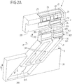
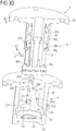
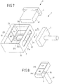
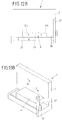
- Fig. 1 such as Fig. 2A to 2E show a first embodiment of a closure device 1, in which a first closure part 2 ("female” part) can be latchingly engaged with a second closure part 3 (“Male” part) in order, in a closed position, a mechanically strong, resilient connection between the closure parts 2, 3 produce.
- the first closure part 2 has a housing 20 and a detent spring element 21 arranged in a receiving opening 200 of the housing 20. At receiving openings 212, 213 of the detent spring element 21 magnets 22, 23 are arranged with the have different poles towards the second closure part 3.
- the detent spring element 21 also has two pairs of detent spring arms 210, 211, which are offset axially relative to one another along an opening direction Y, and which are also different in their height along a closing direction X, such as, for example Fig. 2A results.
- the second closure part 3 has a plug 311, on which two pairs of latching projections 312, 313 are arranged, which are each assigned to a pair of latching spring arms 210, 211 of the latching spring element 21.
- the pairs of latching projections 312, 313 are offset from one another along the closing direction X, corresponding to the offset in the height of the latching spring arms 210, 211, so that the pair of latching projections 312 are arranged below the pair of latching projections 313 along the closing direction X.
- the second closure part 3 is guided via a guide part 31 on a guide device 300 of an actuating element 30.
- the guide member 31 is in this case with webs 310 in the guide track 301 of the guide means 300 and is guided over the guide track 301 along an oblique direction S to the actuating element 30.
- a sliding guide track 32 is formed on the plug 311, which has a first link portion 320 and a second link portion 321 and a contact portion 322.
- the first link section 320 extends substantially along the closing direction X, while the second link section 321 extends along the opening direction Y.
- the plug 311 has two slotted guide tracks 32, which extend on both sides of the plug 311, namely on different sides of the plug 311 relative to a plane spanned by the closing direction X and the opening direction Y.
- the closure device 1 is used for releasably connecting two parts from each other.
- the closure device 1 may be part of a piece of furniture and serve for locking a sliding door, a drawer, a cabinet door or the like.
- One of the closure parts 2, 3, for example the first closure part 2 is in this case attached to a furniture body, while the other of the closure parts 2, 3, for example the second closure part 3, on the element to be adjusted, for example, the sliding door or the drawer is attached.
- the element to be adjusted for example, the drawer or the sliding door, held by the closure device 1 in a locking manner.
- the closure device 1 can then be opened, that is unlocked, to separate the closure parts 2, 3 from each other and open the element to be adjusted.
- Fig. 2A first shows the closure device 1 in a state before closing, in which the closure parts 2, 3 are present separately.
- the first closure part 2 (female part) and the actuating element 30 are in each case shown in a partial sectional view, in order to release the view into the inner receiving opening 200 of the housing 20 and the guide device 300.
- the second closure part 3 is attached to the first closure part 2 in the closing direction X (irrelevant is whether the first closure part 2 is stationary and the second closure part 3 is movable or conversely the second closure part 3 is stationary and the first closure part 2 is movable).
- the second closure part 3 is inserted into the receiving opening 200, wherein an inwardly projecting pin 24 dips into an associated gate guide track 32 of the plug 311 and first in the first gate section 320 of the slide guide track 32 passes (the receiving opening 200 has two opposing pins 24th each gate slot track 32 being associated with a pin 24, shown in FIG Fig. 2A and also in the following views 2B to 2E only one pin 24).
- two magnets 22, 23 are arranged, which are associated with two magnets 314, 315 on the plug 311.
- the magnets 22, 23 of the detent spring element 21 have different poles toward the associated magnets 314, 315 such that, for example, the magnet 22 has a north pole toward a south pole of the magnet 314 and the magnet 23 with a south pole toward a north pole of the magnet 315 points.
- the magnets 22, 23, 314, 315 magnetically attract, so that the closing of the closure device 1 magnetic supports and according to the connector 311 is pulled in the closing direction X in the receiving opening 200 of the housing 20.
- the closing is thus at least largely self-contained and thus in a haptic pleasant way for a user.
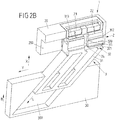
- Fig. 2B shows the closure device 1 in its closed position, in which the plug 311 is inserted into the receiving opening 200 and the pairs of latching projections 312, 313 of the plug 311 latching in engagement with the Rastfederarmen 210, 211 of the detent spring element 21.
- the pins 24 have passed through the first link section 320 of the respectively associated slide guide track 32 when closing and are now located at the break point between the first slide section 320 and the second slide section 321.
- the closure parts 2, 3 are thus latchingly connected to one another via the detent spring element 21 and the latching projections 312, 313 of the plug 31, so that the plug 311 can not be removed from the receiving opening 200 of the housing 20 against the closing direction X and the closure parts 2, 3 are thus held together in a solid, resilient manner.
- the second shutter member 3 is to be moved in the opening direction Y relative to the first shutter member 2 to disengage the latching projections 312, 313 in the opening direction Y from engagement with the associated latching spring arms 312, 313.
- the actuation of the second closure part 3 takes place here in the illustrated embodiment via the actuating element 30, on which the second closure part 3 is guided along the oblique guiding direction S.
- the second closure part 3 moves into the guide device 300 with its guide part 11 and is correspondingly moved in the opening direction Y due to the oblique guide provided by the guide device 300, so that the latching projections 312, 313 are moved relative to the detent spring arms 210, 211 and brought tangentially out of engagement therewith.
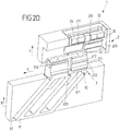
- Fig. 2C shows the closure device 1 in an open position.
- the pins 24 have been moved simultaneously in the respective associated guide slot track 32, wherein the pins 24 have each passed through the opening direction Y extending gate section 321.
- the magnets 22, 23, 314, 315 have also been displaced relative to each other along the opening direction Y at the same time.
- the magnets 23, 314 now face each other with poles of the same name, so that a magnetic repulsive force between the magnets 23, 314 counter to the closing direction X acts.
- a reset of the closure parts 2, 3 to each other, ie a return movement of the second closure member 3 against the opening direction Y in a position in which the closure parts 2, 3 again can be brought together with closing, is only possible if the second closure part 3 with his plug 311 has been moved out of the receiving opening 200 of the housing 20 of the first closure part 2 so far that the pins 24 are out of engagement with the abutment portions 322 of the plug 311 passes. This is in Fig. 2E shown.
- the plug 311 can in turn be brought into a position in which the magnets 22, 23, 314, 315 pairwise attractively facing and the pins 24 are in the gate sections 320 of the sliding guideways 32, so that the second closure part 3 turn in the closing direction X can be attached to the first closure part 2.
- This condition is the same as in Fig. 2A illustrated state.
- the biasing spring 305 may be formed, for example, as a compression spring which, when retracting the guide member 31 in the in Fig. 2C illustrated open position of the closure device 1 is stretched to pressure and for extending the second closure member 3 in the position according to Fig. 2A after opening and separation of the closure device 1 acts on the guide member 31.
- the result is a circulation movement, in which for closing the second closure part 3 in the closing direction X is attached to the first closure part 2, for opening the second closure part 3 is moved in the opening direction Y relative to the first closure part 2, for separating the second closure part 3 is moved counter to the closing direction X relative to the first closure part 2 and, for resetting, the second closure part 3 is again adjusted counter to the opening direction in its starting position.
- the actuating element 30 is also coupled to the second closure part 3 via a positive guide, there is an operation of the second closure part 3 for opening, which can be used advantageously in combination with a piece of furniture, eg a drawer or a sliding door use.
- the actuating element 30 may be formed integrally with a drawer, wherein the actuation of the closure device 1 is effected by pressure on the drawer and, accordingly, a movement of the actuating element 30 in the direction of actuation B corresponding to the closing direction X.
- the second closure member 3 By pressing the drawer (or according to the sliding door) thus the second closure member 3 can be moved in the opening direction Y, via the guide means 300 and the movement of the guide member 31 in the inclined direction S, the actuating movement of the actuating member 30 in the direction of actuation B in the Opening movement of the second closure part 3 is converted in the opening direction Y.
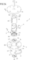
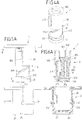
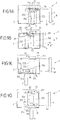
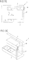
- FIG. 3A . 3B to 6A-6H Another embodiment of a closure device 1 is shown in FIG Fig. 3A . 3B to 6A-6H shown.
- Fig. 3A and Fig. 3B show here an exploded view and a partial sectional view of the closure device.
- Figs. 4A-4H, Figs. 5A-5H and 6A-6H show the closure device 1 in different views and different states, wherein Fig. 4A-4H perspective views, Fig. 5A-5H Side views and Figs. 6A-6H Sectional views along the line AA according to Fig. 5A-5H represent.
- the figures denoted by "A", "B", etc. represent the same state in each case, so that Figs. 4A, 5A and 6A a first state, 4B, 5B and 6B show a second state and so on.
- the closure device 1 has a first closure part 2 and a second closure part 3.
- the first closure part 2 comprises a housing 20, to which a semi-annular detent spring element 21 is attached in such a way that detent spring arms 210 engage through opposite recesses 201 and project into an inner receiving opening 200 of the housing 20.
- magnets 22, 23 are arranged, such as for example Fig. 2B seen.
- the second closure part 3 is guided on an actuating element 30 which is firmly connected to an actuating part 34.
- an actuating element 30 On a cylindrical lateral surface of the actuating element 30, two webs 302 are arranged, which extend axially along a closing direction X on the outside of the actuating element 30.
- a guide part 31 of the second closure part 3 is arranged and via two thread grooves 316 on threaded ridges 304 (see for example Fig. 3B ) guided.
- the guide member 31 are on both sides latching projections 312 radially outward before.
- a holding part 33 is connected to the holding openings 331, 332 magnets 314, 315 are held.
- the guide member 31 is connected to a bolt 35 in connection, which passes through a pin 340 of the actuating member 34 such that the guide member 31 along the closing direction X relative to the actuating member 34 is movable at least by a predetermined actuating travel. Due to the positive guidance provided via the thread grooves 316 and the thread ridges 304, this results in a relative movement of the guide member 31 to the actuating element 30 a Rotary movement of the guide member 31 relative to the actuator 30, as will be explained below.
- a sliding guide track 25 is arranged, which serves to guide a locking projection 312 and a web 302 and to different gate sections 250, 251, 252, 254 has.
- On the cylindrical inner wall of the receiving opening 200 are in this case (analogous to the two-sided slotted guide tracks 32 in the embodiment according to Fig. 1 and 2 ) arranged two slide guide tracks 25, which are arranged offset by 180 ° about the closing direction X on the inner wall of the receiving opening 200 and serve to guide a respective Rastvormenes 312 and web 302.
- closure device 1 The operation of the closure device 1 will be described below with reference to Figs. 4A-4H, 5A-5H and 6a-6H be explained.
- Figs. 4A, 5A and 6A the closure parts 2, 3 are separated from each other.
- the guide member 31 is hereby extended from the actuator 30, such as out Fig. 5A seen.
- the webs 302 and the latching projections 312 are aligned - as viewed along the closing direction X - in pairs with each other.
- biasing spring 305 (see Fig. 3B ), which acts between the actuator 30 and the guide member 31 and the second closure member 3 after opening and separation of the closure device 1 in the starting position according to Fig. 3A returns.
- the biasing spring 305 may be formed in this embodiment, for example, as a compression spring which is extended around the bolt 305, the bolt 305 surrounds and is arranged in a recess within the guide member 31.
- the detent spring arms 210 can deflect radially outward, so that the detent projections 312 urge the detent spring arms 210 aside and engage in detent engagement with the detent spring arms 210, as shown in FIG Figs. 4C, 5C and 6C is shown.
- the locking projections 312 engage behind the latch spring arms 210 so that the first closure part 2 and the second closure part 3 are mechanically locked together and the second closure part 3 can thus not (more) be removed from the first closure part 2 counter to the closing direction X.
- Closing is largely automatic due to the magnetic attraction between the magnets 22, 23, 314, 315.
- the magnets are 22, 23, 314, 315 in pairs opposite with opposite poles, so that the closure parts 2, 3 and magnetic held in position to each other.
- the actuating element 30 is pressed by pressing on the actuating part 34 in one of the closing directions X corresponding actuating direction B in the receiving opening 200 of the housing 20 of the first closure parts 2, as shown in Figs. 4D, 5D and 6D is shown. Due to the positive guidance between the actuating element 30 and the guide part 31 via the threaded guide realized by the thread grooves 316 and the thread legs 304, the guide part 31 is rotated in an opening direction Y (which is rotationally directed around the closing direction X), so that the latching projections 312 each move in a gate section 251 in a direction of movement V2 (see Fig. 3B ).
- the Guide member 31 is hereby rotated by a little less than 180 °, so that each locking projection 312 is moved towards the opposite sliding guide track 25 (in Fig. 3B only one slide guide track 25 is shown). If each latching projection 312 has reached the assigned slide section 252, then the latching projection 312 moves into the slide section 252 and moves in a direction of movement V3 counter to the closing direction X, also caused by the now repulsive magnets 22, 23, 314, 315, which have been rotated together with the guide member 31 are such that poles of the same name of the magnets 22, 23, 314, 315 in pairs face each other and thus repel.
- the latching projections 312 thus pass along the link sections 252 past the latching spring arms 210 of the latching spring element 21, so that the second closure part 3 can be removed from the receiving opening 200 of the housing 20 of the first closure part 2. This is in FIGS. 4E, 5E and 6E shown.
- the locking projections 312 can retract straight into the respective associated link section 252 of the opposite slide guide track 25.
- the latching projections 312 respectively come into abutment with a contact section 253 which laterally delimits the slotted section 252 and which causes the guide element 31 to not be pivoted back against the opening direction Y when the second closure part 3 is removed from the receiving opening 200.
- the abutment portions 253 of the two slide guide tracks 25 thus realize locking means for blocking a return movement of the guide member 31st
- the latching projections 312 continue to slide along the slide guide track 25 when the guide element 31 is removed, they enter the respectively assigned slide section 254 and are thus adjusted obliquely in a direction of movement V4 in the direction of the entry point 255 of the associated slide guide track 25. Because of this oblique guide, the guide member 31 is further rotated relative to the actuator 30, so that the guide member 31 is now rotated by exactly 180 ° relative to the actuator 30. In this position, the locking projections 312 and also the webs 302 emerge from the entry points 255 of the slide guide tracks 25, as shown in FIG Figs. 4F, 5F and 6F is shown.
- Locking means are also realized in this embodiment by two slide guide tracks 25, the abutment sections 253, which in the separation of the closure parts 2, 3 in front of each other (shown in FIG Fig. 4E, 5E, 6E and 4F, 5F, 6F ) Lock a return movement of the guide member 31 against the opening direction Y.
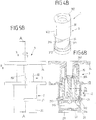
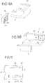
- FIG. 7, 8 and 9A to 9D illustrated another embodiment of a closure device 1 has two closure parts 2, 3, of which a second closure part 3 is at least partially enclosed by a first closure part 2 and with a handle 37 an opening 26 passes through.
- the second closure part 3 can be brought into different positions relative to the first closure part 2, but can not be completely detached from the first closure part 2.
- the second closure part 3 is located with a pin 36 (see Fig. 8 ) in a gate guide track 25 of the first closure part 2 and is guided in this way on the first closure part 2.
- the second closure part 3 is brought closer to a bottom 22 of the first closure part 2 in a closing direction X, with magnets 314, 315 of the second closure part 3 (see FIG Fig. 8 ) the magnets 22, 23 of the first closure part 2 with unlike poles face and thus a magnetic attraction during closing of the closure device 1 is effected.
- the pin 36 slides along a link portion 250 of the sliding guide track 25th
- Fig. 9A shows the closure device 1 in a closed position in which the second closure part 3 is magnetically held on the bottom of the first closure part 2 carrying the magnets 22, 23.
- an actuating element 4 can be moved in an actuating direction B in order to move the second closure part 3 in the direction of actuation B relative to the first closure part 2.
- the second closure part 3 slides with its pin 36 in a gate section 251 of the sliding guide track 25 and moves in an opening direction Y relative to the magnets 22, 23 supporting bottom of the first closure part 2, so that the same name magnets 22, 315 of the first closure part. 2 and the second closure part 3 are brought into opposing position and thus a magnetic repulsive force is effected, which causes a separation of the second closure part 3 from the bottom of the first closure part 2 supporting the magnets 22, 23 against the closing direction X.
- It runs, as in Fig. 9C shown, the pin 36 in a gate section 252, wherein the gate section 252 laterally limiting contact portion 253 prevents a return movement of the second closure member 3 against the opening direction Y.
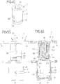
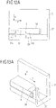
- a closure device 1 two closure parts 2, 3.
- the closure parts 2, 3 are separated from each other (see 10A, 10B and 11th ).
- Magnets 22, 23, 314, 315 are arranged on the closure parts 2, 3, which bring about a magnetic attraction force relative to one another, so that when the closure parts 2, 3 are attached to each other, a second closure part 3 automatically engages in the in Figs. 12A, 13A shown closed position is pulled.
- the magnets 22, 23, 314, 315 are magnetically attractive, so that the second closure part 3 is held on the first closure part 2.
- the second closure part 3 is moved in an opening direction Y relative to the first closure part 2 (see FIG Fig. 12B, 13B ).
- the magnets 22, 23 relative to the magnets 314, 315 tangentially shifted ("sheared off"), so that the magnetic attraction in the closed position is reversed in a repulsive force (see Fig. 12B ).
- a latching hook 38 of the second closure part 3 engages latchingly with a latching guide 27 of the first closure part 2, so that a return movement of the second closure part 3 against the opening direction Y is blocked.
- the locking guide 27 realized insofar a locking means.
- the latching guide 27 is designed such that a return movement of the second closure part 3 is locked against the opening direction Y, at the same time the closure parts 2, 3 but against the closing direction X can be separated from each other. The separation is assisted magnetically due to the repulsive force acting on separation, wherein due to the load guide 27, the closure parts 2, 3 can not immediately return to their closed position and thus the closure device 1 can not snap back immediately.
- Figs. 12C, 13C show the closure device 1 at separate closure parts 2, 3, the locking guide 27 releases the latching hook 38 after a separation movement by a distance H corresponding to the height of the latching guide 27 and the second experimental part 3 thus against the opening direction Y in the starting position according to Figs. 12D, 13D can be reset.
- This provision can be effected due to the acting magnetic forces between the magnets 22, 23, 314, 315.
- additional means for example in the form of a mechanical spring, which is tensioned when the closure device 1 is opened.
- a closure device of the type described above is advantageously used as a closure for furniture.
- the closure device can serve as a closure for furniture doors, drawers, sliding doors or the like.
- a closure device of the type described above can also be used as a closure for a bag, as a closure for a safety belt or for any other closures in which two parts securely and resiliently connected are to be and in which an opening in a lighter, haptic pleasant way should be possible to find use.
Claims (15)
- Dispositif de verrouillage (1) pour l'assemblage de deux pièces, avec- une première pièce de verrouillage (2),- une seconde pièce de verrouillage (3) qui peut être appliquée dans un sens de fermeture (X) contre la première pièce de verrouillage (2) pour fermer le dispositif de verrouillage (1), est maintenue dans une position de fermeture contre la première pièce de verrouillage (2), peut être déplacée dans un sens d'ouverture (Y) différent du sens de fermeture (X) par rapport à la première pièce de verrouillage (2) pour ouvrir le dispositif de verrouillage (1), et, après l'ouverture du dispositif de verrouillage (1), peut être éloignée de la première pièce de verrouillage (2) inversement au sens de fermeture (X) pour séparer les pièces de verrouillage (2, 3),- des moyens magnétiques (22, 23, 314, 315) qui agissent entre la première pièce de verrouillage (2) et la seconde pièce de verrouillage (3) pour soutenir la fermeture du dispositif de verrouillage (1) par la fourniture d'une force d'attraction magnétique, et- des moyens de blocage (25, 253 ; 32, 322 ; 27) qui sont formés pour, lors de la séparation des pièces de verrouillage (2, 3), bloquer un mouvement de recul de la seconde pièce de verrouillage (3) inversement au sens d'ouverture (O) par rapport à la première pièce de verrouillage (2),caractérisé en ce que les moyens de blocage sont formés par une piste de guide à coulisse (25, 32) pour guider au moins par tronçons la seconde pièce de verrouillage (3) lors de l'ouverture du dispositif de verrouillage (1) et/ou lors de la séparation des pièces de verrouillage (2, 3), dans lequel la piste de guide à coulisse (25, 32) présente au moins une section de butée (253, 322), qui, lors de la séparation des pièces de verrouillage (2, 3), bloque un mouvement de recul de la seconde pièce de verrouillage (3) inversement au sens d'ouverture (O) par rapport à la première pièce de verrouillage (2).
- Dispositif de verrouillage selon la revendication 1, caractérisé en ce que, lors de l'ouverture, la force d'attraction magnétique est au moins affaiblie.
- Dispositif de verrouillage selon la revendication 1 ou 2, caractérisé en ce que les moyens magnétiques (22, 23, 314, 315) ont une action de repoussement magnétique après le déplacement de la seconde pièce de verrouillage (3) dans le sens d'ouverture (O) par rapport à la première pièce de verrouillage (2).
- Dispositif de verrouillage selon l'une des revendications 1 à 3, caractérisé en ce que des moyens sont prévus pour soutenir de manière magnétique ou mécanique à ressort la séparation des pièces de verrouillage (2, 3) après l'ouverture du dispositif de verrouillage (1).
- Dispositif de verrouillage selon l'une des revendications précédentes, caractérisé en ce que des moyens sont prévus pour provoquer un rétablissement des pièces de verrouillage (2, 3) inversement au sens d'ouverture (O) dans une position où la seconde pièce de verrouillage (3) peut être appliquée dans le sens de fermeture (X) contre la première pièce de verrouillage (2) pour fermer le dispositif de verrouillage (1), après que la seconde pièce de verrouillage (3) a été déplacée sur un trajet prédéterminé (H) inversement au sens de fermeture (X) par rapport à la première pièce de verrouillage (2) pour séparer les pièces de verrouillage (2, 3).
- Dispositif de verrouillage selon l'une des revendications précédentes, caractérisé en ce que la première pièce de verrouillage (2) et la seconde pièce de verrouillage (3) sont encliquetées mécaniquement l'une avec l'autre dans la position de fermeture de telle sorte que la seconde pièce de verrouillage (3) n'est pas déplaçable inversement au sens de fermeture (X) hors de la position de fermeture par rapport à la première pièce de verrouillage (2).
- Dispositif de verrouillage selon l'une des revendications précédentes, caractérisé en ce que l'une des pièces de verrouillage (2, 3) présente un élément de ressort d'arrêt (21) et l'autre des pièces de verrouillage (3, 2) présente au moins une saillie d'encliquetage (312, 313), dans lequel l'élément de ressort d'arrêt (21) et l'au moins une saillie d'encliquetage (312,313) sont en prise l'un avec l'autre par encliquetage dans la position de fermeture.
- Dispositif de verrouillage selon l'une des revendications précédentes, caractérisé en ce que la piste de guide à coulisse (25, 32) présente une première section de coulisse (250, 320) pour guider la seconde pièce de verrouillage (3) par rapport à la première pièce de verrouillage (2) dans le sens de fermeture (X) lors de la fermeture et une deuxième section de guide à coulisse (251, 321) pour guider la seconde pièce de verrouillage (3) par rapport à la première pièce de verrouillage (2) dans le sens d'ouverture (O) lors de l'ouverture.
- Dispositif de verrouillage selon la revendication 8, caractérisé en ce que la piste de guide à coulisse (25, 32) présente une troisième section de coulisse (252) pour guider la seconde pièce de verrouillage (3) par rapport à la première pièce de verrouillage (2) inversement au sens de fermeture (X) lors de la séparation, après l'ouverture du dispositif de verrouillage (1).
- Dispositif de verrouillage selon l'une des revendications précédentes, caractérisé en ce que les moyens de blocage sont formés par un guide à encliquetage (27), qui, lors de l'ouverture, réalise une liaison par encliquetage mécanique des pièces de verrouillage (3) pour le blocage d'un mouvement de recul de la seconde pièce de verrouillage (3) inversement au sens d'ouverture (O) par rapport à la première pièce de verrouillage (2), dans lequel le guide à encliquetage (27) guide la seconde pièce de verrouillage (3) lors de la séparation inversement au sens de fermeture (X) par rapport à la première pièce de verrouillage (2).
- Dispositif de verrouillage selon l'une des revendications précédentes, caractérisé en ce que la seconde pièce de verrouillage (3) est reliée à un élément d'actionnement (30) et guidée au niveau de l'élément d'actionnement (30) de telle sorte que, pour ouvrir le dispositif de verrouillage (1), l'élément d'actionnement (30) doit être déplacé dans un sens d'actionnement (B) différent du sens d'ouverture (O) par rapport à la seconde pièce de verrouillage (3) et le déplacement de l'élément d'actionnement (30) est converti en un déplacement de la seconde pièce de verrouillage (3) dans le sens d'ouverture (O).
- Dispositif de verrouillage selon la revendication 11, caractérisé en ce que l'élément d'actionnement (30), pour ouvrir le dispositif de verrouillage (1), doit être déplacé dans le, ou inversement au, sens de fermeture (X) par rapport à la seconde pièce de verrouillage (3).
- Dispositif de verrouillage selon la revendication 11 ou 12, caractérisé en ce que la seconde pièce de verrouillage (3) est guidée de force au niveau de l'élément d'actionnement (30) par l'intermédiaire d'un dispositif de guidage (300) de telle sorte que, lors d'un déplacement de l'élément d'actionnement (30) dans le sens d'actionnement (B), la seconde pièce de verrouillage (3) est déplacée dans le sens d'ouverture (O) par rapport à la première pièce de verrouillage (2).
- Dispositif de verrouillage selon la revendication 13, caractérisé en ce que le dispositif de guidage (300) est formé comme guidage oblique avec au moins un rail de guidage oblique (301) ou comme guidage fileté avec au moins une gorge de filet (316).
- Dispositif de verrouillage selon l'une des revendications 11 à 14, caractérisé en ce que des moyens d'amortissement sont formés et prévus entre l'élément d'actionnement (30) et la seconde pièce de verrouillage (3), pour amortir une transmission de force de l'élément d'actionnement (30) à la seconde pièce de verrouillage (3) lors d'un déplacement de l'élément d'actionnement (30) dans le sens d'actionnement (B).
Applications Claiming Priority (2)
| Application Number | Priority Date | Filing Date | Title |
|---|---|---|---|
| DE102012222344.4A DE102012222344A1 (de) | 2012-12-05 | 2012-12-05 | Verschlussvorrichtung zum Verbinden zweier Teile |
| PCT/EP2013/075552 WO2014086874A2 (fr) | 2012-12-05 | 2013-12-04 | Dispositif de verrouillage permettant d'assembler deux pièces |
Publications (2)
| Publication Number | Publication Date |
|---|---|
| EP2929115A2 EP2929115A2 (fr) | 2015-10-14 |
| EP2929115B1 true EP2929115B1 (fr) | 2018-04-04 |
Family
ID=49918668
Family Applications (1)
| Application Number | Title | Priority Date | Filing Date |
|---|---|---|---|
| EP13817896.7A Active EP2929115B1 (fr) | 2012-12-05 | 2013-12-04 | Dispositif de verrouillage permettant d'assembler deux pièces |
Country Status (4)
| Country | Link |
|---|---|
| US (1) | US10202790B2 (fr) |
| EP (1) | EP2929115B1 (fr) |
| DE (1) | DE102012222344A1 (fr) |
| WO (1) | WO2014086874A2 (fr) |
Families Citing this family (11)
| Publication number | Priority date | Publication date | Assignee | Title |
|---|---|---|---|---|
| US9949532B2 (en) | 2015-05-15 | 2018-04-24 | Nike, Inc. | Articles of footwear with an alternate fastening system |
| US9750309B2 (en) | 2016-01-08 | 2017-09-05 | Nike, Inc. | Articles of footwear with an alternate fastening system |
| DE102015216242A1 (de) * | 2015-08-25 | 2017-03-02 | Fidlock Gmbh | Verschlussvorrichtung zum Befestigen eines Gegenstands an einem Trägerelement |
| JP6708403B2 (ja) * | 2015-12-10 | 2020-06-10 | キヤノン株式会社 | 画像形成装置 |
| DE102015225438A1 (de) * | 2015-12-16 | 2017-06-22 | Fidlock Gmbh | Verschlussvorrichtung mit einer Verstelleinrichtung zum selbsttätigen Drehen eines Verbindungselements eines Verschlussteils in eine Schließstellung |
| US10874178B2 (en) | 2017-12-07 | 2020-12-29 | Wonderland Switzerland Ag | Magnetic buckling assembly |
| KR102450616B1 (ko) * | 2019-06-06 | 2022-10-05 | 원더랜드 스위처랜드 아게 | 자기 버클 어셈블리 |
| CN112237315B (zh) | 2019-07-17 | 2023-09-29 | 明门瑞士股份有限公司 | 扣具 |
| CN117016924A (zh) | 2019-07-17 | 2023-11-10 | 明门瑞士股份有限公司 | 扣具 |
| DE102021100419A1 (de) * | 2021-01-12 | 2022-07-14 | Fidlock Gmbh | Behältnis mit einer Verschlussvorrichtung |
| CN113931543B (zh) * | 2021-09-24 | 2023-08-29 | 东莞怡合达自动化股份有限公司 | 磁力扣 |
Family Cites Families (10)
| Publication number | Priority date | Publication date | Assignee | Title |
|---|---|---|---|---|
| JPH047772Y2 (fr) * | 1986-11-11 | 1992-02-28 | ||
| GB2309252B (en) * | 1996-01-16 | 2000-10-18 | Beaver & Tapley Ltd | Latch |
| US20020149208A1 (en) * | 2001-04-16 | 2002-10-17 | Paul Zamberg | Latch mechanism |
| DE202005006516U1 (de) | 2005-04-23 | 2006-08-24 | MEPLA-WERKE LAUTENSCHLäGER GMBH & CO. KG | Zuhaltevorrichtung |
| US7775567B2 (en) * | 2005-12-13 | 2010-08-17 | Apple Inc. | Magnetic latching mechanism |
| CN101646362B (zh) * | 2006-07-12 | 2012-12-12 | 菲德洛克有限责任公司 | 机械-磁连接结构 |
| AU2007272165B2 (en) | 2006-07-12 | 2012-10-04 | Fidlock Gmbh | Mechanic-magnetic connecting structure |
| EP2061353B1 (fr) * | 2006-07-12 | 2019-08-21 | Fidlock GmbH | Fermeture magnétique |
| WO2009006888A2 (fr) | 2007-07-12 | 2009-01-15 | Fidlock Gmbh | Fermeture magnétique équipée d'un ressort d'assistance à l'ouverture |
| DE102009060119B4 (de) | 2009-12-15 | 2018-03-01 | Illinois Tool Works Inc. | Betätigungsvorrichtung |
-
2012
- 2012-12-05 DE DE102012222344.4A patent/DE102012222344A1/de not_active Withdrawn
-
2013
- 2013-12-04 US US14/649,656 patent/US10202790B2/en active Active
- 2013-12-04 EP EP13817896.7A patent/EP2929115B1/fr active Active
- 2013-12-04 WO PCT/EP2013/075552 patent/WO2014086874A2/fr active Application Filing
Also Published As
| Publication number | Publication date |
|---|---|
| EP2929115A2 (fr) | 2015-10-14 |
| US20160010371A1 (en) | 2016-01-14 |
| US10202790B2 (en) | 2019-02-12 |
| WO2014086874A3 (fr) | 2014-11-27 |
| DE102012222344A1 (de) | 2014-06-05 |
| WO2014086874A2 (fr) | 2014-06-12 |
Similar Documents
| Publication | Publication Date | Title |
|---|---|---|
| EP2929115B1 (fr) | Dispositif de verrouillage permettant d'assembler deux pièces | |
| EP2833754B1 (fr) | Dispositif de fermeture pour relier deux pièces de manière détachable | |
| EP2475278B1 (fr) | Dispositif de fermeture | |
| EP2470041B1 (fr) | Fermeture mécanique dotée d'un dispositif de verrouillage | |
| EP2475279B1 (fr) | Dispositif de fermeture | |
| EP2581531B1 (fr) | Engrenage pour une espagnolette de fenêtre, de porte ou analogue | |
| EP3167130B1 (fr) | Dispositif de fermeture à actionnement manuel avec système de temporisation | |
| WO2009103279A2 (fr) | Structure d'assemblage mécano-magnétique à sécurisation de charge | |
| WO2009127196A2 (fr) | Construction d'assemblage mécanique-magnétique | |
| WO2013075851A1 (fr) | Dispositif de fermeture | |
| DE102014005937A1 (de) | Verriegelbare Schließe | |
| EP3319483B1 (fr) | Dispositif d'entraînement destiné à un élément de meuble mobile | |
| EP4302636A2 (fr) | Dispositif de fermeture à éléments de fermeture pouvant être appliqués l'un contre l'autre | |
| WO2008128257A1 (fr) | Système de couplage pour partie de meuble mobile | |
| EP3800360A1 (fr) | Dispositif de verrouillage avec des parts de verrouillage qui s'attachent | |
| EP4026970A1 (fr) | Récipient doté d'un dispositif de fermeture | |
| DE69907311T2 (de) | Axial entkuppelndes Schloss für ein Schlossmechanismus eines Personenkraftwagens | |
| EP1954530A2 (fr) | Mecanisme d'ouverture servant a ouvrir un couvercle par deux cotes opposes | |
| DE4011722A1 (de) | Schliessvorrichtung | |
| EP2025853B1 (fr) | Dispositif d'entraîneur pour un dispositif d'entraînement de porte, un tel dispositif d'entraînement de porte et une porte | |
| EP1682737A1 (fr) | Element boitier et element de fermeture pourvu d'un dispositif de securite contre des ouvertures intempestives | |
| EP2671467A2 (fr) | Agencement de table | |
| WO2024002900A1 (fr) | Appareil de maintien pour maintenir un objet sur un ensemble | |
| WO2022100983A1 (fr) | Cache de trou de serrure | |
| EP3545151A1 (fr) | Dispositif de fermeture pour une trappe, une porte, un tiroir ou similaire |
Legal Events
| Date | Code | Title | Description |
|---|---|---|---|
| PUAI | Public reference made under article 153(3) epc to a published international application that has entered the european phase |
Free format text: ORIGINAL CODE: 0009012 |
|
| 17P | Request for examination filed |
Effective date: 20150702 |
|
| AK | Designated contracting states |
Kind code of ref document: A2 Designated state(s): AL AT BE BG CH CY CZ DE DK EE ES FI FR GB GR HR HU IE IS IT LI LT LU LV MC MK MT NL NO PL PT RO RS SE SI SK SM TR |
|
| AX | Request for extension of the european patent |
Extension state: BA ME |
|
| DAX | Request for extension of the european patent (deleted) | ||
| RAP1 | Party data changed (applicant data changed or rights of an application transferred) |
Owner name: FIDLOCK GMBH |
|
| GRAP | Despatch of communication of intention to grant a patent |
Free format text: ORIGINAL CODE: EPIDOSNIGR1 |
|
| INTG | Intention to grant announced |
Effective date: 20171024 |
|
| GRAS | Grant fee paid |
Free format text: ORIGINAL CODE: EPIDOSNIGR3 |
|
| GRAA | (expected) grant |
Free format text: ORIGINAL CODE: 0009210 |
|
| AK | Designated contracting states |
Kind code of ref document: B1 Designated state(s): AL AT BE BG CH CY CZ DE DK EE ES FI FR GB GR HR HU IE IS IT LI LT LU LV MC MK MT NL NO PL PT RO RS SE SI SK SM TR |
|
| REG | Reference to a national code |
Ref country code: GB Ref legal event code: FG4D Free format text: NOT ENGLISH |
|
| REG | Reference to a national code |
Ref country code: CH Ref legal event code: EP |
|
| REG | Reference to a national code |
Ref country code: AT Ref legal event code: REF Ref document number: 985778 Country of ref document: AT Kind code of ref document: T Effective date: 20180415 |
|
| REG | Reference to a national code |
Ref country code: IE Ref legal event code: FG4D Free format text: LANGUAGE OF EP DOCUMENT: GERMAN |
|
| REG | Reference to a national code |
Ref country code: DE Ref legal event code: R096 Ref document number: 502013009865 Country of ref document: DE |
|
| REG | Reference to a national code |
Ref country code: NL Ref legal event code: MP Effective date: 20180404 |
|
| REG | Reference to a national code |
Ref country code: LT Ref legal event code: MG4D |
|
| PG25 | Lapsed in a contracting state [announced via postgrant information from national office to epo] |
Ref country code: NL Free format text: LAPSE BECAUSE OF FAILURE TO SUBMIT A TRANSLATION OF THE DESCRIPTION OR TO PAY THE FEE WITHIN THE PRESCRIBED TIME-LIMIT Effective date: 20180404 |
|
| PG25 | Lapsed in a contracting state [announced via postgrant information from national office to epo] |
Ref country code: FI Free format text: LAPSE BECAUSE OF FAILURE TO SUBMIT A TRANSLATION OF THE DESCRIPTION OR TO PAY THE FEE WITHIN THE PRESCRIBED TIME-LIMIT Effective date: 20180404 Ref country code: NO Free format text: LAPSE BECAUSE OF FAILURE TO SUBMIT A TRANSLATION OF THE DESCRIPTION OR TO PAY THE FEE WITHIN THE PRESCRIBED TIME-LIMIT Effective date: 20180704 Ref country code: BG Free format text: LAPSE BECAUSE OF FAILURE TO SUBMIT A TRANSLATION OF THE DESCRIPTION OR TO PAY THE FEE WITHIN THE PRESCRIBED TIME-LIMIT Effective date: 20180704 Ref country code: LT Free format text: LAPSE BECAUSE OF FAILURE TO SUBMIT A TRANSLATION OF THE DESCRIPTION OR TO PAY THE FEE WITHIN THE PRESCRIBED TIME-LIMIT Effective date: 20180404 Ref country code: PL Free format text: LAPSE BECAUSE OF FAILURE TO SUBMIT A TRANSLATION OF THE DESCRIPTION OR TO PAY THE FEE WITHIN THE PRESCRIBED TIME-LIMIT Effective date: 20180404 Ref country code: SE Free format text: LAPSE BECAUSE OF FAILURE TO SUBMIT A TRANSLATION OF THE DESCRIPTION OR TO PAY THE FEE WITHIN THE PRESCRIBED TIME-LIMIT Effective date: 20180404 Ref country code: AL Free format text: LAPSE BECAUSE OF FAILURE TO SUBMIT A TRANSLATION OF THE DESCRIPTION OR TO PAY THE FEE WITHIN THE PRESCRIBED TIME-LIMIT Effective date: 20180404 Ref country code: ES Free format text: LAPSE BECAUSE OF FAILURE TO SUBMIT A TRANSLATION OF THE DESCRIPTION OR TO PAY THE FEE WITHIN THE PRESCRIBED TIME-LIMIT Effective date: 20180404 |
|
| PG25 | Lapsed in a contracting state [announced via postgrant information from national office to epo] |
Ref country code: RS Free format text: LAPSE BECAUSE OF FAILURE TO SUBMIT A TRANSLATION OF THE DESCRIPTION OR TO PAY THE FEE WITHIN THE PRESCRIBED TIME-LIMIT Effective date: 20180404 Ref country code: HR Free format text: LAPSE BECAUSE OF FAILURE TO SUBMIT A TRANSLATION OF THE DESCRIPTION OR TO PAY THE FEE WITHIN THE PRESCRIBED TIME-LIMIT Effective date: 20180404 Ref country code: GR Free format text: LAPSE BECAUSE OF FAILURE TO SUBMIT A TRANSLATION OF THE DESCRIPTION OR TO PAY THE FEE WITHIN THE PRESCRIBED TIME-LIMIT Effective date: 20180705 Ref country code: LV Free format text: LAPSE BECAUSE OF FAILURE TO SUBMIT A TRANSLATION OF THE DESCRIPTION OR TO PAY THE FEE WITHIN THE PRESCRIBED TIME-LIMIT Effective date: 20180404 |
|
| PG25 | Lapsed in a contracting state [announced via postgrant information from national office to epo] |
Ref country code: PT Free format text: LAPSE BECAUSE OF FAILURE TO SUBMIT A TRANSLATION OF THE DESCRIPTION OR TO PAY THE FEE WITHIN THE PRESCRIBED TIME-LIMIT Effective date: 20180806 |
|
| REG | Reference to a national code |
Ref country code: DE Ref legal event code: R097 Ref document number: 502013009865 Country of ref document: DE |
|
| PG25 | Lapsed in a contracting state [announced via postgrant information from national office to epo] |
Ref country code: EE Free format text: LAPSE BECAUSE OF FAILURE TO SUBMIT A TRANSLATION OF THE DESCRIPTION OR TO PAY THE FEE WITHIN THE PRESCRIBED TIME-LIMIT Effective date: 20180404 Ref country code: DK Free format text: LAPSE BECAUSE OF FAILURE TO SUBMIT A TRANSLATION OF THE DESCRIPTION OR TO PAY THE FEE WITHIN THE PRESCRIBED TIME-LIMIT Effective date: 20180404 Ref country code: CZ Free format text: LAPSE BECAUSE OF FAILURE TO SUBMIT A TRANSLATION OF THE DESCRIPTION OR TO PAY THE FEE WITHIN THE PRESCRIBED TIME-LIMIT Effective date: 20180404 Ref country code: RO Free format text: LAPSE BECAUSE OF FAILURE TO SUBMIT A TRANSLATION OF THE DESCRIPTION OR TO PAY THE FEE WITHIN THE PRESCRIBED TIME-LIMIT Effective date: 20180404 Ref country code: SK Free format text: LAPSE BECAUSE OF FAILURE TO SUBMIT A TRANSLATION OF THE DESCRIPTION OR TO PAY THE FEE WITHIN THE PRESCRIBED TIME-LIMIT Effective date: 20180404 |
|
| PLBE | No opposition filed within time limit |
Free format text: ORIGINAL CODE: 0009261 |
|
| STAA | Information on the status of an ep patent application or granted ep patent |
Free format text: STATUS: NO OPPOSITION FILED WITHIN TIME LIMIT |
|
| PG25 | Lapsed in a contracting state [announced via postgrant information from national office to epo] |
Ref country code: SM Free format text: LAPSE BECAUSE OF FAILURE TO SUBMIT A TRANSLATION OF THE DESCRIPTION OR TO PAY THE FEE WITHIN THE PRESCRIBED TIME-LIMIT Effective date: 20180404 Ref country code: IT Free format text: LAPSE BECAUSE OF FAILURE TO SUBMIT A TRANSLATION OF THE DESCRIPTION OR TO PAY THE FEE WITHIN THE PRESCRIBED TIME-LIMIT Effective date: 20180404 |
|
| 26N | No opposition filed |
Effective date: 20190107 |
|
| PG25 | Lapsed in a contracting state [announced via postgrant information from national office to epo] |
Ref country code: SI Free format text: LAPSE BECAUSE OF FAILURE TO SUBMIT A TRANSLATION OF THE DESCRIPTION OR TO PAY THE FEE WITHIN THE PRESCRIBED TIME-LIMIT Effective date: 20180404 |
|
| REG | Reference to a national code |
Ref country code: CH Ref legal event code: PL |
|
| PG25 | Lapsed in a contracting state [announced via postgrant information from national office to epo] |
Ref country code: MC Free format text: LAPSE BECAUSE OF FAILURE TO SUBMIT A TRANSLATION OF THE DESCRIPTION OR TO PAY THE FEE WITHIN THE PRESCRIBED TIME-LIMIT Effective date: 20180404 Ref country code: LU Free format text: LAPSE BECAUSE OF NON-PAYMENT OF DUE FEES Effective date: 20181204 |
|
| REG | Reference to a national code |
Ref country code: IE Ref legal event code: MM4A |
|
| REG | Reference to a national code |
Ref country code: BE Ref legal event code: MM Effective date: 20181231 |
|
| PG25 | Lapsed in a contracting state [announced via postgrant information from national office to epo] |
Ref country code: IE Free format text: LAPSE BECAUSE OF NON-PAYMENT OF DUE FEES Effective date: 20181204 |
|
| PG25 | Lapsed in a contracting state [announced via postgrant information from national office to epo] |
Ref country code: BE Free format text: LAPSE BECAUSE OF NON-PAYMENT OF DUE FEES Effective date: 20181231 |
|
| PG25 | Lapsed in a contracting state [announced via postgrant information from national office to epo] |
Ref country code: LI Free format text: LAPSE BECAUSE OF NON-PAYMENT OF DUE FEES Effective date: 20181231 Ref country code: CH Free format text: LAPSE BECAUSE OF NON-PAYMENT OF DUE FEES Effective date: 20181231 |
|
| PG25 | Lapsed in a contracting state [announced via postgrant information from national office to epo] |
Ref country code: MT Free format text: LAPSE BECAUSE OF FAILURE TO SUBMIT A TRANSLATION OF THE DESCRIPTION OR TO PAY THE FEE WITHIN THE PRESCRIBED TIME-LIMIT Effective date: 20180404 |
|
| PG25 | Lapsed in a contracting state [announced via postgrant information from national office to epo] |
Ref country code: TR Free format text: LAPSE BECAUSE OF FAILURE TO SUBMIT A TRANSLATION OF THE DESCRIPTION OR TO PAY THE FEE WITHIN THE PRESCRIBED TIME-LIMIT Effective date: 20180404 |
|
| PG25 | Lapsed in a contracting state [announced via postgrant information from national office to epo] |
Ref country code: MK Free format text: LAPSE BECAUSE OF NON-PAYMENT OF DUE FEES Effective date: 20180404 Ref country code: CY Free format text: LAPSE BECAUSE OF FAILURE TO SUBMIT A TRANSLATION OF THE DESCRIPTION OR TO PAY THE FEE WITHIN THE PRESCRIBED TIME-LIMIT Effective date: 20180404 Ref country code: HU Free format text: LAPSE BECAUSE OF FAILURE TO SUBMIT A TRANSLATION OF THE DESCRIPTION OR TO PAY THE FEE WITHIN THE PRESCRIBED TIME-LIMIT; INVALID AB INITIO Effective date: 20131204 |
|
| PG25 | Lapsed in a contracting state [announced via postgrant information from national office to epo] |
Ref country code: IS Free format text: LAPSE BECAUSE OF FAILURE TO SUBMIT A TRANSLATION OF THE DESCRIPTION OR TO PAY THE FEE WITHIN THE PRESCRIBED TIME-LIMIT Effective date: 20180804 |
|
| P01 | Opt-out of the competence of the unified patent court (upc) registered |
Effective date: 20230517 |
|
| PGFP | Annual fee paid to national office [announced via postgrant information from national office to epo] |
Ref country code: GB Payment date: 20231220 Year of fee payment: 11 |
|
| PGFP | Annual fee paid to national office [announced via postgrant information from national office to epo] |
Ref country code: FR Payment date: 20231219 Year of fee payment: 11 Ref country code: DE Payment date: 20231214 Year of fee payment: 11 Ref country code: AT Payment date: 20231214 Year of fee payment: 11 |