EP2470041B1 - Fermeture mécanique dotée d'un dispositif de verrouillage - Google Patents
Fermeture mécanique dotée d'un dispositif de verrouillage Download PDFInfo
- Publication number
- EP2470041B1 EP2470041B1 EP10757402.2A EP10757402A EP2470041B1 EP 2470041 B1 EP2470041 B1 EP 2470041B1 EP 10757402 A EP10757402 A EP 10757402A EP 2470041 B1 EP2470041 B1 EP 2470041B1
- Authority
- EP
- European Patent Office
- Prior art keywords
- connecting module
- connection module
- locking
- module
- closure device
- Prior art date
- Legal status (The legal status is an assumption and is not a legal conclusion. Google has not performed a legal analysis and makes no representation as to the accuracy of the status listed.)
- Active
Links
- 230000005291 magnetic effect Effects 0.000 claims description 70
- 230000000903 blocking effect Effects 0.000 claims description 6
- 238000006073 displacement reaction Methods 0.000 description 20
- 238000000034 method Methods 0.000 description 9
- 210000001331 nose Anatomy 0.000 description 8
- 230000005484 gravity Effects 0.000 description 6
- 238000003780 insertion Methods 0.000 description 6
- 230000037431 insertion Effects 0.000 description 6
- ORQBXQOJMQIAOY-UHFFFAOYSA-N nobelium Chemical compound [No] ORQBXQOJMQIAOY-UHFFFAOYSA-N 0.000 description 6
- BGPVFRJUHWVFKM-UHFFFAOYSA-N N1=C2C=CC=CC2=[N+]([O-])C1(CC1)CCC21N=C1C=CC=CC1=[N+]2[O-] Chemical compound N1=C2C=CC=CC2=[N+]([O-])C1(CC1)CCC21N=C1C=CC=CC1=[N+]2[O-] BGPVFRJUHWVFKM-UHFFFAOYSA-N 0.000 description 5
- 230000000694 effects Effects 0.000 description 5
- 238000012546 transfer Methods 0.000 description 5
- 238000003825 pressing Methods 0.000 description 4
- 238000013461 design Methods 0.000 description 3
- 238000004519 manufacturing process Methods 0.000 description 3
- 238000009416 shuttering Methods 0.000 description 3
- XEEYBQQBJWHFJM-UHFFFAOYSA-N Iron Chemical compound [Fe] XEEYBQQBJWHFJM-UHFFFAOYSA-N 0.000 description 2
- 238000013459 approach Methods 0.000 description 2
- 230000005294 ferromagnetic effect Effects 0.000 description 2
- 229910000831 Steel Inorganic materials 0.000 description 1
- 238000004026 adhesive bonding Methods 0.000 description 1
- 230000015572 biosynthetic process Effects 0.000 description 1
- 230000000052 comparative effect Effects 0.000 description 1
- 230000000881 depressing effect Effects 0.000 description 1
- 230000000994 depressogenic effect Effects 0.000 description 1
- 238000011065 in-situ storage Methods 0.000 description 1
- 238000009434 installation Methods 0.000 description 1
- 229910052742 iron Inorganic materials 0.000 description 1
- CNQCVBJFEGMYDW-UHFFFAOYSA-N lawrencium atom Chemical compound [Lr] CNQCVBJFEGMYDW-UHFFFAOYSA-N 0.000 description 1
- 239000002184 metal Substances 0.000 description 1
- 229910052751 metal Inorganic materials 0.000 description 1
- 230000005405 multipole Effects 0.000 description 1
- 238000009958 sewing Methods 0.000 description 1
- 238000010008 shearing Methods 0.000 description 1
- 239000010959 steel Substances 0.000 description 1
- 238000003860 storage Methods 0.000 description 1
Images


Classifications
-
- E—FIXED CONSTRUCTIONS
- E05—LOCKS; KEYS; WINDOW OR DOOR FITTINGS; SAFES
- E05B—LOCKS; ACCESSORIES THEREFOR; HANDCUFFS
- E05B65/00—Locks or fastenings for special use
- E05B65/52—Other locks for chests, boxes, trunks, baskets, travelling bags, or the like
-
- A—HUMAN NECESSITIES
- A44—HABERDASHERY; JEWELLERY
- A44B—BUTTONS, PINS, BUCKLES, SLIDE FASTENERS, OR THE LIKE
- A44B11/00—Buckles; Similar fasteners for interconnecting straps or the like, e.g. for safety belts
- A44B11/25—Buckles; Similar fasteners for interconnecting straps or the like, e.g. for safety belts with two or more separable parts
- A44B11/258—Buckles; Similar fasteners for interconnecting straps or the like, e.g. for safety belts with two or more separable parts fastening by superposing one part on top of the other
-
- A—HUMAN NECESSITIES
- A44—HABERDASHERY; JEWELLERY
- A44B—BUTTONS, PINS, BUCKLES, SLIDE FASTENERS, OR THE LIKE
- A44B11/00—Buckles; Similar fasteners for interconnecting straps or the like, e.g. for safety belts
- A44B11/25—Buckles; Similar fasteners for interconnecting straps or the like, e.g. for safety belts with two or more separable parts
- A44B11/2592—Buckles; Similar fasteners for interconnecting straps or the like, e.g. for safety belts with two or more separable parts fastening by sliding in the main plane or a plane parallel to the main plane of the buckle
-
- A—HUMAN NECESSITIES
- A45—HAND OR TRAVELLING ARTICLES
- A45C—PURSES; LUGGAGE; HAND CARRIED BAGS
- A45C13/00—Details; Accessories
- A45C13/10—Arrangement of fasteners
- A45C13/1069—Arrangement of fasteners magnetic
-
- A—HUMAN NECESSITIES
- A45—HAND OR TRAVELLING ARTICLES
- A45C—PURSES; LUGGAGE; HAND CARRIED BAGS
- A45C13/00—Details; Accessories
- A45C13/10—Arrangement of fasteners
- A45C13/1076—Arrangement of fasteners with a snap action
- A45C13/1084—Arrangement of fasteners with a snap action of the latch-and-catch type
-
- A—HUMAN NECESSITIES
- A45—HAND OR TRAVELLING ARTICLES
- A45C—PURSES; LUGGAGE; HAND CARRIED BAGS
- A45C13/00—Details; Accessories
- A45C13/10—Arrangement of fasteners
- A45C13/12—Arrangement of fasteners of press-button or turn-button fasteners
- A45C13/123—Arrangement of fasteners of press-button or turn-button fasteners of press-buttons
-
- A—HUMAN NECESSITIES
- A45—HAND OR TRAVELLING ARTICLES
- A45C—PURSES; LUGGAGE; HAND CARRIED BAGS
- A45C13/00—Details; Accessories
- A45C13/10—Arrangement of fasteners
- A45C13/12—Arrangement of fasteners of press-button or turn-button fasteners
- A45C13/126—Arrangement of fasteners of press-button or turn-button fasteners of turn-buttons
-
- E—FIXED CONSTRUCTIONS
- E05—LOCKS; KEYS; WINDOW OR DOOR FITTINGS; SAFES
- E05B—LOCKS; ACCESSORIES THEREFOR; HANDCUFFS
- E05B13/00—Devices preventing the key or the handle or both from being used
- E05B13/10—Devices preventing the key or the handle or both from being used formed by a lock arranged in the handle
- E05B13/103—Combination lock
-
- E—FIXED CONSTRUCTIONS
- E05—LOCKS; KEYS; WINDOW OR DOOR FITTINGS; SAFES
- E05B—LOCKS; ACCESSORIES THEREFOR; HANDCUFFS
- E05B37/00—Permutation or combination locks; Puzzle locks
- E05B37/12—Permutation or combination locks; Puzzle locks with tumbler discs on several axes
-
- E—FIXED CONSTRUCTIONS
- E05—LOCKS; KEYS; WINDOW OR DOOR FITTINGS; SAFES
- E05B—LOCKS; ACCESSORIES THEREFOR; HANDCUFFS
- E05B37/00—Permutation or combination locks; Puzzle locks
- E05B37/16—Permutation or combination locks; Puzzle locks with two or more push or pull knobs, slides, or the like
-
- E—FIXED CONSTRUCTIONS
- E05—LOCKS; KEYS; WINDOW OR DOOR FITTINGS; SAFES
- E05B—LOCKS; ACCESSORIES THEREFOR; HANDCUFFS
- E05B47/00—Operating or controlling locks or other fastening devices by electric or magnetic means
- E05B47/0038—Operating or controlling locks or other fastening devices by electric or magnetic means using permanent magnets
- E05B47/004—Operating or controlling locks or other fastening devices by electric or magnetic means using permanent magnets the magnets acting directly on the bolt
-
- A—HUMAN NECESSITIES
- A44—HABERDASHERY; JEWELLERY
- A44D—INDEXING SCHEME RELATING TO BUTTONS, PINS, BUCKLES OR SLIDE FASTENERS, AND TO JEWELLERY, BRACELETS OR OTHER PERSONAL ADORNMENTS
- A44D2203/00—Fastening by use of magnets
-
- Y—GENERAL TAGGING OF NEW TECHNOLOGICAL DEVELOPMENTS; GENERAL TAGGING OF CROSS-SECTIONAL TECHNOLOGIES SPANNING OVER SEVERAL SECTIONS OF THE IPC; TECHNICAL SUBJECTS COVERED BY FORMER USPC CROSS-REFERENCE ART COLLECTIONS [XRACs] AND DIGESTS
- Y10—TECHNICAL SUBJECTS COVERED BY FORMER USPC
- Y10T—TECHNICAL SUBJECTS COVERED BY FORMER US CLASSIFICATION
- Y10T292/00—Closure fasteners
- Y10T292/08—Bolts
- Y10T292/096—Sliding
- Y10T292/0969—Spring projected
-
- Y—GENERAL TAGGING OF NEW TECHNOLOGICAL DEVELOPMENTS; GENERAL TAGGING OF CROSS-SECTIONAL TECHNOLOGIES SPANNING OVER SEVERAL SECTIONS OF THE IPC; TECHNICAL SUBJECTS COVERED BY FORMER USPC CROSS-REFERENCE ART COLLECTIONS [XRACs] AND DIGESTS
- Y10—TECHNICAL SUBJECTS COVERED BY FORMER USPC
- Y10T—TECHNICAL SUBJECTS COVERED BY FORMER US CLASSIFICATION
- Y10T70/00—Locks
- Y10T70/70—Operating mechanism
- Y10T70/7153—Combination
- Y10T70/735—Operating elements
- Y10T70/7407—Operating indicators
-
- Y—GENERAL TAGGING OF NEW TECHNOLOGICAL DEVELOPMENTS; GENERAL TAGGING OF CROSS-SECTIONAL TECHNOLOGIES SPANNING OVER SEVERAL SECTIONS OF THE IPC; TECHNICAL SUBJECTS COVERED BY FORMER USPC CROSS-REFERENCE ART COLLECTIONS [XRACs] AND DIGESTS
- Y10—TECHNICAL SUBJECTS COVERED BY FORMER USPC
- Y10T—TECHNICAL SUBJECTS COVERED BY FORMER US CLASSIFICATION
- Y10T70/00—Locks
- Y10T70/70—Operating mechanism
- Y10T70/7441—Key
- Y10T70/7486—Single key
Definitions
- the invention relates to a closure device according to the preamble of claim 1.
- Such a closure device has a first connection module and a second connection module, of which the first connection module can be arranged in a closing direction on the second connection module and then mechanically locked in a closed position with the second connection module.
- the shutter may be opened by releasing the first connection module by moving the first connection module or an operating member of the first connection module in an opening direction different from the closing direction by releasing the latch from the second connection module.
- a first connection module and a second connection module each have one or more magnets which act in such an attractive manner between the first connection module and the second connection module that the first connection module engages in latching fashion with the second connection module.
- the closure of the closure takes place in a closing direction, which is directed substantially perpendicular to the extension planes of the first connection module and the second connection module.
- the latching elements of the first connection module and of the second connection module are disengaged, wherein the movement is simultaneously accompanied by the magnetic Attraction between the first connection module and the second connection module - due to a movement of the magnets relative to each other - is weakened, so that the first connection module can be detached from the second connection module.
- magnets are provided to support the closing movement, the effect of which weakens when opening, both the closing process and the opening process can be done in a lighter and haptic pleasant way.
- a first connection module and a second connection module can be brought together with magnetic support latching engagement, the release of the latch by a displacement or Verwarterrorism the first connection module or a portion of the first connection module relative to the second connection module, wherein the displacement or rotational movement of a latching element of a connection module runs onto a slope of the other connection module and is thereby pressed out of engagement with an associated latching element of the other connection module, so that the latching of the first connection module and the second connection module is canceled.
- the locking devices of WO 2008/006 357 A2 and the WO 2009/01 00 49 A2 is common that the latching locking of the first connection module with the second connection module in the closed position by a movement of the first connection module or a part of the first connection module (in the form of an actuating element) relative to the second connection module in an opening direction, extending from the closing direction for manufacturing the lock differs, is solvable.
- a first connection module or an actuator provided thereon By appropriately operating a first connection module or an actuator provided thereon by moving it in the opening direction, the first connection module is detached from the second connection module.
- the release of the lock can thus be carried out by suitable operation of the first connection module or the part of the first connection module (in the form of an actuating element) substantially unhindered and free.
- connection modules are mechanically locked together in a closed position, so that the connection modules can not be separated against a closing direction from each other.
- connection modules can easily do so be solved from each other that the connection module is moved in an opening direction relative to the connection module, in order to solve the mechanical locking in this way.
- the US 2009/031541 A1 discloses a buckle for securing a seat belt after being wrapped around a vehicle occupant.
- the buckle closing is carried out in that a tongue is inserted into a plug-in buckle, whereby by inserting a locking element engages with an opening of the tongue and thus fixes the tongue to train loaded in the buckle.
- a release of the closure device can only take place, if this is also intended.
- Object of the present invention is to provide a closure device of the type mentioned, which is secured in a simple and easy to use against accidental release.
- a locking device for preventing movement of the first connection module or the part of the first connection module in the opening direction, when the first connection module and the second connection module are in the closed position, is provided, wherein the Verrieglungsvorraum for moving the first connection module or the part of the first connection module in the opening direction can be unlocked.
- the idea of the present invention is to provide a locking device which prevents inadvertent movement of the first connection module or of the part of the first connection module for releasing the closure device.
- the locking device holds the first connection module or the part of the first connection module to be actuated for releasing the closure device, so that it can not be moved in the opening direction and thus the closure device can not be opened.
- the locking device is designed so that it can be unlocked and with unlocked locking device, a movement of the first connection module or the part of the first connection module in the opening direction is possible, so that the latching of the first connection module with the second connection module repealed and the first connection module can be solved by the second connection module.
- the locking device is a safety measure that prevents inadvertent release of the closure device. In this way, the closure device securely holds the first connection module and the second connection module together and also ensures a secure connection during operation and under load.
- the opening direction differs from the closing direction, it should be understood in the present case that the opening direction points in a direction other than the closing direction and is not directed parallel thereto. In particular, the opening direction is thus not directed against the closing direction.
- the movement of the first connection module or of the part of the first connection module to be actuated to open the closure device may in particular be a displacement movement transverse to the closing direction, a rotational movement in a plane transverse to the closing direction or a pivoting movement about an axis of rotation transverse to the closing direction.
- the opening direction (which can also be a direction of rotation) differs from the closing direction, so that the connection of the first connection module with the second connection module for closing the closure device in the closing direction, the opening, however, by a movement in one of the closing direction is different, for example, transverse to the closing direction opening direction is effected.
- At least one spring locking element d. H. a spring-mounted locking element, provided, which engages in at least one locking piece on the other connecting module to form a Federverrastung.
- the spring locking element may for example be a resilient latching element in the manner of a clip.
- the locking piece may be, for example, a latching nose on which the spring locking element engages positively.
- magnetic means are provided, which cause a magnetic attraction between the first connection module and the second connection module to support the transfer of the first connection module in the closed position.
- the closure device can be closed in a light and haptic pleasant manner by magnetically assisting the closing process when the first connection module is attached to the second connection module and the mechanical locking is automatically produced.
- the Federverrastung can be locked by arranging the first connection module in the closing direction of the second connection module, in which case the at least one spring locking element engages the at least one locking piece positively.
- the first connection module and the second connection module are attracted by the magnetic means, so that the spring lock can advantageously engage largely automatically.
- the closure device is released by moving the first connection module or the part of the first connection module to be actuated relative to the second connection module in such a way that the at least one spring locking element and the at least one locking element of the spring latch are disengaged.
- the at least one spring locking element and the at least one locking piece of the spring latching can be displaced relative to one another such that the at least one spring locking element comes out of the region of the at least one locking piece along the opening direction, so that the latching is released.
- the idea here is that the spring locking element is displaced so far in the opening direction relative to the locking piece until it passes out of the region of the locking piece and is thus no longer held by the locking piece form fit. In this shifted position, the locking is canceled.
- the displacement of the spring locking element relative to the locking piece can be done by a tangential, linear movement or a rotational movement of the first connection module or the part to be actuated of the first connection module relative to the second connection module.
- the at least one spring locking element is displaced relative to the at least one locking piece such that the at least one spring locking element is pressed out of engagement with the at least one locking piece by running on a ramp inclined transversely to the opening direction.
- the spring locking element runs on a slope which acts on the spring locking element, that this is pressed transversely to the opening direction out of engagement with the at least one locking piece, so that the positive engagement of the spring locking element with the Locking piece is lifted.
- this can be done by a linear displacement movement or a rotational movement of the first connection module or the part to be actuated of the first connection module relative to the second connection module.
- the at least one spring locking element and the at least one locking piece of the spring lock are designed in the manner of a thread, see above in that by rotating the first connection module or the part of the first connection module to be actuated relative to the second connection module, the at least one spring locking element and the at least one locking piece can be screwed out of engagement.
- the spring locking element and the locking piece each have at least one thread groove, which can be brought into latching engagement with one another in the closing direction in a spring-elastic manner. Characterized in that the spring locking element and the locking piece are then screwed apart, the spring locking element can be brought out of engagement with the locking piece, so that the latch is released and the first connection module can be removed from the second connection module.
- the optionally used magnetic means are designed such that the movement of the first closure part or the part to be actuated of the first closure part in the opening direction simultaneously also the magnetic means are moved to each other such that the magnetic attraction between the first connection module and the second connection module is weakened.
- at least one magnet or on the one hand at least one magnet and on the other hand at least one magnetic, for example ferromagnetic armature (for example in the form of a steel or iron sheet) can be arranged on the first connecting module and on the second connecting module.
- the at least one magnet or the magnetic armature of the first connection module and the at least one magnet or the magnetic armature of the second connection module are then moved relative to one another such that the magnetic attraction weakens.
- a magnet is provided on the first connection module and on the second connection module, then they are facing each other frontally with different poles for closing the closure device, so that they attract each other and establish the latching of the first connection module with the second connection module.
- the magnets can be moved tangentially to each other so that they are no longer face to face and the attraction between them is weakened.
- connection module If two or more magnets are used at each connection module, it is also conceivable that the movement of the first connection module or the part to be actuated of the first connection module of the same poles of the magnets are approximated, so that, if necessary, reverse the magnetic attraction even in a magnetic repulsive force can thereby also magnetically assist the opening of the closure device.
- restoring means are furthermore provided for transferring the first connection module or the part of the first connection module to be actuated into a position in which the first connection module can be latched to the second connection module.
- the restoring means for example, formed by a mechanical spring, cause that when attaching the first connection module to the second connection module they are aligned in such a manner as to each other that - with the support of the magnetic means - the locking can be made.
- the return means by the action of the return means, the first connection module or the part of the first connection module to be actuated are returned from the position moved to open in the opening direction, so that the closure device is easily closed again by attaching the first connection module to the second connection module can.
- these return means can also be realized by the magnetic means, so that additional means, for example in the form of a mechanical spring are not required.
- the magnetic means cause by the force acting between their magnetic elements attraction that the first connection module or its intended for locking parts automatically reach their required position for locking.
- the locking device may, for example, comprise at least one locking element movably arranged on the first connection module or on a part of the first connection module for engagement in a recess on the second connection module or on a second part of the first connection module such that movement of the first connection module or of the one to be actuated Part of the first connection module is prevented in the opening direction for releasing the first connection module from the second connection module.
- the locking element can be designed, for example, as a locking bolt, which connects the first connecting module to the second connecting module in a locking manner that the first connection module can not be moved relative to the second connection module and thus an opening of the closure device is excluded.
- the locking element may connect a part of the first connection module to be opened for opening the locking device to a stationary part of the first connection module such that the part to be actuated does not move in the opening direction, for example can not be twisted or displaced. It is essential here that the locking element prevents movement of the part to be actuated of the first connection module for opening the closure device, so that opening of the closure device is only possible when the locking element is unlocked, that is no longer engaged in the associated recess.
- a plurality of locking elements may be provided which are to be operated to open the closure device in an unlocking manner.
- the locking device is designed for actuation by means of a key or a numerical code.
- the unlocking of the locking device then takes place only by using a key or by entering a numerical code, so that the locking device also provides a theft protection available, in the context of whose unauthorized persons opening the closure device is not possible.
- the locking device is designed to automatically reach its locked position when arranging the first connection module on the second connection module, so that in the closed position the first connection module automatically locks with the second connection module and at the same time the closure device is locked, that an opening of the closure device is possible only by unlocking the locking device.
- the locking elements of the locking device can be biased by mechanical springs, for example, so that when the locking state is established, the locking elements automatically engage with the associated recesses in a locking manner.
- the locking device by a movement of the first Connection module or a part of the first connection module can be unlocked in a unlocking.
- the unlocking direction differs from the opening direction and is not directed parallel to this.
- the unlocking direction can be directed transversely to the opening direction or, if the movement in the opening direction is configured as a linear movement, be configured as a direction of rotation.
- Possible - but not mandatory - is also that the unlocking direction differs both from the opening direction and from the closing direction and is not directed parallel to one of these.
- the unlocking of the closure device is thus carried out not by actuation of a separate locking element, but by a movement of the first connection module or a part of the first connection module, so that the locking device can be formed integrally with the first connection module or a part of the first connection module.
- the idea here is to create a further degree of freedom for the mobility of the first connection module or a part of the first connection module for the unlocking movement.
- the first connection module can be attached in the closing direction to the second connection module can be solved by movement in the direction different from the closing direction, for example, directed transversely to the closing direction opening direction of the second connection module, but must do so by a movement in the at least from the opening direction different unlocking previously unlocked.
- the locking device may be formed by a locking element fixedly arranged on the first or second connection module, which engages in a locked, closed state of the closure device in a groove on the other of the first and second connection module.
- the opening direction can be directed, for example, transversely to the closing direction and the unlocking direction can be designed as a direction of rotation about the closing direction, wherein the locking element can be disengaged from the groove by turning the first connecting module or a part of the first connecting module in the unlocking direction Move connecting module or the part of the first connection module in the opening direction relative to the second connection module and to open the closure device can.
- return means may be provided which cause the first connection module or the part of the first connection module in the attachment to the second connection module in a position in which it locks with the second connection module and at the same time the locking device is locked.
- This provision may be realized, for example, by additional spring means biasing the first connection module or the first connection module into a locked position or by the magnetic means causing the first connection module or the part of the first connection module to attach to the second connection module, for example is rotated so that the locking device is automatically locked.
- the magnetic means may be formed by two identical non-rotationally symmetric - for example rectangular - magnets facing each other with unlike poles and thereby attract each other and try to take a position in which both magnets are congruent.
- rectangular magnets for example, consist of two rotated by 180 ° to each other positions in which the magnets face congruent attractive. These two positions then correspond to positions of the first (or the part of the first) connection module and the second connection module to each other, in which the first and second connection module can be locked together.
- the magnetic means may also be polarized so that magnets on the first connection module and magnets on the second connection module are multi-pole and automatically align when attaching the connection modules together in a preferred position in which a lock can be made.
- the first connection module or a part of the first connection module for opening the closure device relative to the second connection module can be pivoted in the opening direction about a rotational axis directed transversely to the closing direction.
- the locking device in the locked state prevents a pivoting movement of the first connection module or a part of the first connection module, wherein the locking device, for example, by a arranged on one of the first and second connection module locking element and on the other of the first and second connection module, in locked state is formed with the locking element engaged engagement element and the locking device by moving the first connection module or a part of the first connection module can be unlocked in a different unlocking direction from the opening direction.
- the first connection module is attached in a closing direction to the second connection module and can be released from the second connection module by moving at least a part of the first connection module in a direction of the opening direction corresponding pivoting direction.
- the unlocking direction can be directed in this case, for example, transversely or opposite to the closing direction and thus differs from the opening direction.
- return means can be realized by additional spring means or by the already provided magnetic means, which cause the first connection module or the part of the first connection module when closing the closure device automatically comes to a position in which it when locking the connection modules together in its locked Condition passes and can be opened only by movement in the unlocking direction and subsequent movement in the opening direction.
- the opening operation is divided into two components of movement of the first connection module or a part of the first connection module.
- the first connection module or a part of the first connection module must be moved by a predetermined distance in the unlocking direction, in order to release the locking device in this way.
- the first connection module or the part of the first connection module is then moved in the opening direction, so that the mechanical locking between the first connection module and the second connection module can be canceled and the connection modules can thus be separated from one another.
- the result is a haptic pleasant opening process, which simultaneously ensures a secure hold in the closed position of the closure device and thus a secure connection of components to be joined.
- closure device The advantage of this closure device is that the opening can not be done unintentionally, since two operations are necessary: unlocking and lateral sliding or twisting. On the other hand, the closure device closes in a very pleasant way, since the magnet closes the detent automatically. After locking, the lock is then locked manually.
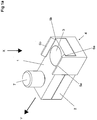
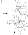
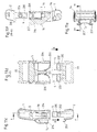
- Fig. 1a to 1e show a first embodiment of a closure device with a first connection module 1 and a second connection module 2.
- the closure device can be used for example as a closure for a bag, a backpack, a suitcase or other container or as a rope or Gurtanitati or anywhere, where two elements are to be loaded and releasably connected to each other.
- Fig. 1 a shows the closure device in a closed position, in which the first connection module 1 and the second connection module 2 are mechanically locked together by means arranged on the second connection module 2 spring locking elements 5a, 5b serving as locking pieces 6a, 6b edges of the first connection module 1 in a form-fitting engagement stand, so that the connection of the first connection module 1 and the second connection module 2 is mechanically secured against a load acting opposite to a closing direction X.
- connection module 1 and at the second connection module 2 for the realization of magnetic means in the manner of a magnet-armature system each have a magnet 3, 4 (or on the one hand a magnet and on the other hand a magnetic armature) arranged in the in Fig. 1a shown closed position with opposite poles face frontally and magnetically attract.
- the magnetic means 3, 4 serve to assist the closing process and to effect the production of the mechanical latching as far as possible automatically, so that the closure device can be closed in a light and haptic manner that is pleasant for a user.
- Closure device shown in the closed position can be opened by the first connection module 1 is moved in a direction transverse to the closing direction opening direction Y relative to the second connection module 2.
- the edges of the first connection module 1 serving as locking pieces 6a, 6b slide out of engagement with the spring locking elements 5a, 5b (see FIG Fig. 1c) , so that the first connection module 1 can be removed from the second connection module 2 (see Fig. 1d) ,
- a locking device which prevents a lateral opening movement in the opening direction Y between the spring locking elements 5a, 5b and the locking pieces 6a, 6b.
- the locking device is in the Embodiment according to Fig. 1a to 1e formed by a locking element 7 in the form of a locking bolt which is movably guided on the first connection module 1 and in the closed position according to FIG Fig. 1a in an associated, matching recess 8 (see Fig. 1e) engages the second connection module 2 so that the first connection module 1 can not be moved in the opening direction Y.
- the locking element 7 may be biased relative to the first connection module 1 by using a mechanical spring in an interlocking position such that it automatically when closing the closure device in the in Fig. 1a shown locking position passes.
- the locking element 7 may be formed at its end engaging in the recess 8, for example, bevelled that a movement in the opening direction Y is locked, but not a movement in another direction, for example, a movement against the opening direction Y.
- the locking device is to be unlocked by actuation of the locking element 7 by the locking element 7 is removed from the recess and thus the positive locking is released.
- Fig. 1b shows the closure device after unlocking.
- the locking element 7 is here actuated to the extent that it no longer engages in the recess 8 of the second connection module 2, so that the first connection module 1 is unlocked, that is displaceable in the opening direction Y.
- Fig. 1d shows the closure device in the open state with separate connection modules 1, 2.
- the magnets 3, 4 are spatially separated from each other, and the locking of the spring locking elements 5a, 5b and the locking pieces 6a, 6b is disengaged.
- the first connection module 1 are brought into a position in which it can mechanically lock with the second connection module 2.
- additional return means may be provided, for example in the form of a mechanical return spring (in Fig. 1e not shown), the first connection module 1 in the in Fig. 1e shown position, that is opposite to the opening direction Y move in such a position that the locking pieces 6a, 6b can engage the spring locking elements 5a, 5b latching engaged.
- Additional return means can also be dispensed with by the provision being taken over by the magnetic attraction of the magnets 3, 4. Due to the magnetic attraction, the first connection module 1 is automatically pulled into a position in which it can lock with the second connection module 2, and the locking is made automatically. Prerequisite is a sufficient strong dimensioning of the magnetic attraction.
- the first connection module 1 and the second connection module 2 are attached to each other, wherein the closing process magnetically supported by the attraction of the magnets 3, 4 and thus the locking of the first connection module 1 with the second connection module 2 is essentially made automatically. If the locking element 7 has previously been returned to its locking position by a spring bias, the locking element 7 automatically engages again in the recess 8 when closing in the closing direction X, so that the locking device is secured against unintentional opening without further actuation of the locking element 7 is.
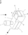
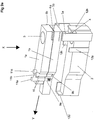
- the closure device in turn has a first connection module 1a, 1b and a second connection module 2, wherein the first connection module 1a, 1b consists of two parts, namely one as movable Slider formed, serving as an actuating element first module part 1a and a first module part 1a in the opening direction Y slidingly leading second module part 1b.
- first connection module 1a, 1b of the closure device can also be formed in one piece, analogous to the embodiment according to FIG Fig. 1a to 1e ,
- a magnet 3 is arranged, which in the closed position ( Fig. 2a ) frontally facing a magnet 4 (or magnetic armature) on the second connection module 2.
- first connection module 1a also locking pieces 6a, 6b are arranged, which are in the closed position with spring locking elements 5a, 5b on the second connection module 2 positively engaged and form a spring latch with the spring locking elements 5a, 5b.
- the Federverrastung and the strength of the magnets 3, 4 is in this case so dimensioned that the detent is automatically closed by the action of the magnetic attraction.
- the second module part 1b of the first connection module is connected via lateral guides 12a-12d in the closed position (FIG. Fig. 2a ) determined on the second connection module 2 that it is not relative to the second connection module 2, in particular not in the opening direction Y is movable. In the closed position, the first module part 1a is thus held together with the second module part 1b on the second connection module 2.
- the first module part 1a serving as an actuator is moved in the opening direction Y relative to the second module part 1b until the locking pieces 6a, 6b are disengaged from the spring locking members 5a, 5b (see FIG Fig. 2c ).
- the first module part 1a and the second module part 1b are locked together by a locking device realized by locking elements 9a, 9b, 9c and actuating pins 11a, 11b, 11c, so that opening of the closure device is only possible if the locking device previously has been unlocked ( Fig. 2b ).
- a plurality of locking elements 9a, 9b, 9c are arranged on the second module part 1b, said locking elements being arranged via return springs 10a, 10b, 10c are biased relative to the second module part 1 b and in the closed position engage in associated recesses 90 of the locking of the first module part 1 a, so that the first module part 1 a can not be displaced relative to the second module part 1 b and thus in the opening direction Y relative to the second connection module 2 is fixed.
- the locking elements 9a, 9b, 9c can be disengaged from the recesses 90 to lock between the first module part 1a and the second module part 1b to solve. It stands in the in Fig. 1 a locking position shown not all the locking elements 9a, 9b, 9c with an associated recess into engagement, which is not visible from the outside by a user, which actuation pins 11a, 11b, 11c are actuated and which not and whether the individual locking elements 9a, 9b, 9c in the unactuated state or not in locking engagement and lock or unlock by the operation.
- the length of upper actuating pin 11a, 11b, 11c and lower locking element 9a, 9b, 9c is dimensioned so that only after an operation, the contact plane of upper actuating pin 11a, 11b, 11c and lower locking element 9a, 9b, 9c in the plane of displacement of first module part 1a and second module part 1b.
- Fig. 2b the closure device is shown in the unlocked state.
- the actuating pins 11b, 11c are depressed and the associated locking elements 9b, 9c unlocked.
- the first module part 1a is thus displaceable in the opening direction Y for opening the closure device.
- Fig. 2c shows the closure device after lateral displacement of the first module part 1a in the opening direction Y (which is directed transversely to the closing direction X) in unlatched position in which on the one hand the magnets 3, 4 are shifted from each other and on the other hand the spring latching of the locking pieces 6a, 6b and the spring locking elements 5a, 5b are disengaged laterally.
- the closure device is detachable in this state
- connection modules 1a, 1b, 2 are shown completely separated from each other in the open state.
- first module part 1a is returned to a position in which the locking pieces 6a, 6b with the spring locking elements 5a, 5b can be locked again to close the closure device.
- the provision can be made manually, by suitable design of the magnets 3, 4 (or anchor) or by additional return means, for example in the form of a mechanical return spring, the first module part 1a relative to the second module part 1b in the direction of Fig. 2e pretensioning shown rest position.
- the locking device of the embodiment according to Fig. 2a to 2f can be further developed by an opening means in the manner of a key after an aligned insertion by appropriately preformed pin in the intended manner, the locking elements 9a, 9b, 9c actuated.
- the locking elements 9a, 9b, 9c actuated.
- only the insertion and displacement (or twisting) of the opening means is required for opening.
- a locking element 9a, 9b, 9c can not only assume two positions, but for example three or more, so that unlocking takes place only when the respective locking element 9a, 9b, 9c has been pushed into the correct position, which greatly increases the number of possible combinations.
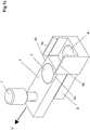
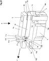
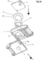
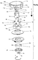
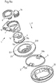
- Fig. 3b and 3c show in two exploded views the closure device with its individual parts obliquely from above ( Fig. 3b ) and diagonally from below ( Fig. 3c ).
- Part of the second connection module 2 is a spring locking element 5 in the form of a spreader, which is arranged on a base plate 20 so that the spring locking element 5 can switch to establish the closed state in the radial direction.
- a magnet 3 is disposed so as to be attractively opposed after closing to a magnet 4 on the first connection module 1 (male part).
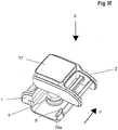
- the first connection module is attached in the closing direction X to the second connection module 2, so that the locking piece 6 with the spring locking element 5 is locked ( Fig. 3f ).
- the latching is produced by magnetic attraction of the magnets 3, 4 (one of which can also be embodied as a magnetic armature) as far as possible automatically when the first connection module 1 is attached to the second connection module 2.
- the spring locking element 5 in the form of the expansion ring has a lateral recess 53, so that the spring locking element 5 is not circumferentially closed, but is open to one side. This makes it possible, by moving the first connection module 1 relative to the second connection module 2 in the opening direction Y transversely to the closing direction X to push the spring locking element 5 out of engagement with the locking piece 6, so that the latching, positive connection of the first Connection module 1 is canceled with the second connection module 2 and the closure device can be solved. Due to the displacement in the opening direction Y, the magnets 3, 4 are at the same time removed from each other so that their magnetic attraction weakens and the first connection module 1 can be easily detached from the second connection module 2 in a haptically pleasant manner.
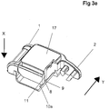
- a locking element 9 arranged on the second connecting module 2 engages in an associated recess 8 on the first connecting module 1 (see FIG Fig. 3c ) such that the first connection module 1 is locked against movement in the opening direction Y with the second connection module 2.
- the locking element 9 is elastically arranged on the second connection module 2 via a return spring 10a in the form of a resilient section, so that the locking is produced automatically when the first connection module 1 enters the closed position on the second connection module 2.
- actuating pin 11 is in operative connection with the locking element 9 on the first connection module 1 and acts upon actuation of the release button 17 by applying a compressive force in the closing direction X on the locking element 9 such that the locking element 9 out of engagement with the recess 8 on the second connection module. 2 arrives ( Fig. 3e ).
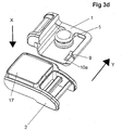
- Fig. 3d shows the first and second connection module 1, 2 after the shift in the opening direction Y.
- the connection modules 1, 2 are separated from each other, the closure device is open.
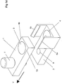
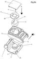
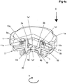
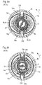
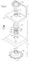
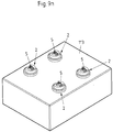
- FIG. 4g Another, in Fg. 4a to 4f in different partial sectional views and in Fig. 4g illustrated in an exploded view embodiment of a closure device is designed as a rotary closure, in which a first connection module 1 is mechanically locked in a closed position with a second connection module 2 and can be solved by turning a module part 1a in the form of a knob of the second connection module 2.
- the closure device has four magnets 3 a, 3 b, 4 a, 4 b, of which the magnets 3 a, 3 b are arranged on a base plate 20 of the second connection module 2 on a rotary core 1 a fixedly connected to the module part 1 a and the magnets 4 a, 4 b.
- the magnets 3a, 4a and 3b, 4b tighten in pairs, wherein by rotating the magnets to each other - analogous to that in the example WO 2008/006357 A2 is described - the magnetic attraction can be weakened and reversed in a magnetic repulsion.
- the first connection module 1 is composed of a rotatable functional subassembly, comprising the module part 1a in the form of the rotary knob and the rotary core 1a ', and a stationary functional subassembly consisting of a module part 1b and an annular abutment 1b' fixed against rotation therewith. together.
- the second connection module 2 has a fixed module part 23 on which a spring locking element 5 in the form of a spreader section open to the side and a base plate with the magnets 4a, 4b are arranged rotationally fixed.
- the spring locking element 5 has latching lugs 50a, 50b, which in a closed position with locking pieces 6a, 6b in the manner of locking lugs on the rotary core 1a 'positively engage and connect the first connection module 1 with the second connection module 2 in a form-locking manner.
- the magnets 3a, 3b and 4a, 4b are polarized in pairs in such a way that, when the first connection module 1 is attached to the second connection module 2 for closing the closure device in the closing direction X, unlike poles mutually attract each other and the rotation core 1a 'is rotated together with the module part 1a to effect a position in which the locking pieces 6a, 6b of the rotary core 1a 'with the locking lugs 50a, 50b of the spring locking element 5 can engage.
- Fig. 4a and Fig. 4d show the closure device in its closed position, wherein in Fig. 4d the over the spring locking element 5 and the locking pieces 6a, 6b made by positive Umgriff spring lock is visible.
- the magnets 3a, 3b of the rotary core 1a 'and the magnets 4a, 4b of the second connecting module 2 are frontally with unlike poles and thus attractively opposite.
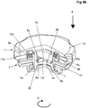
- a locking device is provided with arranged on the module part 1a, guided in recesses 14a-14f actuating pin 11a-11f, which are resiliently connected via return springs 10a-10f resiliently on the abutment 1b 'locking elements 9a-9f, wherein the locking elements 9a-9f lockingly engage in the recesses 14a-14f in a locking position and can be unlocked by actuation via the actuating pins 11a-11f.
- the locking device can realize a combination lock in which predetermined actuating pins 11a-11f must be actuated for unlocking, analogously as has been described above.
- the locking element 9a-9f is unconfirmed in unlocked position, i. it is so short that it releases the module part 1a in the unactuated state.
- Fig. 4b shows the locking device in the unlocked state after pressing the predetermined actuating pins 11a-11f, which unlock the locking elements 9a-9f such that the module part 1a can be rotated in the opening direction Y.
- the combination of the actuating pins 11a-11f and locking elements 9a-9f is thereby determined in advance during installation, in principle, by a key or a numeric code to be actuated embodiments of the locking device are conceivable, which may also be subsequently programmable, ie adjustable to a key or code.
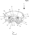
- Fig. 4c shows the closure device after a partial rotation of the first module part 1a and thus also of the rotary core 1a 'in the opening direction Y.
- the latch is still engaged in this position, and the magnets 3a, 3b, 4a, 4b are still attractively opposite.
- the locking pieces 6a, 6b of the rotary core 1a ' are disengaged from the locking lugs 50a, 50b of the spring locking element 5, so that the rotary core 1a' is removed from the second connecting module 2 and thus the first connecting module 1 in total - magnetically assisted by the repulsive force the mutually rotated magnets 3a, 3b, 4a, 4b - can be solved by the second connection module 2 in a simple and haptic pleasant way.
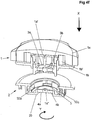
- Fig. 4f shows the closure device in the open state.
- the first connection module 1 can in turn be attached to the second connection module 2, wherein the rotary core 1 a 'is rotated by the attractive force of the magnets 3 a, 3 b, 4 a, 4 b into its latching required position and the latching is also produced automatically or almost automatically by the force acting between the magnets 3a, 3b, 4a, 4b attraction.
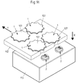
- the first connection module 1 three spring locking elements 5a, 5b, 5c with thread-shaped locking lugs 50a, 50b, 50c, which in the closed position with locking pieces 6a, 6b, 6c in the form of locking lugs on the second connection module 2 positively engage.
- the first connection module 1 is attached in the closing direction X to the second connection module 2, so that the Spring locking elements 5a, 5b, 5c engage with the locking pieces 6a, 6b, 6c of the second connection module 2 latchingly engaged.
- connection module 1 two magnets 3a, 3b and the second connection module 2 are arranged, which attract in pairs such that - analogous to the above with reference to the embodiment according to FIG Fig. 4a to 4g explained - the latching connection of the connection modules 1, 2 is produced automatically in a magnetically assisted manner, wherein the polarity of the magnets 3 a, 3 b, 4 a, 4 b simultaneously causes the connection modules 1, 2 in their connection to the latching Connection intended position to be rotated each other.
- the magnets 3a, 3b, 4a, 4b are pairwise frontally attractive.
- the first connection module 1 can be screwed in the opening direction Y relative to the second connection module 2, that the thread-shaped locking lugs 50a, 50b, 50c in the opening direction out of engagement with the likewise threaded locking pieces 6a, 6b, 6c are screwed.
- the magnets 3a, 3b, 4a, 4b are also rotated relative to one another, so that the magnetic attraction force acting in the closed position weakens and, in the open position, reverses into a repulsive force, so that the removal of the first connection module 1 from the second connection module 2 can be done in a magnetically assisted manner.
- a locking device in the form of a displaceably arranged on the first connection module 1
- bolt-shaped locking element 7 is provided, which engages locking in the locked position in a recess 8 on the second connection module 2 such that a rotation of the first connection module 1 relative to the second connection module 2 from the closed position not possible.
- the closure device is thus secured in the closed position, wherein the locking element 7 may be biased relative to the first connection module 1 (for example, via a mechanical spring), that the locking element 7 automatically enters its locking position when closing the closure device.
- the locking element 7 To open the closure device, the locking element 7 must first be actuated in order then to be able to rotate the connection modules 1, 2 against each other in the opening direction Y.
- Shuttering device shown are - analogous to that in the WO 2009/010049 A2 Shuttering device shown - on locking pieces 6a, 6b of a second connecting module 2, which in the closed position with locking lugs 50a, 50b of a spring locking element 5 on a first connection module 1 are positively engaged, kraftum whyde ramps 19a, 19b provided, the linear displacement of the first connection module 1 in the opening direction Y via spring legs 51a, 51b resilient latching noses 50a, 50b out of engagement with recesses 19 of the locking pieces 6a, 6b press.
- Fig. 6a shows the closure device in an exploded view.
- a longitudinally extending, wedge-shaped plug portion 18 is formed, which is used to produce the closed position in a connector receptacle 22 of the second connection module 2, so that the locking pieces 6a, 6b on the second connection module 2 side facing the plug portion 18 with the arranged on the connector receptacle 22 spring locking element 5, formed, for example, as a sheet metal spring engage.
- connection modules 1, 2 Two magnets 3 a, 3 b, 4 a, 4 b are arranged on the connection modules 1, 2, which face each other frontally in pairs in the closed position and are such that the latching connection of the connection modules 1, 2 is largely self-produced.
- the magnets 3a, 3b, 4a, 4b also cause the plug-in section 18 of the first connection module 1 and the plug receptacle 22 of the second connection module 2 to be brought into their intended position relative to one another when the closed position is produced, so that the latching lugs 50a, 50b of the Spring locking element 5 with the locking pieces 6a, 6b can engage positively.
- the first connection module 1 is moved relative to the second connection module 2 in the opening direction Y, so that the latching noses 50a, 50b run onto the ramps 19a and are thereby pressed out of engagement with the locking pieces 6a, 6b, so that the first Connection module 1 can be removed with its plug portion 18 from the connector receptacle 22 of the second connection module 2.
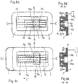
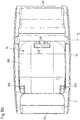
- Fig. 6b and 6c show the closure device in the closed position and in an open-shifted position
- Fig. 6d and 6e show the closure device in cross section along the line AA according to Fig. 6b or 6c
- Fig. 6f and 6g show the closure device in cross section along the line BB according to Fig. 6d or 6e
- Fig. 6h and 6i show the closure device in cross section along the line CC.
- the locking lugs 50a, 50b in positive engagement with the locking pieces 6a, 6b, and at the same time are the magnets 3a, 3b, 4a, 4b in pairs attractively frontally opposite (see Fig. 6h ).
- the first connection module 1 is moved in the opening direction Y ( Fig. 6c, 6e . 6g . 6i ), so that the locking lugs 50a, 50b are pressed by running onto the ramps 19a from the located below the locking pieces 6a, 6b recess 19 and the positive engagement is released (see Fig. 6g ).
- the magnets 3a, 3b, 4a, 4b are simultaneously displaced relative to one another, so that in the mutually displaced position (FIG. Fig. 6i ), the magnets 3a, 4b are repulsive with the same name poles and in the closed position ( Fig.
- connection modules 1, 2 The displacement of the connection modules 1, 2 from the closed position is blocked by a locking device in the form of a locking element 7, which is movably arranged on the first connection module 1, interlockingly engages in the locked position in a recess 8 on the second connection module 2 and for opening the closure device by pulling from the recess 8 is to be operated (see Fig. 6h and 6i ).
- the closure device according to 6a to 6i can be used for bags or satchels, for example.
- the connection modules 1 and 2 can be attached to a bag for this purpose, the attachment can be done in principle in various ways, eg. B. by sewing, gluing, riveting or screwing.
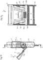
- FIG. 7a to 7g illustrated embodiment of a closure device is designed as a plug-in buckle, in which a first connection module 1 is designed as a plug receptacle and a second connection module 2 as a plug, each having a belt connection 64, 65 ( Fig. 7a ) for fastening a belt.
- Fig. 7a shows the closure device in a perspective view in the closed state, Fig. 7b in a side view, Fig. 7c in a sectional view along the line CC according to Fig. 7b and Fig. 7d in a sectional view taken along the line DD according to Fig. 7b ,
- Fig. 7a shows the closure device in a perspective view in the closed state
- Fig. 7b in a side view
- Fig. 7c in a sectional view along the line CC according to Fig. 7b
- Fig. 7d in a sectional view taken along the line DD according to Fig. 7b
- Fig. 7a shows the
- Fig. 7e are designed as an actuating element in the form of an actuating lever module part 1 b of the first Connection module 1 and the second connection module shown in separate views.
- Fig. 7f shows the closure device in a side view in a partially cutaway manner in the state actuated to the opening and Fig. 7g in a sectional view along the line CC according to Fig. 7f ,
- the first connection module 1 has a first module part 1a in the form of a housing and a second module part 1b in the form of an actuating lever, which is arranged pivotably about a pivot axis D on the first module part 1a.
- locking pieces 6a, 6b are provided (see Fig. 7c ), which in the closed position ( Fig. 7a . 7b, 7c, 7d ) are positively engaged with spring locking elements 5a, 5b in the form of latching lugs on the second connection module 2 and thus lock the first connection module 1 to the second connection module 2.
- the second module part 1 b can be pivoted in the form of the actuating lever of the first connection module 1, whereby the spring locking elements 5 a, 5 b arranged thereon bevels 52 a, 52 b accumulate on run-up slopes 19 a, 19 b on the module part 1 b and thereby, as in Fig. 7g shown, are pressed out of engagement with the locking pieces 6a, 6b.
- the ramps 19a, 19b, 52a, 52b of the spring locking elements 5a, 5b and the module part 1b are chamfered in a corresponding manner, so that upon a pivotal movement of the module part 1b about the pivot axis D in the opening direction Y, the run-up slopes 19a, 19b, 52a, 52b run each other and the resilient spring locking elements 5a, 5b out of engagement with the fixed locking pieces 6a, 6b press.
- the ramps 19a, 19b, 52a, 52b also act as ejection support in that they are in the actuated state ( Fig. 7g ) due to their slopes produce a force in the ejection direction (opposite to the closing direction X) and thus mechanically support the release of the closure device.
- a respective magnet 3, 4 arranged to point to each other with different poles and therefore tighten to produce the closed position and in the closed position of the closure device.
- the magnets 3, 4 are dimensioned so that when attaching the first connection module 1 to the second connection module 2, the latching connection of the spring locking elements 5a, 5b the locking pieces 6a, 6b is produced in an automatic manner, so that the closing of the closure device can be done easily and in a haptic pleasant manner.
- a locking device is provided in the form of a hook-like locking element 7 arranged movably on the module part 1b, which engages in the second connecting module 2 in the locked state such that the module part 1b is not pivoted about the pivot axis D relative to the second connecting module 2 can.
- the closure device is locked and secured in its closed position and can only be opened when the locking element 7 has been moved in the direction of displacement V from its locking engagement.
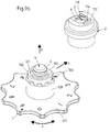
- FIG. 8a to 8f Shuttering device shown is designed as a closure for strap ends on backpacks or bags or for holding a Eispickels or the like to a backpack.
- the closure device has two connection modules 1, 2, of which the first connection module 1 is designed with a housing-like module part 1 b and a module part 1 a rotatable with respect to the module part 1 b in the form of an actuating element.
- the module part 1a has a rotary core 1a ', on which a locking piece 6 in the form of an annular detent nose on the second connecting module 2 facing the end of the rotary core 1a' is arranged.
- the locking piece 6 is in a closed position of the closure device form-fit with locking lugs 50a, 50b of an annular elastic spring locking element 5 into engagement, which is non-rotatably arranged on a base plate 20 of the second connection module 2.
- the base plate 20 is connected to a module part 23, wherein the latching noses 50a, 50b of the spring locking element 5 pass through recesses 230 of the module part 23.
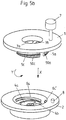
- Fig. 8a shows the closure device in an exploded view and Fig. 8b in a top view.
- Fig. 8c and Fig. 8d show cross-sectional views, wherein the closure device when shown in FIG Fig. 8c is in the closed position and in Fig. 8d is shown in the actuated state.
- 8e and 8f show sectional views along the line AA according to Fig. 8c or 8d.
- magnets 3 a, 3 b, 4 a, 4 b are arranged, which magnetically attract to close the closure device and are designed so that they produce the latching connection largely self-contained (in other words, the Magnets 3a, 3b, 4a, 4b dimensioned so that the magnetic attraction force exceeds the force required to produce the latching connection).
- the magnets 3a, 3b, 4a, 4b act also reset by turning the rotary core 1a 'by the action of the magnetic attraction force into a position in which the locking piece 6 can lock with the locking lugs 50a, 50b.
- the module part 1a can be rotated in the form of the rotatable actuating lever in the opening direction Y, whereby the rotary core 1a 'in the receiving opening 231 of the module part 23 is rotated.
- 6 bevels 19a and unlocking portions 19c are arranged on the rotary core 1a 'above the locking piece, which are such that upon rotation of the rotary core 1a' from the closed position ( Fig. 8e ) the locking lugs 50a, 50b accumulate on the ramps 19a and after rotation by a predetermined angle in the opening direction Y in the range of Entriegelungsabexcellente 19c reach.
- the magnets 3a, 3b, 4a, 4b Due to the rotation of the rotary core 1a ', the magnets 3a, 3b, 4a, 4b are simultaneously rotated relative to one another, so that in the unlatched position (FIG. Fig. 8d . 8f ), the magnets 3a, 4b and 3b, 4a with the same poles at least predominantly face and generate the opening supporting, repulsive magnetic force, so that the first connection module 1 can be removed in a light and pleasant way from the second connection module 2.
- the annular spring locking element 6 is designed with its ring section particularly soft resilient and thus offers a particularly soft feel while stable mechanical locking by transverse tension on the locking lugs 50a, 50b.
- the locking lugs 50a, 50b are each chamfered in such a way that they can engage the locking piece 6 in a locking manner in a locking manner in a locking manner in order to close the closure device in the closing direction.
- a locking device is according to the embodiment Fig. 8a to 8f realized by a locking element 7 in the form of a module part 1a movably arranged bolt which in the locked position ( Fig. 8c ) engages in a recess 8 on the module part 1a of the first connection module 1, so that the module part 1a can not be rotated relative to the second module part 1b.
- the locking element 7 To open the closure device, the locking element 7 must be actuated, ie pulled out of the recess 8 (FIG. Fig. 8d ), so that a rotation of the module part 1a is possible.
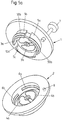
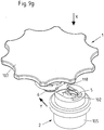
- Fig. 9a to 9k show different views of a further embodiment of a closure device in which the locking device is not formed by a separately arranged on one of the connecting module locking element, but by the engagement of a fixedly arranged on one of the connecting modules 1, 2 locking element 102 in a groove 101 on the other of Connection modules 1, 2, wherein the locking device can be unlocked by a rotational movement of the first connection module 1 in a unlocking direction Z (corresponding to a rotational direction) about the closing direction X.
- Fig. 9a shows an overview view here
- Fig. 9b and 9c show exploded views once diagonally from above and once diagonally from below
- Fig. 9d shows an exploded view in section
- Fig. 9e an exploded view from the side
- FIG. 9f and 9g the closure device in a dissolved state and Fig. 9h to 9k Sectional views of the closure device in the closed, locked state ( Fig. 9h ), in closed but unlocked state ( Fig. 9i ), in the open state ( Fig. 9j ) and before closing the closure device ( Fig. 9k ).
- the closure device according to Fig. 9a to 9k is fundamental to the nature of in Fig. 3a to 3f illustrated closure device formed.
- components of the same function provided with the same reference numerals, wherein additional components and, where appropriate, also in their function modified components are denoted by other reference numerals.
- the first connection module 1 in the closure device according to Fig. 9a to 9k has a locking piece 6 in the form of a protruding, an annular detent-bearing pin, which is adapted to engage with a arranged in a receptacle 114 on the second connection module 2 spring locking element 5 in the form of a laterally open ring member into engagement, as analogous above in connection with the embodiment according to Fig. 3a to 3f has been described.
- a magnet 4 and a base plate 20 of the second connection module 2 On the locking piece 6 of the first connection module 1, a magnet 4 and a base plate 20 of the second connection module 2, a magnet 3 is arranged, which cause a magnetic attraction between the connection modules 1, 2 and the transfer of the closure device in its closed state, in which the spring locking element 5 is mechanically latched with the locking piece 6, at least support.
- the closure device can in principle also be designed without magnetic means 3, 4 and in this case would be designed as a purely mechanical closure device.
- the magnetic means in the form of the magnets 3, 4 or on the one hand a magnet 3, 4 and on the other hand, a magnetic armature serve the magnetic support of the closing movement. If the magnetic means 3, 4 are dispensed with, the closing can be effected by applying the connecting modules 1, 2 to each other by external force application to produce the mechanical locking via the locking piece 6 and the spring locking element 5.
- the first connection module 1 is arranged on a component 112, for example the cover of a pocket, by the component 112 being held in a form-fitting manner between a module part 106 and a grip element 107, wherein the first connection module 1 is rotatable in an opening 117 to the component 112 ,
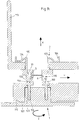
- the second connection module 2 is fixedly arranged on another component 113, for example the body of a bag, by the component 113 being connected between a holding element 104 and a collar 115 of a module part 105 of the second connection module 2 (see also FIG Fig. 9d and 9h ) is clamped against rotation.
- the first connection module 1 consists of the module part 106 and the non-rotatably connected to the module part 106 handle member 107, wherein the module part 106 via arranged on a cylindrical surface, axially extending webs 110 positively inserted into a recess 109 and arranged thereon, also axially extending grooves 111 is, so that the component 112 is held between the module part 106 and the handle member 107.
- the spring locking element 5 is latching and positively engaged with the locking piece 6 in engagement, so that the first connection module 1 can not be removed against the closing direction X of the second connection module 2.
- the arc-shaped locking element 102 arranged above on the end face of the second connection module 2 facing the first connection module 1 engages with the groove 101 on the first connection module, so that the first connection module 1 does not extend in the opening direction Y (which is transverse to the closing direction X) ) can be moved relative to the second connection module 2.
- the locking element 102 is in this locked, closed state in the groove 101, which by a collar 100 (see also Fig. 9a ) is limited to the outside.
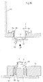
- the closure device By turning the first connection module 1 relative to the second connection module 2, the closure device enters the in Fig. 9i illustrated state in which the arranged on the second connection module 2 locking member 102 has been moved in the groove 101, that it comes to rest in the region of a recess 103 on the outer collar 100 and thus the locking member 102 is no longer blocked.
- the first connection module 1 can be moved in this position in the opening direction Y relative to the second connection module 2 by the locking piece 6 is moved through a side opening 118 of the receptacle 114 and removed from the engagement of the spring locking element 5.
- the thus opened state of the closure device is in Fig. 9j shown.
- the first connection module 1 has been moved in the opening direction Y relative to the second connection module 2 and thus disengaged from the second connection module 2.
- the closure device is thus opened.
- Fig. 9k shows the state before re-closing the closure device.
- the first connection module 1 can be attached in the closing direction X to the second connection module 2, whereby the locking piece 6 comes into locking engagement with the spring locking element 5 and thus produces a mechanical locking of the first connection module 1 with the second connection module 2.
- return means may be provided, for example, using a mechanical spring, the first connection module 1 in the in Fig. 9h pretend presented position.
- mechanical return means in the form of springs or the like but can also be provided that arranged on the first connection module 1 and the second connection module 2 magnets 3, 4 a magnetic attraction not only in the closing direction X, but also to the closing direction X (for example Using two magnet pairs differently polarized) effect, so that due to the magnetic means 3, 4, the first connection module 1 when attaching to the second connection module 2 automatically due to the magnetic forces acting in the desired locked position according to Fig. 9h is brought.
- the first and the second connection module 1, 2 may also be designed and arranged such that gravity preferably moves the two connection modules 1, 2 into the locked position.
- the first connection module 1 could be attached to a mobile telephone and the second connection module 2 to a belt holder.
- the locking element 102, the groove 101 and the collar 100 are then advantageously aligned so that the mobile phone normally such a pendulum vertically downwards hanging so that the connection modules 1, 2 are securely locked to each other (see position Fig. 9h ).
- To remove the mobile phone is then rotated and unlocked until it can be removed from its holder (particularly intuitive, this happens when the phone is rotated 180 ° and up from the holder (second connection module 2) is removed).
- the locking element 102 and the recess 103 are not exactly the same size, but the recess 103 is slightly larger in the circumferential direction, so that the unlocking of the connection modules can be carried out in a predetermined tolerance rotation angle range.
- closure device shown is suitable in an advantageous manner for forming a combination lock, due to the fact that from the outside with a suitable design and arrangement can not be seen in which position the closure device is unlocked.
- FIG. 9l to 9m An embodiment of such a combination lock show the views according to Fig. 9l to 9m , wherein in the illustrated embodiment, four closure devices of the type described above according to Fig. 9a to 9k have been combined by four first connection modules 1 and on a second component 113, four second connection modules 2 are arranged on a first component 112.
- the closure devices can be closed by attaching the connection modules 1, 2 to each other, as described above, wherein the closure devices can be opened in the closed state only by jointly moving the first connection modules 1 in the opening direction Y when the first connection modules 1 each in a unlocked position (see Fig. 9i ) have been brought.
- the opening direction Y is a linear displacement.
- the opening direction Y can also correspond to a rotational movement about a pivot point of the overall device.
- the recesses 103 of the individual connection modules 1 are in this case each tangent to concentric circles around this center (in the simplest case, all the recesses lie tangentially on a circle).
- the result is a device that can be opened only when correctly set combination on the connection modules 1, but is locked when only one of the connection modules 1 is in a locked state with the second connection module 2.
- connection modules 1, 2 and a different number of closure devices are conceivable, with increasing the number of connection modules 1, 2 increases the combinatory security.
- the first connection module 1 is constructed of a handle member 107 and a form-fitting inserted into this handle member 107 module part 106.
- the module part 106 can be inserted in different rotational positions about the closing direction X in the handle member 107, wherein the rotational position of the module part 106 the Position of the lateral recess 103 in the annular collar 100 relative to the handle member 107 can be specified.
- the position of the handle element 107 can be specified, in which the closure device is unlocked, in order in this way a numerical code for a combination lock of the Fig. 9I to 9m set to set.
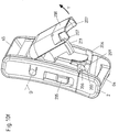
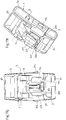
- FIG. 10a to 10f An embodiment of a closure device in the manner of a buckle is in 10a to 10f illustrated, wherein the closure device comprises a two module parts 1a, 1b existing first connection module 1 and a second connection module 2, which can be inserted with a plug element 200 in a receptacle 201 on the first module part 1a of the first connection module 1.
- the second module part 1 b of the first connection module 1 is mounted pivotably about an axis of rotation D on the first module part 1 a, wherein the second module part 1 b is composed of a closure element 209 and an actuating element 208.
- Magnetic means in the form of two magnets 3, 4 or in the form of a magnet and on the other hand a magnetic armature are magnetically supported on the plug element 200 of the second connection module 2 and on the closure element 209 of the first connection module 1, which magnetically support the transfer of the closure device into its closed state ,
- the first connection module 1 with the receptacle 201 arranged on the first module part 1a is attached to the plug element 200 of the second connection module 2 and pushed onto the plug element 200, so that latching elements 202, 203 arranged on the plug element 200 engage with an engagement nose 211 on the plug element 200 Closing element 209 of the second module part 1b engage.
- the latching lug 211 of the closure element 209 is inserted into an insertion opening 213 of the insertion element 200 and is latching with the latching elements 202, 203 in connection, so that the first connection module 1 can not be removed against the closing direction X of the second connection module 2.
- the latching elements 202, 203 are arranged on the plug-in element 200 of the second connection module 2, wherein the latching elements 202, 203 by spring elements 204, 205 on the first Module part 1a of the first connection module 1 are resiliently mounted. This will be described below with reference to the embodiment according to 11a to 11v be explained in more detail.
- the actuator 208 is slidably mounted to the closure member 209 via a slide guide 210 along a direction of unlocking Z, wherein the actuator 208 may be mechanically inserted into the in-molds using suitable spring means or magnetically using suitable magnetic means Fig. 10c shown position can be biased.
- the closure device In its basic operation, the closure device resembles 10a to 10f the embodiment of the closure device according to Fig. 7a to 7g ,
- the closure device can be opened by pivoting the second module part 1b consisting of the closure element 209 and the actuating element 208 about the axis of rotation D relative to the first module part 1a and moving it in the opening direction Y about the axis of rotation D.
- the engagement lug 211 of the closure element 209 is moved relative to the latching elements 202, 203 and disengaged therefrom so that the first connection module 1 can be removed from the second connection module 2 as soon as the engagement lug 211 is no longer in engagement with the latching elements 202, 203 stands.
- This condition is in Fig. 10f shown.
- the actuating element 208 of the second module part 1b of the first connection module 1 is in a position in which it engages with locking elements 206 on the second connection module 2 in a form-fitting manner via engagement elements 207 such that the second module part 1b does not move in the opening direction Y about the axis of rotation D can be swiveled.
- the locking device In the closed position according to Fig. 10c the locking device is locked with it and can not be opened easily.
- the second module part 1 b of the first connection module 1 can not be moved in the opening direction Y and, as a result, the engagement nose 211 can not be removed from the region of the latching elements 202, 203.
- end stops 212 of the actuating element 208 end in contact with the sliding guide 210 (see Fig. 10c ).
- the engagement elements 207 realize in this way, together with the locking elements 206, a locking device, which in the closed, locked state of the closure device, a movement of the second module part 1b of the first connection module 1 locks in the opening direction Y and counteracts an opening of the closure device.
- the locking can be released by bringing the engagement elements 207 out of engagement with the locking elements 206 on the second connecting module 2.
- the unlocked, but still closed state of the closure device is in Fig. 10d shown.
- the operating member 208 has been moved in the unlatching direction Z opposite to the closing direction X, and the engaging members 207 are thereby removed from engagement with the locking members 206.
- the second module part 1b (consisting of the actuating element 208 and the closure element 209) - as in Fig. 10e shown - are pivoted in the opening direction Y about the axis of rotation D, to bring in this way the engaging lug 211 out of engagement with the locking elements 202, 203 and to solve the mechanical locking between the connection modules 1, 2.
- connection modules 1, 2 can be removed from each other is in Fig. 10f shown.
- Fig. 11a to 11f show the closure device in the open state before closing
- 11g to 11th show the closure device when closing
- Fig. 11m to 11r show the closure device in the closed, locked state
- Figs. 11s and 11t show the closure device in the closed but unlocked state
- Figs. 11u and 11v show the closure device in the turn opened state.
- the closure device according to 11a to 11v differs from the closure device according to 10a to 10f essentially by the formation of the second module part 1b of the first connection module 1.
- the second module part 1b is integrally formed with two elastic arms 214 arranged thereon, each carrying an engagement element 207 for engagement with a locking element 206 on the second connection module 2.
- the arms 214 are sufficiently flexible and ensure a secure locking of the closure device in the closed, locked state.
- the arms 214 with the engaging elements 207 arranged thereon simultaneously ensure an automatic locking when the closing state of the closure device is established, when a suitable pretensioning of the second module part 1b into the in-situ mechanical or magnetic or by gravity Fig. 11a to 11e shown position is provided.
- This provision can be effected, for example, by magnets 3, 4 arranged on the second module part 1b and on the second connection module 2, which magnetically attract each other during the transfer of the closure device into the closed state and thus support the closing movement and automatically reset the second module part 1b in the in Fig. 11a to 11f cause shown position.
- the provision can also by a arranged on the first module part 1a of the first connection module 1 return anchor 31 (see Fig.11f ) in the form of a ferromagnetic armature (or by a corresponding return magnet) and arranged on the second module part 1b magnet 3 are magnetically attracted and thus automatically a provision of the second module part 1b in the in Fig. 11a to 11f cause shown position.
- Fig. 11g to 11l show the closure device when transferring the connection modules 1, 2 in its closed state.
- the latching elements 202, 203 are displaceably arranged on the second connection module 2, but are not mounted directly resiliently on the second connection module 2.
- the resilient mounting of the locking elements 202, 203 for the realization of the spring locking element 5 is rather via spring elements 204, 205, which are provided on the first module part 1 a of the first connection module 1. This has the purpose of allowing a slight mechanical locking of the connection modules 1, 2 during the transfer to the closed state, but at the same time to provide a secure, highly resilient mechanical latching when the closure state is established.
- the first connection module 1 with the receptacle 201 arranged thereon is attached to the plug-in element 200 of the second connection module 2.
- the engagement lug 211 is inserted into the insertion opening 213 on the plug element 200 until the engagement lug 211 comes into contact with the latching elements 202, 203, which are arranged transversely to the closing direction X displaceable on the second connection module 2.
- the spring elements 204, 205 Upon further attachment of the first connection module 1 to the plug element 200, however, the spring elements 204, 205 reach the back in contact with the latching elements 202, 203 and bias them inwardly in a direction towards each other such that after the engagement lug 211, the latching elements 202, 203 has happened, the positive engagement of the engaging lug 211 with the locking elements 202, 203 is made automatically.
- the spring elements 204, 205, the latching elements 202, 203 and the engagement lug 211 on a tilting can also be prevented during the production of the closed state, wherein in the closed state by the action of the spring elements 204, 205 on the latching elements 202, 203, the mechanical latching in Closed state is made safe.
- the result is a smooth and haptic pleasant closing process with automatic or almost automatic locking.
- the idea underlying the invention can basically be realized in other embodiments.
- the invention is independent of the action to be performed for the movement of the closure device, which can be rotational, tilting or sliding, wherein the connection modules are either moved as a whole against each other or operated by an actuator.
- the additional locking device may be formed as a simple trained locking element, but also as a combination lock or as a key to be operated lock.
- return means can effect the automatic return of the locking device to the locking position, for example by a biasing mechanical spring, by magnetic means or by gravity.
- connection modules in a position in which a latching engagement for producing the closed position is possible, can be done by additional return means, for example by using a mechanical spring, or also, as described above, by the magnetic effect of the already provided for magnets (or anchor) or by gravity.
- biasing, force-generating means can be used instead of the magnetic means, for example by spring means, or the gravity or an actuating force or a momentum can be exploited.
- a mechanical shutter which closes by attaching a first connection module to a second connection module in a closing direction by force (magnetic force, spring force, gravity) detent, wherein the first connection module against this closing direction are not easily removed from the second connection module but can be moved to open in a direction different from the closing direction opening direction, wherein a locking device prevents the displacement of the connection modules to each other in a locking position, but can be unlocked to open the closure.
- a closure device of the type described is suitable for a variety of different uses and advantageously used.
- the closure device can be used as a closure for bags, rucksacks, suitcases, furniture or other storage or transport or containers.
- the closure device may also be used to releasably connect components or flexible traction means such as ropes or straps (eg for mountaineering equipment or sailing equipment or even dog collars, towing ropes or other ropes or ropes), for attaching motorcycle or bicycle accessories to a motorcycle or bicycle (Such as for attaching saddlebags or other bags or bags, tools or the like) or for baby bowls, strollers or child carrier racks are used.
- the closure device may be used to attach mobile phones, weapons, batons or other utensils (e.g., police) to a belt mount.
Claims (14)
- Dispositif de fermeture, avec- un premier module de raccordement (1) et un deuxième module de raccordement (2), dans lequel le premier module de raccordement (1) peut être agencé dans une direction de fermeture au niveau du deuxième module de raccordement (2) et est enclenché mécaniquement dans une position de fermeture avec le deuxième module de raccordement (2), dans lequel pour ce faire au moins un élément de verrouillage à ressort (5, 5a, 5b, 5c) est agencé au niveau d'un parmi le premier module de raccordement (1) et le deuxième module de raccordement (2) et au moins une pièce de blocage (6, 6a, 6b) est agencée au niveau de l'autre parmi le premier module de raccordement (1) et le deuxième module de raccordement (2) pour la réalisation d'un enclenchement à ressort, dans lequel le premier module de raccordement (1) peut être désolidarisé du deuxième module de raccordement (2) par un déplacement du premier module de raccordement (1) ou d'une partie du premier module de raccordement (1) dans une direction d'ouverture, qui se distingue de la direction de fermeture, et- des moyens magnétiques (3, 4), qui provoquent une force d'attraction magnétique entre le premier module de raccordement (1) et le deuxième module de raccordement (2) pour soutenir le transfert du premier module de raccordement (1) dans la position de fermeture,caractérisé par
un dispositif de verrouillage déverrouillable (7 ; 9, 9a-f ; 100, 101, 102 ; 206, 207) pour empêcher un déplacement du premier module de raccordement (1) ou de la partie (1a) du premier module de raccordement (1) dans la direction d'ouverture (Y), lorsque le premier module de raccordement (1) et le deuxième module de raccordement (2) se trouvent dans la position de fermeture. - Dispositif de fermeture selon la revendication 1, caractérisé en ce que le déplacement dans la direction d'ouverture (Y) est un mouvement de translation transversalement à la direction de fermeture (X), un mouvement de rotation dans un plan transversalement à la direction de fermeture (X) ou un mouvement de pivotement autour d'un axe de rotation (D) transversalement à la direction de fermeture (X).
- Dispositif de fermeture selon la revendication 1 ou 2, caractérisé en ce que l'au moins un élément de verrouillage à ressort (5, 5a, 5b, 5c) et l'au moins une pièce de blocage (6, 6a, 6b, 6c) de l'enclenchement à ressort- sont décalés l'un par rapport à l'autre pour la désolidarisation du premier module de raccordement (1) du deuxième module de raccordement (2) de telle manière que l'au moins un élément de verrouillage à ressort (5, 5a, 5b, 5c) parvient le long de la direction d'ouverture (Y) de la zone de l'au moins une pièce de blocage (6, 6a, 6b, 6c), ou- sont décalés l'un par rapport à l'autre pour la désolidarisation du premier module de raccordement (1) du deuxième module de raccordement (2) de telle manière que l'au moins un élément de verrouillage à ressort (5, 5a, 5b, 5c) est poussé par montée sur un plan incliné (19a, 19b ; 52a, 52b) transversalement à la direction d'ouverture (Y) hors de prise avec l'au moins une pièce de blocage (6, 6a, 6b, 6c), ou- sont réalisés à la manière d'un filetage de telle manière que par rotation du premier module de raccordement (1) ou de la partie (1a) du premier module de raccordement (1) par rapport au deuxième module de raccordement (2) l'au moins un élément de verrouillage à ressort (5, 5a, 5b, 5c) et l'au moins une pièce de blocage (6, 6a, 6b, 6c) de l'enclenchement à ressort peuvent être vissés hors de prise.
- Dispositif de fermeture selon l'une quelconque des revendications précédentes, caractérisé en ce que les moyens magnétiques (3, 3a, 3b, 4, 4a, 4b) sont réalisés de telle manière que par le déplacement dans la direction d'ouverture (Y) la force d'attraction magnétique entre le premier module de raccordement (1) et le deuxième module de raccordement (2) est atténuée.
- Dispositif de fermeture selon l'une quelconque des revendications précédentes, caractérisé en ce que pour la réalisation des moyens magnétiques au niveau du premier module de raccordement (1) et au niveau du deuxième module de raccordement (2), respectivement au moins un aimant (3, 3a, 3b, 4, 4a, 4b) ou d'un côté au moins un aimant (3, 3a, 3b, 4, 4a, 4b) et de l'autre côté au moins un induit magnétique sont agencés, dans lequel par le déplacement dans la direction d'ouverture (Y) l'au moins un aimant (3, 3a, 3b) ou l'induit magnétique du premier module de raccordement (1) et l'au moins un aimant (4, 4a, 4b) ou l'induit magnétique du deuxième module de raccordement (2) sont déplacés l'un par rapport à l'autre de telle manière que la force d'attraction magnétique s'atténue.
- Dispositif de fermeture selon l'une quelconque des revendications précédentes, caractérisé en ce que le dispositif de verrouillage présente au moins un élément de verrouillage (7, 9, 9a-9f) agencé de manière mobile au niveau du premier module de raccordement (1) ou d'une partie (1a, 1b) du premier module de raccordement (1) pour la mise en prise dans un évidement (8) au niveau du deuxième module de raccordement (2) ou d'une deuxième partie (1b, 1a) du premier module de raccordement (1) de telle manière qu'un déplacement du premier module de raccordement (1) ou de la partie du premier module de raccordement (1) dans la direction d'ouverture (Y) est empêché pour la désolidarisation du premier module de raccordement (1) du deuxième module de raccordement (2).
- Dispositif de fermeture selon l'une quelconque des revendications précédentes, caractérisé en ce que le dispositif de verrouillage (7, 9, 9a-9f) est réalisé pour l'actionnement au moyen d'une clé ou d'un code numérique.
- Dispositif de fermeture selon l'une quelconque des revendications précédentes, caractérisé en ce que le dispositif de verrouillage (7, 9, 9a-9f) est réalisé pour se verrouiller automatiquement lors de l'agencement du premier module de raccordement (1) au niveau du deuxième module de raccordement (2).
- Dispositif de fermeture selon l'une quelconque des revendications précédentes, caractérisé en ce que le dispositif de verrouillage (100, 101, 102; 206, 207) est déverrouillable par un déplacement du premier module de raccordement (1) ou d'une partie (107 ; 208 ; 214) du premier module de raccordement (1) dans une direction de déverrouillage (Z).
- Dispositif de fermeture selon la revendication 9, caractérisé en ce que la direction de déverrouillage (Z) se distingue de la direction d'ouverture (Y) et n'est pas dirigée parallèlement à celle-ci.
- Dispositif de fermeture selon la revendication 9 ou 10, caractérisé en ce que le dispositif de verrouillage est formé par un élément de verrouillage (102) agencé au niveau du premier ou deuxième module de raccordement (1, 2), qui entre en prise dans un état fermé, verrouillé du dispositif de fermeture dans une rainure (101) au niveau de l'autre parmi le premier et deuxième module de raccordement (1,2).
- Dispositif de fermeture selon la revendication 11, caractérisé en ce que la direction d'ouverture (Y) est dirigée transversalement à la direction de fermeture (X) et la direction de déverrouillage (Z) est réalisée en tant que sens de rotation autour de la direction de fermeture (X), dans lequel l'élément de verrouillage (102) peut être amené hors de prise avec la rainure (101) par rotation du premier module de raccordement (1) ou d'une partie (107) du premier module de raccordement (1) dans la direction de déverrouillage (Z).
- Dispositif de fermeture selon la revendication 9 ou 10, caractérisé en ce que le premier module de raccordement (1) ou une partie (1b) du premier module de raccordement (1) peut être pivoté par rapport au deuxième module de raccordement (2) autour d'un axe de rotation (D) dirigé transversalement à la direction de fermeture (X) dans la direction d'ouverture (Y), dans lequel le dispositif de verrouillage (7 ; 206, 207) empêche dans l'état verrouillé un mouvement de pivotement du premier module de raccordement (1) ou d'une partie (1b) du premier module de raccordement (1).
- Dispositif de fermeture selon la revendication 13, caractérisé en ce que le dispositif de verrouillage est formé par un élément de verrouillage (206) agencé au niveau d'un parmi le premier et deuxième module de raccordement (1, 2) et un élément de mise en prise (207) agencé au niveau de l'autre parmi le premier et deuxième module de raccordement (1, 2) et en prise à l'état verrouillé avec l'élément de verrouillage (206), dans lequel le dispositif de verrouillage (206, 207) peut être déverrouillé par déplacement du premier module de raccordement (1) ou d'une partie (208 ; 214) du premier module de raccordement (1) dans une direction de déverrouillage (Z), qui se distingue de la direction d'ouverture (Y) et n'est pas dirigée parallèlement à celle-ci.
Applications Claiming Priority (4)
| Application Number | Priority Date | Filing Date | Title |
|---|---|---|---|
| DE102009038370 | 2009-08-24 | ||
| DE102010006798 | 2010-01-29 | ||
| DE202010010300U DE202010010300U1 (de) | 2009-08-24 | 2010-07-13 | Mechanischer Verschluss mit einer Verriegelungsvorrichtung |
| PCT/EP2010/062262 WO2011023661A1 (fr) | 2009-08-24 | 2010-08-23 | Fermeture mécanique dotée d'un dispositif de verrouillage |
Publications (2)
| Publication Number | Publication Date |
|---|---|
| EP2470041A1 EP2470041A1 (fr) | 2012-07-04 |
| EP2470041B1 true EP2470041B1 (fr) | 2017-10-04 |
Family
ID=42993961
Family Applications (1)
| Application Number | Title | Priority Date | Filing Date |
|---|---|---|---|
| EP10757402.2A Active EP2470041B1 (fr) | 2009-08-24 | 2010-08-23 | Fermeture mécanique dotée d'un dispositif de verrouillage |
Country Status (5)
| Country | Link |
|---|---|
| US (2) | US9572410B2 (fr) |
| EP (1) | EP2470041B1 (fr) |
| CN (2) | CN104116273B (fr) |
| DE (1) | DE202010010300U1 (fr) |
| WO (1) | WO2011023661A1 (fr) |
Cited By (1)
| Publication number | Priority date | Publication date | Assignee | Title |
|---|---|---|---|---|
| DE102022109723A1 (de) | 2022-04-22 | 2022-12-08 | Elvis Belov | Verschlussvorrichtung für Fahrzeuge |
Families Citing this family (65)
| Publication number | Priority date | Publication date | Assignee | Title |
|---|---|---|---|---|
| JP5511605B2 (ja) * | 2010-09-17 | 2014-06-04 | 株式会社パイオラックス | ハンドル装置 |
| US9554626B2 (en) * | 2011-09-09 | 2017-01-31 | Peter GELLERT | Easy release compound assemblies comprising a locking arrangement |
| DE102011086960A1 (de) | 2011-11-23 | 2013-05-23 | Fidlock Gmbh | Verschlussvorrichtung |
| DE202011052397U1 (de) | 2011-12-21 | 2012-01-17 | Fidlock Gmbh | Verschlussvorrichtung |
| CN103368021A (zh) * | 2012-04-03 | 2013-10-23 | 鸿富锦精密工业(深圳)有限公司 | 连接器固定装置 |
| CA2793264A1 (fr) * | 2012-10-19 | 2014-04-19 | John Nichol | Verrou a pene dormant |
| US11672729B2 (en) | 2014-02-11 | 2023-06-13 | Koya Medical, Inc. | Compression garment |
| US9271890B1 (en) | 2014-02-11 | 2016-03-01 | Compression Kinetics, Inc. | Compression garment apparatus |
| DE202014010491U1 (de) | 2014-05-26 | 2015-10-08 | Fidlock Gmbh | Fahrradsattelanordnung |
| US9141086B1 (en) * | 2014-08-11 | 2015-09-22 | Apple Inc. | Magnetic actuated attachment mechanisms for wearable devices |
| WO2016067152A1 (fr) * | 2014-10-30 | 2016-05-06 | Koninklijke Philips N.V. | Ensemble d'interconnexion et ensemble support comprenant celui-ci |
| US9750309B2 (en) | 2016-01-08 | 2017-09-05 | Nike, Inc. | Articles of footwear with an alternate fastening system |
| US9949532B2 (en) | 2015-05-15 | 2018-04-24 | Nike, Inc. | Articles of footwear with an alternate fastening system |
| TWM533700U (en) * | 2015-07-20 | 2016-12-11 | Peak Design Llc | Magnetic latching system |
| KR101811501B1 (ko) * | 2015-12-22 | 2017-12-20 | 백지숙 | 배낭의 가슴멜방용 버클 |
| DE102016208412B4 (de) * | 2016-02-03 | 2023-02-09 | Carsten Hoffmann | Tragesystem zum tragen eines gegenstandes |
| CN107173921A (zh) * | 2016-03-09 | 2017-09-19 | 珠海阳光儿童用品有限公司 | 联动解锁扣具、安全防护装置及安全服衣襟 |
| US11039672B2 (en) * | 2016-04-01 | 2021-06-22 | Rodney Neill | Portable carrier for storing one or more objects and methods thereof |
| CN107432539A (zh) * | 2016-05-27 | 2017-12-05 | 陈孔国 | 旅行箱内里连接结构 |
| CN110366404B (zh) | 2017-02-16 | 2022-12-06 | 科亚医疗公司 | 加压服装 |
| CN106801547B (zh) * | 2017-03-20 | 2022-04-19 | 苏州锦璘金属有限公司 | 保险箱或保管箱的机械锁防撬安全保险机构 |
| US10206461B1 (en) * | 2017-04-13 | 2019-02-19 | Kuat Innovations Llc | Latch systems and methods for straps |
| US9955757B1 (en) * | 2017-06-08 | 2018-05-01 | Samuel Samuel Limited | Magnet buckle |
| US10470529B2 (en) * | 2017-06-21 | 2019-11-12 | Duraflex Hong Kong Limited | Magnet hook |
| CA3066332A1 (fr) * | 2017-06-26 | 2019-01-03 | Cavity Sliders Limited | Serrure de porte amelioree |
| US10807309B2 (en) * | 2017-11-17 | 2020-10-20 | 3D Systems, Inc. | Latching system for three dimensional print engine |
| US10874178B2 (en) | 2017-12-07 | 2020-12-29 | Wonderland Switzerland Ag | Magnetic buckling assembly |
| DE102018205929A1 (de) * | 2018-04-18 | 2019-10-24 | Fidlock Gmbh | Befestigungsvorrichtung mit einem Basisteil und einem Sperrteil |
| GB2576138A (en) * | 2018-07-20 | 2020-02-12 | Ruroc Ip Holdings Ltd | Communications system control unit and releasable attachment mechanism |
| US10221587B1 (en) * | 2018-08-17 | 2019-03-05 | Judah Bergman | System and method for preventing movement of a door lever |
| DE102018123026A1 (de) * | 2018-09-19 | 2020-03-19 | Fidlock Gmbh | Verschlussvorrichtung mit aneinander ansetzbaren Verschlussteilen |
| CN109339585A (zh) * | 2018-11-20 | 2019-02-15 | 深圳市爱康伟达智能医疗科技有限公司 | 一种带磁力的锁紧装置 |
| US10945476B2 (en) * | 2018-11-20 | 2021-03-16 | Shenzhen City Aikang Weida Intelligent medical technology co., ltd | Mechanical-magnetic locking device |
| CN109488136B (zh) * | 2018-11-23 | 2020-09-29 | 永康市固嘉科技有限公司 | 一种可稳固锁定的磁扣隐形皮具锁 |
| USD965409S1 (en) | 2018-12-12 | 2022-10-04 | Yeti Coolers, Llc | Latch portion |
| US10766672B2 (en) | 2018-12-12 | 2020-09-08 | Yeti Coolers, Llc | Insulating container |
| US11970313B2 (en) | 2018-12-12 | 2024-04-30 | Yeti Coolers, Llc | Insulating container |
| US11304481B1 (en) | 2019-02-25 | 2022-04-19 | Nomad Innovations, Llc | Buckle |
| KR102188857B1 (ko) | 2019-05-14 | 2020-12-09 | 주식회사 우진프라스틱 | 견고한 체결유지 기능과 용이한 체결해제 기능을 갖는 버클 |
| US10914098B2 (en) * | 2019-05-30 | 2021-02-09 | Digilock Asia Ltd. | Enclosure latch system |
| KR102450616B1 (ko) * | 2019-06-06 | 2022-10-05 | 원더랜드 스위처랜드 아게 | 자기 버클 어셈블리 |
| CN112211507A (zh) * | 2019-07-09 | 2021-01-12 | 金泰祥精密五金(昆山)有限公司 | 一种磁扣锁 |
| DE202019103812U1 (de) * | 2019-07-10 | 2020-10-14 | Sudhaus Gmbh | Schloss und Behälter mit einem solchen Schloss |
| CN112298442B (zh) * | 2019-07-15 | 2023-01-31 | 捷安特电动车(昆山)有限公司 | 自行车锁具 |
| CN112237315B (zh) | 2019-07-17 | 2023-09-29 | 明门瑞士股份有限公司 | 扣具 |
| CN117016924A (zh) | 2019-07-17 | 2023-11-10 | 明门瑞士股份有限公司 | 扣具 |
| CN211558995U (zh) * | 2019-09-18 | 2020-09-25 | 石狮市青灿兴五金工艺品有限公司 | 一种插扣式带头可拆卸的皮带扣及其皮带 |
| DE102019214282B3 (de) * | 2019-09-19 | 2021-02-11 | Fidlock Gmbh | Verschlussvorrichtung mit zwei mit einem Gehäusemodul verbindbaren Verschlussteilen |
| CN112572304B (zh) * | 2019-09-30 | 2022-12-09 | 比亚迪股份有限公司 | 锁止结构、滑板车及车辆 |
| US11096454B2 (en) * | 2019-09-30 | 2021-08-24 | Qing Can Xing Hardware Crafts Co., Ltd. | Double-sided usable belt buckle and belt thereof |
| DE102019215277A1 (de) * | 2019-10-02 | 2021-04-08 | Fidlock Gmbh | Verschlussvorrichtung mit aneinander ansetzbaren Verschlussteilen |
| CN112746778B (zh) * | 2019-10-30 | 2022-02-18 | 金泰祥精密五金(昆山)有限公司 | 一种箱包锁 |
| DE202020100438U1 (de) * | 2020-01-28 | 2021-04-29 | Sudhaus Gmbh | Schloss und Behälter mit einem solchen Schloss |
| DE102020201838A1 (de) * | 2020-02-14 | 2021-08-19 | Pohlig Gmbh | Einhand-Schnellverschluss |
| EP4138607A1 (fr) * | 2020-07-23 | 2023-03-01 | Koya Medical, Inc. | Boucle d'ancrage à accouplement rapide |
| CN114027591B (zh) * | 2020-09-09 | 2024-02-20 | 联扬塑胶(深圳)有限公司 | 拨动解锁的扣具装置 |
| WO2022056585A1 (fr) * | 2020-09-15 | 2022-03-24 | Magnettica Pty Ltd | Boucle de fixation magnétique |
| TWI740687B (zh) * | 2020-10-22 | 2021-09-21 | 東洋建蒼電機股份有限公司 | 機車解鎖控制系統 |
| USD979453S1 (en) | 2020-12-18 | 2023-02-28 | Lindarets, LLC | Buckle |
| DE102021100419A1 (de) * | 2021-01-12 | 2022-07-14 | Fidlock Gmbh | Behältnis mit einer Verschlussvorrichtung |
| DE102021110382A1 (de) * | 2021-04-23 | 2022-10-27 | Multivac Sepp Haggenmüller Se & Co. Kg | Siegelstation mit einer Produktschutzplatte |
| DE102021206640A1 (de) | 2021-06-25 | 2022-12-29 | Fidlock Gmbh | Magnetische Verschlussvorrichtung mit einem Hemmelement |
| DE102021129074A1 (de) | 2021-11-09 | 2023-05-11 | Sudhaus Gmbh | Schließvorrichtung für ein Behältnis |
| US20240099429A1 (en) * | 2021-11-30 | 2024-03-28 | Fidlock Gmbh | Connecting Apparatus |
| US11945344B2 (en) | 2021-12-23 | 2024-04-02 | Artsana Usa, Inc. | Magnetic shoulder harness buckle for a child restraint |
Citations (3)
| Publication number | Priority date | Publication date | Assignee | Title |
|---|---|---|---|---|
| US4575908A (en) * | 1985-07-05 | 1986-03-18 | General Motors Corporation | Lock for seat belt buckle |
| US6694578B1 (en) * | 2003-05-15 | 2004-02-24 | Kimberly A. Nicoll | Child safety belt buckle locking mechanism |
| US20090031541A1 (en) * | 2007-07-27 | 2009-02-05 | Pribonic Edward M | Passenger restraint system |
Family Cites Families (11)
| Publication number | Priority date | Publication date | Assignee | Title |
|---|---|---|---|---|
| US4793032A (en) * | 1986-11-28 | 1988-12-27 | Illinois Tool Works, Inc. | Side release buckle |
| US4912950A (en) * | 1988-10-03 | 1990-04-03 | Illinois Tool Works, Inc. | Lockable buckle |
| EP0590206B1 (fr) * | 1991-06-14 | 1997-12-10 | TARMO CO. Ltd. | Fermoir |
| US5144725A (en) * | 1991-07-15 | 1992-09-08 | American Cord & Webbing, Inc. | Side-release buckle with accidental release guard |
| JPH0650523U (ja) * | 1992-12-22 | 1994-07-12 | 吉田工業株式会社 | 袋物・鞄などの蓋の係止具 |
| US5548879A (en) * | 1995-05-08 | 1996-08-27 | Wu; Chen-Chuan | Fastener device |
| WO2005120278A2 (fr) * | 2004-06-04 | 2005-12-22 | Gary Dunaye | Appareil fermoir magnetique |
| AU2007272165B2 (en) | 2006-07-12 | 2012-10-04 | Fidlock Gmbh | Mechanic-magnetic connecting structure |
| CN101646362B (zh) * | 2006-07-12 | 2012-12-12 | 菲德洛克有限责任公司 | 机械-磁连接结构 |
| WO2009010049A2 (fr) | 2007-07-17 | 2009-01-22 | Fidlock Gmbh | Structure d'assemblage mécano-magnétique |
| EP2252176B1 (fr) | 2008-01-27 | 2015-04-15 | Fidlock Gmbh | Serrure à aimant d'arrêt |
-
2010
- 2010-07-13 DE DE202010010300U patent/DE202010010300U1/de not_active Expired - Lifetime
- 2010-08-23 EP EP10757402.2A patent/EP2470041B1/fr active Active
- 2010-08-23 CN CN201410367015.1A patent/CN104116273B/zh active Active
- 2010-08-23 CN CN201080037853.2A patent/CN102481035B/zh active Active
- 2010-08-23 WO PCT/EP2010/062262 patent/WO2011023661A1/fr active Application Filing
- 2010-08-23 US US13/390,759 patent/US9572410B2/en active Active
-
2017
- 2017-01-06 US US15/400,429 patent/US10626636B2/en active Active
Patent Citations (3)
| Publication number | Priority date | Publication date | Assignee | Title |
|---|---|---|---|---|
| US4575908A (en) * | 1985-07-05 | 1986-03-18 | General Motors Corporation | Lock for seat belt buckle |
| US6694578B1 (en) * | 2003-05-15 | 2004-02-24 | Kimberly A. Nicoll | Child safety belt buckle locking mechanism |
| US20090031541A1 (en) * | 2007-07-27 | 2009-02-05 | Pribonic Edward M | Passenger restraint system |
Cited By (1)
| Publication number | Priority date | Publication date | Assignee | Title |
|---|---|---|---|---|
| DE102022109723A1 (de) | 2022-04-22 | 2022-12-08 | Elvis Belov | Verschlussvorrichtung für Fahrzeuge |
Also Published As
| Publication number | Publication date |
|---|---|
| CN104116273B (zh) | 2016-08-24 |
| CN104116273A (zh) | 2014-10-29 |
| WO2011023661A1 (fr) | 2011-03-03 |
| DE202010010300U1 (de) | 2010-10-21 |
| EP2470041A1 (fr) | 2012-07-04 |
| US9572410B2 (en) | 2017-02-21 |
| US10626636B2 (en) | 2020-04-21 |
| CN102481035B (zh) | 2015-02-04 |
| US20170114571A1 (en) | 2017-04-27 |
| US20120248793A1 (en) | 2012-10-04 |
| CN102481035A (zh) | 2012-05-30 |
Similar Documents
| Publication | Publication Date | Title |
|---|---|---|
| EP2470041B1 (fr) | Fermeture mécanique dotée d'un dispositif de verrouillage | |
| EP2531059B1 (fr) | Dispositif de fermeture | |
| EP2475278B1 (fr) | Dispositif de fermeture | |
| EP2833754B1 (fr) | Dispositif de fermeture pour relier deux pièces de manière détachable | |
| EP2389084B1 (fr) | Dispositif de fermeture destiné à relier deux pièces | |
| EP2475279B1 (fr) | Dispositif de fermeture | |
| EP2782468B1 (fr) | Dispositif de fermeture | |
| EP2040572B1 (fr) | Structure de liaison mécanico-magnétique | |
| EP2166895B1 (fr) | Structure d'assemblage mécano-magnétique | |
| DE102013000557B4 (de) | Magnetische Schließvorrichtung für Behältnisse, insbesondere für Weichgepäckstücke | |
| EP3852570B1 (fr) | Dispositif de fermeture avec pièces de fermeture pouvant être appliquées l'une contre l'autre | |
| DE102012222344A1 (de) | Verschlussvorrichtung zum Verbinden zweier Teile | |
| WO2021053230A1 (fr) | Dispositif de fermeture comprenant deux parties de fermeture pouvant être reliées à un module de logement | |
| DE102019215277A1 (de) | Verschlussvorrichtung mit aneinander ansetzbaren Verschlussteilen | |
| DE202011052397U1 (de) | Verschlussvorrichtung | |
| DE102022206461B3 (de) | Haltevorrichtung zum Halten eines Gegenstands an einer Baugruppe | |
| DE102022206462B3 (de) | Haltevorrichtung zum Halten eines Gegenstands an einer Baugruppe | |
| WO2023099264A1 (fr) | Fermeture de sangle de ceinture | |
| DE102018104228A1 (de) | Formhaltige Gepäckstücke | |
| EP4210533A1 (fr) | Appareil de liaison | |
| WO2023099265A1 (fr) | Dispositif de raccordement |
Legal Events
| Date | Code | Title | Description |
|---|---|---|---|
| PUAI | Public reference made under article 153(3) epc to a published international application that has entered the european phase |
Free format text: ORIGINAL CODE: 0009012 |
|
| 17P | Request for examination filed |
Effective date: 20120322 |
|
| AK | Designated contracting states |
Kind code of ref document: A1 Designated state(s): AL AT BE BG CH CY CZ DE DK EE ES FI FR GB GR HR HU IE IS IT LI LT LU LV MC MK MT NL NO PL PT RO SE SI SK SM TR |
|
| DAX | Request for extension of the european patent (deleted) | ||
| 17Q | First examination report despatched |
Effective date: 20151021 |
|
| RAP1 | Party data changed (applicant data changed or rights of an application transferred) |
Owner name: FIDLOCK GMBH |
|
| REG | Reference to a national code |
Ref country code: DE Ref legal event code: R079 Ref document number: 502010014230 Country of ref document: DE Free format text: PREVIOUS MAIN CLASS: A44B0011250000 Ipc: A45C0013120000 |
|
| RIC1 | Information provided on ipc code assigned before grant |
Ipc: E05B 13/10 20060101ALI20170323BHEP Ipc: E05B 37/12 20060101ALI20170323BHEP Ipc: A45C 13/10 20060101ALI20170323BHEP Ipc: E05B 65/52 20060101ALI20170323BHEP Ipc: A44B 11/25 20060101ALI20170323BHEP Ipc: E05B 37/16 20060101ALI20170323BHEP Ipc: E05B 47/00 20060101ALI20170323BHEP Ipc: A45C 13/12 20060101AFI20170323BHEP |
|
| GRAP | Despatch of communication of intention to grant a patent |
Free format text: ORIGINAL CODE: EPIDOSNIGR1 |
|
| INTG | Intention to grant announced |
Effective date: 20170510 |
|
| GRAA | (expected) grant |
Free format text: ORIGINAL CODE: 0009210 |
|
| GRAS | Grant fee paid |
Free format text: ORIGINAL CODE: EPIDOSNIGR3 |
|
| AK | Designated contracting states |
Kind code of ref document: B1 Designated state(s): AL AT BE BG CH CY CZ DE DK EE ES FI FR GB GR HR HU IE IS IT LI LT LU LV MC MK MT NL NO PL PT RO SE SI SK SM TR |
|
| REG | Reference to a national code |
Ref country code: GB Ref legal event code: FG4D Free format text: NOT ENGLISH |
|
| REG | Reference to a national code |
Ref country code: CH Ref legal event code: EP |
|
| REG | Reference to a national code |
Ref country code: AT Ref legal event code: REF Ref document number: 933197 Country of ref document: AT Kind code of ref document: T Effective date: 20171015 |
|
| REG | Reference to a national code |
Ref country code: IE Ref legal event code: FG4D Free format text: LANGUAGE OF EP DOCUMENT: GERMAN |
|
| REG | Reference to a national code |
Ref country code: DE Ref legal event code: R096 Ref document number: 502010014230 Country of ref document: DE |
|
| REG | Reference to a national code |
Ref country code: NL Ref legal event code: MP Effective date: 20171004 |
|
| REG | Reference to a national code |
Ref country code: LT Ref legal event code: MG4D |
|
| PG25 | Lapsed in a contracting state [announced via postgrant information from national office to epo] |
Ref country code: NL Free format text: LAPSE BECAUSE OF FAILURE TO SUBMIT A TRANSLATION OF THE DESCRIPTION OR TO PAY THE FEE WITHIN THE PRESCRIBED TIME-LIMIT Effective date: 20171004 |
|
| PG25 | Lapsed in a contracting state [announced via postgrant information from national office to epo] |
Ref country code: FI Free format text: LAPSE BECAUSE OF FAILURE TO SUBMIT A TRANSLATION OF THE DESCRIPTION OR TO PAY THE FEE WITHIN THE PRESCRIBED TIME-LIMIT Effective date: 20171004 Ref country code: ES Free format text: LAPSE BECAUSE OF FAILURE TO SUBMIT A TRANSLATION OF THE DESCRIPTION OR TO PAY THE FEE WITHIN THE PRESCRIBED TIME-LIMIT Effective date: 20171004 Ref country code: NO Free format text: LAPSE BECAUSE OF FAILURE TO SUBMIT A TRANSLATION OF THE DESCRIPTION OR TO PAY THE FEE WITHIN THE PRESCRIBED TIME-LIMIT Effective date: 20180104 Ref country code: LT Free format text: LAPSE BECAUSE OF FAILURE TO SUBMIT A TRANSLATION OF THE DESCRIPTION OR TO PAY THE FEE WITHIN THE PRESCRIBED TIME-LIMIT Effective date: 20171004 Ref country code: SE Free format text: LAPSE BECAUSE OF FAILURE TO SUBMIT A TRANSLATION OF THE DESCRIPTION OR TO PAY THE FEE WITHIN THE PRESCRIBED TIME-LIMIT Effective date: 20171004 |
|
| PG25 | Lapsed in a contracting state [announced via postgrant information from national office to epo] |
Ref country code: HR Free format text: LAPSE BECAUSE OF FAILURE TO SUBMIT A TRANSLATION OF THE DESCRIPTION OR TO PAY THE FEE WITHIN THE PRESCRIBED TIME-LIMIT Effective date: 20171004 Ref country code: IS Free format text: LAPSE BECAUSE OF FAILURE TO SUBMIT A TRANSLATION OF THE DESCRIPTION OR TO PAY THE FEE WITHIN THE PRESCRIBED TIME-LIMIT Effective date: 20180204 Ref country code: LV Free format text: LAPSE BECAUSE OF FAILURE TO SUBMIT A TRANSLATION OF THE DESCRIPTION OR TO PAY THE FEE WITHIN THE PRESCRIBED TIME-LIMIT Effective date: 20171004 Ref country code: GR Free format text: LAPSE BECAUSE OF FAILURE TO SUBMIT A TRANSLATION OF THE DESCRIPTION OR TO PAY THE FEE WITHIN THE PRESCRIBED TIME-LIMIT Effective date: 20180105 Ref country code: BG Free format text: LAPSE BECAUSE OF FAILURE TO SUBMIT A TRANSLATION OF THE DESCRIPTION OR TO PAY THE FEE WITHIN THE PRESCRIBED TIME-LIMIT Effective date: 20180104 |
|
| REG | Reference to a national code |
Ref country code: DE Ref legal event code: R097 Ref document number: 502010014230 Country of ref document: DE |
|
| PG25 | Lapsed in a contracting state [announced via postgrant information from national office to epo] |
Ref country code: CZ Free format text: LAPSE BECAUSE OF FAILURE TO SUBMIT A TRANSLATION OF THE DESCRIPTION OR TO PAY THE FEE WITHIN THE PRESCRIBED TIME-LIMIT Effective date: 20171004 Ref country code: SK Free format text: LAPSE BECAUSE OF FAILURE TO SUBMIT A TRANSLATION OF THE DESCRIPTION OR TO PAY THE FEE WITHIN THE PRESCRIBED TIME-LIMIT Effective date: 20171004 Ref country code: DK Free format text: LAPSE BECAUSE OF FAILURE TO SUBMIT A TRANSLATION OF THE DESCRIPTION OR TO PAY THE FEE WITHIN THE PRESCRIBED TIME-LIMIT Effective date: 20171004 Ref country code: EE Free format text: LAPSE BECAUSE OF FAILURE TO SUBMIT A TRANSLATION OF THE DESCRIPTION OR TO PAY THE FEE WITHIN THE PRESCRIBED TIME-LIMIT Effective date: 20171004 |
|
| PLBE | No opposition filed within time limit |
Free format text: ORIGINAL CODE: 0009261 |
|
| STAA | Information on the status of an ep patent application or granted ep patent |
Free format text: STATUS: NO OPPOSITION FILED WITHIN TIME LIMIT |
|
| REG | Reference to a national code |
Ref country code: FR Ref legal event code: PLFP Year of fee payment: 9 |
|
| PG25 | Lapsed in a contracting state [announced via postgrant information from national office to epo] |
Ref country code: IT Free format text: LAPSE BECAUSE OF FAILURE TO SUBMIT A TRANSLATION OF THE DESCRIPTION OR TO PAY THE FEE WITHIN THE PRESCRIBED TIME-LIMIT Effective date: 20171004 Ref country code: RO Free format text: LAPSE BECAUSE OF FAILURE TO SUBMIT A TRANSLATION OF THE DESCRIPTION OR TO PAY THE FEE WITHIN THE PRESCRIBED TIME-LIMIT Effective date: 20171004 Ref country code: PL Free format text: LAPSE BECAUSE OF FAILURE TO SUBMIT A TRANSLATION OF THE DESCRIPTION OR TO PAY THE FEE WITHIN THE PRESCRIBED TIME-LIMIT Effective date: 20171004 Ref country code: SM Free format text: LAPSE BECAUSE OF FAILURE TO SUBMIT A TRANSLATION OF THE DESCRIPTION OR TO PAY THE FEE WITHIN THE PRESCRIBED TIME-LIMIT Effective date: 20171004 |
|
| 26N | No opposition filed |
Effective date: 20180705 |
|
| PG25 | Lapsed in a contracting state [announced via postgrant information from national office to epo] |
Ref country code: MT Free format text: LAPSE BECAUSE OF FAILURE TO SUBMIT A TRANSLATION OF THE DESCRIPTION OR TO PAY THE FEE WITHIN THE PRESCRIBED TIME-LIMIT Effective date: 20171004 |
|
| PG25 | Lapsed in a contracting state [announced via postgrant information from national office to epo] |
Ref country code: SI Free format text: LAPSE BECAUSE OF FAILURE TO SUBMIT A TRANSLATION OF THE DESCRIPTION OR TO PAY THE FEE WITHIN THE PRESCRIBED TIME-LIMIT Effective date: 20171004 |
|
| PG25 | Lapsed in a contracting state [announced via postgrant information from national office to epo] |
Ref country code: MC Free format text: LAPSE BECAUSE OF FAILURE TO SUBMIT A TRANSLATION OF THE DESCRIPTION OR TO PAY THE FEE WITHIN THE PRESCRIBED TIME-LIMIT Effective date: 20171004 |
|
| REG | Reference to a national code |
Ref country code: CH Ref legal event code: PL |
|
| PG25 | Lapsed in a contracting state [announced via postgrant information from national office to epo] |
Ref country code: CH Free format text: LAPSE BECAUSE OF NON-PAYMENT OF DUE FEES Effective date: 20180831 Ref country code: LU Free format text: LAPSE BECAUSE OF NON-PAYMENT OF DUE FEES Effective date: 20180823 Ref country code: LI Free format text: LAPSE BECAUSE OF NON-PAYMENT OF DUE FEES Effective date: 20180831 |
|
| REG | Reference to a national code |
Ref country code: BE Ref legal event code: MM Effective date: 20180831 |
|
| PG25 | Lapsed in a contracting state [announced via postgrant information from national office to epo] |
Ref country code: BE Free format text: LAPSE BECAUSE OF NON-PAYMENT OF DUE FEES Effective date: 20180831 |
|
| REG | Reference to a national code |
Ref country code: AT Ref legal event code: MM01 Ref document number: 933197 Country of ref document: AT Kind code of ref document: T Effective date: 20180823 |
|
| PG25 | Lapsed in a contracting state [announced via postgrant information from national office to epo] |
Ref country code: AT Free format text: LAPSE BECAUSE OF NON-PAYMENT OF DUE FEES Effective date: 20180823 |
|
| PG25 | Lapsed in a contracting state [announced via postgrant information from national office to epo] |
Ref country code: TR Free format text: LAPSE BECAUSE OF FAILURE TO SUBMIT A TRANSLATION OF THE DESCRIPTION OR TO PAY THE FEE WITHIN THE PRESCRIBED TIME-LIMIT Effective date: 20171004 |
|
| PG25 | Lapsed in a contracting state [announced via postgrant information from national office to epo] |
Ref country code: PT Free format text: LAPSE BECAUSE OF FAILURE TO SUBMIT A TRANSLATION OF THE DESCRIPTION OR TO PAY THE FEE WITHIN THE PRESCRIBED TIME-LIMIT Effective date: 20171004 Ref country code: HU Free format text: LAPSE BECAUSE OF FAILURE TO SUBMIT A TRANSLATION OF THE DESCRIPTION OR TO PAY THE FEE WITHIN THE PRESCRIBED TIME-LIMIT; INVALID AB INITIO Effective date: 20100823 |
|
| PG25 | Lapsed in a contracting state [announced via postgrant information from national office to epo] |
Ref country code: IE Free format text: LAPSE BECAUSE OF NON-PAYMENT OF DUE FEES Effective date: 20180823 Ref country code: CY Free format text: LAPSE BECAUSE OF FAILURE TO SUBMIT A TRANSLATION OF THE DESCRIPTION OR TO PAY THE FEE WITHIN THE PRESCRIBED TIME-LIMIT Effective date: 20171004 Ref country code: MK Free format text: LAPSE BECAUSE OF NON-PAYMENT OF DUE FEES Effective date: 20171004 |
|
| PG25 | Lapsed in a contracting state [announced via postgrant information from national office to epo] |
Ref country code: AL Free format text: LAPSE BECAUSE OF FAILURE TO SUBMIT A TRANSLATION OF THE DESCRIPTION OR TO PAY THE FEE WITHIN THE PRESCRIBED TIME-LIMIT Effective date: 20171004 |
|
| P01 | Opt-out of the competence of the unified patent court (upc) registered |
Effective date: 20230517 |
|
| PGFP | Annual fee paid to national office [announced via postgrant information from national office to epo] |
Ref country code: GB Payment date: 20230824 Year of fee payment: 14 |
|
| PGFP | Annual fee paid to national office [announced via postgrant information from national office to epo] |
Ref country code: FR Payment date: 20230821 Year of fee payment: 14 Ref country code: DE Payment date: 20230822 Year of fee payment: 14 |