EP2929115B1 - Closure device for connecting two parts - Google Patents
Closure device for connecting two parts Download PDFInfo
- Publication number
- EP2929115B1 EP2929115B1 EP13817896.7A EP13817896A EP2929115B1 EP 2929115 B1 EP2929115 B1 EP 2929115B1 EP 13817896 A EP13817896 A EP 13817896A EP 2929115 B1 EP2929115 B1 EP 2929115B1
- Authority
- EP
- European Patent Office
- Prior art keywords
- closure
- closure part
- opening
- closure device
- relative
- Prior art date
- Legal status (The legal status is an assumption and is not a legal conclusion. Google has not performed a legal analysis and makes no representation as to the accuracy of the status listed.)
- Active
Links
- 230000005291 magnetic effect Effects 0.000 claims description 35
- 238000000926 separation method Methods 0.000 claims description 33
- 230000000903 blocking effect Effects 0.000 claims description 10
- 238000013016 damping Methods 0.000 claims description 7
- 230000005540 biological transmission Effects 0.000 claims description 3
- 230000000694 effects Effects 0.000 claims description 3
- 230000002238 attenuated effect Effects 0.000 claims description 2
- 230000007246 mechanism Effects 0.000 claims description 2
- 230000001846 repelling effect Effects 0.000 claims description 2
- 230000009471 action Effects 0.000 description 2
- 230000006835 compression Effects 0.000 description 2
- 238000007906 compression Methods 0.000 description 2
- 230000007704 transition Effects 0.000 description 2
- 230000008878 coupling Effects 0.000 description 1
- 238000010168 coupling process Methods 0.000 description 1
- 238000005859 coupling reaction Methods 0.000 description 1
- 239000003302 ferromagnetic material Substances 0.000 description 1
- 230000035939 shock Effects 0.000 description 1
- 239000007787 solid Substances 0.000 description 1
Images


Classifications
-
- E—FIXED CONSTRUCTIONS
- E05—LOCKS; KEYS; WINDOW OR DOOR FITTINGS; SAFES
- E05C—BOLTS OR FASTENING DEVICES FOR WINGS, SPECIALLY FOR DOORS OR WINDOWS
- E05C19/00—Other devices specially designed for securing wings, e.g. with suction cups
- E05C19/16—Devices holding the wing by magnetic or electromagnetic attraction
-
- E—FIXED CONSTRUCTIONS
- E05—LOCKS; KEYS; WINDOW OR DOOR FITTINGS; SAFES
- E05C—BOLTS OR FASTENING DEVICES FOR WINGS, SPECIALLY FOR DOORS OR WINDOWS
- E05C19/00—Other devices specially designed for securing wings, e.g. with suction cups
- E05C19/02—Automatic catches, i.e. released by pull or pressure on the wing
-
- Y—GENERAL TAGGING OF NEW TECHNOLOGICAL DEVELOPMENTS; GENERAL TAGGING OF CROSS-SECTIONAL TECHNOLOGIES SPANNING OVER SEVERAL SECTIONS OF THE IPC; TECHNICAL SUBJECTS COVERED BY FORMER USPC CROSS-REFERENCE ART COLLECTIONS [XRACs] AND DIGESTS
- Y10—TECHNICAL SUBJECTS COVERED BY FORMER USPC
- Y10T—TECHNICAL SUBJECTS COVERED BY FORMER US CLASSIFICATION
- Y10T292/00—Closure fasteners
- Y10T292/11—Magnetic
Definitions
- the invention relates to a closure device for connecting two parts according to the preamble of claim 1.
- Such a closure device comprises a first closure part and a second closure part.
- the second closure part can be attached to the first closure part in a closing direction for closing the closure device, is held in a closed position on the first closure part, is movable to open the closure device in a direction different from the closing direction opening direction to the first closure part and can after opening the Closing device for separating the closure parts against the closing direction are removed from the first closure part.
- the opening direction is different from the closing direction, it should be understood in the present case that the opening direction points in a direction other than the closing direction and in particular is also not directed opposite to the closing direction.
- the opening direction thus has an angle different to 0 ° and 180 ° to the closing direction.
- magnetic means are provided which act between the first closure member and the second closure member to assist closure of the closure device by providing a magnetic attractive force.
- Such a closure device is for example from the WO 2008/006357 A2 known.
- opening and separating the closure parts done in the manner of a circulation movement.
- To close the closure parts are attached in a closing direction to each other.
- To open the closure parts are moved along a different direction from the closing direction, for example, directed transversely to the closing direction opening direction to each other, so that a stop between the closure parts is released.
- the closure parts can then be separated from each other by being removed from each other in the opposite direction to the closing direction.
- For re-closing the closure parts can then be set again in the closing direction together.
- the individual actuation phases are present here as “closing” (corresponding to the attachment of the second closure part to the first closure part for closing the closure device), “opening” (corresponding to the opening of the closure device by moving the second closure part in the opening direction relative to the first closure part) and “Disconnect” (corresponding to the movement of the second closure member against the closing direction relative to the first closure member for removing the closure members from each other).
- closure device In the case of such a closure device, it can happen that, after opening the closure device and after a (small) separation path of the closure parts, the closure parts are returned to one another, ie, a movement of the second closure part against the opening direction relative to the first closure part, and the closure parts are automatically pulled back into the closing position due to the magnetic means, so that the closure device immediately closes again.
- This can be uncomfortable for a user, and the closure device may possibly be difficult to operate because the closure device accidentally snaps back after opening, so that the closure device must be opened again.
- Object of the present invention is to provide a closure device available in which the opening can be done in a haptic pleasant way and in particular a snap immediately after opening is not readily possible.
- locking means are provided in the closure device, which are designed to lock a back movement of the second closure part against the opening direction relative to the first closure part during separation of the closure parts.
- the present invention is based on the idea, when separating the closure parts from one another, that a return of the closure parts to one another, ie a return movement of the second closure part against the opening direction relative to the first closure part, can not take place directly and without further ado. Due to the fact that such a provision is blocked at least in sections when the closure parts are separated from each other, the second closure part can not directly reach a position relative to the first closure part, in which the second closure part is pulled again in the closing direction towards the first closure part. By means of the blocking means, snapping-on of the closure device immediately after opening during separation of the closure parts from one another is thus prevented, so that the closure parts can be reliably removed from each other and separated from each other at least over a predetermined path.
- the magnetic attraction is at least attenuated when opening the closure device.
- the magnetic means for example a magnet on the one closure part and a magnetic anchor of a ferromagnetic material on the other closure part or a magnet on each of the one and the other closure part - cause a magnetic attraction between the closure parts when the closure parts in a to be able to close suitable location.
- the magnetic means are advantageously dimensioned so that the closure of the closure device is largely automatic, so that a user must bring the closure parts only in a suitable positional relationship to each other and the Close then under the action of the magnetic means largely automatically goes on itself.
- the magnetic means are magnetically attractive and are approximated to each other, so that the magnetic attraction force is comparatively large.
- the magnetic means on the first closure part, on the one hand, and on the second closure part, on the other hand are then separated from each other, for example sheared off by a tangential sliding or twisting movement, so that the magnetic attraction of the magnetic means is weakened.
- a reversal of the magnetic force can be effected by the magnets repelling each other after opening. While in the closed position the magnets of the closure parts facing each other in pairs with unlike poles, the same poles of the magnets are approached when opening, so that the magnets act magnetically repulsive and thus magnetically support the separation of the closure parts after opening.
- means are provided which are designed to support the separation of the closure parts after opening the closure device magnetically or spring-mechanically.
- These means may be realized by the magnetic means themselves, as previously described, by the magnetic means acting magnetically repulsive after opening and thus magnetically assisting in the separation of the closure members.
- mechanical means for example a mechanical spring, can be provided which are mechanically biased during closing and / or opening and then cause an ejection force against the closing direction for mechanically assisted separation of the closure parts from each other after opening.
- means can be provided which bring about a return of the closure parts against the opening direction to a position in which the second closure part can be attached in the closing direction to the first closure part for closing the closure device, after the second closure part for separating the closure parts over a predetermined path against the closing direction has been moved relative to the first closure member.
- the return means can be realized, for example, by the magnetic means of the closure parts themselves, which, when the second closure part is re-attached to the first closure part, bring the closure parts into a position in which closure of the closure device is possible.
- the first closure part and the second closure part are mechanically locked together in the closed position. Due to the mechanical locking, the second closure part can not be moved counter to the closing direction from the closed position relative to the first closure part. Due to the mechanical latching the two closure parts are thus held together in the closed position, so that the closure device produces a secure, reliable, heavy-duty connection between the closure parts when the force is applied against the closing direction.
- the mechanical latching can be achieved by moving the second shutter member in the opening direction relative to the first shutter member by moving the mechanically latched members toward each other in the opening direction, for example, across the closing direction, so that the second shutter member disengages from the first shutter member ,
- one of the closure parts can, for example, have a detent spring element and the other of the closure parts can have at least one latching projection.
- the detent spring element and the at least one latching projection engage with one another in a mechanically latching manner, so that movement of the second closure part against the closed position is blocked relative to the first closure part.
- To open the second closure part can then be moved or rotated to the first closure part, so that the latching projection slides out of engagement with the detent spring element and the mechanical latching is thus canceled.
- the blocking means are formed by a slide guide track for guiding the second closure part at least in sections during opening of the closure device and / or during separation of the closure parts.
- the Sliding guide track has at least one contact section, which blocks a back movement of the second closure part against the opening direction relative to the first closure part during separation of the closure parts.
- the slide guide track is arranged on one of the closure parts and is engaged, for example, with a pin or another suitable positive locking element on the other of the closure parts. As a result of the engagement, the closure parts are guided relative to one another during opening and / or during separation, wherein the pin or the form-locking element is in contact with the contact section during separation and thus prevents backward movement of the second closure part against the opening direction.
- the gate guide track has a first gate section for guiding the second shutter part relative to the first shutter part in the closing direction when closing and a second gate guide section for guiding the second shutter part relative to the first shutter part in the opening direction when opening.
- a third slide guide section may be provided, which guides the second closure part relative to the first closure part against the closing direction during separation (after opening the closure device). The sliding guide track thus indicates the movement of the second closure part relative to the first closure part during closing, opening and optionally also during separation and thus describes the circulation movement that the second closure part relative to the first closure part first when closing, then when opening and finally during separation performs.
- the blocking means may also be formed by a latching guide which, when opened, establishes a mechanical latching connection of the closure parts for blocking a return movement of the second closure part against the opening direction relative to the first closure part.
- the latching guide engages at one of the closure parts, for example, with a latching hook on the other of the closure parts into engagement, wherein the engagement is such that the second closure part can not be moved back against the opening direction.
- the latching guide provides a guide against the closing direction for separating the closure parts from one another, so that after opening the closure parts can be separated from one another in a guided manner and thus removed from one another.
- the locking guide in this case provides a guide against the closing direction over a predetermined path. After the predetermined separation, the closure parts can be moved freely back to each other and thus be placed in a position to each other in which they can be put back to each other to close the closure device.
- the second closure part is connected to an actuating element and guided on the actuating element such that for opening the closure device, the actuating element is to move in an actuating direction different from the opening direction relative to the second closure part and the movement of the actuating element in a movement of the second closure part is converted in the opening direction.
- the actuating element By means of the actuating element, the second closure part can in this case be moved in the opening direction, wherein the actuating movement of the actuating element is different from the movement of the second closure part when opening.
- the actuator for actuating in an actuating direction is different from the opening direction to move, and due to the positive guidance, the actuating movement is converted into a movement of the second closure member in the opening direction.
- the direction of actuation should be different from the opening direction, is to be understood in the present case that the actuation direction and the opening direction are not rectified to each other, so describe an angle different 0 degrees to each other.
- the actuating direction - unlike the opening direction with respect to the closing direction - may also be directed opposite to the opening direction.
- the actuation direction may be the same or opposite to the closing direction, so that the actuating element for opening the closure device is to be moved in or counter to the closing direction relative to the second closure part.
- Such an actuating element can be used in an advantageous manner, for example when using the closure device on a piece of furniture, for example on a drawer, a sliding door or a swing door use.
- the actuating element can be connected, for example, integrally with a drawer, wherein by pressure on the drawer (in the closing direction) a movement of the second closure part in the opening direction (for example, transversely to the closing direction) is effected, so that by pressing the drawer, the closure device can be solved.
- this may look like a sliding door.
- the actuating element is for example formed integrally with the sliding door, so that the second closure part is moved in the opening direction (for example, transversely to the closing direction) by moving the sliding door in the closing direction.
- the second closure part may for example be forcibly guided on the actuating element via a guide device such that upon movement of the actuating element in the actuating direction the second closure part is moved in the opening direction relative to the first closure part.
- the guide device thus the movement of the actuating element in the actuating direction is converted into a movement of the second closure member in the opening direction
- the guide means may be formed, for example, as a slanted guide with at least one oblique guideway or as a thread guide with at least one thread groove.
- An oblique guide can be used in particular when the second closure part is to be displaced linearly (in a straight line) relative to the first closure part for opening.
- a thread guide can be used, for example, when the second closure part is to be moved to open in rotation relative to the first closure part.
- a forced operation or forced coupling for example, a gearbox using gears, a cable guide using a suitable cable drive, a parallelogram or a pivoting guide using a lever mechanism.
- damping means may be provided in an advantageous development, which are designed to damp a transmission of force from the actuating element to the second closure part upon movement of the actuating element in the actuating direction.
- a power transmission is thus not directly in a rigid manner, but in a damped manner via the damping means, which may be configured, for example, that between the actuating element and the second closure member elastically resilient (damping) elements are arranged.
- the damping means By means of the damping means can be prevented, for example, that in a shock or another Force on the actuator, which is not related to a conscious operation, no unwanted opening takes place.
- the damping means may be formed, for example, as a pneumatic or hydraulic damper, which acts at pulsed load damping between the actuating element and the second closure member and blocks a pulse-like force or at least brakes. This can ensure that e.g. when used on a sliding door in a vehicle actuation of the closure device can not be done in a vehicle braking or a crash or other impulsive load.
- the second closure part is connected to an actuating element and guided on the actuating element, that for opening the closure device, the actuating element is to be moved in an actuating direction different from the opening direction relative to the second closure part and the movement of the actuating element in a movement the second closure part is converted in the opening direction.
- closure device may also comprise blocking means, which are designed to lock a retraction of the second closure part against the opening direction relative to the first closure part during separation of the closure parts.
- a closure device of the type described above can be used, in particular, on furniture elements, for example sliding door devices or drawer devices. Accordingly, a furniture element, in particular a sliding door device or a drawer device, advantageously comprise a closure device of the type described above.
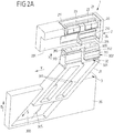
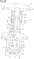
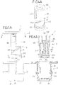
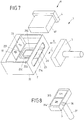
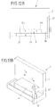
- Fig. 1 such as Fig. 2A to 2E show a first embodiment of a closure device 1, in which a first closure part 2 ("female” part) can be latchingly engaged with a second closure part 3 (“Male” part) in order, in a closed position, a mechanically strong, resilient connection between the closure parts 2, 3 produce.
- the first closure part 2 has a housing 20 and a detent spring element 21 arranged in a receiving opening 200 of the housing 20. At receiving openings 212, 213 of the detent spring element 21 magnets 22, 23 are arranged with the have different poles towards the second closure part 3.
- the detent spring element 21 also has two pairs of detent spring arms 210, 211, which are offset axially relative to one another along an opening direction Y, and which are also different in their height along a closing direction X, such as, for example Fig. 2A results.
- the second closure part 3 has a plug 311, on which two pairs of latching projections 312, 313 are arranged, which are each assigned to a pair of latching spring arms 210, 211 of the latching spring element 21.
- the pairs of latching projections 312, 313 are offset from one another along the closing direction X, corresponding to the offset in the height of the latching spring arms 210, 211, so that the pair of latching projections 312 are arranged below the pair of latching projections 313 along the closing direction X.
- the second closure part 3 is guided via a guide part 31 on a guide device 300 of an actuating element 30.
- the guide member 31 is in this case with webs 310 in the guide track 301 of the guide means 300 and is guided over the guide track 301 along an oblique direction S to the actuating element 30.
- a sliding guide track 32 is formed on the plug 311, which has a first link portion 320 and a second link portion 321 and a contact portion 322.
- the first link section 320 extends substantially along the closing direction X, while the second link section 321 extends along the opening direction Y.
- the plug 311 has two slotted guide tracks 32, which extend on both sides of the plug 311, namely on different sides of the plug 311 relative to a plane spanned by the closing direction X and the opening direction Y.
- the closure device 1 is used for releasably connecting two parts from each other.
- the closure device 1 may be part of a piece of furniture and serve for locking a sliding door, a drawer, a cabinet door or the like.
- One of the closure parts 2, 3, for example the first closure part 2 is in this case attached to a furniture body, while the other of the closure parts 2, 3, for example the second closure part 3, on the element to be adjusted, for example, the sliding door or the drawer is attached.
- the element to be adjusted for example, the drawer or the sliding door, held by the closure device 1 in a locking manner.
- the closure device 1 can then be opened, that is unlocked, to separate the closure parts 2, 3 from each other and open the element to be adjusted.
- Fig. 2A first shows the closure device 1 in a state before closing, in which the closure parts 2, 3 are present separately.
- the first closure part 2 (female part) and the actuating element 30 are in each case shown in a partial sectional view, in order to release the view into the inner receiving opening 200 of the housing 20 and the guide device 300.
- the second closure part 3 is attached to the first closure part 2 in the closing direction X (irrelevant is whether the first closure part 2 is stationary and the second closure part 3 is movable or conversely the second closure part 3 is stationary and the first closure part 2 is movable).
- the second closure part 3 is inserted into the receiving opening 200, wherein an inwardly projecting pin 24 dips into an associated gate guide track 32 of the plug 311 and first in the first gate section 320 of the slide guide track 32 passes (the receiving opening 200 has two opposing pins 24th each gate slot track 32 being associated with a pin 24, shown in FIG Fig. 2A and also in the following views 2B to 2E only one pin 24).
- two magnets 22, 23 are arranged, which are associated with two magnets 314, 315 on the plug 311.
- the magnets 22, 23 of the detent spring element 21 have different poles toward the associated magnets 314, 315 such that, for example, the magnet 22 has a north pole toward a south pole of the magnet 314 and the magnet 23 with a south pole toward a north pole of the magnet 315 points.
- the magnets 22, 23, 314, 315 magnetically attract, so that the closing of the closure device 1 magnetic supports and according to the connector 311 is pulled in the closing direction X in the receiving opening 200 of the housing 20.
- the closing is thus at least largely self-contained and thus in a haptic pleasant way for a user.
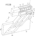
- Fig. 2B shows the closure device 1 in its closed position, in which the plug 311 is inserted into the receiving opening 200 and the pairs of latching projections 312, 313 of the plug 311 latching in engagement with the Rastfederarmen 210, 211 of the detent spring element 21.
- the pins 24 have passed through the first link section 320 of the respectively associated slide guide track 32 when closing and are now located at the break point between the first slide section 320 and the second slide section 321.
- the closure parts 2, 3 are thus latchingly connected to one another via the detent spring element 21 and the latching projections 312, 313 of the plug 31, so that the plug 311 can not be removed from the receiving opening 200 of the housing 20 against the closing direction X and the closure parts 2, 3 are thus held together in a solid, resilient manner.
- the second shutter member 3 is to be moved in the opening direction Y relative to the first shutter member 2 to disengage the latching projections 312, 313 in the opening direction Y from engagement with the associated latching spring arms 312, 313.
- the actuation of the second closure part 3 takes place here in the illustrated embodiment via the actuating element 30, on which the second closure part 3 is guided along the oblique guiding direction S.
- the second closure part 3 moves into the guide device 300 with its guide part 11 and is correspondingly moved in the opening direction Y due to the oblique guide provided by the guide device 300, so that the latching projections 312, 313 are moved relative to the detent spring arms 210, 211 and brought tangentially out of engagement therewith.
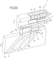
- Fig. 2C shows the closure device 1 in an open position.
- the pins 24 have been moved simultaneously in the respective associated guide slot track 32, wherein the pins 24 have each passed through the opening direction Y extending gate section 321.
- the magnets 22, 23, 314, 315 have also been displaced relative to each other along the opening direction Y at the same time.
- the magnets 23, 314 now face each other with poles of the same name, so that a magnetic repulsive force between the magnets 23, 314 counter to the closing direction X acts.
- a reset of the closure parts 2, 3 to each other, ie a return movement of the second closure member 3 against the opening direction Y in a position in which the closure parts 2, 3 again can be brought together with closing, is only possible if the second closure part 3 with his plug 311 has been moved out of the receiving opening 200 of the housing 20 of the first closure part 2 so far that the pins 24 are out of engagement with the abutment portions 322 of the plug 311 passes. This is in Fig. 2E shown.
- the plug 311 can in turn be brought into a position in which the magnets 22, 23, 314, 315 pairwise attractively facing and the pins 24 are in the gate sections 320 of the sliding guideways 32, so that the second closure part 3 turn in the closing direction X can be attached to the first closure part 2.
- This condition is the same as in Fig. 2A illustrated state.
- the biasing spring 305 may be formed, for example, as a compression spring which, when retracting the guide member 31 in the in Fig. 2C illustrated open position of the closure device 1 is stretched to pressure and for extending the second closure member 3 in the position according to Fig. 2A after opening and separation of the closure device 1 acts on the guide member 31.
- the result is a circulation movement, in which for closing the second closure part 3 in the closing direction X is attached to the first closure part 2, for opening the second closure part 3 is moved in the opening direction Y relative to the first closure part 2, for separating the second closure part 3 is moved counter to the closing direction X relative to the first closure part 2 and, for resetting, the second closure part 3 is again adjusted counter to the opening direction in its starting position.
- the actuating element 30 is also coupled to the second closure part 3 via a positive guide, there is an operation of the second closure part 3 for opening, which can be used advantageously in combination with a piece of furniture, eg a drawer or a sliding door use.
- the actuating element 30 may be formed integrally with a drawer, wherein the actuation of the closure device 1 is effected by pressure on the drawer and, accordingly, a movement of the actuating element 30 in the direction of actuation B corresponding to the closing direction X.
- the second closure member 3 By pressing the drawer (or according to the sliding door) thus the second closure member 3 can be moved in the opening direction Y, via the guide means 300 and the movement of the guide member 31 in the inclined direction S, the actuating movement of the actuating member 30 in the direction of actuation B in the Opening movement of the second closure part 3 is converted in the opening direction Y.
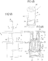
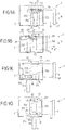
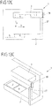
- FIG. 3A . 3B to 6A-6H Another embodiment of a closure device 1 is shown in FIG Fig. 3A . 3B to 6A-6H shown.
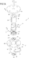
- Fig. 3A and Fig. 3B show here an exploded view and a partial sectional view of the closure device.
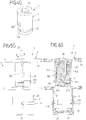
- Figs. 4A-4H, Figs. 5A-5H and 6A-6H show the closure device 1 in different views and different states, wherein Fig. 4A-4H perspective views, Fig. 5A-5H Side views and Figs. 6A-6H Sectional views along the line AA according to Fig. 5A-5H represent.
- the figures denoted by "A", "B", etc. represent the same state in each case, so that Figs. 4A, 5A and 6A a first state, 4B, 5B and 6B show a second state and so on.
- the closure device 1 has a first closure part 2 and a second closure part 3.
- the first closure part 2 comprises a housing 20, to which a semi-annular detent spring element 21 is attached in such a way that detent spring arms 210 engage through opposite recesses 201 and project into an inner receiving opening 200 of the housing 20.
- magnets 22, 23 are arranged, such as for example Fig. 2B seen.
- the second closure part 3 is guided on an actuating element 30 which is firmly connected to an actuating part 34.
- an actuating element 30 On a cylindrical lateral surface of the actuating element 30, two webs 302 are arranged, which extend axially along a closing direction X on the outside of the actuating element 30.
- a guide part 31 of the second closure part 3 is arranged and via two thread grooves 316 on threaded ridges 304 (see for example Fig. 3B ) guided.
- the guide member 31 are on both sides latching projections 312 radially outward before.
- a holding part 33 is connected to the holding openings 331, 332 magnets 314, 315 are held.
- the guide member 31 is connected to a bolt 35 in connection, which passes through a pin 340 of the actuating member 34 such that the guide member 31 along the closing direction X relative to the actuating member 34 is movable at least by a predetermined actuating travel. Due to the positive guidance provided via the thread grooves 316 and the thread ridges 304, this results in a relative movement of the guide member 31 to the actuating element 30 a Rotary movement of the guide member 31 relative to the actuator 30, as will be explained below.
- a sliding guide track 25 is arranged, which serves to guide a locking projection 312 and a web 302 and to different gate sections 250, 251, 252, 254 has.
- On the cylindrical inner wall of the receiving opening 200 are in this case (analogous to the two-sided slotted guide tracks 32 in the embodiment according to Fig. 1 and 2 ) arranged two slide guide tracks 25, which are arranged offset by 180 ° about the closing direction X on the inner wall of the receiving opening 200 and serve to guide a respective Rastvormenes 312 and web 302.
- closure device 1 The operation of the closure device 1 will be described below with reference to Figs. 4A-4H, 5A-5H and 6a-6H be explained.
- Figs. 4A, 5A and 6A the closure parts 2, 3 are separated from each other.
- the guide member 31 is hereby extended from the actuator 30, such as out Fig. 5A seen.
- the webs 302 and the latching projections 312 are aligned - as viewed along the closing direction X - in pairs with each other.
- biasing spring 305 (see Fig. 3B ), which acts between the actuator 30 and the guide member 31 and the second closure member 3 after opening and separation of the closure device 1 in the starting position according to Fig. 3A returns.
- the biasing spring 305 may be formed in this embodiment, for example, as a compression spring which is extended around the bolt 305, the bolt 305 surrounds and is arranged in a recess within the guide member 31.
- the detent spring arms 210 can deflect radially outward, so that the detent projections 312 urge the detent spring arms 210 aside and engage in detent engagement with the detent spring arms 210, as shown in FIG Figs. 4C, 5C and 6C is shown.
- the locking projections 312 engage behind the latch spring arms 210 so that the first closure part 2 and the second closure part 3 are mechanically locked together and the second closure part 3 can thus not (more) be removed from the first closure part 2 counter to the closing direction X.
- Closing is largely automatic due to the magnetic attraction between the magnets 22, 23, 314, 315.
- the magnets are 22, 23, 314, 315 in pairs opposite with opposite poles, so that the closure parts 2, 3 and magnetic held in position to each other.
- the actuating element 30 is pressed by pressing on the actuating part 34 in one of the closing directions X corresponding actuating direction B in the receiving opening 200 of the housing 20 of the first closure parts 2, as shown in Figs. 4D, 5D and 6D is shown. Due to the positive guidance between the actuating element 30 and the guide part 31 via the threaded guide realized by the thread grooves 316 and the thread legs 304, the guide part 31 is rotated in an opening direction Y (which is rotationally directed around the closing direction X), so that the latching projections 312 each move in a gate section 251 in a direction of movement V2 (see Fig. 3B ).
- the Guide member 31 is hereby rotated by a little less than 180 °, so that each locking projection 312 is moved towards the opposite sliding guide track 25 (in Fig. 3B only one slide guide track 25 is shown). If each latching projection 312 has reached the assigned slide section 252, then the latching projection 312 moves into the slide section 252 and moves in a direction of movement V3 counter to the closing direction X, also caused by the now repulsive magnets 22, 23, 314, 315, which have been rotated together with the guide member 31 are such that poles of the same name of the magnets 22, 23, 314, 315 in pairs face each other and thus repel.
- the latching projections 312 thus pass along the link sections 252 past the latching spring arms 210 of the latching spring element 21, so that the second closure part 3 can be removed from the receiving opening 200 of the housing 20 of the first closure part 2. This is in FIGS. 4E, 5E and 6E shown.
- the locking projections 312 can retract straight into the respective associated link section 252 of the opposite slide guide track 25.
- the latching projections 312 respectively come into abutment with a contact section 253 which laterally delimits the slotted section 252 and which causes the guide element 31 to not be pivoted back against the opening direction Y when the second closure part 3 is removed from the receiving opening 200.
- the abutment portions 253 of the two slide guide tracks 25 thus realize locking means for blocking a return movement of the guide member 31st
- the latching projections 312 continue to slide along the slide guide track 25 when the guide element 31 is removed, they enter the respectively assigned slide section 254 and are thus adjusted obliquely in a direction of movement V4 in the direction of the entry point 255 of the associated slide guide track 25. Because of this oblique guide, the guide member 31 is further rotated relative to the actuator 30, so that the guide member 31 is now rotated by exactly 180 ° relative to the actuator 30. In this position, the locking projections 312 and also the webs 302 emerge from the entry points 255 of the slide guide tracks 25, as shown in FIG Figs. 4F, 5F and 6F is shown.
- Locking means are also realized in this embodiment by two slide guide tracks 25, the abutment sections 253, which in the separation of the closure parts 2, 3 in front of each other (shown in FIG Fig. 4E, 5E, 6E and 4F, 5F, 6F ) Lock a return movement of the guide member 31 against the opening direction Y.
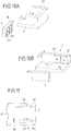
- FIG. 7, 8 and 9A to 9D illustrated another embodiment of a closure device 1 has two closure parts 2, 3, of which a second closure part 3 is at least partially enclosed by a first closure part 2 and with a handle 37 an opening 26 passes through.
- the second closure part 3 can be brought into different positions relative to the first closure part 2, but can not be completely detached from the first closure part 2.
- the second closure part 3 is located with a pin 36 (see Fig. 8 ) in a gate guide track 25 of the first closure part 2 and is guided in this way on the first closure part 2.
- the second closure part 3 is brought closer to a bottom 22 of the first closure part 2 in a closing direction X, with magnets 314, 315 of the second closure part 3 (see FIG Fig. 8 ) the magnets 22, 23 of the first closure part 2 with unlike poles face and thus a magnetic attraction during closing of the closure device 1 is effected.
- the pin 36 slides along a link portion 250 of the sliding guide track 25th
- Fig. 9A shows the closure device 1 in a closed position in which the second closure part 3 is magnetically held on the bottom of the first closure part 2 carrying the magnets 22, 23.
- an actuating element 4 can be moved in an actuating direction B in order to move the second closure part 3 in the direction of actuation B relative to the first closure part 2.
- the second closure part 3 slides with its pin 36 in a gate section 251 of the sliding guide track 25 and moves in an opening direction Y relative to the magnets 22, 23 supporting bottom of the first closure part 2, so that the same name magnets 22, 315 of the first closure part. 2 and the second closure part 3 are brought into opposing position and thus a magnetic repulsive force is effected, which causes a separation of the second closure part 3 from the bottom of the first closure part 2 supporting the magnets 22, 23 against the closing direction X.
- It runs, as in Fig. 9C shown, the pin 36 in a gate section 252, wherein the gate section 252 laterally limiting contact portion 253 prevents a return movement of the second closure member 3 against the opening direction Y.
- a closure device 1 two closure parts 2, 3.
- the closure parts 2, 3 are separated from each other (see 10A, 10B and 11th ).
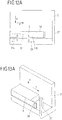
- Magnets 22, 23, 314, 315 are arranged on the closure parts 2, 3, which bring about a magnetic attraction force relative to one another, so that when the closure parts 2, 3 are attached to each other, a second closure part 3 automatically engages in the in Figs. 12A, 13A shown closed position is pulled.
- the magnets 22, 23, 314, 315 are magnetically attractive, so that the second closure part 3 is held on the first closure part 2.
- the second closure part 3 is moved in an opening direction Y relative to the first closure part 2 (see FIG Fig. 12B, 13B ).
- the magnets 22, 23 relative to the magnets 314, 315 tangentially shifted ("sheared off"), so that the magnetic attraction in the closed position is reversed in a repulsive force (see Fig. 12B ).
- a latching hook 38 of the second closure part 3 engages latchingly with a latching guide 27 of the first closure part 2, so that a return movement of the second closure part 3 against the opening direction Y is blocked.
- the locking guide 27 realized insofar a locking means.
- the latching guide 27 is designed such that a return movement of the second closure part 3 is locked against the opening direction Y, at the same time the closure parts 2, 3 but against the closing direction X can be separated from each other. The separation is assisted magnetically due to the repulsive force acting on separation, wherein due to the load guide 27, the closure parts 2, 3 can not immediately return to their closed position and thus the closure device 1 can not snap back immediately.
- Figs. 12C, 13C show the closure device 1 at separate closure parts 2, 3, the locking guide 27 releases the latching hook 38 after a separation movement by a distance H corresponding to the height of the latching guide 27 and the second experimental part 3 thus against the opening direction Y in the starting position according to Figs. 12D, 13D can be reset.
- This provision can be effected due to the acting magnetic forces between the magnets 22, 23, 314, 315.
- additional means for example in the form of a mechanical spring, which is tensioned when the closure device 1 is opened.
- a closure device of the type described above is advantageously used as a closure for furniture.
- the closure device can serve as a closure for furniture doors, drawers, sliding doors or the like.
- a closure device of the type described above can also be used as a closure for a bag, as a closure for a safety belt or for any other closures in which two parts securely and resiliently connected are to be and in which an opening in a lighter, haptic pleasant way should be possible to find use.
Description
Die Erfindung betrifft eine Verschlussvorrichtung zum Verbinden zweier Teile nach dem Oberbegriff des Anspruchs 1.The invention relates to a closure device for connecting two parts according to the preamble of
Eine derartige Verschlussvorrichtung umfasst ein erstes Verschlussteil und ein zweites Verschlussteil. Das zweite Verschlussteil ist zum Schließen der Verschlussvorrichtung in eine Schließrichtung an das erste Verschlussteil ansetzbar, wird in einer Schließstellung an dem ersten Verschlussteil gehalten, ist zum Öffnen der Verschlussvorrichtung in eine von der Schließrichtung unterschiedliche Öffnungsrichtung zu dem ersten Verschlussteil bewegbar und kann nach dem Öffnen der Verschlussvorrichtung zum Trennen der Verschlussteile entgegen der Schließrichtung von dem ersten Verschlussteil entfernt werden.Such a closure device comprises a first closure part and a second closure part. The second closure part can be attached to the first closure part in a closing direction for closing the closure device, is held in a closed position on the first closure part, is movable to open the closure device in a direction different from the closing direction opening direction to the first closure part and can after opening the Closing device for separating the closure parts against the closing direction are removed from the first closure part.
Darunter, dass die Öffnungsrichtung unterschiedlich von der Schließrichtung ist, soll vorliegend verstanden werden, dass die Öffnungsrichtung in eine andere Richtung als die Schließrichtung weist und insbesondere auch nicht entgegengesetzt zur Schließrichtung gerichtet ist. Die Öffnungsrichtung weist somit zur Schließrichtung einen Winkel unterschiedlich 0° und 180° auf.By the fact that the opening direction is different from the closing direction, it should be understood in the present case that the opening direction points in a direction other than the closing direction and in particular is also not directed opposite to the closing direction. The opening direction thus has an angle different to 0 ° and 180 ° to the closing direction.
Zusätzlich sind magnetische Mittel vorgesehen, die zwischen dem ersten Verschlussteil und dem zweiten Verschlussteil wirken, um das Schließen der Verschlussvorrichtung durch Bereitstellung einer magnetischen Anziehungskraft zu unterstützen.In addition, magnetic means are provided which act between the first closure member and the second closure member to assist closure of the closure device by providing a magnetic attractive force.
Eine derartige Verschlussvorrichtung ist beispielsweise aus der
Bei einer derartigen Verschlussvorrichtung erfolgen das Schließen, das Öffnen und das Trennen der Verschlussteile nach Art einer Kreislaufbewegung. Zum Schließen werden die Verschlussteile in eine Schließrichtung aneinander angesetzt. Zum Öffnen werden die Verschlussteile entlang einer von der Schließrichtung unterschiedlichen, beispielsweise quer zur Schließrichtung gerichteten Öffnungsrichtung zueinander bewegt, so dass ein Halt zwischen den Verschlussteilen aufgehoben wird. Nach dem Öffnen können die Verschlussteile dann voneinander getrennt werden, indem sie entgegen der Schließrichtung voneinander entfernt werden. Zum erneuten Schließen können die Verschlussteile dann wieder in die Schließrichtung aneinander angesetzt werden.In such a closure device closing, opening and separating the closure parts done in the manner of a circulation movement. To close the closure parts are attached in a closing direction to each other. To open the closure parts are moved along a different direction from the closing direction, for example, directed transversely to the closing direction opening direction to each other, so that a stop between the closure parts is released. After opening, the closure parts can then be separated from each other by being removed from each other in the opposite direction to the closing direction. For re-closing the closure parts can then be set again in the closing direction together.
Die einzelnen Betätigungsphasen werden vorliegend als "Schließen" (entsprechend dem Ansetzen des zweiten Verschlussteils an das erste Verschlussteil zum Schließen der Verschlussvorrichtung), "Öffnen" (entsprechend dem Öffnen der Verschlussvorrichtung durch Bewegen des zweiten Verschlussteils in die Öffnungsrichtung relativ zu dem ersten Verschlussteil) und "Trennen" (entsprechend der Bewegung des zweiten Verschlussteils entgegen der Schließrichtung relativ zum ersten Verschlussteil zum Entfernen der Verschlussteile voneinander) bezeichnet.The individual actuation phases are present here as "closing" (corresponding to the attachment of the second closure part to the first closure part for closing the closure device), "opening" (corresponding to the opening of the closure device by moving the second closure part in the opening direction relative to the first closure part) and "Disconnect" (corresponding to the movement of the second closure member against the closing direction relative to the first closure member for removing the closure members from each other).
Bei einer derartigen Verschlussvorrichtung kann es dazu kommen, dass nach dem Öffnen der Verschlussvorrichtung und nach einem (geringen) Trennweg der Verschlussteile es zu einer Rückstellung der Verschlussteile zueinander, also zu einer Bewegung des zweiten Verschlussteils entgegen der Öffnungsrichtung relativ zu dem ersten Verschlussteil, kommt und die Verschlussteile aufgrund der magnetischen Mittel selbsttätig wieder in die Schließstelle gezogen werden, so dass sich die Verschlussvorrichtung unmittelbar wieder schließt. Dies kann für einen Nutzer unangenehm sein, und die Verschlussvorrichtung kann gegebenenfalls schwierig zu betätigen sein, weil die Verschlussvorrichtung gegebenenfalls nach dem Öffnen ungewollt wieder zuschnappt, so dass die Verschlussvorrichtung erneut geöffnet werden muss.In the case of such a closure device, it can happen that, after opening the closure device and after a (small) separation path of the closure parts, the closure parts are returned to one another, ie, a movement of the second closure part against the opening direction relative to the first closure part, and the closure parts are automatically pulled back into the closing position due to the magnetic means, so that the closure device immediately closes again. This can be uncomfortable for a user, and the closure device may possibly be difficult to operate because the closure device accidentally snaps back after opening, so that the closure device must be opened again.
Aufgabe der vorliegenden Erfindung ist es, eine Verschlussvorrichtung zur Verfügung zu stellen, bei der das Öffnen auf haptisch angenehme Weise erfolgen kann und insbesondere ein Zuschnappen unmittelbar nach dem Öffnen nicht ohne Weiteres möglich ist.Object of the present invention is to provide a closure device available in which the opening can be done in a haptic pleasant way and in particular a snap immediately after opening is not readily possible.
Diese Aufgabe wird durch einen Gegenstand mit den Merkmalen des Anspruchs 1 gelöst.This object is achieved by an article having the features of
Demnach sind bei der Verschlussvorrichtung Sperrmittel vorgesehen, die ausgebildet sind, beim Trennen der Verschlussteile eine Zurückbewegung des zweiten Verschlussteils entgegen der Öffnungsrichtung relativ zum ersten Verschlussteil zu sperren.Accordingly, locking means are provided in the closure device, which are designed to lock a back movement of the second closure part against the opening direction relative to the first closure part during separation of the closure parts.
Die vorliegende Erfindung geht von dem Gedanken aus, beim Trennen der Verschlussteile voneinander dafür Sorge zu tragen, dass eine Rückstellung der Verschlussteile zueinander, also eine Zurückbewegung des zweiten Verschlussteils entgegen der Öffnungsrichtung relativ zu dem ersten Verschlussteil, nicht unmittelbar und ohne Weiteres erfolgen kann. Dadurch, dass eine solche Rückstellung zumindest abschnittsweise beim Trennen der Verschlussteile voneinander gesperrt ist, kann das zweite Verschlussteil nicht unmittelbar in eine Lage relativ zu dem ersten Verschlussteil gelangen, in der das zweite Verschlussteil wieder in die Schließrichtung hin zum ersten Verschlussteil gezogen wird. Mittels der Sperrmittel ist ein Zuschnappen der Verschlussvorrichtung unmittelbar nach dem Öffnen beim Trennen der Verschlussteile voneinander somit verhindert, so dass die Verschlussteile sicher voneinander entfernt und zumindest über einen vorbestimmten Weg voneinander getrennt werden können.The present invention is based on the idea, when separating the closure parts from one another, that a return of the closure parts to one another, ie a return movement of the second closure part against the opening direction relative to the first closure part, can not take place directly and without further ado. Due to the fact that such a provision is blocked at least in sections when the closure parts are separated from each other, the second closure part can not directly reach a position relative to the first closure part, in which the second closure part is pulled again in the closing direction towards the first closure part. By means of the blocking means, snapping-on of the closure device immediately after opening during separation of the closure parts from one another is thus prevented, so that the closure parts can be reliably removed from each other and separated from each other at least over a predetermined path.
Bei der Verschlussvorrichtung kann vorgesehen sein, dass beim Öffnen der Verschlussvorrichtung die magnetische Anziehungskraft zumindest abgeschwächt wird. Die magnetischen Mittel - beispielsweise ein Magnet an dem einen Verschlussteil und ein magnetischer Anker aus einem ferromagnetischen Material an dem anderen Verschlussteil oder ein Magnet jeweils an dem einen und an dem anderen Verschlussteil - bewirken eine magnetische Anziehungskraft zwischen den Verschlussteilen, wenn sich die Verschlussteile in einer zum Schließen geeigneten Lage gegenüber stehen. Die magnetischen Mittel sind dabei vorteilhafter Weise so dimensioniert, dass das Schließen der Verschlussvorrichtung weitestgehend selbsttätig erfolgt, so dass ein Nutzer die Verschlussteile nur in eine geeignete Lagebeziehung zueinander bringen muss und das Schließen dann unter Wirkung der magnetischen Mittel weitestgehend selbsttätig vor sich geht.In the closure device can be provided that the magnetic attraction is at least attenuated when opening the closure device. The magnetic means - for example a magnet on the one closure part and a magnetic anchor of a ferromagnetic material on the other closure part or a magnet on each of the one and the other closure part - cause a magnetic attraction between the closure parts when the closure parts in a to be able to close suitable location. The magnetic means are advantageously dimensioned so that the closure of the closure device is largely automatic, so that a user must bring the closure parts only in a suitable positional relationship to each other and the Close then under the action of the magnetic means largely automatically goes on itself.
In der Schließstellung stehen sich die magnetischen Mittel magnetisch anziehend gegenüber und sind aneinander angenähert, so dass die magnetische Anziehungskraft vergleichsweise groß ist. Zum Öffnen werden die magnetischen Mittel an dem ersten Verschlussteil einerseits und an dem zweiten Verschlussteil andererseits dann voneinander entfernt, beispielsweise durch eine tangentiale Verschiebe- oder Verdrehbewegung voneinander abgeschert, so dass die magnetische Anziehungskraft der magnetischen Mittel abgeschwächt wird.In the closed position, the magnetic means are magnetically attractive and are approximated to each other, so that the magnetic attraction force is comparatively large. For opening, the magnetic means on the first closure part, on the one hand, and on the second closure part, on the other hand, are then separated from each other, for example sheared off by a tangential sliding or twisting movement, so that the magnetic attraction of the magnetic means is weakened.
Sind an jedem Verschlussteil beispielsweise zwei Magnete angeordnet, die mit jeweils unterschiedlichen Polen zu dem Magneten an dem anderen Verschlussteil weisen, so kann beim Öffnen auch eine Umkehr der Magnetkraft bewirkt werden, indem die Magnete sich nach dem Öffnen voneinander abstoßen. Während in der Schließstellung die Magnete der Verschlussteile paarweise mit ungleichnamigen Polen aufeinander zu weisen, werden beim Öffnen gleichnamige Pole der Magnete einander angenähert, so dass die Magnete magnetisch abstoßend wirken und somit das Trennen der Verschlussteile nach dem Öffnen magnetisch unterstützen.If, for example, two magnets are arranged on each closure part and each have different poles to the magnet on the other closure part, a reversal of the magnetic force can be effected by the magnets repelling each other after opening. While in the closed position the magnets of the closure parts facing each other in pairs with unlike poles, the same poles of the magnets are approached when opening, so that the magnets act magnetically repulsive and thus magnetically support the separation of the closure parts after opening.
Vorteilhafterweise sind Mittel vorgesehen, die dazu ausgebildet sind, das Trennen der Verschlussteile nach dem Öffnen der Verschlussvorrichtung magnetisch oder federmechanisch zu unterstützen. Diese Mittel können durch die magnetischen Mittel selbst verwirklicht sein, indem - wie vorangehend beschrieben - die magnetischen Mittel nach dem Öffnen magnetisch abstoßend wirken und somit das Trennen der Verschlussteile magnetisch unterstützen. Es können zusätzlich oder alternativ aber auch mechanische Mittel, beispielsweise eine mechanische Feder, vorgesehen sein, die beim Schließen und/oder Öffnen mechanisch vorgespannt werden und nach dem Öffnen dann eine Auswurfkraft entgegen der Schließrichtung zum mechanisch unterstützten Trennen der Verschlussteile voneinander bewirken.Advantageously, means are provided which are designed to support the separation of the closure parts after opening the closure device magnetically or spring-mechanically. These means may be realized by the magnetic means themselves, as previously described, by the magnetic means acting magnetically repulsive after opening and thus magnetically assisting in the separation of the closure members. In addition or alternatively, however, mechanical means, for example a mechanical spring, can be provided which are mechanically biased during closing and / or opening and then cause an ejection force against the closing direction for mechanically assisted separation of the closure parts from each other after opening.
Weiterhin können Mittel vorgesehen sein, die eine Rückstellung der Verschlussteile entgegen der Öffnungsrichtung in eine Stellung, in der das zweite Verschlussteil in die Schließrichtung an das erste Verschlussteil zum Schließen der Verschlussvorrichtung angesetzt werden kann, bewirken, nachdem das zweite Verschlussteil zum Trennen der Verschlussteile über einen vorbestimmten Weg entgegen der Schließrichtung relativ zu dem ersten Verschlussteil bewegt worden ist. Sind die Verschlussteile voneinander getrennt worden, indem sie entgegen der Schließrichtung über den vorbestimmten Weg voneinander entfernt worden sind, so bewirken die beispielsweise magnetisch oder federmechanisch wirkenden Rückstellmittel eine Rückstellung der Verschlussteile zueinander, so dass die Verschlussteile wieder in eine Ausgangslage gelangen, in der das zweite Verschlussteil in die Schließrichtung an das erste Verschlussteil angesetzt werden kann, um die Verschlussvorrichtung zu schließen. Die Rückstellmittel können beispielsweise durch die magnetischen Mittel der Verschlussteile selbst verwirklicht sein, die bewirken, dass bei einem erneuten Ansetzen des zweiten Verschlussteils an das erste Verschlussteil die Verschlussteile in eine Lage zueinander gelangen, in der ein Schließen der Verschlussvorrichtung möglich ist.Furthermore, means can be provided which bring about a return of the closure parts against the opening direction to a position in which the second closure part can be attached in the closing direction to the first closure part for closing the closure device, after the second closure part for separating the closure parts over a predetermined path against the closing direction has been moved relative to the first closure member. Are the closure parts of each other have been separated by being removed against the closing direction over the predetermined path from each other, so cause, for example, magnetically or spring mechanically acting return means to a provision of the closure parts to each other, so that the closure parts return to an initial position in which the second closure member in the closing direction can be attached to the first closure part to close the closure device. The return means can be realized, for example, by the magnetic means of the closure parts themselves, which, when the second closure part is re-attached to the first closure part, bring the closure parts into a position in which closure of the closure device is possible.
In einer vorteilhaften Ausgestaltung sind das erste Verschlussteil und das zweite Verschlussteil in der Schließstellung mechanisch miteinander verrastet. Aufgrund der mechanischen Verrastung kann das zweite Verschlussteil nicht entgegen der Schließrichtung aus der Schließstellung relativ zum ersten Verschlussteil bewegt werden. Aufgrund der mechanischen Verrastung sind die beiden Verschlussteile somit in der Schließstellung aneinander gehalten, so dass die Verschlussvorrichtung bei Kraftwirkung entgegen der Schließrichtung eine sichere, zuverlässige, hochbelastbare Verbindung zwischen den Verschlussteilen herstellt. Die mechanische Verrastung kann durch Bewegen des zweiten Verschlussteils in die Öffnungsrichtung relativ zu dem ersten Verschlussteil gelöst werden, indem die mechanisch verrasteten Teile in die Öffnungsrichtung, beispielsweise quer zur Schließrichtung, zueinander bewegt werden, so dass das zweite Verschlussteil außer Eingriff von dem ersten Verschlussteil gelangt.In an advantageous embodiment, the first closure part and the second closure part are mechanically locked together in the closed position. Due to the mechanical locking, the second closure part can not be moved counter to the closing direction from the closed position relative to the first closure part. Due to the mechanical latching the two closure parts are thus held together in the closed position, so that the closure device produces a secure, reliable, heavy-duty connection between the closure parts when the force is applied against the closing direction. The mechanical latching can be achieved by moving the second shutter member in the opening direction relative to the first shutter member by moving the mechanically latched members toward each other in the opening direction, for example, across the closing direction, so that the second shutter member disengages from the first shutter member ,
Zum Verwirklichen der mechanischen Verrastung kann eines der Verschlussteile beispielsweise ein Rastfederelement und das andere der Verschlussteile zumindest einen Rastvorsprung aufweisen. In der Schließstellung stehen das Rastfederelement und der zumindest eine Rastvorsprung mechanisch rastend miteinander in Eingriff, so dass eine Bewegung des zweiten Verschlussteils entgegen der Schließstellung relativ zu dem ersten Verschlussteil gesperrt ist. Zum Öffnen kann das zweite Verschlussteil dann zu dem ersten Verschlussteil verschoben oder verdreht werden, so dass der Rastvorsprung außer Eingriff von dem Rastfederelement gleitet und die mechanische Verrastung somit aufgehoben wird.For realizing the mechanical latching, one of the closure parts can, for example, have a detent spring element and the other of the closure parts can have at least one latching projection. In the closed position, the detent spring element and the at least one latching projection engage with one another in a mechanically latching manner, so that movement of the second closure part against the closed position is blocked relative to the first closure part. To open the second closure part can then be moved or rotated to the first closure part, so that the latching projection slides out of engagement with the detent spring element and the mechanical latching is thus canceled.
Die Sperrmittel sind durch eine Kulissenführungsbahn zum zumindest abschnittsweisen Führen des zweiten Verschlussteils beim Öffnen der Verschlussvorrichtung und / oder beim Trennen der Verschlussteile ausgebildet. Die
Kulissenführungsbahn weist zumindest einen Anlageabschnitt auf, der beim Trennen der Verschlussteile eine Zurückbewegung des zweiten Verschlussteils entgegen der Öffnungsrichtung relativ zu dem ersten Verschlussteil sperrt. Die Kulissenführungsbahn ist an einem der Verschlussteile angeordnet und steht z.B. mit einem Zapfen oder einem anderen geeigneten Formschlusselement an dem anderen der Verschlussteile in Eingriff. Durch den Eingriff werden die Verschlussteile beim Öffnen und / oder beim Trennen relativ zueinander geführt, wobei der Zapfen oder das Formschlusselement beim Trennen in Anlage mit dem Anlageabschnitt ist und auf diese Weise eine Zurückbewegung des zweiten Verschlussteils entgegen der Öffnungsrichtung verhindert.The blocking means are formed by a slide guide track for guiding the second closure part at least in sections during opening of the closure device and / or during separation of the closure parts. The
Sliding guide track has at least one contact section, which blocks a back movement of the second closure part against the opening direction relative to the first closure part during separation of the closure parts. The slide guide track is arranged on one of the closure parts and is engaged, for example, with a pin or another suitable positive locking element on the other of the closure parts. As a result of the engagement, the closure parts are guided relative to one another during opening and / or during separation, wherein the pin or the form-locking element is in contact with the contact section during separation and thus prevents backward movement of the second closure part against the opening direction.
In einer konkreten Ausgestaltung weist die Kulissenführungsbahn einen ersten Kulissenabschnitt zum Führen des zweiten Verschlussteils relativ zu dem ersten Verschlussteil in die Schließrichtung beim Schließen und einen zweiten Kulissenführungsabschnitt zum Führen des zweiten Verschlussteils relativ zum ersten Verschlussteil in die Öffnungsrichtung beim Öffnen auf. Weiterhin kann ein dritter Kulissenführungsabschnitt vorgesehen sein, der das zweite Verschlussteil relativ zu dem ersten Verschlussteil entgegen der Schließrichtung beim Trennen (nach dem Öffnen der Verschlussvorrichtung) führt. Die Kulissenführungsbahn gibt somit die Bewegung des zweiten Verschlussteils relativ zu dem ersten Verschlussteil beim Schließen, beim Öffnen und gegebenenfalls auch beim Trennen vor und beschreibt somit die Kreislaufbewegung, die das zweite Verschlussteil relativ zum ersten Verschlussteil zunächst beim Schließen, dann beim Öffnen und schließlich beim Trennen ausführt.In a specific embodiment, the gate guide track has a first gate section for guiding the second shutter part relative to the first shutter part in the closing direction when closing and a second gate guide section for guiding the second shutter part relative to the first shutter part in the opening direction when opening. Furthermore, a third slide guide section may be provided, which guides the second closure part relative to the first closure part against the closing direction during separation (after opening the closure device). The sliding guide track thus indicates the movement of the second closure part relative to the first closure part during closing, opening and optionally also during separation and thus describes the circulation movement that the second closure part relative to the first closure part first when closing, then when opening and finally during separation performs.
Zusätzlich oder alternativ können die Sperrmittel auch durch eine Rastführung ausgebildet sein, die beim Öffnen eine mechanische Rastverbindung der Verschlussteile zum Sperren einer Zurückbewegung des zweiten Verschlussteils entgegen der Öffnungsrichtung relativ zum ersten Verschlussteil herstellt. Beim Öffnen gelangt die Rastführung an dem einen der Verschlussteile beispielsweise mit einem Rasthaken an dem anderen der Verschlussteile in Eingriff, wobei der Eingriff derart ist, dass das zweite Verschlussteil nicht entgegen der Öffnungsrichtung zurück bewegt werden kann.Additionally or alternatively, the blocking means may also be formed by a latching guide which, when opened, establishes a mechanical latching connection of the closure parts for blocking a return movement of the second closure part against the opening direction relative to the first closure part. When opening, the latching guide engages at one of the closure parts, for example, with a latching hook on the other of the closure parts into engagement, wherein the engagement is such that the second closure part can not be moved back against the opening direction.
Die Rastführung stellt hierbei gleichzeitig eine Führung entgegen der Schließrichtung zum Trennen der Verschlussteile voneinander bereit, so dass nach dem Öffnen die Verschlussteile in geführter Weise voneinander getrennt und somit voneinander entfernt werden können. Die Rastführung stellt hierbei eine Führung entgegen der Schließrichtung über einen vorbestimmten Weg bereit. Nach dem vorbestimmten Trennweg können die Verschlussteile wieder frei zueinander bewegt werden und somit auch in eine Lage zueinander gebracht werden, in der sie wieder an einander angesetzt werden können, um die Verschlussvorrichtung zu schließen.At the same time, the latching guide provides a guide against the closing direction for separating the closure parts from one another, so that after opening the closure parts can be separated from one another in a guided manner and thus removed from one another. The locking guide in this case provides a guide against the closing direction over a predetermined path. After the predetermined separation, the closure parts can be moved freely back to each other and thus be placed in a position to each other in which they can be put back to each other to close the closure device.
In einer vorteilhaften Ausgestaltung ist das zweite Verschlussteil mit einem Betätigungselement verbunden und derart an dem Betätigungselement geführt, dass zum Öffnen der Verschlussvorrichtung das Betätigungselement in eine Betätigungsrichtung unterschiedlich von der Öffnungsrichtung relativ zu dem zweiten Verschlussteil zu bewegen ist und die Bewegung des Betätigungselements in eine Bewegung des zweiten Verschlussteils in die Öffnungsrichtung umgesetzt wird. Dies geht von dem Gedanken aus, ein Betätigungselement vorzusehen, an dem das zweite Verschlussteil zwangsgeführt ist. Mittels des Betätigungselements kann das zweite Verschlussteil hierbei in die Öffnungsrichtung bewegt werden, wobei die Betätigungsbewegung des Betätigungselements unterschiedlich von der Bewegung des zweiten Verschlussteils beim Öffnen ist. So ist das Betätigungselement zum Betätigen in eine Betätigungsrichtung unterschiedlich von der Öffnungsrichtung zu bewegen, und aufgrund der Zwangsführung wird die Betätigungsbewegung in eine Bewegung des zweiten Verschlussteils in die Öffnungsrichtung umgesetzt.In an advantageous embodiment, the second closure part is connected to an actuating element and guided on the actuating element such that for opening the closure device, the actuating element is to move in an actuating direction different from the opening direction relative to the second closure part and the movement of the actuating element in a movement of the second closure part is converted in the opening direction. This is based on the idea of providing an actuating element on which the second closure part is forcibly guided. By means of the actuating element, the second closure part can in this case be moved in the opening direction, wherein the actuating movement of the actuating element is different from the movement of the second closure part when opening. Thus, the actuator for actuating in an actuating direction is different from the opening direction to move, and due to the positive guidance, the actuating movement is converted into a movement of the second closure member in the opening direction.
Darunter, dass die Betätigungsrichtung unterschiedlich von der Öffnungsrichtung sein soll, ist vorliegend zu verstehen, dass die Betätigungsrichtung und die Öffnungsrichtung nicht gleichgerichtet zueinander sind, also einen Winkel unterschiedlich 0 Grad zueinander beschreiben. Insbesondere kann die Betätigungsrichtung - anders als die Öffnungsrichtung mit Bezug auf die Schließrichtung - auch entgegengesetzt der Öffnungsrichtung gerichtet sein.The fact that the direction of actuation should be different from the opening direction, is to be understood in the present case that the actuation direction and the opening direction are not rectified to each other, so describe an angle different 0 degrees to each other. In particular, the actuating direction - unlike the opening direction with respect to the closing direction - may also be directed opposite to the opening direction.
Beispielsweise kann die Betätigungsrichtung der Schließrichtung gleich oder entgegen gerichtet sein, so dass das Betätigungselement zum Öffnen der Verschlussvorrichtung in die oder entgegen zur Schließrichtung relativ zu dem zweiten Verschlussteil zu bewegen ist.For example, the actuation direction may be the same or opposite to the closing direction, so that the actuating element for opening the closure device is to be moved in or counter to the closing direction relative to the second closure part.
Ein solches Betätigungselement kann in vorteilhafter Weise beispielsweise bei Verwendung der Verschlussvorrichtung an einem Möbelstück, beispielsweise an einer Schublade, einer Schiebtür oder einer Schwenktür Verwendung finden. Das Betätigungselement kann hierbei beispielsweise integral mit einer Schublade verbunden sein, wobei durch Druck auf die Schublade (in die Schließrichtung) eine Bewegung des zweiten Verschlussteils in die Öffnungsrichtung (beispielsweise quer zur Schließrichtung) bewirkt wird, so dass durch Druck auf die Schublade die Verschlussvorrichtung gelöst werden kann.Such an actuating element can be used in an advantageous manner, for example when using the closure device on a piece of furniture, for example on a drawer, a sliding door or a swing door use. In this case, the actuating element can be connected, for example, integrally with a drawer, wherein by pressure on the drawer (in the closing direction) a movement of the second closure part in the opening direction (for example, transversely to the closing direction) is effected, so that by pressing the drawer, the closure device can be solved.
Ähnlich kann dies bei einer Schiebetür aussehen. Dabei ist das Betätigungselement beispielsweise integral mit der Schiebetür ausgebildet, so dass durch Bewegung der Schiebetür in die Schließrichtung das zweite Verschlussteil in die Öffnungsrichtung (beispielsweise quer zur Schließrichtung) bewegt wird.Similarly, this may look like a sliding door. In this case, the actuating element is for example formed integrally with the sliding door, so that the second closure part is moved in the opening direction (for example, transversely to the closing direction) by moving the sliding door in the closing direction.
Das zweite Verschlussteil kann beispielsweise über eine Führungseinrichtung an dem Betätigungselement zwangsgeführt sein derart, dass bei einer Bewegung des Betätigungselements in die Betätigungsrichtung das zweite Verschlussteil in die Öffnungsrichtung relativ zum ersten Verschlussteil bewegt wird. Mittels der Führungseinrichtung wird somit die Bewegung des Betätigungselements in die Betätigungsrichtung in eine Bewegung des zweiten Verschlussteils in die Öffnungsrichtung umgesetzt, wobei die Führungseinrichtung beispielsweise als Schrägführung mit zumindest einer schrägen Führungsbahn oder als Gewindeführung mit zumindest einer Gewindenut ausgebildet sein kann. Eine Schrägführung kann insbesondere dann Verwendung finden, wenn das zweite Verschlussteil zum Öffnen linear (gradlinig) relativ zu dem ersten Verschlussteil zu verschieben ist. Eine Gewindeführung kann beispielsweise dann Verwendung finden, wenn das zweite Verschlussteil zum Öffnen drehend relativ zu dem ersten Verschlussteil zu bewegen ist.The second closure part may for example be forcibly guided on the actuating element via a guide device such that upon movement of the actuating element in the actuating direction the second closure part is moved in the opening direction relative to the first closure part. By means of the guide device thus the movement of the actuating element in the actuating direction is converted into a movement of the second closure member in the opening direction, wherein the guide means may be formed, for example, as a slanted guide with at least one oblique guideway or as a thread guide with at least one thread groove. An oblique guide can be used in particular when the second closure part is to be displaced linearly (in a straight line) relative to the first closure part for opening. A thread guide can be used, for example, when the second closure part is to be moved to open in rotation relative to the first closure part.
Grundsätzlich sind aber auch andere Ausgestaltungen einer Zwangsführung oder Zwangskopplung möglich, beispielsweise ein Getriebe unter Verwendung von Zahnrädern, eine Seilführung unter Verwendung eines geeigneten Seiltriebs, eine Parallelogrammführung oder eine Schwenkführung unter Verwendung eines Hebelgetriebes.In principle, however, other embodiments of a forced operation or forced coupling are possible, for example, a gearbox using gears, a cable guide using a suitable cable drive, a parallelogram or a pivoting guide using a lever mechanism.
Zwischen dem Betätigungselement und dem zweiten Verschlussteil können in einer vorteilhaften Weiterbildung Dämpfungsmittel vorgesehen sein, die dazu ausgebildet sind, eine Kraftübertragung von dem Betätigungselement auf das zweite Verschlussteil bei einem Bewegen des Betätigungselements in die Betätigungsrichtung zu dämpfen. Eine Kraftübertragung erfolgt somit nicht unmittelbar in starrer Weise, sondern in gedämpfter Weise über die Dämpfungsmittel, die beispielsweise dadurch ausgestaltet sein können, dass zwischen dem Betätigungselement und dem zweiten Verschlussteil elastisch federnde (dämpfende) Elemente angeordnet sind. Mittels der Dämpfungsmittel kann beispielsweise verhindert werden, dass bei einem Stoß oder einer anderen Krafteinwirkung auf das Betätigungselement, die nicht im Zusammenhang mit einer bewussten Betätigung steht, kein ungewünschtes Öffnen erfolgt.Between the actuating element and the second closure part damping means may be provided in an advantageous development, which are designed to damp a transmission of force from the actuating element to the second closure part upon movement of the actuating element in the actuating direction. A power transmission is thus not directly in a rigid manner, but in a damped manner via the damping means, which may be configured, for example, that between the actuating element and the second closure member elastically resilient (damping) elements are arranged. By means of the damping means can be prevented, for example, that in a shock or another Force on the actuator, which is not related to a conscious operation, no unwanted opening takes place.
Das Dämpfungsmittel kann beispielsweise als pneumatischer oder hydraulischer Dämpfer ausgebildet sein, der bei impulsartiger Belastung dämpfend zwischen dem Betätigungselement und dem zweiten Verschlussteil wirkt und eine impulsartige Krafteinwirkung sperrt oder zumindest bremst. Dadurch kann sichergestellt werden, dass z.B. bei einem Einsatz an einer Schiebtür in einem Fahrzeug eine Betätigung der Verschlussvorrichtung nicht bei einer Fahrzeugbremsung oder einem Crash oder einer anderen impulsartigen Belastung erfolgen kann.The damping means may be formed, for example, as a pneumatic or hydraulic damper, which acts at pulsed load damping between the actuating element and the second closure member and blocks a pulse-like force or at least brakes. This can ensure that e.g. when used on a sliding door in a vehicle actuation of the closure device can not be done in a vehicle braking or a crash or other impulsive load.
Der Gedanke, das zweite Verschlussteil an einem Betätigungselement zu führen, um das Öffnen der Verschlussvorrichtung durch Betätigen des Betätigungselements zu bewirken, stellt auch einen eigenständigen Gedanken dar, der auch unabhängig von den in Anspruch 1 genannten Sperrmitteln Verwendung finden kann. So umfasst eine Verschlussvorrichtung zum Verbinden zweier Teile dieser Art
- ein erstes Verschlussteil,
- ein zweites Verschlussteil, das zum Schließen der Verschlussvorrichtung in eine Schließvorrichtung an das erste Verschlussteil ansetzbar, in einer Schließstellung an den ersten Verschlussteil gehalten, zum Öffnen der Verschlussvorrichtung in eine von der Schließrichtung unterschiedliche Öffnungsrichtung zu dem ersten Verschlussteil bewegbar und nach dem Öffnen der Verschlussvorrichtung zum Trennen der Verschlussteile entgegen der Schließrichtung von dem ersten Verschlussteil entfernbar ist, und
- magnetische Mittel, die zwischen dem ersten Verschlussteil und dem zweiten Verschlussteil wirken, um das Schließen der Verschlussvorrichtung durch Bereitstellen einer magnetischen Anziehungskraft zu unterstützen.
- a first closure part,
- a second closure member adapted for closing the closure device in a closing device to the first closure member, held in a closed position to the first closure member for opening the closure device in a direction different from the closing direction opening direction to the first closure member and after opening the closure device for Separating the closure parts against the closing direction of the first closure part is removable, and
- magnetic means acting between the first closure member and the second closure member to assist closure of the closure device by providing a magnetic attractive force.
Dabei ist vorgesehen, dass das zweite Verschlussteil mit einem Betätigungselement verbunden und derart an dem Betätigungselement geführt ist, dass zum Öffnen der Verschlussvorrichtung das Betätigungselement in eine Betätigungsrichtung unterschiedlich von der Öffnungsrichtung relativ zu dem zweiten Verschlussteil zu bewegen ist und die Bewegung des Betätigungselements in eine Bewegung des zweiten Verschlussteils in die Öffnungsrichtung umgesetzt wird.It is provided that the second closure part is connected to an actuating element and guided on the actuating element, that for opening the closure device, the actuating element is to be moved in an actuating direction different from the opening direction relative to the second closure part and the movement of the actuating element in a movement the second closure part is converted in the opening direction.
Die vorangehend beschriebenen Vorteile und vorteilhaften Ausgestaltungen finden analog auch auf diese Verschlussvorrichtung Anwendung, wobei grundsätzlich die Merkmale der vorangehend erläuterten Unteransprüche auch in Kombination mit dieser Verschlussvorrichtung Verwendung finden können.The advantages and advantageous embodiments described above find analogous application to this closure device, where in principle the Features of the above-explained subclaims can also be used in combination with this closure device.
Insbesondere kann die Verschlussvorrichtung auch Sperrmittel aufweisen, die ausgebildet sind, beim Trennen der Verschlussteile ein Zurückbewegen des zweiten Verschlussteils entgegen der Öffnungsrichtung relativ zum ersten Verschlussteil zu sperren.In particular, the closure device may also comprise blocking means, which are designed to lock a retraction of the second closure part against the opening direction relative to the first closure part during separation of the closure parts.
Eine Verschlussvorrichtung der vorangehend beschriebenen Art kann insbesondere an Möbelelementen, beispielsweise Schiebetüreinrichtungen oder Schubladeneinrichtungen Verwendung finden. Entsprechend kann ein Möbelelement, insbesondere eine Schiebetüreinrichtung oder ein Schubladeneinrichtung, vorteilhafterweise eine Verschlussvorrichtung der vorangehend beschriebenen Art umfassen.A closure device of the type described above can be used, in particular, on furniture elements, for example sliding door devices or drawer devices. Accordingly, a furniture element, in particular a sliding door device or a drawer device, advantageously comprise a closure device of the type described above.
Der der Erfindung zugrunde liegende Gedanke soll nachfolgend anhand der in den Figuren dargestellten Ausführungsbeispiele näher erläutert werden. Es zeigen:
- Fig. 1
- eine Explosionsansicht eines ersten Ausführungsbeispiels einer Verschlussvorrichtung;
- Fig. 2A
- eine Ansicht der Verschlussvorrichtung vor dem Schließen;
- Fig. 2B
- eine Ansicht der Verschlussvorrichtung in einer Schließstellung;
- Fig. 2C
- eine Ansicht der Verschlussvorrichtung beim Öffnen;
- Fig. 2D
- eine Ansicht der Verschlussvorrichtung beim Trennen der Verschlussteile;
- Fig. 2E
- eine Ansicht der Verschlussvorrichtung bei getrennten Verschlussteilen;
- Fig. 3A
- eine Explosionsansicht eines zweiten Ausführungsbeispiels einer Verschlussvorrichtung;
- Fig. 3B
- eine Teilschnittansicht der Verschlussvorrichtung vor dem Schließen;
- Fig. 4A-4H
- perspektivische Ansichten der Verschlussvorrichtung in unterschiedlichen Zuständen;
- Fig. 5A-5H
- Seitenansichten der Verschlussvorrichtung in unterschiedlichen Zuständen;
- Fig. 6A-6H
- Schnittansichten entlang der Linie A-A in den jeweils zugehörigen
Figuren 5A-5H ; - Fig. 7
- eine Explosionsansicht eines weiteren Ausführungsbeispiels einer Verschlussvorrichtung;
- Fig. 8
- eine gesonderte Ansicht eines Verschlussteils der Verschlussvorrichtung gemäß
Fig. 7 ; - Fig. 9A-9D
- Ansichten der Verschlussvorrichtung in unterschiedlichen Zuständen;
- Fig. 10A
- eine erste Explosionsansicht eines weiteren Ausführungsbeispiels einer Verschlussvorrichtung;
- Fig. 10B
- die Explosionsansicht gemäß
Fig. 10A aus anderer Perspektive; - Fig. 11
- eine Seitenansicht der Verschlussvorrichtung beim Schließen;
- Fig. 12A-12D
- Seitenansichten der Verschlussvorrichtung in unterschiedlichen Zuständen; und
- Fig. 13A-13D
- perspektivische Ansichten der Verschlussvorrichtung in unterschiedlichen Zuständen.
- Fig. 1
- an exploded view of a first embodiment of a closure device;
- Fig. 2A
- a view of the closure device before closing;
- Fig. 2B
- a view of the closure device in a closed position;
- Fig. 2C
- a view of the closure device when opening;
- Fig. 2D
- a view of the closure device during the separation of the closure parts;
- Fig. 2E
- a view of the closure device with separate closure parts;
- Fig. 3A
- an exploded view of a second embodiment of a closure device;
- Fig. 3B
- a partial sectional view of the closure device before closing;
- Fig. 4A-4H
- perspective views of the closure device in different states;
- Fig. 5A-5H
- Side views of the closure device in different states;
- Figs. 6A-6H
- Sectional views along the line AA in the respectively associated
Figures 5A-5H ; - Fig. 7
- an exploded view of another embodiment of a closure device;
- Fig. 8
- a separate view of a closure part of the closure device according to
Fig. 7 ; - Figs. 9A-9D
- Views of the closure device in different states;
- Fig. 10A
- a first exploded view of another embodiment of a closure device;
- Fig. 10B
- the exploded view according to
Fig. 10A from another perspective; - Fig. 11
- a side view of the closure device when closing;
- Figs. 12A-12D
- Side views of the closure device in different states; and
- Figs. 13A-13D
- perspective views of the closure device in different states.
Das erste Verschlussteil 2 weist ein Gehäuse 20 sowie ein in einer Aufnahmeöffnung 200 des Gehäuses 20 angeordnetes Rastfederelement 21 auf. An Aufnahmeöffnungen 212, 213 des Rastfederelements 21 sind Magnete 22, 23 angeordnet, die mit unterschiedlichen Polen hin zu dem zweiten Verschlussteil 3 weisen. Das Rastfederelement 21 weist weiter zwei axial entlang einer Öffnungsrichtung Y zueinander versetzte Paare von Rastfederarmen 210, 211 auf, die zudem in ihrer Höhe entlang einer Schließrichtung X unterschiedlich sind, wie sich z.B. aus
Das zweite Verschlussteil 3 weist einen Stecker 311 auf, an dem zwei Paare von Rastvorsprüngen, 312, 313 angeordnet sind, die jeweils einem Paar von Rastfederarmen 210, 211 des Rastfederelements 21 zugeordnet sind. Die Paare von Rastvorsprüngen 312, 313 sind dabei, entsprechend dem Versatz in der Höhe der Rastfederarme 210, 211, entlang der Schließrichtung X zueinander versetzt, so dass das Paar von Rastvorsprüngen 312 entlang der Schließrichtung X unterhalb des Paares der Rastvorsprünge 313 angeordnet ist.The
Das zweite Verschlussteil 3 ist über ein Führungsteil 31 an einer Führungseinrichtung 300 eines Betätigungselements 30 geführt. Das Führungsteil 31 liegt hierbei mit Stegen 310 in Führungsbahn 301 der Führungseinrichtung 300 ein und ist über die Führungsbahn 301 entlang einer Schrägführungsrichtung S an dem Betätigungselement 30 geführt.The
Wie aus
Insgesamt weist der Stecker 311 zwei Kulissenführungsbahnen 32 auf, die sich beidseits des Steckers 311, nämlich an unterschiedlichen Seiten des Steckers 311 bezogen auf eine durch die Schließrichtung X und die Öffnungsrichtung Y aufgespannte Ebene, erstrecken.Overall, the
Die Verschlussvorrichtung 1 dient zum lösbaren Verbinden zweier Teile voneinander. Beispielsweise kann die Verschlussvorrichtung 1 Bestandteil eines Möbelstücks sein und zum Verriegeln einer Schiebetür, einer Schublade, einer Schranktür oder dergleichen dienen. Eines der Verschlussteile 2, 3, beispielsweise das erste Verschlussteil 2, ist hierbei an einem Möbelkörper angebracht, während das andere der Verschlussteile 2, 3, beispielsweise das zweite Verschlussteil 3, an dem zu verstellenden Element, beispielsweise der Schiebetür oder der Schublade, angebracht ist. In einer Schließstellung, in der das erste Verschlussteil 2 und das zweite Verschlussteil 3 rastend miteinander im Eingriff sind, wird das zu verstellende Element, beispielsweise die Schublade oder die Schiebetür, mittels der Verschlussvorrichtung 1 in verriegelnder Weise gehalten. Zum Öffnen des zu verstellenden Elements, beispielsweise der Schublade oder der Schiebetür, kann die Verschlussvorrichtung 1 dann geöffnet, also entriegelt werden, um die Verschlussteile 2, 3 voneinander zu trennen und das zu verstellende Element zu öffnen.The
Die Funktionsweise der Verschlussvorrichtung ergibt sich aus den Ansichten gemäß
Zum Schließen wird das zweite Verschlussteil 3 in die Schließrichtung X an das erste Verschlussteil 2 angesetzt (entscheidend ist hierbei die Relativbewegung; unerheblich ist, ob das erste Verschlussteil 2 feststehend und das zweite Verschlussteil 3 beweglich oder umgekehrt das zweite Verschlussteil 3 feststehend und das erste Verschlussteil 2 beweglich ist). Dabei wird das zweite Verschlussteil 3 in die Aufnahmeöffnung 200 eingesetzt, wobei ein nach innen vorstehender Zapfen 24 in eine zugeordnete Kulissenführungsbahn 32 des Steckers 311 eintaucht und zunächst in den ersten Kulissenabschnitt 320 der Kulissenführungsbahn 32 gelangt (die Aufnahmeöffnung 200 weist zwei sich gegenüber stehende Zapfen 24 auf, wobei jeder Kulissenführungsbahn 32 ein Zapfen 24 zugeordnet ist; dargestellt in
An dem Rastfederelement 21 sind zwei Magnete 22, 23 angeordnet, die zwei Magneten 314, 315 an dem Stecker 311 zugeordnet sind. Die Magnete 22, 23 des Rastfederelements 21 weisen mit unterschiedlichen Polen hin zu den zugeordneten Magneten 314, 315 derart, dass beispielsweise der Magnet 22 mit einem Nordpol hin zu einem Südpol des Magnets 314 und der Magnet 23 mit einem Südpol hin zu einem Nordpol des Magneten 315 weist. Entsprechend ziehen sich die Magnete 22, 23, 314, 315 magnetisch an, so dass das Schließen der Verschlussvorrichtung 1 magnetisch unterstützt und entsprechend der Stecker 311 in die Schließrichtung X in die Aufnahmeöffnung 200 des Gehäuses 20 gezogen wird. Das Schließen erfolgt somit zumindest weitestgehend selbsttätig und damit in für einen Nutzer haptisch angenehmer Weise.On the
In der Schließstellung sind die Verschlussteile 2, 3 somit über das Rastfederelement 21 und die Rastvorsprünge 312, 313 des Steckers 31 rastend miteinander verbunden, so dass der Stecker 311 nicht entgegen der Schließrichtung X aus der Aufnahmeöffnung 200 des Gehäuses 20 entnommen werden kann und die Verschlussteile 2, 3 somit in fester, belastbarer Weise aneinander gehalten sind.In the closed position, the
Soll die Vorschlussvorrichtung 1 aus der Schließstellung gemäß
Durch das Verschieben des Steckers 311 relativ zu dem Gehäuse 20 sind gleichzeitig auch die Magnete 22, 23, 314, 315 entlang der Öffnungsrichtung Y zueinander verschoben worden. Dies bewirkt, dass in der geöffneten Stellung gemäß
Dies hat zur Folge, dass die Verschlussteile 2, 3 in magnetisch unterstützter Weise entgegen der Schließrichtung X voneinander getrennt werden und hierzu der Stecker 311 aus der Aufnahmeöffnung 200 ausgeworfen wird. Dabei gleiten die Zapfen 24 an den jeweils zugeordneten Anlageabschnitten 322 rückseitig des Steckers 311 entlang, so dass beim Trennen der Verschlussteile 2, 3 verhindert ist, dass das zweite Verschlussteil 3 entgegen der Öffnungsrichtung Y zurückgestellt werden kann. Auf diese Weise wird verhindert, dass nach dem Öffnen die Verschlussvorrichtung 1 unmittelbar wieder zuschnappen kann. Dies ist in
Ein Zurückstellen der Verschlussteile 2, 3 zueinander, also ein Zurückbewegen des zweiten Verschlussteils 3 entgegen der Öffnungsrichtung Y in eine Lage, in der die Verschlussteile 2, 3 wieder schließend miteinander in Eingriff gebracht werden können, ist erst möglich, wenn das zweite Verschlussteil 3 mit seinem Stecker 311 soweit aus der Aufnahmeöffnung 200 des Gehäuses 20 des ersten Verschlussteils 2 herausbewegt worden ist, dass die Zapfen 24 außer Anlage mit den Anlageabschnitten 322 des Steckers 311 gelangt sind. Dies ist in
Aus der in
Zwischen dem Betätigungselement 30 und dem Führungsteil 31 des zweiten Verschlussteils 3 kann vorteilhafterweise eine Vorspannfeder 305 angeordnet sein, die das Führungsteil 31 in Richtung der ausgefahrenen Stellung (
Es ergibt sich eine Kreislaufbewegung, bei der zum Schließen das zweite Verschlussteil 3 in die Schließrichtung X an das erste Verschlussteil 2 angesetzt wird, zum Öffnen das zweite Verschlussteil 3 in die Öffnungsrichtung Y relativ zu dem ersten Verschlussteil 2 bewegt wird, zum Trennen das zweite Verschlussteil 3 entgegen der Schließrichtung X relativ zu dem ersten Verschlussteil 2 bewegt wird und zum Rückstellen das zweite Verschlussteil 3 wiederum entgegen der Öffnungsrichtung in seiner Ausgangslage verstellt wird.The result is a circulation movement, in which for closing the
Dadurch, dass die Zapfen 24 beim Trennen entlang der Anlageabschnitte 322 rückseitig des Steckers 311 gleiten, kann eine Rückstellung erst erfolgen, nachdem die Stecker 24 außer Anlage mit den Anlageabschnitten 322 des Steckers 311 gelangt sind. Zumindest über einen Weg H, der der Höhe des Steckers 311 entspricht (siehe
Dadurch, dass das Betätigungselement 30 zudem mit dem zweiten Verschlussteil 3 über eine Zwangsführung gekoppelt ist, ergibt sich eine Betätigung des zweiten Verschlussteils 3 zum Öffnen, die z.B. vorteilhaft in Kombination mit einem Möbelstück, z.B. einer Schublade oder einer Schiebetür Verwendung finden kann. Beispielsweise kann das Betätigungselement 30 integral mit einer Schublade ausgebildet sein, wobei die Betätigung der Verschlussvorrichtung 1 durch Druck auf die Schublade und dementsprechend einer Bewegung des Betätigungselements 30 in die der Schließrichtung X entsprechende Betätigungsrichtung B erfolgt. Durch Druck auf die Schublade (oder entsprechend die Schiebetür) kann somit das zweite Verschlussteil 3 in die Öffnungsrichtung Y bewegt werden, wobei über die Führungseinrichtung 300 und die Bewegung des Führungsteils 31 in die Schrägführungsrichtung S die Betätigungsbewegung des Betätigungselements 30 in die Betätigungsrichtung B in die Öffnungsbewegung des zweiten Verschlussteils 3 in die Öffnungsrichtung Y umgesetzt wird.Characterized in that the
Ein weiteres Ausführungsbeispiel einer Verschlussvorrichtung 1 ist in
Die Verschlussvorrichtung 1 weist ein erstes Verschlussteil 2 und ein zweites Verschlussteil 3 auf.The
Das erste Verschlussteil 2 umfasst ein Gehäuse 20, an das ein halbringförmiges Rastfederelement 21 derart angesetzt ist, dass Rastfederarme 210 gegenüberliegende Aussparrungen 201 durchgreifen und in eine innere Aufnahmeöffnung 200 des Gehäuses 20 hineinragen. An einem Boden des Gehäuses 20 sind Magnete 22, 23 angeordnet, wie zum Beispiel aus
Das zweite Verschlussteil 3 ist an einem Betätigungselement 30 geführt, das mit einem Betätigungsteil 34 fest verbunden ist. An einer zylindrischen Mantelfläche des Betätigungselements 30 sind zwei Stege 302 angeordnet, die sich axial entlang einer Schließrichtung X außenseitig des Betätigungselements 30 erstrecken.The
In dem Betätigungselement 30 ist ein Führungsteil 31 des zweiten Verschlussteils 3 angeordnet und über zwei Gewindenuten 316 an Gewindestegen 304 (siehe zum Beispiel
Das Führungsteil 31 steht mit einem Bolzen 35 in Verbindung, der einen Zapfen 340 des Betätigungsteils 34 derart durchgreift, dass das Führungsteil 31 entlang der Schließrichtung X relativ zu dem Betätigungsteil 34 zumindest um einen vorbestimmten Betätigungsweg bewegbar ist. Aufgrund der über die Gewindenuten 316 und die Gewindestege 304 vorgesehenen Zwangsführung ergibt sich hierbei bei einer Relativbewegung des Führungsteils 31 zu dem Betätigungselement 30 eine Drehbewegung des Führungsteils 31 relativ zu dem Betätigungselement 30, wie nachfolgend noch erläutert werden soll.The
An der inneren Aufnahmeöffnung 200 des Gehäuses 20 des ersten Verschlussteils 2 ist eine Kulissenführungsbahn 25 angeordnet, die zur Führung eines Rastvorsprungs 312 sowie eines Stegs 302 dient und dazu unterschiedliche Kulissenabschnitte 250, 251, 252, 254 aufweist. An der zylindrischen Innenwandung der Aufnahmeöffnung 200 sind hierbei (analog den beidseitigen Kulissenführungsbahnen 32 bei dem Ausführungsbeispiel gemäß
Die Funktionsweise der Verschlussvorrichtung 1 soll nachfolgend anhand von
In einem Zustand vor dem Schließen, dargestellt in
Auch bei diesem Ausführungsbeispiel kann vorteilhafterweise eine Vorspannfeder 305 (siehe
In dieser Stellung vor dem Schließen weisen die Magnete 314, 315, 22, 23 jeweils paarweise mit ungleichnamigen Polen aufeinander zu, wie dies schematisch in
Aufgrund der elastisch federnden Ausgestaltung des Rastfederelements 21 können die Rastfederarme 210 radial nach außen ausweichen, so dass die Rastvorsprünge 312 die Rastfederarme 210 beiseite drängen und rastend mit den Rastfederarmen 210 in Eingriff gelangen, wie dies in
Das Schließen erfolgt weitestgehend selbsttätig aufgrund der magnetischen Anziehungskraft zwischen den Magneten 22, 23, 314, 315. In der Schließstellung liegen sich die Magnete 22, 23, 314, 315 jeweils paarweise mit ungleichnamigen Polen gegenüber, so dass die Verschlussteile 2, 3 auch magnetisch in Position zueinander gehalten werden.Closing is largely automatic due to the magnetic attraction between the
Beim Schließen erfolgt keine Relativbewegung zwischen dem Führungsteil 31 und dem Betätigungselement 30. Aufgrund der magnetischen Anziehung wird das Betätigungselement 30 zusammen mit dem Führungsteil 31 in die Aufnahmeöffnung 200 des Gehäuses 20 des ersten Verschlussteils 2 gezogen, so dass in der Schließstellung, wie in
Soll die Verschlussvorrichtung 1 aus der Schließstellung gemäß
Zum Entriegeln wird das Führungsteil 31 durch Betätigung des Betätigungselements 30 in die Betätigungsrichtung B um etwas weniger als 180° verdreht, so dass die Rastvorsprünge 312 gerade in den jeweils zugeordneten Kulissenabschnitt 252 der gegenüberliegenden Kulissenführungsbahn 25 einfahren können. Die Rastvorsprünge 312 gelangen dabei jeweils in Anlage mit einem Anlageabschnitt 253, der den Kulissenabschnitt 252 seitlich begrenzt und der bewirkt, dass bei einem Entnehmen des zweiten Verschlussteils 3 aus der Aufnahmeöffnung 200 das Führungsteil 31 nicht zurück entgegen der Öffnungsrichtung Y verschwenkt werden kann. Die Anlageabschnitte 253 der beiden Kulissenführungsbahnen 25 verwirklichen somit Sperrmittel zum Sperren einer Rückbewegung des Führungsteils 31.To unlock the
Gleiten die Rastvorsprünge 312 beim Entnehmen des Führungsteils 31 weiter entlang der Kulissenführungsbahn 25, so treten sie in den jeweils zugeordneten Kulissenabschnitt 254 ein und werden somit schräg in eine Bewegungsrichtung V4 in Richtung der Eintrittsstelle 255 der zugeordneten Kulissenführungsbahn 25 verstellt. Aufgrund dieser Schrägführung wird das Führungsteil 31 weiter relativ zu dem Betätigungselement 30 verdreht, so dass das Führungsteil 31 nunmehr genau um 180° relativ zu dem Betätigungselement 30 verdreht ist. In dieser Stellung treten die Rastvorsprünge 312 und auch die Stege 302 aus den Eintrittsstellen 255 der Kulissenführungsbahnen 25 aus, wie dies in
Nach dem Entnehmen des zweiten Verschlussteils 3 aus der Aufnahmeöffnung 200 des Gehäuses 20 des ersten Verschlussteils 2 (siehe
Aufgrund der Gewindeführung zwischen dem Betätigungselement 30 und dem Führungsteil 31 wird eine Druckkraft auf das Betätigungselement 30 in eine Verdrehbewegung des Führungsteils 31 zum Öffnen der Verschlussvorrichtung 1 umgesetzt.Due to the thread guide between the actuating
Sperrmittel sind auch bei diesem Ausführungsbeispiel durch zwei Kulissenführungsbahnen 25 verwirklicht, die Anlageabschnitte 253 aufweisen, die beim Trennen der Verschlussteile 2, 3 voreinander (dargestellt in
Ein in
Das zweite Verschlussteil 3 liegt mit einem Zapfen 36 (siehe
Zum Öffnen kann ein Betätigungselement 4 in einer Betätigungsrichtung B bewegt werden, um das zweite Verschlussteil 3 in der Betätigungsrichtung B relativ zu dem ersten Verschlussteil 2 zu bewegen. Dabei gleitet das zweite Verschlussteil 3 mit seinem Zapfen 36 in einen Kulissenabschnitt 251 der Kulissenführungsbahn 25 und bewegt sich in eine Öffnungsrichtung Y relativ zu dem die Magneten 22, 23 tragenden Boden des ersten Verschlussteils 2, so dass gleichnamige Magnete 22, 315 des ersten Verschlussteils 2 und des zweiten Verschlussteils 3 in eine Gegenüberlage gebracht werden und somit eine magnetische Abstoßungskraft bewirkt wird, die ein Trennen des zweiten Verschlussteils 3 von dem die Magnete 22, 23 tragenden Boden des ersten Verschlussteils 2 entgegen der Schließrichtung X bewirkt. Dabei läuft, wie in
Ist das zweite Verschlussteil 3 um einen Weg H entsprechend der Höhe des Kulissenabschnitts 252 bewegt worden, so liegt der Zapfen 36 nicht mehr an dem Anlageabschnitt 253 an, so dass das zweite Verschlussteil 3 entgegen der Öffnungsrichtung Y in seiner Ausgangslage gemäß
Bei einem weiteren in
Zum Öffnen wird das zweite Verschlussteil 3 in eine Öffnungsrichtung Y relativ zu dem ersten Verschlussteil 2 bewegt (siehe
Die Rastführung 27 ist derart ausgestaltet, dass eine Rückkehrbewegung des zweiten Verschlussteils 3 entgegen der Öffnungsrichtung Y gesperrt ist, gleichzeitig die Verschlussteile 2, 3 aber entgegen der Schließrichtung X voneinander getrennt werden können. Das Trennen wird hierbei magnetisch aufgrund der beim Trennen wirkenden Abstoßungskraft unterstützt, wobei aufgrund der Lastführung 27 die Verschlussteile 2, 3 nicht unmittelbar wieder in ihre Schließstellung gelangen können und die Verschlussvorrichtung 1 somit nicht unmittelbar wieder zuschnappen kann.The latching
Der der Erfindung zugrunde liegende Gedanke ist nicht auf die vorangehend geführten Ausführungsbeispiele beschränkt, sondern lässt sich auch bei gänzlich anders gearteten Ausführungsformen verwirklichen.The idea underlying the invention is not limited to the embodiments described above, but can also be implemented in completely different embodiments.
Eine Verschlussvorrichtung der vorangehend beschriebenen Art ist vorteilhaft als Verschluss für Möbel einsetzbar. Insbesondere kann die Verschlussvorrichtung als Verschluss für Möbeltüren, Schubladen, Schiebetüren oder dergleichen dienen.A closure device of the type described above is advantageously used as a closure for furniture. In particular, the closure device can serve as a closure for furniture doors, drawers, sliding doors or the like.
Eine Verschlussvorrichtung der vorangehend beschriebenen Art kann aber auch als Verschluss für eine Tasche, als Verschluss für einen Sicherheitsgurt oder für beliebig andere Verschlüsse, bei denen zwei Teile sicher und belastbar miteinander verbunden werden sollen und bei denen ein Öffnen in leichter, haptischer angenehmer Weise möglich sein soll, Verwendung finden.But a closure device of the type described above can also be used as a closure for a bag, as a closure for a safety belt or for any other closures in which two parts securely and resiliently connected are to be and in which an opening in a lighter, haptic pleasant way should be possible to find use.
- 11
- Verschlussvorrichtungclosure device
- 22
- Verschlussteil (Female-Teil)Locking part (female part)
- 2020
- Gehäusecasing
- 200200
- Aufnahmeöffnungreceiving opening
- 201201
- Aussparungrecess
- 2121
- RastfederelementDetent spring element
- 210, 211210, 211
- RastfederarmeDetent spring arms
- 212, 213212, 213
- Aufnahmeöffnungreceiving opening
- 22, 2322, 23
- Magnetmagnet
- 2424
- Zapfenspigot
- 2525
- KulissenführungsbahnBackdrop guideway
- 250, 251, 252, 254250, 251, 252, 254
- Abschnittsection
- 253253
- Anlageabschnittcontact section
- 255255
- Eintrittsstelleentry point
- 2626
- Öffnungopening
- 2727
- Rastführungsnap-on slide
- 33
- Verschlussteil (Male-Teil)Locking part (male part)
- 3030
- Betätigungselementjig
- 300300
- Führungseinrichtungguide means
- 301301
- Führungsbahnguideway
- 302302
- StegeStege
- 303303
- Öffnungopening
- 304304
- Gewindestegthread web
- 305305
- Vorspannfederbiasing spring
- 3131
- Führungsteilguide part
- 310310
- Stegweb
- 311311
- Steckerplug
- 312, 313312, 313
- Rastvorsprungcatch projection
- 314, 315314, 315
- Magnetmagnet
- 316316
- Gewindenutthread groove
- 3232
- KulissenführungsbahnBackdrop guideway
- 320320
- Erster KulissenabschnittFirst set of scenes
- 321321
- Zweiter KulissenabschnittSecond set of scenes
- 322322
- Anlageabschnittcontact section
- 3333
- Halteteilholding part
- 331, 332331, 332
- Aufnahmeöffnungreceiving opening
- 3434
- Betätigungsteilactuating member
- 340340
- Zapfenspigot
- 341341
- Aussparungrecess
- 3535
- Bolzenbolt
- 3636
- Zapfenspigot
- 3737
- Stielstalk
- 3838
- Rasthakenlatch hook
- 44
- Betätigungselementjig
- 4040
- Schieberpusher
- BB
- Betätigungsrichtungoperating direction
- HH
- Wegpath
- SS
- SchrägführungsrichtungOblique guide direction
- V1-V4V1-V4
- Bewegungsrichtungmovement direction
- XX
- Schließrichtungclosing direction
- YY
- Öffnungsrichtungopening direction
Claims (15)
- A closure device (1) for connecting two parts, comprising- a first closure part (2),- a second closure part (3), which for closing the closure device (1) is attachable to the first closure part (2) in a closing direction (X), is held at the first closure part (2) in a closed position, for opening the closure device (1) is movable relative to the first closure part (2) in an opening direction (Y) different from the closing direction (X), and after opening of the closure device (1) is removable from the first closure part (2) against the closing direction (X) for separating the closure parts (2, 3),- magnetic means (22, 23, 314, 315), which act between the first closure part (2) and the second closure part (3), in order to support closing of the closure device (1) by providing a force of magnetic attraction, and- blocking means (25, 253; 32, 322; 27) which are formed to block a return movement of the second closure part (3) against the opening direction (O) relative to the first closure part (2) on separation of the closure parts (2, 3)characterized in that
the blocking means are formed by a connecting link guideway (25, 32) for at least sectionally guiding the second closure part (3) on opening of the closure device (1) and/or on separation of the closure parts (2, 3), wherein the connecting link guideway (25, 32) includes at least one abutment portion (253, 322) which on separation of the closure parts (2, 3) blocks a return movement of the second closure part (3) against the opening direction (O) relative to the first closure part (2). - The closure device according to claim 1, characterized in that on opening the force of magnetic attraction at least is attenuated.
- The closure device according to claim 1 or 2, characterized in that after the second closure part (3) has been moved in the opening direction (O) relative to the first closure part (2), the magnetic means (22, 23, 314, 315) have a magnetically repelling effect.
- The closure device according to any of claims 1 to 3, characterized in that means are provided which magnetically or by a spring mechanism support the separation of the closure parts (2, 3) after opening of the closure device (1).
- The closure device according to any of the preceding claims, characterized in that means are provided, which effect a return movement of the closure parts (2, 3) against the opening direction (O) into a position in which the second closure part (3) can be attached to the first closure part (2) in the closing direction (X) for closing the closure device (1), after the second closure part (3) has been moved against the closing direction (X) relative to the first closure part (2) along a predetermined path (H) for separating the closure parts (2, 3).
- The closure device according to any of the preceding claims, characterized in that in the closed position the first closure part (2) and the second closure part (3) are mechanically latched with each other such that the second closure part (3) is not movable against the closing direction (X) from the closed position relative to the first closure part (2).
- The closure device according to any of the preceding claims, characterized in that the one of the closure parts (2, 3) includes a detent spring element (21) and the other one of the closure parts (3, 2) includes at least one latching protrusion (312, 313), wherein in the closed position the detent spring element (21) and the at least one latching protrusion (312, 313) latchingly are in engagement with each other.
- The closure device according to any of the preceding claims, characterized in that the connecting link guideway (25, 32) includes a first connecting link portion (250, 320) for guiding the second closure part (3) relative to the first closure part (2) in the closing direction (X) on closing and a second connecting link guide portion (251, 321) for guiding the second closure part (3) relative to the first closure part (2) in the opening direction (O) on opening.
- The closure device according to claim 8, characterized in that the connecting link guideway (25, 32) includes a third connecting link portion (252) for guiding the second closure part (3) relative to the first closure part (2) against the closing direction (X) on separation after opening of the closure device (1).
- The closure device according to any of the preceding claims, characterized in that the blocking means are formed by a snap-in guide (27) which on opening produces a mechanical latching connection of the closure parts (3) for blocking a return movement of the second closure part (3) against the opening direction (O) relative to the first closure part (2), wherein on separation the snap-in guide (27) guides the second closure part (3) against the closing direction (X) relative to the first closure part (2).
- The closure device according to any of the preceding claims, characterized in that the second closure part (3) is connected with an actuating element (30) and guided on the actuating element (30) such that for opening the closure device (1) the actuating element (30) is to be moved relative to the second closure part (3) in an actuating direction (B) different from the opening direction (O) and the movement of the actuating element (30) is converted into a movement of the second closure part (3) in the opening direction (O).
- The closure device according to claim 11, characterized in that for opening the closure device (1) the actuating element (30) is to be moved in the or against the closing direction (X) relative to the second closure part (3).
- The closure device according to claim 11 or 12, characterized in that the second closure part (3) is forcibly guided on the actuating element (30) via a guiding device (300) such that during a movement of the actuating element (30) in the actuating direction (B) the second closure part (3) is moved in the opening direction (O) relative to the first closure part (2).
- The closure device according to claim 13, characterized in that the guiding device (300) is formed as oblique guide with at least one oblique guideway (301) or as threaded guide with at least one thread groove (316).
- The closure device according to any of claims 11 to 14, characterized in that damping means are formed and provided between the actuating element (30) and the second closure part (3), in order to attenuate a power transmission from the actuating element (30) to the second closure part (3) during a movement of the actuating element (30) in the actuating direction (B).
Applications Claiming Priority (2)
| Application Number | Priority Date | Filing Date | Title |
|---|---|---|---|
| DE102012222344.4A DE102012222344A1 (en) | 2012-12-05 | 2012-12-05 | Closure device for connecting two parts |
| PCT/EP2013/075552 WO2014086874A2 (en) | 2012-12-05 | 2013-12-04 | Closure device for connecting two parts |
Publications (2)
| Publication Number | Publication Date |
|---|---|
| EP2929115A2 EP2929115A2 (en) | 2015-10-14 |
| EP2929115B1 true EP2929115B1 (en) | 2018-04-04 |
Family
ID=49918668
Family Applications (1)
| Application Number | Title | Priority Date | Filing Date |
|---|---|---|---|
| EP13817896.7A Active EP2929115B1 (en) | 2012-12-05 | 2013-12-04 | Closure device for connecting two parts |
Country Status (4)
| Country | Link |
|---|---|
| US (1) | US10202790B2 (en) |
| EP (1) | EP2929115B1 (en) |
| DE (1) | DE102012222344A1 (en) |
| WO (1) | WO2014086874A2 (en) |
Families Citing this family (11)
| Publication number | Priority date | Publication date | Assignee | Title |
|---|---|---|---|---|
| US9750309B2 (en) | 2016-01-08 | 2017-09-05 | Nike, Inc. | Articles of footwear with an alternate fastening system |
| WO2016186701A1 (en) | 2015-05-15 | 2016-11-24 | Nike Innovate C.V. | Articles of footwear with an alternate fastening system |
| DE102015216242A1 (en) | 2015-08-25 | 2017-03-02 | Fidlock Gmbh | Closure device for fastening an object to a carrier element |
| JP6708403B2 (en) * | 2015-12-10 | 2020-06-10 | キヤノン株式会社 | Image forming device |
| DE102015225438A1 (en) * | 2015-12-16 | 2017-06-22 | Fidlock Gmbh | Closure device with an adjusting device for automatically turning a connecting element of a closure part in a closed position |
| US10874178B2 (en) | 2017-12-07 | 2020-12-29 | Wonderland Switzerland Ag | Magnetic buckling assembly |
| PL3747303T3 (en) * | 2019-06-06 | 2023-06-05 | Wonderland Switzerland Ag | Magnetic buckle assembly |
| CN112237315B (en) | 2019-07-17 | 2023-09-29 | 明门瑞士股份有限公司 | Fastener |
| CN117016925A (en) | 2019-07-17 | 2023-11-10 | 明门瑞士股份有限公司 | Fastener |
| DE102021100419A1 (en) * | 2021-01-12 | 2022-07-14 | Fidlock Gmbh | Container with a locking device |
| CN113931543B (en) * | 2021-09-24 | 2023-08-29 | 东莞怡合达自动化股份有限公司 | Magnetic fastener |
Family Cites Families (10)
| Publication number | Priority date | Publication date | Assignee | Title |
|---|---|---|---|---|
| JPH047772Y2 (en) * | 1986-11-11 | 1992-02-28 | ||
| GB2309252B (en) * | 1996-01-16 | 2000-10-18 | Beaver & Tapley Ltd | Latch |
| US20020149208A1 (en) * | 2001-04-16 | 2002-10-17 | Paul Zamberg | Latch mechanism |
| DE202005006516U1 (en) | 2005-04-23 | 2006-08-24 | MEPLA-WERKE LAUTENSCHLäGER GMBH & CO. KG | Catch closure for furniture swing door or drawer has pivoting magnetic latch |
| US7775567B2 (en) * | 2005-12-13 | 2010-08-17 | Apple Inc. | Magnetic latching mechanism |
| US8800117B2 (en) | 2006-07-12 | 2014-08-12 | Fidlock Gmbh | Magnetic locking device |
| US8430434B2 (en) | 2006-07-12 | 2013-04-30 | Fidlock Gmbh | Mechanical-magnetic connecting structure |
| WO2008006355A2 (en) * | 2006-07-12 | 2008-01-17 | Fidlock Gmbh | Magnetic quick-release buckle comprising a mechanical lock |
| WO2009006888A2 (en) | 2007-07-12 | 2009-01-15 | Fidlock Gmbh | Magnetic closure with an opening-assisting spring |
| DE102009060119B4 (en) | 2009-12-15 | 2018-03-01 | Illinois Tool Works Inc. | actuator |
-
2012
- 2012-12-05 DE DE102012222344.4A patent/DE102012222344A1/en not_active Withdrawn
-
2013
- 2013-12-04 EP EP13817896.7A patent/EP2929115B1/en active Active
- 2013-12-04 WO PCT/EP2013/075552 patent/WO2014086874A2/en active Application Filing
- 2013-12-04 US US14/649,656 patent/US10202790B2/en active Active
Also Published As
| Publication number | Publication date |
|---|---|
| WO2014086874A3 (en) | 2014-11-27 |
| DE102012222344A1 (en) | 2014-06-05 |
| WO2014086874A2 (en) | 2014-06-12 |
| US20160010371A1 (en) | 2016-01-14 |
| US10202790B2 (en) | 2019-02-12 |
| EP2929115A2 (en) | 2015-10-14 |
Similar Documents
| Publication | Publication Date | Title |
|---|---|---|
| EP2929115B1 (en) | Closure device for connecting two parts | |
| EP2833754B1 (en) | Closure device for detachably connecting two parts | |
| EP2782468B1 (en) | Locking device | |
| EP2475278B1 (en) | Closing device | |
| EP2470041B1 (en) | Mechanical closure having a locking device | |
| EP2475279B1 (en) | Closing device | |
| EP2581531B1 (en) | Drive for an espagnolette of a window, door or similar item | |
| EP3167130B1 (en) | Hand-actuated closing device with a delaying system | |
| EP2254435A2 (en) | Magnetomechanical connection assembly with load securing | |
| WO2009127196A2 (en) | Mechanical-magnetic connecting structure | |
| DE102014005937A1 (en) | Lockable clasp | |
| EP3319483B1 (en) | Drive device for a movable furniture part | |
| EP4302636A2 (en) | Closure device with closure parts which can be placed against each other | |
| WO2008128257A1 (en) | Coupling for a movable piece of furniture | |
| EP3800360A1 (en) | Locking device with attaching locking parts | |
| EP4026970A1 (en) | Container with closure device | |
| DE69907311T2 (en) | Axially disengaging lock for a locking mechanism of a passenger car | |
| EP1954530A2 (en) | Mechanism for opening a cover from two opposite sides | |
| DE4011722A1 (en) | Catch for lid of box - has magnet to hold lid closed and is released by pressing slider into catch housing | |
| EP2025853B1 (en) | Actuator device for a gate drive, such a gate drive device and a gate | |
| EP1682737A1 (en) | Housing element and closing element provided with rollover resistance | |
| WO2024002900A1 (en) | Holding apparatus for holding an object on an assembly | |
| WO2022100983A1 (en) | Keyhole cover | |
| EP3545151A1 (en) | Closure for a flap, door, drawer, or the like | |
| DE102014012772A1 (en) | Housing and dispenser for liquid products |
Legal Events
| Date | Code | Title | Description |
|---|---|---|---|
| PUAI | Public reference made under article 153(3) epc to a published international application that has entered the european phase |
Free format text: ORIGINAL CODE: 0009012 |
|
| 17P | Request for examination filed |
Effective date: 20150702 |
|
| AK | Designated contracting states |
Kind code of ref document: A2 Designated state(s): AL AT BE BG CH CY CZ DE DK EE ES FI FR GB GR HR HU IE IS IT LI LT LU LV MC MK MT NL NO PL PT RO RS SE SI SK SM TR |
|
| AX | Request for extension of the european patent |
Extension state: BA ME |
|
| DAX | Request for extension of the european patent (deleted) | ||
| RAP1 | Party data changed (applicant data changed or rights of an application transferred) |
Owner name: FIDLOCK GMBH |
|
| GRAP | Despatch of communication of intention to grant a patent |
Free format text: ORIGINAL CODE: EPIDOSNIGR1 |
|
| INTG | Intention to grant announced |
Effective date: 20171024 |
|
| GRAS | Grant fee paid |
Free format text: ORIGINAL CODE: EPIDOSNIGR3 |
|
| GRAA | (expected) grant |
Free format text: ORIGINAL CODE: 0009210 |
|
| AK | Designated contracting states |
Kind code of ref document: B1 Designated state(s): AL AT BE BG CH CY CZ DE DK EE ES FI FR GB GR HR HU IE IS IT LI LT LU LV MC MK MT NL NO PL PT RO RS SE SI SK SM TR |
|
| REG | Reference to a national code |
Ref country code: GB Ref legal event code: FG4D Free format text: NOT ENGLISH |
|
| REG | Reference to a national code |
Ref country code: CH Ref legal event code: EP |
|
| REG | Reference to a national code |
Ref country code: AT Ref legal event code: REF Ref document number: 985778 Country of ref document: AT Kind code of ref document: T Effective date: 20180415 |
|
| REG | Reference to a national code |
Ref country code: IE Ref legal event code: FG4D Free format text: LANGUAGE OF EP DOCUMENT: GERMAN |
|
| REG | Reference to a national code |
Ref country code: DE Ref legal event code: R096 Ref document number: 502013009865 Country of ref document: DE |
|
| REG | Reference to a national code |
Ref country code: NL Ref legal event code: MP Effective date: 20180404 |
|
| REG | Reference to a national code |
Ref country code: LT Ref legal event code: MG4D |
|
| PG25 | Lapsed in a contracting state [announced via postgrant information from national office to epo] |
Ref country code: NL Free format text: LAPSE BECAUSE OF FAILURE TO SUBMIT A TRANSLATION OF THE DESCRIPTION OR TO PAY THE FEE WITHIN THE PRESCRIBED TIME-LIMIT Effective date: 20180404 |
|
| PG25 | Lapsed in a contracting state [announced via postgrant information from national office to epo] |
Ref country code: FI Free format text: LAPSE BECAUSE OF FAILURE TO SUBMIT A TRANSLATION OF THE DESCRIPTION OR TO PAY THE FEE WITHIN THE PRESCRIBED TIME-LIMIT Effective date: 20180404 Ref country code: NO Free format text: LAPSE BECAUSE OF FAILURE TO SUBMIT A TRANSLATION OF THE DESCRIPTION OR TO PAY THE FEE WITHIN THE PRESCRIBED TIME-LIMIT Effective date: 20180704 Ref country code: BG Free format text: LAPSE BECAUSE OF FAILURE TO SUBMIT A TRANSLATION OF THE DESCRIPTION OR TO PAY THE FEE WITHIN THE PRESCRIBED TIME-LIMIT Effective date: 20180704 Ref country code: LT Free format text: LAPSE BECAUSE OF FAILURE TO SUBMIT A TRANSLATION OF THE DESCRIPTION OR TO PAY THE FEE WITHIN THE PRESCRIBED TIME-LIMIT Effective date: 20180404 Ref country code: PL Free format text: LAPSE BECAUSE OF FAILURE TO SUBMIT A TRANSLATION OF THE DESCRIPTION OR TO PAY THE FEE WITHIN THE PRESCRIBED TIME-LIMIT Effective date: 20180404 Ref country code: SE Free format text: LAPSE BECAUSE OF FAILURE TO SUBMIT A TRANSLATION OF THE DESCRIPTION OR TO PAY THE FEE WITHIN THE PRESCRIBED TIME-LIMIT Effective date: 20180404 Ref country code: AL Free format text: LAPSE BECAUSE OF FAILURE TO SUBMIT A TRANSLATION OF THE DESCRIPTION OR TO PAY THE FEE WITHIN THE PRESCRIBED TIME-LIMIT Effective date: 20180404 Ref country code: ES Free format text: LAPSE BECAUSE OF FAILURE TO SUBMIT A TRANSLATION OF THE DESCRIPTION OR TO PAY THE FEE WITHIN THE PRESCRIBED TIME-LIMIT Effective date: 20180404 |
|
| PG25 | Lapsed in a contracting state [announced via postgrant information from national office to epo] |
Ref country code: RS Free format text: LAPSE BECAUSE OF FAILURE TO SUBMIT A TRANSLATION OF THE DESCRIPTION OR TO PAY THE FEE WITHIN THE PRESCRIBED TIME-LIMIT Effective date: 20180404 Ref country code: HR Free format text: LAPSE BECAUSE OF FAILURE TO SUBMIT A TRANSLATION OF THE DESCRIPTION OR TO PAY THE FEE WITHIN THE PRESCRIBED TIME-LIMIT Effective date: 20180404 Ref country code: GR Free format text: LAPSE BECAUSE OF FAILURE TO SUBMIT A TRANSLATION OF THE DESCRIPTION OR TO PAY THE FEE WITHIN THE PRESCRIBED TIME-LIMIT Effective date: 20180705 Ref country code: LV Free format text: LAPSE BECAUSE OF FAILURE TO SUBMIT A TRANSLATION OF THE DESCRIPTION OR TO PAY THE FEE WITHIN THE PRESCRIBED TIME-LIMIT Effective date: 20180404 |
|
| PG25 | Lapsed in a contracting state [announced via postgrant information from national office to epo] |
Ref country code: PT Free format text: LAPSE BECAUSE OF FAILURE TO SUBMIT A TRANSLATION OF THE DESCRIPTION OR TO PAY THE FEE WITHIN THE PRESCRIBED TIME-LIMIT Effective date: 20180806 |
|
| REG | Reference to a national code |
Ref country code: DE Ref legal event code: R097 Ref document number: 502013009865 Country of ref document: DE |
|
| PG25 | Lapsed in a contracting state [announced via postgrant information from national office to epo] |
Ref country code: EE Free format text: LAPSE BECAUSE OF FAILURE TO SUBMIT A TRANSLATION OF THE DESCRIPTION OR TO PAY THE FEE WITHIN THE PRESCRIBED TIME-LIMIT Effective date: 20180404 Ref country code: DK Free format text: LAPSE BECAUSE OF FAILURE TO SUBMIT A TRANSLATION OF THE DESCRIPTION OR TO PAY THE FEE WITHIN THE PRESCRIBED TIME-LIMIT Effective date: 20180404 Ref country code: CZ Free format text: LAPSE BECAUSE OF FAILURE TO SUBMIT A TRANSLATION OF THE DESCRIPTION OR TO PAY THE FEE WITHIN THE PRESCRIBED TIME-LIMIT Effective date: 20180404 Ref country code: RO Free format text: LAPSE BECAUSE OF FAILURE TO SUBMIT A TRANSLATION OF THE DESCRIPTION OR TO PAY THE FEE WITHIN THE PRESCRIBED TIME-LIMIT Effective date: 20180404 Ref country code: SK Free format text: LAPSE BECAUSE OF FAILURE TO SUBMIT A TRANSLATION OF THE DESCRIPTION OR TO PAY THE FEE WITHIN THE PRESCRIBED TIME-LIMIT Effective date: 20180404 |
|
| PLBE | No opposition filed within time limit |
Free format text: ORIGINAL CODE: 0009261 |
|
| STAA | Information on the status of an ep patent application or granted ep patent |
Free format text: STATUS: NO OPPOSITION FILED WITHIN TIME LIMIT |
|
| PG25 | Lapsed in a contracting state [announced via postgrant information from national office to epo] |
Ref country code: SM Free format text: LAPSE BECAUSE OF FAILURE TO SUBMIT A TRANSLATION OF THE DESCRIPTION OR TO PAY THE FEE WITHIN THE PRESCRIBED TIME-LIMIT Effective date: 20180404 Ref country code: IT Free format text: LAPSE BECAUSE OF FAILURE TO SUBMIT A TRANSLATION OF THE DESCRIPTION OR TO PAY THE FEE WITHIN THE PRESCRIBED TIME-LIMIT Effective date: 20180404 |
|
| 26N | No opposition filed |
Effective date: 20190107 |
|
| PG25 | Lapsed in a contracting state [announced via postgrant information from national office to epo] |
Ref country code: SI Free format text: LAPSE BECAUSE OF FAILURE TO SUBMIT A TRANSLATION OF THE DESCRIPTION OR TO PAY THE FEE WITHIN THE PRESCRIBED TIME-LIMIT Effective date: 20180404 |
|
| REG | Reference to a national code |
Ref country code: CH Ref legal event code: PL |
|
| PG25 | Lapsed in a contracting state [announced via postgrant information from national office to epo] |
Ref country code: MC Free format text: LAPSE BECAUSE OF FAILURE TO SUBMIT A TRANSLATION OF THE DESCRIPTION OR TO PAY THE FEE WITHIN THE PRESCRIBED TIME-LIMIT Effective date: 20180404 Ref country code: LU Free format text: LAPSE BECAUSE OF NON-PAYMENT OF DUE FEES Effective date: 20181204 |
|
| REG | Reference to a national code |
Ref country code: IE Ref legal event code: MM4A |
|
| REG | Reference to a national code |
Ref country code: BE Ref legal event code: MM Effective date: 20181231 |
|
| PG25 | Lapsed in a contracting state [announced via postgrant information from national office to epo] |
Ref country code: IE Free format text: LAPSE BECAUSE OF NON-PAYMENT OF DUE FEES Effective date: 20181204 |
|
| PG25 | Lapsed in a contracting state [announced via postgrant information from national office to epo] |
Ref country code: BE Free format text: LAPSE BECAUSE OF NON-PAYMENT OF DUE FEES Effective date: 20181231 |
|
| PG25 | Lapsed in a contracting state [announced via postgrant information from national office to epo] |
Ref country code: LI Free format text: LAPSE BECAUSE OF NON-PAYMENT OF DUE FEES Effective date: 20181231 Ref country code: CH Free format text: LAPSE BECAUSE OF NON-PAYMENT OF DUE FEES Effective date: 20181231 |
|
| PG25 | Lapsed in a contracting state [announced via postgrant information from national office to epo] |
Ref country code: MT Free format text: LAPSE BECAUSE OF FAILURE TO SUBMIT A TRANSLATION OF THE DESCRIPTION OR TO PAY THE FEE WITHIN THE PRESCRIBED TIME-LIMIT Effective date: 20180404 |
|
| PG25 | Lapsed in a contracting state [announced via postgrant information from national office to epo] |
Ref country code: TR Free format text: LAPSE BECAUSE OF FAILURE TO SUBMIT A TRANSLATION OF THE DESCRIPTION OR TO PAY THE FEE WITHIN THE PRESCRIBED TIME-LIMIT Effective date: 20180404 |
|
| PG25 | Lapsed in a contracting state [announced via postgrant information from national office to epo] |
Ref country code: MK Free format text: LAPSE BECAUSE OF NON-PAYMENT OF DUE FEES Effective date: 20180404 Ref country code: CY Free format text: LAPSE BECAUSE OF FAILURE TO SUBMIT A TRANSLATION OF THE DESCRIPTION OR TO PAY THE FEE WITHIN THE PRESCRIBED TIME-LIMIT Effective date: 20180404 Ref country code: HU Free format text: LAPSE BECAUSE OF FAILURE TO SUBMIT A TRANSLATION OF THE DESCRIPTION OR TO PAY THE FEE WITHIN THE PRESCRIBED TIME-LIMIT; INVALID AB INITIO Effective date: 20131204 |
|
| PG25 | Lapsed in a contracting state [announced via postgrant information from national office to epo] |
Ref country code: IS Free format text: LAPSE BECAUSE OF FAILURE TO SUBMIT A TRANSLATION OF THE DESCRIPTION OR TO PAY THE FEE WITHIN THE PRESCRIBED TIME-LIMIT Effective date: 20180804 |
|
| P01 | Opt-out of the competence of the unified patent court (upc) registered |
Effective date: 20230517 |
|
| PGFP | Annual fee paid to national office [announced via postgrant information from national office to epo] |
Ref country code: GB Payment date: 20231220 Year of fee payment: 11 |
|
| PGFP | Annual fee paid to national office [announced via postgrant information from national office to epo] |
Ref country code: FR Payment date: 20231219 Year of fee payment: 11 Ref country code: DE Payment date: 20231214 Year of fee payment: 11 Ref country code: AT Payment date: 20231214 Year of fee payment: 11 |