EP2928989B1 - Procédé d'obtention de solvants hydrocarbonés de température d'ébullition supérieure à 300 °c et de point d'écoulement inférieur ou égal à - 40 °c - Google Patents
Procédé d'obtention de solvants hydrocarbonés de température d'ébullition supérieure à 300 °c et de point d'écoulement inférieur ou égal à - 40 °c Download PDFInfo
- Publication number
- EP2928989B1 EP2928989B1 EP13802957.4A EP13802957A EP2928989B1 EP 2928989 B1 EP2928989 B1 EP 2928989B1 EP 13802957 A EP13802957 A EP 13802957A EP 2928989 B1 EP2928989 B1 EP 2928989B1
- Authority
- EP
- European Patent Office
- Prior art keywords
- fraction
- dewaxed
- hydrocarbon
- cut
- distillation
- Prior art date
- Legal status (The legal status is an assumption and is not a legal conclusion. Google has not performed a legal analysis and makes no representation as to the accuracy of the status listed.)
- Active
Links
- 229930195733 hydrocarbon Natural products 0.000 title claims description 59
- 150000002430 hydrocarbons Chemical class 0.000 title claims description 59
- 239000004215 Carbon black (E152) Substances 0.000 title claims description 51
- 238000000034 method Methods 0.000 title claims description 45
- 238000009835 boiling Methods 0.000 title claims description 44
- 239000002904 solvent Substances 0.000 title claims description 21
- 239000003921 oil Substances 0.000 claims description 42
- 239000007789 gas Substances 0.000 claims description 38
- PXHVJJICTQNCMI-UHFFFAOYSA-N Nickel Chemical compound [Ni] PXHVJJICTQNCMI-UHFFFAOYSA-N 0.000 claims description 37
- 238000004821 distillation Methods 0.000 claims description 37
- 229910052739 hydrogen Inorganic materials 0.000 claims description 22
- 239000001257 hydrogen Substances 0.000 claims description 22
- UFHFLCQGNIYNRP-UHFFFAOYSA-N Hydrogen Chemical compound [H][H] UFHFLCQGNIYNRP-UHFFFAOYSA-N 0.000 claims description 21
- 239000003054 catalyst Substances 0.000 claims description 21
- 239000012530 fluid Substances 0.000 claims description 21
- NINIDFKCEFEMDL-UHFFFAOYSA-N Sulfur Chemical compound [S] NINIDFKCEFEMDL-UHFFFAOYSA-N 0.000 claims description 20
- 229910052717 sulfur Inorganic materials 0.000 claims description 20
- 239000011593 sulfur Substances 0.000 claims description 20
- 229910052759 nickel Inorganic materials 0.000 claims description 18
- 238000005336 cracking Methods 0.000 claims description 15
- 238000005984 hydrogenation reaction Methods 0.000 claims description 15
- 150000001336 alkenes Chemical class 0.000 claims description 14
- 150000001875 compounds Chemical class 0.000 claims description 13
- 238000000926 separation method Methods 0.000 claims description 13
- WFKWXMTUELFFGS-UHFFFAOYSA-N tungsten Chemical compound [W] WFKWXMTUELFFGS-UHFFFAOYSA-N 0.000 claims description 13
- 229910052721 tungsten Inorganic materials 0.000 claims description 13
- 239000010937 tungsten Substances 0.000 claims description 13
- ZOKXTWBITQBERF-UHFFFAOYSA-N Molybdenum Chemical compound [Mo] ZOKXTWBITQBERF-UHFFFAOYSA-N 0.000 claims description 9
- PNEYBMLMFCGWSK-UHFFFAOYSA-N aluminium oxide Inorganic materials [O-2].[O-2].[O-2].[Al+3].[Al+3] PNEYBMLMFCGWSK-UHFFFAOYSA-N 0.000 claims description 9
- 229910017052 cobalt Inorganic materials 0.000 claims description 9
- 239000010941 cobalt Substances 0.000 claims description 9
- GUTLYIVDDKVIGB-UHFFFAOYSA-N cobalt atom Chemical compound [Co] GUTLYIVDDKVIGB-UHFFFAOYSA-N 0.000 claims description 9
- 229910052750 molybdenum Inorganic materials 0.000 claims description 9
- 239000011733 molybdenum Substances 0.000 claims description 9
- 229910052751 metal Inorganic materials 0.000 claims description 8
- 239000002184 metal Substances 0.000 claims description 8
- 125000004432 carbon atom Chemical group C* 0.000 claims description 7
- VYPSYNLAJGMNEJ-UHFFFAOYSA-N Silicium dioxide Chemical compound O=[Si]=O VYPSYNLAJGMNEJ-UHFFFAOYSA-N 0.000 claims description 6
- 150000004945 aromatic hydrocarbons Chemical class 0.000 claims description 6
- 238000004523 catalytic cracking Methods 0.000 claims description 6
- JRZJOMJEPLMPRA-UHFFFAOYSA-N olefin Natural products CCCCCCCC=C JRZJOMJEPLMPRA-UHFFFAOYSA-N 0.000 claims description 6
- 238000004517 catalytic hydrocracking Methods 0.000 claims description 5
- 239000000976 ink Substances 0.000 claims description 5
- 239000007788 liquid Substances 0.000 claims description 5
- 238000004519 manufacturing process Methods 0.000 claims description 5
- 229910052799 carbon Inorganic materials 0.000 claims description 4
- 238000002156 mixing Methods 0.000 claims description 4
- 238000011084 recovery Methods 0.000 claims description 4
- 238000005292 vacuum distillation Methods 0.000 claims description 4
- 238000004939 coking Methods 0.000 claims description 3
- 238000005555 metalworking Methods 0.000 claims description 3
- 239000000565 sealant Substances 0.000 claims description 3
- 239000000377 silicon dioxide Substances 0.000 claims description 3
- 238000004064 recycling Methods 0.000 claims description 2
- 239000000047 product Substances 0.000 claims 1
- 150000004760 silicates Chemical class 0.000 claims 1
- 230000008569 process Effects 0.000 description 35
- PAYRUJLWNCNPSJ-UHFFFAOYSA-N Aniline Chemical compound NC1=CC=CC=C1 PAYRUJLWNCNPSJ-UHFFFAOYSA-N 0.000 description 14
- 238000011282 treatment Methods 0.000 description 11
- 238000005520 cutting process Methods 0.000 description 10
- 125000003118 aryl group Chemical group 0.000 description 9
- 238000007670 refining Methods 0.000 description 7
- KDLHZDBZIXYQEI-UHFFFAOYSA-N Palladium Chemical compound [Pd] KDLHZDBZIXYQEI-UHFFFAOYSA-N 0.000 description 6
- 239000010779 crude oil Substances 0.000 description 6
- 239000002737 fuel gas Substances 0.000 description 6
- 239000000203 mixture Substances 0.000 description 5
- IJGRMHOSHXDMSA-UHFFFAOYSA-N Atomic nitrogen Chemical compound N#N IJGRMHOSHXDMSA-UHFFFAOYSA-N 0.000 description 4
- 238000004891 communication Methods 0.000 description 4
- 238000006317 isomerization reaction Methods 0.000 description 4
- BASFCYQUMIYNBI-UHFFFAOYSA-N platinum Chemical compound [Pt] BASFCYQUMIYNBI-UHFFFAOYSA-N 0.000 description 4
- 125000004429 atom Chemical group 0.000 description 3
- 238000006243 chemical reaction Methods 0.000 description 3
- 238000005553 drilling Methods 0.000 description 3
- 239000000463 material Substances 0.000 description 3
- 229910052763 palladium Inorganic materials 0.000 description 3
- 239000003208 petroleum Substances 0.000 description 3
- 125000003367 polycyclic group Chemical group 0.000 description 3
- 239000004800 polyvinyl chloride Substances 0.000 description 3
- 230000001737 promoting effect Effects 0.000 description 3
- 239000012855 volatile organic compound Substances 0.000 description 3
- 150000001491 aromatic compounds Chemical class 0.000 description 2
- 230000003197 catalytic effect Effects 0.000 description 2
- 239000003344 environmental pollutant Substances 0.000 description 2
- 238000004231 fluid catalytic cracking Methods 0.000 description 2
- 238000002347 injection Methods 0.000 description 2
- 239000007924 injection Substances 0.000 description 2
- 150000002739 metals Chemical class 0.000 description 2
- 229910052757 nitrogen Inorganic materials 0.000 description 2
- 229910052697 platinum Inorganic materials 0.000 description 2
- 231100000719 pollutant Toxicity 0.000 description 2
- 229920000915 polyvinyl chloride Polymers 0.000 description 2
- 238000002360 preparation method Methods 0.000 description 2
- 238000000746 purification Methods 0.000 description 2
- 238000010791 quenching Methods 0.000 description 2
- 239000011347 resin Substances 0.000 description 2
- 229920005989 resin Polymers 0.000 description 2
- 231100000674 Phytotoxicity Toxicity 0.000 description 1
- 229920001944 Plastisol Polymers 0.000 description 1
- 229910021536 Zeolite Inorganic materials 0.000 description 1
- 125000001931 aliphatic group Chemical group 0.000 description 1
- 238000004458 analytical method Methods 0.000 description 1
- 230000008901 benefit Effects 0.000 description 1
- 230000015572 biosynthetic process Effects 0.000 description 1
- 239000000571 coke Substances 0.000 description 1
- HNPSIPDUKPIQMN-UHFFFAOYSA-N dioxosilane;oxo(oxoalumanyloxy)alumane Chemical compound O=[Si]=O.O=[Al]O[Al]=O HNPSIPDUKPIQMN-UHFFFAOYSA-N 0.000 description 1
- 238000004090 dissolution Methods 0.000 description 1
- 238000009826 distribution Methods 0.000 description 1
- 238000001035 drying Methods 0.000 description 1
- 230000008030 elimination Effects 0.000 description 1
- 238000003379 elimination reaction Methods 0.000 description 1
- 229940082150 encore Drugs 0.000 description 1
- 230000007613 environmental effect Effects 0.000 description 1
- 238000001704 evaporation Methods 0.000 description 1
- 230000008020 evaporation Effects 0.000 description 1
- 238000009472 formulation Methods 0.000 description 1
- 238000004508 fractional distillation Methods 0.000 description 1
- 238000005194 fractionation Methods 0.000 description 1
- 239000003502 gasoline Substances 0.000 description 1
- 230000009931 harmful effect Effects 0.000 description 1
- 238000004128 high performance liquid chromatography Methods 0.000 description 1
- 150000002431 hydrogen Chemical class 0.000 description 1
- 230000006872 improvement Effects 0.000 description 1
- 231100001231 less toxic Toxicity 0.000 description 1
- 239000000314 lubricant Substances 0.000 description 1
- 229910044991 metal oxide Inorganic materials 0.000 description 1
- 150000004706 metal oxides Chemical class 0.000 description 1
- 229910017464 nitrogen compound Inorganic materials 0.000 description 1
- 150000002830 nitrogen compounds Chemical class 0.000 description 1
- 238000006384 oligomerization reaction Methods 0.000 description 1
- 239000003209 petroleum derivative Substances 0.000 description 1
- 239000004999 plastisol Substances 0.000 description 1
- 229920000642 polymer Polymers 0.000 description 1
- 238000006116 polymerization reaction Methods 0.000 description 1
- 229920001296 polysiloxane Polymers 0.000 description 1
- 238000007639 printing Methods 0.000 description 1
- 230000000171 quenching effect Effects 0.000 description 1
- 239000002994 raw material Substances 0.000 description 1
- 230000009467 reduction Effects 0.000 description 1
- 229920006395 saturated elastomer Polymers 0.000 description 1
- 229920005573 silicon-containing polymer Polymers 0.000 description 1
- 239000002002 slurry Substances 0.000 description 1
- 239000007787 solid Substances 0.000 description 1
- 239000000126 substance Substances 0.000 description 1
- 150000003464 sulfur compounds Chemical class 0.000 description 1
- 231100000419 toxicity Toxicity 0.000 description 1
- 230000001988 toxicity Effects 0.000 description 1
- 230000009466 transformation Effects 0.000 description 1
- 230000001131 transforming effect Effects 0.000 description 1
- 229910052723 transition metal Inorganic materials 0.000 description 1
- 150000003624 transition metals Chemical class 0.000 description 1
- 238000011144 upstream manufacturing Methods 0.000 description 1
- 239000010457 zeolite Substances 0.000 description 1
Images


Classifications
-
- C—CHEMISTRY; METALLURGY
- C10—PETROLEUM, GAS OR COKE INDUSTRIES; TECHNICAL GASES CONTAINING CARBON MONOXIDE; FUELS; LUBRICANTS; PEAT
- C10G—CRACKING HYDROCARBON OILS; PRODUCTION OF LIQUID HYDROCARBON MIXTURES, e.g. BY DESTRUCTIVE HYDROGENATION, OLIGOMERISATION, POLYMERISATION; RECOVERY OF HYDROCARBON OILS FROM OIL-SHALE, OIL-SAND, OR GASES; REFINING MIXTURES MAINLY CONSISTING OF HYDROCARBONS; REFORMING OF NAPHTHA; MINERAL WAXES
- C10G69/00—Treatment of hydrocarbon oils by at least one hydrotreatment process and at least one other conversion process
- C10G69/02—Treatment of hydrocarbon oils by at least one hydrotreatment process and at least one other conversion process plural serial stages only
- C10G69/04—Treatment of hydrocarbon oils by at least one hydrotreatment process and at least one other conversion process plural serial stages only including at least one step of catalytic cracking in the absence of hydrogen
-
- B—PERFORMING OPERATIONS; TRANSPORTING
- B01—PHYSICAL OR CHEMICAL PROCESSES OR APPARATUS IN GENERAL
- B01J—CHEMICAL OR PHYSICAL PROCESSES, e.g. CATALYSIS OR COLLOID CHEMISTRY; THEIR RELEVANT APPARATUS
- B01J21/00—Catalysts comprising the elements, oxides, or hydroxides of magnesium, boron, aluminium, carbon, silicon, titanium, zirconium, or hafnium
- B01J21/02—Boron or aluminium; Oxides or hydroxides thereof
- B01J21/04—Alumina
-
- B—PERFORMING OPERATIONS; TRANSPORTING
- B01—PHYSICAL OR CHEMICAL PROCESSES OR APPARATUS IN GENERAL
- B01J—CHEMICAL OR PHYSICAL PROCESSES, e.g. CATALYSIS OR COLLOID CHEMISTRY; THEIR RELEVANT APPARATUS
- B01J23/00—Catalysts comprising metals or metal oxides or hydroxides, not provided for in group B01J21/00
- B01J23/70—Catalysts comprising metals or metal oxides or hydroxides, not provided for in group B01J21/00 of the iron group metals or copper
- B01J23/76—Catalysts comprising metals or metal oxides or hydroxides, not provided for in group B01J21/00 of the iron group metals or copper combined with metals, oxides or hydroxides provided for in groups B01J23/02 - B01J23/36
- B01J23/84—Catalysts comprising metals or metal oxides or hydroxides, not provided for in group B01J21/00 of the iron group metals or copper combined with metals, oxides or hydroxides provided for in groups B01J23/02 - B01J23/36 with arsenic, antimony, bismuth, vanadium, niobium, tantalum, polonium, chromium, molybdenum, tungsten, manganese, technetium or rhenium
- B01J23/85—Chromium, molybdenum or tungsten
- B01J23/88—Molybdenum
- B01J23/882—Molybdenum and cobalt
-
- B—PERFORMING OPERATIONS; TRANSPORTING
- B01—PHYSICAL OR CHEMICAL PROCESSES OR APPARATUS IN GENERAL
- B01J—CHEMICAL OR PHYSICAL PROCESSES, e.g. CATALYSIS OR COLLOID CHEMISTRY; THEIR RELEVANT APPARATUS
- B01J23/00—Catalysts comprising metals or metal oxides or hydroxides, not provided for in group B01J21/00
- B01J23/70—Catalysts comprising metals or metal oxides or hydroxides, not provided for in group B01J21/00 of the iron group metals or copper
- B01J23/76—Catalysts comprising metals or metal oxides or hydroxides, not provided for in group B01J21/00 of the iron group metals or copper combined with metals, oxides or hydroxides provided for in groups B01J23/02 - B01J23/36
- B01J23/84—Catalysts comprising metals or metal oxides or hydroxides, not provided for in group B01J21/00 of the iron group metals or copper combined with metals, oxides or hydroxides provided for in groups B01J23/02 - B01J23/36 with arsenic, antimony, bismuth, vanadium, niobium, tantalum, polonium, chromium, molybdenum, tungsten, manganese, technetium or rhenium
- B01J23/85—Chromium, molybdenum or tungsten
- B01J23/88—Molybdenum
- B01J23/883—Molybdenum and nickel
-
- B—PERFORMING OPERATIONS; TRANSPORTING
- B01—PHYSICAL OR CHEMICAL PROCESSES OR APPARATUS IN GENERAL
- B01J—CHEMICAL OR PHYSICAL PROCESSES, e.g. CATALYSIS OR COLLOID CHEMISTRY; THEIR RELEVANT APPARATUS
- B01J23/00—Catalysts comprising metals or metal oxides or hydroxides, not provided for in group B01J21/00
- B01J23/70—Catalysts comprising metals or metal oxides or hydroxides, not provided for in group B01J21/00 of the iron group metals or copper
- B01J23/76—Catalysts comprising metals or metal oxides or hydroxides, not provided for in group B01J21/00 of the iron group metals or copper combined with metals, oxides or hydroxides provided for in groups B01J23/02 - B01J23/36
- B01J23/84—Catalysts comprising metals or metal oxides or hydroxides, not provided for in group B01J21/00 of the iron group metals or copper combined with metals, oxides or hydroxides provided for in groups B01J23/02 - B01J23/36 with arsenic, antimony, bismuth, vanadium, niobium, tantalum, polonium, chromium, molybdenum, tungsten, manganese, technetium or rhenium
- B01J23/85—Chromium, molybdenum or tungsten
- B01J23/888—Tungsten
-
- B—PERFORMING OPERATIONS; TRANSPORTING
- B01—PHYSICAL OR CHEMICAL PROCESSES OR APPARATUS IN GENERAL
- B01J—CHEMICAL OR PHYSICAL PROCESSES, e.g. CATALYSIS OR COLLOID CHEMISTRY; THEIR RELEVANT APPARATUS
- B01J37/00—Processes, in general, for preparing catalysts; Processes, in general, for activation of catalysts
- B01J37/20—Sulfiding
-
- C—CHEMISTRY; METALLURGY
- C09—DYES; PAINTS; POLISHES; NATURAL RESINS; ADHESIVES; COMPOSITIONS NOT OTHERWISE PROVIDED FOR; APPLICATIONS OF MATERIALS NOT OTHERWISE PROVIDED FOR
- C09D—COATING COMPOSITIONS, e.g. PAINTS, VARNISHES OR LACQUERS; FILLING PASTES; CHEMICAL PAINT OR INK REMOVERS; INKS; CORRECTING FLUIDS; WOODSTAINS; PASTES OR SOLIDS FOR COLOURING OR PRINTING; USE OF MATERIALS THEREFOR
- C09D11/00—Inks
- C09D11/02—Printing inks
- C09D11/03—Printing inks characterised by features other than the chemical nature of the binder
- C09D11/033—Printing inks characterised by features other than the chemical nature of the binder characterised by the solvent
-
- C—CHEMISTRY; METALLURGY
- C09—DYES; PAINTS; POLISHES; NATURAL RESINS; ADHESIVES; COMPOSITIONS NOT OTHERWISE PROVIDED FOR; APPLICATIONS OF MATERIALS NOT OTHERWISE PROVIDED FOR
- C09K—MATERIALS FOR MISCELLANEOUS APPLICATIONS, NOT PROVIDED FOR ELSEWHERE
- C09K3/00—Materials not provided for elsewhere
-
- C—CHEMISTRY; METALLURGY
- C10—PETROLEUM, GAS OR COKE INDUSTRIES; TECHNICAL GASES CONTAINING CARBON MONOXIDE; FUELS; LUBRICANTS; PEAT
- C10G—CRACKING HYDROCARBON OILS; PRODUCTION OF LIQUID HYDROCARBON MIXTURES, e.g. BY DESTRUCTIVE HYDROGENATION, OLIGOMERISATION, POLYMERISATION; RECOVERY OF HYDROCARBON OILS FROM OIL-SHALE, OIL-SAND, OR GASES; REFINING MIXTURES MAINLY CONSISTING OF HYDROCARBONS; REFORMING OF NAPHTHA; MINERAL WAXES
- C10G45/00—Refining of hydrocarbon oils using hydrogen or hydrogen-generating compounds
- C10G45/02—Refining of hydrocarbon oils using hydrogen or hydrogen-generating compounds to eliminate hetero atoms without changing the skeleton of the hydrocarbon involved and without cracking into lower boiling hydrocarbons; Hydrofinishing
-
- C—CHEMISTRY; METALLURGY
- C10—PETROLEUM, GAS OR COKE INDUSTRIES; TECHNICAL GASES CONTAINING CARBON MONOXIDE; FUELS; LUBRICANTS; PEAT
- C10G—CRACKING HYDROCARBON OILS; PRODUCTION OF LIQUID HYDROCARBON MIXTURES, e.g. BY DESTRUCTIVE HYDROGENATION, OLIGOMERISATION, POLYMERISATION; RECOVERY OF HYDROCARBON OILS FROM OIL-SHALE, OIL-SAND, OR GASES; REFINING MIXTURES MAINLY CONSISTING OF HYDROCARBONS; REFORMING OF NAPHTHA; MINERAL WAXES
- C10G45/00—Refining of hydrocarbon oils using hydrogen or hydrogen-generating compounds
- C10G45/44—Hydrogenation of the aromatic hydrocarbons
-
- C—CHEMISTRY; METALLURGY
- C10—PETROLEUM, GAS OR COKE INDUSTRIES; TECHNICAL GASES CONTAINING CARBON MONOXIDE; FUELS; LUBRICANTS; PEAT
- C10G—CRACKING HYDROCARBON OILS; PRODUCTION OF LIQUID HYDROCARBON MIXTURES, e.g. BY DESTRUCTIVE HYDROGENATION, OLIGOMERISATION, POLYMERISATION; RECOVERY OF HYDROCARBON OILS FROM OIL-SHALE, OIL-SAND, OR GASES; REFINING MIXTURES MAINLY CONSISTING OF HYDROCARBONS; REFORMING OF NAPHTHA; MINERAL WAXES
- C10G45/00—Refining of hydrocarbon oils using hydrogen or hydrogen-generating compounds
- C10G45/58—Refining of hydrocarbon oils using hydrogen or hydrogen-generating compounds to change the structural skeleton of some of the hydrocarbon content without cracking the other hydrocarbons present, e.g. lowering pour point; Selective hydrocracking of normal paraffins
- C10G45/60—Refining of hydrocarbon oils using hydrogen or hydrogen-generating compounds to change the structural skeleton of some of the hydrocarbon content without cracking the other hydrocarbons present, e.g. lowering pour point; Selective hydrocracking of normal paraffins characterised by the catalyst used
- C10G45/64—Refining of hydrocarbon oils using hydrogen or hydrogen-generating compounds to change the structural skeleton of some of the hydrocarbon content without cracking the other hydrocarbons present, e.g. lowering pour point; Selective hydrocracking of normal paraffins characterised by the catalyst used containing crystalline alumino-silicates, e.g. molecular sieves
-
- C—CHEMISTRY; METALLURGY
- C10—PETROLEUM, GAS OR COKE INDUSTRIES; TECHNICAL GASES CONTAINING CARBON MONOXIDE; FUELS; LUBRICANTS; PEAT
- C10G—CRACKING HYDROCARBON OILS; PRODUCTION OF LIQUID HYDROCARBON MIXTURES, e.g. BY DESTRUCTIVE HYDROGENATION, OLIGOMERISATION, POLYMERISATION; RECOVERY OF HYDROCARBON OILS FROM OIL-SHALE, OIL-SAND, OR GASES; REFINING MIXTURES MAINLY CONSISTING OF HYDROCARBONS; REFORMING OF NAPHTHA; MINERAL WAXES
- C10G47/00—Cracking of hydrocarbon oils, in the presence of hydrogen or hydrogen- generating compounds, to obtain lower boiling fractions
- C10G47/02—Cracking of hydrocarbon oils, in the presence of hydrogen or hydrogen- generating compounds, to obtain lower boiling fractions characterised by the catalyst used
- C10G47/10—Cracking of hydrocarbon oils, in the presence of hydrogen or hydrogen- generating compounds, to obtain lower boiling fractions characterised by the catalyst used with catalysts deposited on a carrier
- C10G47/12—Inorganic carriers
- C10G47/16—Crystalline alumino-silicate carriers
- C10G47/18—Crystalline alumino-silicate carriers the catalyst containing platinum group metals or compounds thereof
-
- C—CHEMISTRY; METALLURGY
- C10—PETROLEUM, GAS OR COKE INDUSTRIES; TECHNICAL GASES CONTAINING CARBON MONOXIDE; FUELS; LUBRICANTS; PEAT
- C10G—CRACKING HYDROCARBON OILS; PRODUCTION OF LIQUID HYDROCARBON MIXTURES, e.g. BY DESTRUCTIVE HYDROGENATION, OLIGOMERISATION, POLYMERISATION; RECOVERY OF HYDROCARBON OILS FROM OIL-SHALE, OIL-SAND, OR GASES; REFINING MIXTURES MAINLY CONSISTING OF HYDROCARBONS; REFORMING OF NAPHTHA; MINERAL WAXES
- C10G47/00—Cracking of hydrocarbon oils, in the presence of hydrogen or hydrogen- generating compounds, to obtain lower boiling fractions
- C10G47/02—Cracking of hydrocarbon oils, in the presence of hydrogen or hydrogen- generating compounds, to obtain lower boiling fractions characterised by the catalyst used
- C10G47/10—Cracking of hydrocarbon oils, in the presence of hydrogen or hydrogen- generating compounds, to obtain lower boiling fractions characterised by the catalyst used with catalysts deposited on a carrier
- C10G47/12—Inorganic carriers
- C10G47/16—Crystalline alumino-silicate carriers
- C10G47/20—Crystalline alumino-silicate carriers the catalyst containing other metals or compounds thereof
-
- C—CHEMISTRY; METALLURGY
- C10—PETROLEUM, GAS OR COKE INDUSTRIES; TECHNICAL GASES CONTAINING CARBON MONOXIDE; FUELS; LUBRICANTS; PEAT
- C10G—CRACKING HYDROCARBON OILS; PRODUCTION OF LIQUID HYDROCARBON MIXTURES, e.g. BY DESTRUCTIVE HYDROGENATION, OLIGOMERISATION, POLYMERISATION; RECOVERY OF HYDROCARBON OILS FROM OIL-SHALE, OIL-SAND, OR GASES; REFINING MIXTURES MAINLY CONSISTING OF HYDROCARBONS; REFORMING OF NAPHTHA; MINERAL WAXES
- C10G65/00—Treatment of hydrocarbon oils by two or more hydrotreatment processes only
- C10G65/02—Treatment of hydrocarbon oils by two or more hydrotreatment processes only plural serial stages only
- C10G65/04—Treatment of hydrocarbon oils by two or more hydrotreatment processes only plural serial stages only including only refining steps
- C10G65/043—Treatment of hydrocarbon oils by two or more hydrotreatment processes only plural serial stages only including only refining steps at least one step being a change in the structural skeleton
-
- C—CHEMISTRY; METALLURGY
- C10—PETROLEUM, GAS OR COKE INDUSTRIES; TECHNICAL GASES CONTAINING CARBON MONOXIDE; FUELS; LUBRICANTS; PEAT
- C10G—CRACKING HYDROCARBON OILS; PRODUCTION OF LIQUID HYDROCARBON MIXTURES, e.g. BY DESTRUCTIVE HYDROGENATION, OLIGOMERISATION, POLYMERISATION; RECOVERY OF HYDROCARBON OILS FROM OIL-SHALE, OIL-SAND, OR GASES; REFINING MIXTURES MAINLY CONSISTING OF HYDROCARBONS; REFORMING OF NAPHTHA; MINERAL WAXES
- C10G65/00—Treatment of hydrocarbon oils by two or more hydrotreatment processes only
- C10G65/02—Treatment of hydrocarbon oils by two or more hydrotreatment processes only plural serial stages only
- C10G65/04—Treatment of hydrocarbon oils by two or more hydrotreatment processes only plural serial stages only including only refining steps
- C10G65/08—Treatment of hydrocarbon oils by two or more hydrotreatment processes only plural serial stages only including only refining steps at least one step being a hydrogenation of the aromatic hydrocarbons
-
- C—CHEMISTRY; METALLURGY
- C10—PETROLEUM, GAS OR COKE INDUSTRIES; TECHNICAL GASES CONTAINING CARBON MONOXIDE; FUELS; LUBRICANTS; PEAT
- C10G—CRACKING HYDROCARBON OILS; PRODUCTION OF LIQUID HYDROCARBON MIXTURES, e.g. BY DESTRUCTIVE HYDROGENATION, OLIGOMERISATION, POLYMERISATION; RECOVERY OF HYDROCARBON OILS FROM OIL-SHALE, OIL-SAND, OR GASES; REFINING MIXTURES MAINLY CONSISTING OF HYDROCARBONS; REFORMING OF NAPHTHA; MINERAL WAXES
- C10G65/00—Treatment of hydrocarbon oils by two or more hydrotreatment processes only
- C10G65/02—Treatment of hydrocarbon oils by two or more hydrotreatment processes only plural serial stages only
- C10G65/12—Treatment of hydrocarbon oils by two or more hydrotreatment processes only plural serial stages only including cracking steps and other hydrotreatment steps
-
- C—CHEMISTRY; METALLURGY
- C10—PETROLEUM, GAS OR COKE INDUSTRIES; TECHNICAL GASES CONTAINING CARBON MONOXIDE; FUELS; LUBRICANTS; PEAT
- C10G—CRACKING HYDROCARBON OILS; PRODUCTION OF LIQUID HYDROCARBON MIXTURES, e.g. BY DESTRUCTIVE HYDROGENATION, OLIGOMERISATION, POLYMERISATION; RECOVERY OF HYDROCARBON OILS FROM OIL-SHALE, OIL-SAND, OR GASES; REFINING MIXTURES MAINLY CONSISTING OF HYDROCARBONS; REFORMING OF NAPHTHA; MINERAL WAXES
- C10G69/00—Treatment of hydrocarbon oils by at least one hydrotreatment process and at least one other conversion process
- C10G69/02—Treatment of hydrocarbon oils by at least one hydrotreatment process and at least one other conversion process plural serial stages only
-
- C—CHEMISTRY; METALLURGY
- C10—PETROLEUM, GAS OR COKE INDUSTRIES; TECHNICAL GASES CONTAINING CARBON MONOXIDE; FUELS; LUBRICANTS; PEAT
- C10G—CRACKING HYDROCARBON OILS; PRODUCTION OF LIQUID HYDROCARBON MIXTURES, e.g. BY DESTRUCTIVE HYDROGENATION, OLIGOMERISATION, POLYMERISATION; RECOVERY OF HYDROCARBON OILS FROM OIL-SHALE, OIL-SAND, OR GASES; REFINING MIXTURES MAINLY CONSISTING OF HYDROCARBONS; REFORMING OF NAPHTHA; MINERAL WAXES
- C10G73/00—Recovery or refining of mineral waxes, e.g. montan wax
- C10G73/02—Recovery of petroleum waxes from hydrocarbon oils; Dewaxing of hydrocarbon oils
-
- C—CHEMISTRY; METALLURGY
- C10—PETROLEUM, GAS OR COKE INDUSTRIES; TECHNICAL GASES CONTAINING CARBON MONOXIDE; FUELS; LUBRICANTS; PEAT
- C10M—LUBRICATING COMPOSITIONS; USE OF CHEMICAL SUBSTANCES EITHER ALONE OR AS LUBRICATING INGREDIENTS IN A LUBRICATING COMPOSITION
- C10M101/00—Lubricating compositions characterised by the base-material being a mineral or fatty oil
- C10M101/02—Petroleum fractions
-
- C—CHEMISTRY; METALLURGY
- C10—PETROLEUM, GAS OR COKE INDUSTRIES; TECHNICAL GASES CONTAINING CARBON MONOXIDE; FUELS; LUBRICANTS; PEAT
- C10G—CRACKING HYDROCARBON OILS; PRODUCTION OF LIQUID HYDROCARBON MIXTURES, e.g. BY DESTRUCTIVE HYDROGENATION, OLIGOMERISATION, POLYMERISATION; RECOVERY OF HYDROCARBON OILS FROM OIL-SHALE, OIL-SAND, OR GASES; REFINING MIXTURES MAINLY CONSISTING OF HYDROCARBONS; REFORMING OF NAPHTHA; MINERAL WAXES
- C10G2300/00—Aspects relating to hydrocarbon processing covered by groups C10G1/00 - C10G99/00
- C10G2300/10—Feedstock materials
- C10G2300/1037—Hydrocarbon fractions
- C10G2300/1048—Middle distillates
- C10G2300/1059—Gasoil having a boiling range of about 330 - 427 °C
-
- C—CHEMISTRY; METALLURGY
- C10—PETROLEUM, GAS OR COKE INDUSTRIES; TECHNICAL GASES CONTAINING CARBON MONOXIDE; FUELS; LUBRICANTS; PEAT
- C10G—CRACKING HYDROCARBON OILS; PRODUCTION OF LIQUID HYDROCARBON MIXTURES, e.g. BY DESTRUCTIVE HYDROGENATION, OLIGOMERISATION, POLYMERISATION; RECOVERY OF HYDROCARBON OILS FROM OIL-SHALE, OIL-SAND, OR GASES; REFINING MIXTURES MAINLY CONSISTING OF HYDROCARBONS; REFORMING OF NAPHTHA; MINERAL WAXES
- C10G2300/00—Aspects relating to hydrocarbon processing covered by groups C10G1/00 - C10G99/00
- C10G2300/20—Characteristics of the feedstock or the products
- C10G2300/30—Physical properties of feedstocks or products
- C10G2300/301—Boiling range
-
- C—CHEMISTRY; METALLURGY
- C10—PETROLEUM, GAS OR COKE INDUSTRIES; TECHNICAL GASES CONTAINING CARBON MONOXIDE; FUELS; LUBRICANTS; PEAT
- C10G—CRACKING HYDROCARBON OILS; PRODUCTION OF LIQUID HYDROCARBON MIXTURES, e.g. BY DESTRUCTIVE HYDROGENATION, OLIGOMERISATION, POLYMERISATION; RECOVERY OF HYDROCARBON OILS FROM OIL-SHALE, OIL-SAND, OR GASES; REFINING MIXTURES MAINLY CONSISTING OF HYDROCARBONS; REFORMING OF NAPHTHA; MINERAL WAXES
- C10G2300/00—Aspects relating to hydrocarbon processing covered by groups C10G1/00 - C10G99/00
- C10G2300/20—Characteristics of the feedstock or the products
- C10G2300/30—Physical properties of feedstocks or products
- C10G2300/302—Viscosity
-
- C—CHEMISTRY; METALLURGY
- C10—PETROLEUM, GAS OR COKE INDUSTRIES; TECHNICAL GASES CONTAINING CARBON MONOXIDE; FUELS; LUBRICANTS; PEAT
- C10G—CRACKING HYDROCARBON OILS; PRODUCTION OF LIQUID HYDROCARBON MIXTURES, e.g. BY DESTRUCTIVE HYDROGENATION, OLIGOMERISATION, POLYMERISATION; RECOVERY OF HYDROCARBON OILS FROM OIL-SHALE, OIL-SAND, OR GASES; REFINING MIXTURES MAINLY CONSISTING OF HYDROCARBONS; REFORMING OF NAPHTHA; MINERAL WAXES
- C10G2300/00—Aspects relating to hydrocarbon processing covered by groups C10G1/00 - C10G99/00
- C10G2300/20—Characteristics of the feedstock or the products
- C10G2300/30—Physical properties of feedstocks or products
- C10G2300/304—Pour point, cloud point, cold flow properties
-
- C—CHEMISTRY; METALLURGY
- C10—PETROLEUM, GAS OR COKE INDUSTRIES; TECHNICAL GASES CONTAINING CARBON MONOXIDE; FUELS; LUBRICANTS; PEAT
- C10G—CRACKING HYDROCARBON OILS; PRODUCTION OF LIQUID HYDROCARBON MIXTURES, e.g. BY DESTRUCTIVE HYDROGENATION, OLIGOMERISATION, POLYMERISATION; RECOVERY OF HYDROCARBON OILS FROM OIL-SHALE, OIL-SAND, OR GASES; REFINING MIXTURES MAINLY CONSISTING OF HYDROCARBONS; REFORMING OF NAPHTHA; MINERAL WAXES
- C10G2400/00—Products obtained by processes covered by groups C10G9/00 - C10G69/14
- C10G2400/10—Lubricating oil
-
- C—CHEMISTRY; METALLURGY
- C10—PETROLEUM, GAS OR COKE INDUSTRIES; TECHNICAL GASES CONTAINING CARBON MONOXIDE; FUELS; LUBRICANTS; PEAT
- C10G—CRACKING HYDROCARBON OILS; PRODUCTION OF LIQUID HYDROCARBON MIXTURES, e.g. BY DESTRUCTIVE HYDROGENATION, OLIGOMERISATION, POLYMERISATION; RECOVERY OF HYDROCARBON OILS FROM OIL-SHALE, OIL-SAND, OR GASES; REFINING MIXTURES MAINLY CONSISTING OF HYDROCARBONS; REFORMING OF NAPHTHA; MINERAL WAXES
- C10G2400/00—Products obtained by processes covered by groups C10G9/00 - C10G69/14
- C10G2400/18—Solvents
-
- C—CHEMISTRY; METALLURGY
- C10—PETROLEUM, GAS OR COKE INDUSTRIES; TECHNICAL GASES CONTAINING CARBON MONOXIDE; FUELS; LUBRICANTS; PEAT
- C10M—LUBRICATING COMPOSITIONS; USE OF CHEMICAL SUBSTANCES EITHER ALONE OR AS LUBRICATING INGREDIENTS IN A LUBRICATING COMPOSITION
- C10M2203/00—Organic non-macromolecular hydrocarbon compounds and hydrocarbon fractions as ingredients in lubricant compositions
- C10M2203/10—Petroleum or coal fractions, e.g. tars, solvents, bitumen
- C10M2203/1006—Petroleum or coal fractions, e.g. tars, solvents, bitumen used as base material
-
- C—CHEMISTRY; METALLURGY
- C10—PETROLEUM, GAS OR COKE INDUSTRIES; TECHNICAL GASES CONTAINING CARBON MONOXIDE; FUELS; LUBRICANTS; PEAT
- C10M—LUBRICATING COMPOSITIONS; USE OF CHEMICAL SUBSTANCES EITHER ALONE OR AS LUBRICATING INGREDIENTS IN A LUBRICATING COMPOSITION
- C10M2203/00—Organic non-macromolecular hydrocarbon compounds and hydrocarbon fractions as ingredients in lubricant compositions
- C10M2203/10—Petroleum or coal fractions, e.g. tars, solvents, bitumen
- C10M2203/106—Naphthenic fractions
- C10M2203/1065—Naphthenic fractions used as base material
-
- C—CHEMISTRY; METALLURGY
- C10—PETROLEUM, GAS OR COKE INDUSTRIES; TECHNICAL GASES CONTAINING CARBON MONOXIDE; FUELS; LUBRICANTS; PEAT
- C10N—INDEXING SCHEME ASSOCIATED WITH SUBCLASS C10M RELATING TO LUBRICATING COMPOSITIONS
- C10N2020/00—Specified physical or chemical properties or characteristics, i.e. function, of component of lubricating compositions
- C10N2020/01—Physico-chemical properties
- C10N2020/011—Cloud point
-
- C—CHEMISTRY; METALLURGY
- C10—PETROLEUM, GAS OR COKE INDUSTRIES; TECHNICAL GASES CONTAINING CARBON MONOXIDE; FUELS; LUBRICANTS; PEAT
- C10N—INDEXING SCHEME ASSOCIATED WITH SUBCLASS C10M RELATING TO LUBRICATING COMPOSITIONS
- C10N2020/00—Specified physical or chemical properties or characteristics, i.e. function, of component of lubricating compositions
- C10N2020/01—Physico-chemical properties
- C10N2020/015—Distillation range
-
- C—CHEMISTRY; METALLURGY
- C10—PETROLEUM, GAS OR COKE INDUSTRIES; TECHNICAL GASES CONTAINING CARBON MONOXIDE; FUELS; LUBRICANTS; PEAT
- C10N—INDEXING SCHEME ASSOCIATED WITH SUBCLASS C10M RELATING TO LUBRICATING COMPOSITIONS
- C10N2020/00—Specified physical or chemical properties or characteristics, i.e. function, of component of lubricating compositions
- C10N2020/01—Physico-chemical properties
- C10N2020/02—Viscosity; Viscosity index
-
- C—CHEMISTRY; METALLURGY
- C10—PETROLEUM, GAS OR COKE INDUSTRIES; TECHNICAL GASES CONTAINING CARBON MONOXIDE; FUELS; LUBRICANTS; PEAT
- C10N—INDEXING SCHEME ASSOCIATED WITH SUBCLASS C10M RELATING TO LUBRICATING COMPOSITIONS
- C10N2030/00—Specified physical or chemical properties which is improved by the additive characterising the lubricating composition, e.g. multifunctional additives
- C10N2030/40—Low content or no content compositions
- C10N2030/43—Sulfur free or low sulfur content compositions
-
- C—CHEMISTRY; METALLURGY
- C10—PETROLEUM, GAS OR COKE INDUSTRIES; TECHNICAL GASES CONTAINING CARBON MONOXIDE; FUELS; LUBRICANTS; PEAT
- C10N—INDEXING SCHEME ASSOCIATED WITH SUBCLASS C10M RELATING TO LUBRICATING COMPOSITIONS
- C10N2040/00—Specified use or application for which the lubricating composition is intended
- C10N2040/20—Metal working
Definitions
- the subject of the present invention is a process for obtaining hydrocarbon solvents devoid of aromatic compounds and sulfur, with a boiling temperature greater than or equal to 300°C and a final boiling temperature less than or equal to 500°C and of which the pour point is significantly lowered to -40°C and below.
- This process is particularly suitable for the treatment of gas oil cuts obtained by distillation and refining of crude oil.
- the present invention also relates to the products obtained by the process and finally the application as a solvent of said products, particularly in cold environments requiring a very low pour point.
- These solvents can be used as drilling fluids, lubricants for industry including automobiles, metalworking, as part of the composition of phytosanitary products, inks and extension oils for sealants and joints, and as depressants. viscosity for resin-based formulations and polyvinyl chloride (PVC)-based pastes.
- the distillation interval measured by ASTM D-86 or ASTM D 2887 (choice according to the initial or final boiling point required below 270 °C or above or 400 °C), pour point measured by ASTM D 5950 (with reference to ASTM D97 3-point), viscosity, density, sulfur and aromatic contents, density, pour point aniline measured by ASTM D-611, the method of production of these hydrocarbons, in particular the nature of the raw material distilled in cuts, and the flash point constitute important characteristics which make it possible to distinguish them and adapt these products to the different applications envisaged .
- the purification typically consists of hydrodesulfurization (and/or hydrocracking) and/or hydrogenation steps to reduce the sulfur content, the nitrogen content and/or eliminate aromatic hydrocarbons, olefins and/or unsaturated rings in them. transforming into naphthenes.
- the hydrocarbon fluids thus purified are mainly aliphatic, they contain normal paraffins, isoparaffins and naphthenes.
- the hydrocarbon product which has been desulphurized and/or denitrogenated, then fractionated can be hydrogenated to saturate all of the aromatic hydrocarbons which are present. Hydrogenation can also be carried out before final fractionation.
- these hydrocarbon fluids must also present a good compromise between high viscosity and good cold properties, that is to say a very low pour point, for example lower than -25°C and even lower than -30°C, high solvent power, particularly for the application of printing ink requiring the dissolution of resins, but also viscous or solid compounds used in the composition of drilling fluids.
- These hydrocarbon fluids used as extension oils for the manufacture of silicone-based sealants must also have good compatibility with silicone polymers and also the power to lower the viscosity of certain polymers such as PVC when used in the manufacturing of PVC or Plastisol pastes.
- These hydrocarbon fluids also used in the composition of phytosanitary products must also have a viscosity and a degree of purity compatible with the toxicity and phytotoxicity constraints implied by this use.
- US 2003 211949 A1 deals with a fluid having a pour point equal to -40°C.
- US 6517704 B1 deals with a process for obtaining hydrocarbon solvents comprising a dewaxing step and a hydrodearomatization step.
- dewaxed hydrocarbons as fluids for its solvent applications as described in the patent application.
- WO2010/103245 These fluids are obtained from hydrodewaxing units of different gas oil cuts from other refining units and distilling them to make hydrodewaxed fluids at the appropriate cutting intervals, possibly after subjecting them to purification treatments in for the elimination of sulfur and aromatic hydrocarbons.
- These hydrodewaxed fluids must meet the same purity characteristics as those required for products derived from crude oil, such as sulfur content measured by ASTM D5453 of less than 10 ppm, and a low concentration of aromatic compounds, well less than 300 ppm.
- its characteristics are identical, if not better, than those of petroleum products. These products have a final boiling point (FBP) greater than 300°C.
- the Applicant has decided to implement a particular hydrodewaxing process consisting of improving the pour point of cuts with an initial boiling temperature (IBP) greater than or equal to 300°C determined by the ASTM D 86, regardless of other cuts.
- IBP initial boiling temperature
- hydrodewaxing processes there are two processes, one favoring the transformation of paraffins into isoparaffins by a very isomerizing process with very little cracking of normal paraffins and the other based on the gentle cracking of the treated hydrocarbons, in particular normal paraffins.
- the hydrodewaxing process promoting the isomerization of olefins is carried out in the presence of an isomerization catalyst based on zeolite, for example a ZSM5 supporting transition metals or a ZSM48 supporting platinum/palladium type metals at a temperature varying from 200 to 500°C under a hydrogen pressure varying from 25 to 200 bars.
- the hydrofinishing treatment is also obtained under hydrogen pressure in the presence of a catalyst based on metal oxides supporting nickel, molybdenum, cobalt, palladium, tungsten and couples of these metals.
- hydrocarbon cuts called naphthenics but whose aromatic content is greater than 0.1% by weight, or even greater than 10% by weight (according to the IP391 analytical method: determination by HPLC).
- hydrofinishing treatment used after hydrodewaxing does not convert these aromatics into naphthenes.
- “isomerizing” hydrodewaxing in the presence of platinum/palladium catalysts on a zeolitic/alumina support is preferred to hydrodewaxing with cracking.
- This process was in particular applied to a diesel cut with a boiling temperature above 300°C but for a cutting interval above 100°C and the lowering of the pour point did not make it possible to reach a temperature less than or equal to -25°C, the pour point only being around 0°C.
- the present invention aims to lower the pour point to a temperature less than or equal to 40°C, for solvents resulting from gas oil cuts (GO) with an initial boiling point greater than or equal to 300°C and a temperature of final boiling point less than or equal to 500°C, determined according to the ASTM D 86 standard by the implementation of a process making it possible in an integrated manner to produce dearomatized solvents with a boiling temperature greater than 300°C, of less than 100°C cutting interval and containing less than 500 ppm of aromatics, desulfurized to less than 10 ppm of sulfur and whose solvent power measured by its aniline point is improved.
- the invention also aims to integrate said process into a process for preparing all the cuts usable as solvent, with a boiling temperature of between 200 and 500°C and a cutting interval less than 100°C.
- the boiling temperatures, initial and final distillation points of the cuts are measured according to the ASTM D 86 standard.
- the subject of the present invention is therefore a process for obtaining hydrocarbon solvents with a sulfur content of less than 10 ppm, an aromatic content of less than 500 ppm, an initial boiling temperature greater than or equal to 300° C. and a temperature of less than 10 ppm. final boiling point less than or equal to 500°C, determined according to standard ASTM D86, for a cutting interval of at most 100°C, and pour point less than 40°C according to standard ASTM D5950, the process being according to claim 1
- 300°C+ cut we mean cuts distilling above 300°C according to the ASTM D 86 standard.
- Such a process has the advantage of preparing heavy hydrocarbon cuts with initial boiling temperatures above 300°C called 300°C+ cuts, but also of concomitantly preparing other cuts with initial boiling temperatures lower than 300°C. meeting the specifications of hydrocarbon solvents without aromatics and without sulfur. This result is obtained by integrating known processes into a new sequence allowing the separation and mixing of flows before and after treatment.
- feed constituted by a gas oil cut obtained by all refining processes, in particular a cut chosen from atmospheric distillation gas oils, vacuum distillation gas oils, hydrocracked gas oils, catalytic cracking gas oils, visbreaking gas oils, coking gas oils, gas oils from reservoir gas, deasphalted gas oils, gas oils from the hydrotreatment of heavy cuts (Atmospheric residue and vacuum distillation gas oil or VGO), gas oils with a sulfur content greater than 15 ppm being necessarily desulfurized by hydrotreatment and/or hydrocracking before treatment according to the process of the invention.
- a gas oil cut obtained by all refining processes, in particular a cut chosen from atmospheric distillation gas oils, vacuum distillation gas oils, hydrocracked gas oils, catalytic cracking gas oils, visbreaking gas oils, coking gas oils, gas oils from reservoir gas, deasphalted gas oils, gas oils from the hydrotreatment of heavy cuts (Atmospheric residue and vacuum distillation gas oil or VGO), gas oils with a sulfur content greater than 15 ppm being
- the hydrocarbon cut with a boiling temperature greater than or equal to 300°C is obtained by separation of the diesel cut into two cuts, a light cut (CI) with a final boiling temperature less than 300°C and at least one heavy cut. (CL) of initial boiling temperature greater than or equal to 300°C, each cut having a boiling temperature range between 300°C and 500°C and a distillation range preferably less than 85°C.
- the dewaxing step treating said heavy cut (CL) comprises at least a first soft cracking section in the presence of a silicalite-based catalyst, chosen from silicalites with a silica/alumina ratio greater than 200 greater than 150, comprising from 0 to 10% by weight of at least one metal from Group VIII and optionally from 0 to 10% by weight of a metal from Group VI, and a second section for hydrogenating the olefins in the presence of a catalyst which is an alumina supporting a metallic couple chosen from the couples cobalt/molybdenum, nickel/tungsten, cobalt/tungsten and nickel/molybdenum.
- the dewaxing step will include at least two soft cracking sections alternating with two hydrogenation sections of the olefins formed during the called cracking, the dewaxing catalyst being chosen from silicalites with a silica/alumina ratio greater than 200, these silicalites supporting nickel alone or a nickel/tungsten couple and the olefin hydrogenation catalyst being an alumina supporting a chosen metal couple among the couples cobalt/molybdenum, nickel/tungsten, cobalt/tungsten and nickel/molybdenum.
- the first cracking section makes it possible to crack the products without causing coke formation
- the hydrogenation section makes it possible to saturate the olefins produced, without secondary isomerization reaction
- the second cracking section makes it possible to continue the cracking while the last Hydrogenation section is a finishing section for olefin saturation.
- the dewaxing step is carried out under hydrogen pressure, at a temperature varying from 150 to 450°C under a total pressure varying from 10 to 400 bars, preferably at a temperature varying from 280 to 380°C and a pressure varying from 20 to 200 bars.
- the deparaffinized effluent obtained in the deparaffinization step is sent to the additional separation step placed before the hydrodearomatization step.
- This effluent deparaffinized is separated into at least two effluents, a hydrocarbon cut from C1 to C4 (hydrocarbons comprising 1 to 4 carbons), and a deparaffinized cut (or CDP) of which at least part distills above 300°C and has a pour point less than or equal to -40°C.
- 300°C+ cut it may be one or more cuts distilling above 300°C (or 300°C+),
- the dewaxed cut with the highest initial boiling temperature resulting from the dewaxed effluent is sent to the hydrodearomatization step, this comprising one or more hydrodearomatization sections.
- the hydrocarbon cut of more than 5 carbon atoms (or C5+) is sent to the hydrodearomatization step.
- the cut distilling above 150°C or 150°C+
- the deparaffinized effluent is separated into four cuts, it is the cut distilling above 300°C (or 300°C+) which is sent to the hydrodearomatization step.
- the light cut (Cl) resulting from the separation of the diesel cut in two sections is mixed in whole or in part with the deparaffinized section sent to the hydrodearomatization step.
- the cuts (C5-150) and (150-300) could be dearomatized in the hydroaromatization unit alone or mixed with all or part of the other cuts separated in said separation step. additional.
- the heavy cut (CL) resulting from the separation of the diesel cut into at least two cuts can be sent for at least part to the dewaxing stage, the other part being mixed to the deparaffinized section recovered at the outlet of the deparaffinized effluent separation step and sent to the hydrodearomatization step.
- This variant makes it possible in particular to adjust the temperature of the pour point of said cup.
- the entire heavy cut (CL) is sent to the deparaffinization step.
- the 300°C+ cut with a pour point below -40°C is recovered in full for the envisaged applications or at least partially, with at least part being able to be recycled in the dewaxed cut. sent to the hydrodearomatization stage, this recycling advantageously making it possible to further reduce the aromatic content of this cut.
- the dewaxing and hydrodearomatization steps are carried out in the same capacity or in different capacities.
- these steps are carried out at the same pressure varying from 60 to 200 bars under a hydrogen atmosphere, at a temperature varying from 150 to 450°C, preferably varying from 280 to 380°C for the dewaxing step and at a temperature varying from 80 to 250°C for the hydrodearomatization step, the temperature of the dewaxed effluent being adjusted before the hydrodearomatization step by injection of at least one liquid or gaseous compound with a temperature lower than at least 50°C to that of the dewaxed effluent.
- the liquid or gaseous compound is chosen from hydrogen, the light cut (Cl) resulting from a boiling temperature lower than 300°C and the 300°C+ cut with a pour point lower than - 25°C recovered after distillation of the dewaxed, possibly desulfurized, and dearomatized effluents.
- the 300°C+ cut comes from a separation capacity (DF) placed upstream of the dewaxing reactor (R1) separating a gas oil cut from all crude oil refining processes, into two 150° cuts -300°C (or 150-300) and 300°C+.
- DF separation capacity
- R1 dewaxing reactor
- the device for implementing the method according to the invention comprises a separation unit into two or more cuts (DA2) arranged on the outlet pipe of the effluents coming from the dewaxing reactor (R1).
- the dewaxing and hydrodearomatization reactors constitute a single reactor, the catalytic beds being distributed in two sections, the dewaxing section (SR1) and the dearomatization section (SR2), these two sections being separated by a cavity (30) allowing the mixing of the dewaxed effluent with the liquid or gaseous compounds intended to adjust the temperature of the effluents entering the dearomatization section.
- This cavity (30) can be empty or filled in whole or in part with inert materials promoting the mixing of gases and liquids.
- effluents are preferably chosen from hydrogen and/or recycle from CI cuts and/or 300°C+ with a pour point below -25°C recovered after the atmospheric distillation tower (DA1).
- a second object of the invention is the 300°C+ cut obtained according to the process of the invention, with a pour point less than -40°C, an initial boiling point greater than 300°C and a final temperature of boiling less than or equal to 500°C, a cutting interval less than 100°C, a sulfur content less than 10 ppm and an aromatic content less than 500 ppm and which contains more than 30% by weight of naphthenic compounds and less than 5% by weight of normal paraffins. Mononaphthenic compounds represent more than 20% of the weight of naphthenic compounds.
- this cut has a cutting interval less than or equal to 85°C, preferably a sulfur content less than 5ppm and an aromatic content less than 300 ppm, these preferences being able to be achieved independently of each other or in combination .
- recovered 300°C+ cut we mean one or more 300°C+ cuts, with a boiling temperature between 300°C and 450°C and a cutting width less than or equal to 75°C, preferably less than 65 °C.
- These or this 300°C+ cut(s) comprise less than 35% by weight of hydrocarbons having a chain length greater than 22 carbon atoms, and more than 65% by weight of hydrocarbons having a chain length less than 22 carbon atoms.
- the 300°C+ cut has an initial boiling point greater than or equal to 330°C.
- the 300°C+ cut has a percentage of polycyclic naphthenes of less than 20%, preferably less than 10%.
- a third object of the invention is the use of the 300°C+ cut(s) as a solvent in phytosanitary applications, inks and putties or even as a fluid for metalworking. These applications require low pour points while presenting qualities of purity and non-VOC character (or volatile organic compounds in French volatile organic compounds) important for uses in domestic environments.
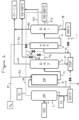
- FIG. 1 represents a device for implementing the process of the invention, for which two separate reactors (R1) and (R2) are represented respectively for the deparaffinization and dearomatization steps.
- FIG. 2 represents a device for implementing the process of the invention for which a single reactor is shown containing two distinct sections, (SR1) and (SR2) respectively for the deparaffinization and dearomatization stages, a cavity (30) separating these said sections.
- FIG. 3 represents the soft cracking and hydrotreatment sections contained in the dewaxing reactor R1 or SR1 in the figures 1 And 2 .
- a gas oil feed (GO) from all crude oil refining processes is introduced via line (10) into the separator allowing fractional distillation DF referenced (1) where it is separated into two cuts, one cut light (CI) evacuated from DF via pipe (12) and a heavy cut CL evacuated from DF via pipe (11).
- This heavy cut CL is sent to the dewaxing reactor R1 referenced (2) supplied in parallel by hydrogen arriving via pipes (31), then (32). All of the dewaxed effluent is directed through line (14) into a DA2 atmospheric distillation unit referenced (5). Two, three or four effluents are distilled depending on the recovery choice considered, only the deparaffinized CDP cut evacuated through line (15) is sent to the dearomatization step.
- the CDP cut evacuated by pipe (15) is sent by pipe (16) into the reactor R2 referenced (3) supplied in parallel with hydrogen from pipe (31) via pipe (33).
- the light cut recovered by the pipe (12) at the outlet of the DF separator (1) can be introduced in whole or in part via the pipe (24) into the CDP effluent before its entry into the reactor R2 (3).
- the cuts (C5-150) at the outlet of the distillations DA1 and DA2 can be advantageously mixed as well as the cuts (150-300) with all or part of the light cut CI in the line (12) then at the outlet of the DA1 distillation (4).
- the heavy cut CL leaving the separator DF (11) is only partially sent to the reactor R1 (2), part of said cut sent via the pipe (20) being mixed with the effluent deparaffinized CDP.
- part of the 300°C+ cut at the outlet of the DA1 distillation (4) is recycled via the pipe (28) in pipe (16) directing the CDP effluent into reactor R2 (3).
- FIG 2 differentiates itself from the figure 1 in that a single reactor (5) is represented for the dewaxing and dearomatization steps containing two sections, a dewaxing section SR1 referenced (2) and a dearomatization section SR2 referenced (3) these two sections being separated by a cavity (30).
- a diesel feed (GO) from all crude oil refining processes is introduced via line (10) into the DF separator referenced (1) where it is separated into two cuts, a light cut (CI) evacuated from DF (1) via pipe (12) and a heavy CL cut evacuated from DF (1) via pipe (11).
- the heavy cut CL is sent to the SR1 section (2) of the reactor (5) supplied in parallel by hydrogen arriving via the pipes (31), then (32) to be dewaxed there.
- the entire deparaffinized section is sent to section SR2 (3), possibly after being mixed in the cavity (30) separating the two sections with additional hydrogen arriving via line (33).
- This injection of hydrogen is useful for the dearomatization reaction but also has the function of adjusting the inlet temperature of the dewaxed charge or cut in the SR2 section (3) by quenching (or quench) allowing the temperature to be lowered. at the entrance to section SR2 (3).
- part of the 300°C+ cut leaving the DA1 distillation (4) is recycled via line (28) in the cavity (30) of the reactor (5) to be dearomatized again in the SR2 section of said reactor (5).
- FIG. 3 represents a section of the deparaffinization reactor (2) of the figure 1 or from the dewaxing section SR1(2) of the reactor (5).
- This section shows the layered distribution of the dewaxing (S1) and hydrotreatment (S2) catalysts.
- S1 is chosen from soft cracking hydrodewaxing catalysts, based on silicalite supporting nickel and possibly tungsten such as KF1102 marketed by the company ALBEMARLE.
- S2 is a classic hydrotreatment catalyst based on alumina supporting a metallic couple chosen from the couples cobalt/molybdenum, nickel/tungsten, cobalt/tungsten and nickel/molybdenum.
- S2 may be KF647 also sold by ALBEMARLE.
- the first and third layers are filled with dewaxing catalyst S1 and constitute the largest volumes (31% and 46% volume).
- the second and fourth layers are only filled with S2, each occupying a volume of 11.5%.
- the heavy cut (CL) to be deparaffinized is introduced into the reactor (2) of the figure 1 by the pipe (13), the hydrogen is injected through line (32) and the dewaxed effluent is recovered through line (14).
- the present example describes the preparation of a deparaffinized and dearomatized cut according to the invention, with an initial boiling temperature greater than 300°C and whose pour point is less than -30°C.
- the reaction temperature in the dewaxing reactor is 305 °C under a pressure of 30 barg, with a defined Volume Hourly Speed (VVH) corresponding to the ratio of feed volume flow rate (m3/h) to catalyst volume (m3/ h) 1h -1 and a hydrogen coverage of 250 NI (NL: normal liter) of hydrogen per liter of hydrocarbon feed.
- VVH Volume Hourly Speed
- the temperature is 245 °C, under a pressure of 160 barg, a hydrogen coverage of 250 NI of hydrogen per liter of hydrocarbon feed and a vvh of 0.4 h -1 .
- Table 1 The characteristics of the products from the start to the end of the reaction chain are given in Table 1 below.
- hydrocarbon fluids devoid of aromatics and all types of pollutants, usable as solvent with a distillation cut greater than 300°C and whose pour point is equal at -40°C.
- the quantity of naphthenes is much greater than 40% by weight in these hydrocarbons, the quantity of mononaphthenes being much greater than 20% by weight.
- Said pollutants correspond in particular to olefins, sulfur compounds and nitrogen compounds.
- the present example compares the characteristics of the products obtained in Example 1 referenced X with those of the products obtained from predominantly isomerizing hydrodewaxing of gas oil cuts or a hydrocracked and hydrodearomatized gas oil. These products from the prior art are referenced respectively T1 and T2.
- dewaxing makes it possible to reduce the pour point of the boiling point cut above 300°C to -40°C.
- the mononaphthenes content is very different, for X this being greater than 20% and even greater than 30% by weight while it remains much less than 20% by weight for T1.
- the reduction in the aniline point for the X cut indicates an improvement in the solvent power.
Landscapes
- Chemical & Material Sciences (AREA)
- Oil, Petroleum & Natural Gas (AREA)
- Engineering & Computer Science (AREA)
- Organic Chemistry (AREA)
- Chemical Kinetics & Catalysis (AREA)
- General Chemical & Material Sciences (AREA)
- Materials Engineering (AREA)
- Crystallography & Structural Chemistry (AREA)
- Inorganic Chemistry (AREA)
- Life Sciences & Earth Sciences (AREA)
- Wood Science & Technology (AREA)
- Production Of Liquid Hydrocarbon Mixture For Refining Petroleum (AREA)
Description
- La présente invention a pour objet un procédé d'obtention de solvants hydrocarbonés dépourvus de composés aromatiques et de soufre, de température d'ébullition supérieure ou égale à 300°C et de température d'ébullition finale inférieure ou égale à 500°C et dont le point d'écoulement est fortement abaissé jusqu'à - 40°C et moins. Ce procédé est particulièrement adapté au traitement de coupes gazoles obtenues par distillation et raffinage du pétrole brut. La présente invention concerne également les produits obtenus par le procédé et enfin l'application comme solvant des dits produits, notamment dans des environnements froids nécessitant un point d'écoulement très bas. Ces solvants sont utilisables comme fluides de forage, lubrifiants pour l'industrie y compris automobile, le travail des métaux, comme entrant dans la composition de produits phytosanitaires, des encres et des huiles d'extension pour les mastics et les joints, et comme abaisseurs de viscosité pour formulations à base de résine et de pâtes à base de polychlorure de vinyle (PVC).
- La nature chimique et la composition des fluides connus de l'homme du métier varient considérablement selon l'application envisagée et la matière d'origine des produits. Ainsi, certains sont d'origine pétrolière, d'autres sont issus de la chimie par polymérisation et/ou oligomérisation d'oléfines. Pour les produits d'origine pétrolière-, l'intervalle de distillation mesuré par l'ASTM D-86 ou ASTM D 2887 (choix selon le point initial ou final d'ébullition demandé en dessous de 270 °C ou au-dessus ou 400°C), le point d'écoulement mesuré par l'ASTM D 5950 (en référence à l'ASTM D97 3-points), la viscosité, la densité, les teneurs en soufre et en aromatiques, la densité, le point d'aniline mesuré par ASTM D-611, le mode de production de ces hydrocarbures, notamment la nature de la matière première distillée en coupes, et le point éclair constituent des caractéristiques importantes qui permettent de les distinguer et d'adapter ces produits aux différentes applications envisagées.
- Ces fluides hydrocarbonés ont souvent des gammes de points d'ébullition étroites entre le Point initial d'ébullition (IBP) et le Point final d'ébullition (FBP). Ces gammes sont choisies en fonction de l'application envisagée. L'étroitesse de celles-ci permet de disposer d'un point d'inflammation et/ou point éclair précis, paramètres importants pour des raisons de sécurité. Une gamme de coupe étroite permet en outre d'obtenir une viscosité mieux définie, une stabilité améliorée de celle-ci et des caractéristiques d'évaporation adaptées aux applications nécessitant une étape de séchage de durée contrôlée: elle favorise également l'obtention de coupes hydrocarbonées de tension de surface mieux définie, dont le point d'aniline et le pouvoir solvant sont plus précis. Cependant ce ne sont pas toujours les seules à prendre en compte, d'autres pouvant être prioritaires selon les applications visées.
- Pour être appliqués comme solvants dans différentes applications, ces fluides doivent être purifiés. La purification consiste typiquement en étapes d'hydrodésulfuration (et/ou hydrocraquage) et/ou d'hydrogénation pour réduire la teneur en soufre, la teneur en azote et/ou éliminer les hydrocarbures aromatiques, les oléfines et/ou cycles non saturés en les transformant en naphtènes. Les fluides hydrocarbonés ainsi purifiés sont majoritairement aliphatiques, ils contiennent des paraffines normales, des isoparaffines et des naphtènes. Pour ce type de fluide déaromatisé, le produit hydrocarboné qui a été désulfuré et/ou déazoté, puis fractionné, peut être hydrogéné pour saturer la totalité des hydrocarbures aromatiques qui sont présents. L'hydrogénation peut aussi être réalisée avant le fractionnement final.
- Les utilisateurs ont d'abord recherché essentiellement des fluides hydrocarbonés contenant de faibles concentrations en hydrocarbures aromatiques et des teneurs en soufre extrêmement faibles, dont les coupes ont des points initiaux d'ébullition plus élevés pour tenir compte des conditions environnementales ou de sécurité.
- Il est possible de traiter des gazoles issus de distillation directe dont le point final d'ébullition (FBP) est de 320°C pour obtenir des produits déaromatisés de point d'écoulement inférieur ou égal à 0°C. Le traitement de coupes de distillation de points finaux d'ébullition plus élevés, par exemple supérieurs à 350°C est tout aussi facile mais ne permet pas d'atteindre des points d'écoulement suffisamment bas dans la coupe lourde supérieure à 330°C après déaromatisation. En outre, la teneur en hydrocarbures aromatiques, notamment en polyaromatiques, est plus élevée. La présence de tels composés dans les hydrocarbures a des effets nocifs sur les catalyseurs d'hydrogénation dont la durée de vie est raccourcie et la performance limitée. Parfois, un traitement complémentaire d'hydrogénation est nécessaire pour diminuer encore la teneur en soufre de ces produits. Ainsi, le traitement de ces coupes grève notablement l'économie des procédés d'hydrogénation en augmentant considérablement la consommation d'hydrogène et les coûts de renouvellement du catalyseur qui se désactive rapidement.
- Maintenant, ces fluides hydrocarbonés doivent en outre présenter un bon compromis entre une viscosité élevée et de bonnes propriétés à froid, c'est-à-dire un point d'écoulement très bas, par exemple inférieur à -25°C et même inférieur à -30°C, un pouvoir solvant élevé, notamment pour l'application encre d'imprimerie nécessitant la dissolution de résines, mais aussi des composés visqueux ou solides entrant dans la composition des fluides de forage. Ces fluides hydrocarbonés utilisés comme huiles d'extension pour la fabrication des mastics à base de silicone doivent également présenter une bonne compatibilité avec les polymères siliconés et aussi le pouvoir d'abaisser la viscosité de certains polymères comme les PVC lorsqu'ils sont utilisés dans la fabrication des pâtes PVC ou Plastisols. Ces fluides hydrocarbonés entrant également dans la composition de produits phytosanitaires doivent de même présenter une viscosité et un degré de pureté compatibles avec les contraintes de toxicité et de phytotoxicité qu'implique cet usage.
-
US 2003 211949 A1 traite d'un fluide ayant un point d'écoulement égal à -40 °C.US 6517704 B1 traite d'un procédé d'obtention de solvants hydrocarbonés comprenant une étape de déparaffinage et une étape d'hydrodéaromatisation. - Il est également connu d'obtenir ces fluides à partir de composés issus de la distillation sous vide, notamment de gazoles sous vide ou vapocraqués qui peuvent alors être soumis à d'autres procédés comme le craquage catalytique couplé à une hydrogénation (hydrodésulfuration, hydrodéaromatisation) comme il est décrit dans le brevet
EP1447437 ou encore par hydrocraquage couplé à une hydrogénation, tels que décrits dans les brevetsWO03/074634 WO03/074635 - Cependant, les exigences en nouveaux fluides moins toxiques ou moins volatils de viscosité modérément élevée a conduit la demanderesse à utiliser comme fluides des hydrocarbures déparaffinés pour ses applications solvants comme il est décrit dans la demande de brevet
WO2010/103245 . Ces fluides sont obtenus à partir d'unités d'hydrodéparaffinage de différentes coupes gazoles issues d'autres unités de raffinage et de les distiller pour en faire des fluides hydrodéparaffinés aux intervalles de coupe appropriés, éventuellement après leur avoir fait subir des traitements de purification en vue de l'élimination du soufre et des hydrocarbures aromatiques. Ces fluides hydrodéparaffinés doivent satisfaire les mêmes caractéristiques de pureté que ceux requis pour les produits issus du pétrole brut comme la teneur en soufre mesurée par ASTM D5453 inférieure à 10 ppm, et une faible concentration en composés aromatiques, bien moins que 300 ppm. En outre ses caractéristiques sont identiques sinon meilleures que celles des produits issus du pétrole. Ces produits présentent un point final d'ébullition (FBP) supérieur à 300°C. - Cependant, tous les critères ne sont pas satisfaits sur toutes les coupes et en particulier sur les coupes de température initiale d'ébullition (IBP) supérieure à 300°C. En effet, bien que satisfaisant aux caractéristiques de teneur en soufre, de point éclair, d'aromatiques et de point d'aniline, ces coupes présentent un point d'écoulement très élevé souvent supérieur à -10°C, et même à 0°C ce qui les rend inutilisables dans un environnement froid à des températures inférieures à -25°C, et même inférieures à - 30°C. Ces coupes sont particulièrement recherchées pour les applications forage, encres et dans les matériaux type mastic.
- Pour résoudre ce problème, la Demanderesse a décidé de mettre en oeuvre un procédé d'hydrodéparaffinage particulier consistant à améliorer le point d'écoulement de des coupes de température d'ébullition initiale (IBP) supérieure ou égale à 300°C déterminée par l'ASTM D 86, indépendamment des autres coupes.
- Parmi les procédés d'hydrodéparaffinage, il existe deux procédés l'un favorisant la transformation des paraffines en isoparaffines par un procédé très isomérisant avec très peu de craquage des paraffines normales et l'autre basé sur le craquage doux des hydrocarbures traités, en particulier des paraffines normales.
- Le procédé d'hydrodéparaffinage favorisant l'isomérisation des oléfines se fait en présence d'un catalyseur d'isomérisation à base de zéolithe, par exemple une ZSM5 supportant des métaux de transition ou une ZSM48 supportant des métaux de type platine/palladium à une température variant de 200 à 500°C sous une pression d'hydrogène variant de 25 à 200 bars. Le traitement d'hydrofinissage est obtenu également sous pression d'hydrogène en présence d'un catalyseur sur base d'oxydes métalliques supportant du nickel, du molybdène, du cobalt, du palladium, du tungstène et des couples de ces métaux.
- Ces procédés d'hydrodéparaffinage très poussés sont utilisés pour la préparation de Diesel ou d'huiles hydrodéparaffinées à partir de coupes hydrocarbonées lourdes issues de l'unité de craquage catalytique des distillats sous-vide (craquage catalytique fluidisé (FCC (Fluid Catalytic Cracking)), telles que les coupes d'huiles légères de recyclage (LCO (Light Cycle Oil) ou de résidus du pétrole (slurry) ou encore de gazoles hydrocraqués permettant d'abaisser les points d'écoulement, sans pour autant atteindre des points d'écoulement inférieurs à -25°C, notamment sur les coupes au-delà de 300°C comme ceux décrits par exemple dans les demandes de brevets et brevets
WO2009/154324 ,WO2009/011479 ,EP665283 US6517704 ou encoreUS6340430 . On notera que ces traitements sont réalisés sur des coupes larges d'intervalles de coupe correspondant aux grades huiles et Diesel classiques, désirés. On obtient des coupes hydrocarbonées dites naphténiques mais dont la teneur en aromatiques est supérieure à 0,1% en poids, voire supérieure à 10% en poids (selon la méthode analytique IP391 : détermination par HPLC). Le traitement dit « d'hydrofinissage » utilisé après l'hydrodéparaffinage ne permet pas de convertir ces aromatiques en naphtènes. Dans ces procédés, l'hydrodéparaffinage « isomérisant » en présence de catalyseurs à base de platine/palladium sur support zéolithique/alumine est préféré à l'hydrodéparaffinage avec craquage. - Le procédé d'hydrodéparaffinage favorisant le craquage doux des paraffines normales à chaînes longues présentes dans la charge, est décrit dans les brevets
US4781906 ,US4842717 etUS5997727 . Il vise l'abaissement comme l'autre procédé, du point d'écoulement des gazoles par traitement de la totalité de la coupe gazole en présence d'un catalyseur à base de silicalites supportant éventuellement du nickel et/ou un couple nickel/tungstène sous hydrogène à une température variant de 350 à 450°C et sous une pression de 1 à 80 bars. Ce procédé a été en particulier appliqué sur une coupe gazole de température d'ébullition supérieure à 300°C mais pour un intervalle de coupe excédent 100°C et l'abaissement du point d'écoulement n'a pas permis d'atteindre une température inférieure ou égale à -25°C, le point d'écoulement avoisinant seulement 0°C. - La présente invention vise l'abaissement du point d'écoulement à une température inférieure ou égale à 40°C, pour les solvants issus de coupes gazoles (GO) de point d'ébullition initial supérieur ou égal à 300°C et de température d'ébullition finale inférieure ou égale à 500 °C, déterminée selon la norme ASTM D 86 par la mise en oeuvre d'un procédé permettant de façon intégrée de produire des solvants déaromatisés de température d'ébullition supérieure à 300°C, de moins de 100°C d'intervalle de coupe et contenant moins de 500 ppm d'aromatiques, désulfurés à moins de 10 ppm de soufre et dont le pouvoir solvant mesuré par son point d'aniline est amélioré. L'invention vise également l'intégration du dit procédé dans un procédé de préparation de toutes les coupes utilisables comme solvant, de température d'ébullition comprise entre 200 et 500°C et d'intervalle de coupe inférieur à 100°C.
- Dans la présente description de l'invention, les températures d'ébullition, points initiaux et finaux de distillation des coupes, sont mesurées selon la norme ASTM D 86.
- La présente invention a donc pour objet un procédé d'obtention de solvants hydrocarbonés de teneur en soufre inférieure à 10 ppm, de teneur en aromatiques inférieure à 500 ppm, de température d'ébullition initiale supérieure ou égale à 300°C et de température d'ébullition finale inférieure ou égale à 500°C, déterminées selon la norme ASTM D86, pour un intervalle de coupe d'au plus 100°C, et de point d'écoulement inférieur à 40°C selon la norme ASTM D5950, le procédé étant selon la revendication 1
- On entend par coupe 300°C+, les coupes distillant au-delà de 300°C selon la norme ASTM D 86.
- Un tel procédé présente l'avantage de préparer des coupes hydrocarbonées lourdes de températures d'ébullition initiales supérieures à 300°C appelées coupes 300°C+, mais aussi de préparer concomitamment d'autres coupes de températures d'ébullition initiales inférieures à 300°C répondant aux spécifications des solvants hydrocarbonés sans aromatiques et sans soufre. Ce résultat est obtenu en intégrant des procédés connus dans un enchaînement nouveau permettant la séparation et le mélange des flux avant et après traitement.
- On entend par charge constituée par une coupe gazole obtenue par tous procédés de raffinage, en particulier une coupe choisie parmi les gazoles de distillation atmosphérique, les gazoles de distillation sous vide, les gazoles hydrocraqués, les gazoles de craquage catalytique, les gazoles de viscoréduction, les gazoles de cokage, les gazoles issus de gaz de gisement, les gazoles désasphaltés, les gazoles issus de l'hydrotraitement des coupes lourdes (Résidu Atmosphérique et gazole de distillation sous vide ou VGO), les gazoles de teneur en soufre supérieure à 15 ppm étant nécessairement désulfurés par hydrotraitement et/ou hydrocraquage avant traitement selon le procédé de l'invention. On ne sortirait pas du cadre de l'invention si cette charge était issue de plusieurs coupes gazoles référencés dans la liste ci-dessus.
- La coupe hydrocarbonée de température d'ébullition supérieure ou égale à 300°C est obtenue par séparation de la coupe gazole en deux coupes, une coupe légère (CI) de température finale d'ébullition inférieure à 300°C et au moins une coupe lourde (CL) de température initiale d'ébullition supérieure ou égale à 300°C, chaque coupe présentant un intervalle de température d'ébullition entre 300°C et 500°C et un intervalle de distillation de préférence inférieur à 85°C.
- L'étape de déparaffinage traitant la dite coupe lourde (CL) comprend au moins une première section de craquage doux en présence d'un catalyseur à base de silicalite, choisi parmi les silicalites de rapport silice/alumine supérieur à 200 supérieur à 150, comprenant de 0 à 10 % en poids d'au moins un métal du groupe VIII et éventuellement de 0 à 10% en poids d'un métal du groupe VI, et une deuxième section d'hydrogénation des oléfines en présence d'un catalyseur qui est une alumine supportant un couple métallique choisi parmi les couples cobalt/molybdène, nickel/tungstène, cobalt/tungstène et nickel/molybdène.
- Afin de ne pas favoriser le cokage de la charge et des effluents produits, ni même l'isomérisation des oléfines formées, l'étape de déparaffinage comprendra au moins deux sections de craquage doux alternées avec deux sections d'hydrogénation des oléfines formées au cours des dits craquages, le catalyseur de déparaffinage étant choisi parmi les silicalites de rapport silice/alumine supérieur à 200, ces silicalites supportant du nickel seul ou un couple nickel/tungstène et le catalyseur d'hydrogénation d'oléfines étant une alumine supportant un couple métallique choisi parmi les couples cobalt/molybdène, nickel/tungstène, cobalt/tungstène et nickel/molybdène. La première section de craquage permet de craquer les produits sans provoquer de formation de coke, la section d'hydrogénation permettant de saturer des oléfines produites, sans réaction secondaire d'isomérisation, la seconde section de craquage permet de continuer le craquage tandis que la dernière section d'hydrogénation est une section de finition pour la saturation des oléfines.
- L'étape de déparaffinage est réalisée sous pression d'hydrogène, à une température variant de 150 à 450°C sous une pression totale variant de 10 à 400 bars, de préférence à une température variant de 280 à 380°C et une pression variant de 20 à 200 bars.
- L'effluent déparaffiné obtenu à l'étape de déparaffinage est envoyé à l'étape de séparation supplémentaire placée avant l'étape d'hydrodéaromatisation. Cet effluent déparaffiné est séparé en au moins deux effluents, une coupe hydrocarbonée de C1 à C4 (hydrocarbures comprenant de 1 à 4 carbones), et une coupe déparaffinée (ou CDP) dont au moins une partie distille au-dessus de 300°C et présente un point d'écoulement inférieur ou égal à -40°C. On ne sortirait pas du cadre de l'invention, si les coupes séparées étaient plus nombreuses et ne correspondaient pas exactement aux coupes spécifiées ci-dessous.
- L'effluent déparaffiné est séparé en deux coupes, trois coupes ou quatre coupes déparaffinées ;
- une coupe hydrocarbonée de C1 à C4 et une coupe hydrocarbonée de plus de 5 atomes de carbone (ou C5+),
- ou une coupe hydrocarbonée de C1 à C4 et deux coupes hydrocarbonées, l'une distillant de C5 à 150°C (ou C5-150 correspondant à une coupe essence) et l'autre distillant au-delà de 150°C (ou 150°C+),
- ou une coupe hydrocarbonée de C1 à C4 et trois coupes hydrocarbonées, la première distillant de C5 à 150°C (ou C5-150), la seconde distillant de 150 à 300°C (ou 150-300 correspondant à une coupe de gazole léger) et la troisième distillant au-delà de 300°C (ou 300°C+),
- En ce qui concerne la coupe 300°C+, il peut s'agir d'une ou plusieurs coupes distillant au-delà de 300°C (ou 300°C+),
- En sortie de l'étape de séparation supplémentaire, la coupe déparaffinée de température d'ébullition initiale la plus élevée issue de l'effluent déparaffiné est envoyée à l'étape d'hydrodéaromatisation, celle-ci comprenant une ou plusieurs sections d'hydrodéaromatisation.
- Par exemple, si l'effluent déparaffiné est séparé en deux coupes seulement, la coupe hydrocarbonée de plus de 5 atomes de carbone (ou C5+) est envoyée à l'étape d'hydrodéaromatisation. Si l'effluent déparaffiné est séparé en trois coupes, la coupe distillant au-delà de 150°C (ou 150°C+) est envoyée à l'étape d'hydrodéaromatisation. Enfin, si l'effluent déparaffiné est séparé en quatre coupes, c'est la coupe distillant au-delà de 300°C (ou 300°C+) qui est envoyée à l'étape d'hydrodéaromatisation. Eventuellement, la coupe légère (Cl) issue de la séparation de la coupe gazole en deux coupes est mélangée en tout ou partie à la coupe déparaffinée envoyée à l'étape d'hydrodéaromatisation.
- Cependant, dans une variante du dit procédé, les coupes (C5-150) et (150-300) pourraient être déaromatisées dans l'unité d'hydroaromatisation seules ou en mélange avec tout ou partie des autres coupes séparées dans la dite étape de séparation supplémentaire.
- Dans une variante du procédé selon l'invention, la coupe lourde (CL) issue de la séparation de la coupe gazole en au moins deux coupes peut être envoyée pour une partie au moins à l'étape de déparaffinage, l'autre partie étant mélangée à la coupe déparaffinée récupérée à la sortie de l'étape de séparation de l'effluent déparaffiné et envoyée à l'étape d'hydrodéaromatisation. Cette variante permet notamment d'ajuster la température du point d'écoulement de la dite coupe. De préférence, la totalité de la coupe lourde (CL) est envoyée à l'étape de déparaffinage.
- En sortie de la dernière étape de distillation atmosphérique, la coupe 300°C+ de point d'écoulement inférieur à -40°C est récupérée en totalité pour les applications envisagées ou au moins partiellement, une partie au moins pouvant être recyclée dans la coupe déparaffinée envoyée à l'étape d'hydrodéaromatisation, ce recycle permettant avantageusement de diminuer encore la teneur en aromatiques de cette coupe.
- Dans un mode de réalisation du procédé de l'invention, les étapes de déparaffinage et hydrodéaromatisation sont réalisées dans une même capacité ou dans des capacités différentes. De préférence, ces étapes sont conduites à la même pression variant de 60 à 200 bars sous atmosphère d'hydrogène, à une température variant de 150 à 450°C, de préférence variant de 280 à 380°C pour l'étape de déparaffinage et à une température variant de 80 à 250°C pour l'étape d'hydrodéaromatisation, la température de l'effluent déparaffiné étant ajustée avant l'étape d'hydrodéaromatisation par injection d'au moins un composé liquide ou gazeux de température inférieure d'au moins 50°C à celle de l'effluent déparaffiné.
- Pour cet ajustement de la température, le composé liquide ou gazeux est choisi parmi l'hydrogène, la coupe légère (Cl) issue de température d'ébullition inférieure à 300°C et la coupe 300°C+ de point d'écoulement inférieur à -25°C récupérée après distillation des effluents déparaffinés, éventuellement désulfurés, et déaromatisés.
- Le dispositif de mise en oeuvre du procédé comprend :
- une unité de séparation (DF) en communication avec un réacteur de déparaffinage (R1) ;
- un réacteur de déparaffinage (R1) comportant au moins deux lits catalytiques pour la section de craquage doux (S1) et pour la section d'hydrogénation des oléfines (S2), ledit réacteur de déparaffinage étant alimenté par une coupe hydrocarbonée de température d'ébullition supérieure à 300°C (ou 300°C+) issue de l'unité de séparation (DF) en deux coupes 150°-300°C (ou 150-300) et 300°C+ par distillation d'une coupe gazole issue de tous procédés de raffinage du pétrole brut ;
- au moins un réacteur d'hydrodéaromatisation (R2) en communication avec d'une part le réacteur de déparaffinage (R1) et d'autre part au moins une tour de distillation atmosphérique (DA1),
- au moins une tour de distillation atmosphérique (DA1).
- Dans un mode préféré, la coupe 300°C+ est issue d'une capacité de séparation (DF) disposée en amont du réacteur de déparaffinage (R1) séparant une coupe gazole issue de tous procédés de raffinage du pétrole brut, en deux coupes 150°-300°C (ou 150-300) et 300°C+.
- Dans un mode préféré, le dispositif de mise en oeuvre du procédé selon l'invention comprend une unité de séparation en deux coupes ou plus (DA2) disposée sur la conduite de sortie des effluents issus du réacteur de déparaffinage (R1).
- Par exemple, l'effluent déparaffiné peut être distillé dans l'unité de distillation DA2 en deux coupes, trois coupes ou quatre coupes déparaffinées ;
- une coupe hydrocarbonée de C1 à C4 et une coupe hydrocarbonée de plus de 5 atomes de carbone (ou C5+),
- ou une coupe hydrocarbonée de C1 à C4 et deux coupes hydrocarbonées, l'une distillant de C5 à 150°C (ou C5-150) et l'autre distillant au-delà de 150°C (ou 150°C+)
- ou une coupe hydrocarbonée de C1 à C4 et trois coupes hydrocarbonées, la première distillant de C5 à 150°C (ou C5-150), la seconde distillant de 150 à 300°C (ou 150-300) et la troisième distillant au-delà de 300°C (ou 300°C+).
- Dans un mode particulier de l'invention, les réacteurs de déparaffinage et d'hydrodéaromatisation constituent un seul même réacteur, les lits catalytiques étant répartis en deux sections, la section de déparaffinage (SR1) et la section de déaromatisation (SR2), ces deux sections étant séparées par une cavité (30) permettant le mélange de l'efffluent déparaffiné avec les composés liquides ou gazeux destinés à ajuster la température des effluents entrant dans la section de déaromatisation. Cette cavité (30) peut être vide ou remplie en tout ou partie par des matériaux inertes favorisant le mélange des gaz et des liquides.
- Ces effluents sont choisis de préférence parmi l'hydrogène et/ou le recycle des coupes CI et/ou 300°C+ de point d'écoulement inférieur à -25°C récupérés après la tour de distillation atmosphérique (DA1).
- Un second objet de l'invention est la coupe 300°C+ obtenue selon le procédé de l'invention, de point d'écoulement inférieur à -40°C de point initial d'ébullition supérieur à 300°C et de température finale d'ébullition inférieure ou égale à 500°C, d'intervalle de coupe inférieur à 100°C, de teneur en soufre inférieure à 10 ppm et de teneur en aromatiques inférieure à 500 ppm et qui contient plus de 30% en poids de composés naphténiques et moins de 5% en poids de normales paraffines. Les composés mononaphténiques représentent plus de 20% du poids des composés naphténiques.
- De préférence, cette coupe présente un intervalle de coupe inférieur ou égal à 85°C, de préférence une teneur en soufre inférieure à 5ppm et une teneur en aromatiques inférieure à 300 ppm, ces préférences pouvant être atteintes indépendamment les unes des autres ou en combinaison.
- Bien entendu par coupe 300°C+ récupérée on entend une ou plusieurs coupes 300°C+, de température d'ébullition comprises entre 300°C et 450°C et de largeur de coupe inférieure ou égale à 75°C, de préférence inférieure à 65°C.
- Ces ou cette coupe(s) 300°C+ comprennent moins de 35% en poids d'hydrocarbures ayant une longueur de chaîne supérieure à 22 atomes de carbone, et plus de 65% en poids d'hydrocarbures ayant une longueur de chaîne inférieure à 22 atomes de carbone.
- Dans un mode de réalisation, la coupe 300°C+ présente un point initial d'ébullition supérieur ou égal à 330°C.
- Dans un mode de réalisation, la coupe 300°C+ présente un pourcentage de naphtènes polycycliques inférieur à 20%, de préférence inférieur à 10%.
- Un troisième objet de l'invention est l'utilisation de la (ou des) coupe(s) 300°C+ comme solvant dans les applications phytosanitaires, encres et mastic ou encore comme fluide pour le travail des métaux. Ces applications nécessitent des points d'écoulements bas tout en présentant des qualités de pureté et de caractère non VOC (ou volatil organic compounds en français composés organiques volatiles) important pour des utilisations en milieux domestiques.
- Pour décrire l'invention de façon plus précise, des figures représentant les différentes formes de mise en oeuvre de l'invention sont données en appui à la présente description.
- La
figure 1 représente un dispositif de mise en oeuvre du procédé de l'invention, pour lequel deux réacteurs séparés (R1) et (R2) sont représentés respectivement pour les étapes de déparaffinage et de déaromatisatrion. - La
figure 2 représente un dispositif de mise en oeuvre du procédé de l'invention pour lequel un seul réacteur est représenté renfermant deux sections distinctes, (SR1) et (SR2) respectivement pour les étapes de déparaffinage et de déaromatisatrion, une cavité (30) séparant ces dites sections. - La
figure 3 représente les sections de craquage doux et d'hydrotraitement contenues dans le réacteur de déparaffinage R1 ou SR1 dans lesfigures 1 et2 . - Dans la
figure 1 , une charge de gazole (GO) issue de tous procédés de raffinage du pétrole brut est introduite par la conduite (10) dans le séparateur permettant une distillation fractionnée DF référencé (1) où elle est séparée en deux coupes, une coupe légère (CI) évacuée de DF par la conduite (12) et une coupe lourde CL évacuée de DF par la conduite (11). - Cette coupe lourde CL est envoyée dans le réacteur de déparaffinage R1 référencé (2) alimenté en parallèle par de l'hydrogène arrivant par les conduites (31), puis (32). La totalité de l'effluent déparaffiné est dirigée par la conduite (14) dans une unité de distillation atmosphérique DA2 référencée (5). Deux, trois ou quatre effluents sont distillés selon le choix de valorisation envisagé, seule la coupe déparaffinée CDP évacuée par la conduite (15) est envoyée à l'étape de déaromatisation.
- Par exemple, l'effluent déparaffiné peut être distillé dans l'unité de distillation DA2 en deux coupes, trois coupes ou quatre coupes déparaffinées ;
- une coupe hydrocarbonée de C1 à C4 encore appelée "fuel gas" évacuée par la conduite (21) et une coupe hydrocarbonée de plus de 5 atomes de carbone (ou C5+) évacuée par la conduite (15) vers le réacteur R2 de déaromatisation référencé (3),
- ou une coupe hydrocarbonée de C1 à C4 évacuée par la conduite (21) et deux coupes hydrocarbonées, l'une distillant de C5 à 150°C (ou C5-150) évacuée par la conduite (22) et l'autre distillant au-delà de 150°C (ou 150°C+) évacuée par la conduite (15) vers le réacteur R2 de déaromatisation référencé (3),
- ou une coupe hydrocarbonée de C1 à C4 évacuée par la conduite (21) et trois coupes hydrocarbonées, la première distillant de C5 à 150°C (ou C5-150) évacuée par la conduite (22), la seconde distillant de 150 à 300°C (ou 150-300) évacuée par la conduite (23) et la troisième distillant au-delà de 300°C (ou 300°C+ évacuée par la conduite (15) vers le réacteur R2 de déaromatisation référencé (3).
- La coupe CDP évacuée par la conduite (15) est envoyée par la conduite (16) dans le réacteur R2 référencé (3) alimenté parallèlement par de l'hydrogène issu de la conduite (31) via la conduite (33).
- L'effluent déparaffiné et déaromatisé est récupéré en sortie du réacteur R2 (3) par la conduite (17) et dirigé vers une unité de distillation DA1 référencée (4) pour y être distillé en au moins quatre coupes :
- la (ou les) coupes 300°C+ récupérées via la conduite (18),
- la coupe (150-300) évacuée par la conduite (27),
- la coupe (C5-150) évacuée par la conduite (26),
- et la coupe C1-C4 ou "fuel gas" évacuée par la conduite (25).
- Dans un certain mode de mise en oeuvre, la coupe légère récupérée par la conduite (12) en sortie du séparateur DF (1) peut être introduite en tout ou partie via la conduite (24) dans l'effluent CDP avant son entrée dans le réacteur R2 (3).
- En outre, les coupes (C5-150) en sortie des distillations DA1 et DA2 peuvent être avantageusement mélangées de même que les coupes (150-300) avec tout ou partie de la coupe légère CI dans la conduite (12) puis en sortie de la distillation DA1 (4).
- Dans certains modes préférés, la coupe lourde CL en sortie du séparateur DF (11) n'est envoyée que partiellement vers le réacteur R1 (2), une partie de la dite coupe envoyée par la conduite (20) étant mélangée avec l'effluent déparaffiné CDP.
- De même, si la teneur en aromatiques est trop élevée dans la coupe 300°C+ ou que la viscosité de l'effluent CDP est insuffisante, une partie de la coupe 300°C+ en sortie de la distillation DA1 (4) est recyclée via la conduite (28) dans la conduite (16) dirigeant l'effluent CDP dans le réacteur R2 (3).
- La
figure 2 se différencie de lafigure 1 en ce qu'un seul réacteur (5) est représenté pour les étapes de déparaffinage et de déaromatisation contenant deux sections, une de déparaffinage SR1 référencée (2) et une section de déaromatisation SR2 référencée (3) ces deux sections étant séparées par une cavité (30). Dans cette figure, une charge de gazole (GO) issue de tous procédés de raffinage du pétrole brut est introduite par la conduite (10) dans le séparateur DF référencé (1) où elle est séparée en deux coupes, une coupe légère (CI) évacuée de DF (1) par la conduite (12) et une coupe lourde CL évacuée de DF (1) par la conduite (11). - La coupe lourde CL est envoyée dans la section SR1 (2) du réacteur (5) alimenté en parallèle par de l'hydrogène arrivant par les conduites (31), puis (32) pour y être déparaffinée. Toute la coupe déparaffinée est envoyée vers la section SR2 (3), éventuellement après avoir été mélangée dans la cavité (30) séparant les deux sections avec de l'hydrogène complémentaire arrivant par la conduite (33). Cette injection d'hydrogène est utile à la réaction de déaromatisation mais a aussi pour fonction d'ajuster la température d'entrée de la charge ou coupe déparaffinée dans la section SR2 (3) par trempe (ou quench) permettant d'abaisser la température en entrée de la section SR2 (3).
- Dans un mode particulier de l'invention, il est également possible d'injecter tout ou partie de la coupe légère (Cl) via la conduite (24) dans la cavité (30) pour être déaromatisée comme la coupe lourde (CL) déparaffinée. La quantité d'hydrogène sera ajustée en conséquence ainsi que la température d'entrée dans la section SR2 (3).
- Comme dans la
figure 1 , l'effluent déparaffiné et déaromatisé est récupéré en sortie du réacteur (5) par la conduite (17) et dirigé vers une unité de distillation DA1 référencée (4) pour y être distillé en au moins quatre coupes : - la (ou les) coupes 300°C+ récupérées via la conduite (18),
- la coupe (150-300) évacuée par la conduite (27),
- la coupe (C5-150) évacuée par la conduite (26),
- et la coupe C1-C4 ou "fuel gas" évacuée par la conduite (25).
- De même, si la teneur en aromatiques est trop élevée dans la (ou les) coupe(s) 300°C+, une partie de la coupe 300°C+ en sortie de la distillation DA1 (4) est recyclée via la conduite (28) dans la cavité (30) du réacteur (5) pour y être une nouvelle fois déaromatisée dans la section SR2 du dit réacteur (5).
- La
figure 3 représente une coupe du réacteur de déparaffinage (2) de lafigure 1 ou de la section de déparaffinage SR1(2) du réacteur (5). Cette coupe présente la répartition en couches des catalyseurs de déparaffinage (S1) et d'hydrotraitement (S2). S1 est choisi parmi les catalyseurs d'hydrodéparaffinage à craquage doux, sur base silicalite supportant du nickel et éventuellement du tungstène comme le KF1102 commercialisé par la société ALBEMARLE. S2 est un catalyseur d'hydrotraitement classique sur base d'alumine supportant un couple métallique choisi parmi les couples cobalt/molybdène, nickel/tungstène, cobalt/tungstène et nickel/molybdène. S2 peut être du KF647 vendu également par ALBEMARLE. Dans un mode préféré de l'invention, la première et la troisième couches sont remplies de catalyseur S1 de déparaffinage et constituent les plus gros volumes (31% et 46% volume). Les deuxième et quatrième couches ne sont remplies que de S2 occupant chacune un volume de 11,5 %. Dans cettefigure 3 , la coupe lourde (CL) à déparaffiner est introduite dans le réacteur (2) de lafigure 1 par la conduite (13), l'hydrogène est injecté par la conduite (32) et l'effluent déparaffiné est récupéré par la conduite (14). - Les performances de la présente invention vont être maintenant illustrées dans la suite de la présente description, mais ces exemples ne viseront pas à en limiter la portée.
- Le présent exemple décrit la préparation d'une coupe déparaffinée et déaromatisée selon l'invention, de température initiale d'ébullition supérieure à 300°C et dont le point d'écoulement est inférieur à -30°C.
- On opère comme décrit dans la
figure 1 en utilisant dans le réacteur de déparaffinage (2) les catalyseurs décrits ci-dessus pour lafigure 3 . Dans le réacteur de déaromatisation, on utilise un catalyseur nickel sur alumine, la quantité de nickel étant supérieure à 10% en poids et la surface spécifique étant supérieure à 140mm2/g. - La température de réaction dans le réacteur de déparaffinage est de 305 °C sous une pression de 30 barg, avec une Vitesse Volume Horaire (VVH) définie correspondant au ratio débit de volume de charge (m3/h) sur volume de catalyseur (m3/h) de 1h-1 et une couverture d'hydrogène de 250 NI (NL : litre normal) d'hydrogène par litre de charge hydrocarbonée. Dans le réacteur de déaromatisation, la température est de 245 °C, sous une pression de 160 barg, une couverture d'hydrogène de 250 NI d'hydrogène par litre de charge hydrocarbonée et un vvh de 0,4 h-1. Les caractéristiques des produits depuis le début à la fin de la chaîne de réaction sont données dans le tableau 1 ci-après.
TABLEAU 1 Caractéristiques GO avant DF Coupe 300°C+ Avant R1 (2) Après DA2 Après R2 et DA1 % poids Aromatiques 17,5 9,8 13,8 127ppm % poids n-paraffines 21,5 27,7 6,3 4,5 % poids Isoparaffines 35 38,4 42,7 47,1 % poids Naphtènes totaux 25,8 24,1 34,4 48,3 % poids mononaphtenes 20,8 23,2 - 35,8 % poids oléfines ASTM D2710 (gBr2/100g échantillon) 0,52 0,35 0,7 <0,05 % poids Saturés<C9 <0,09 0 <0,1 <0,1 Viscosité à 40°C (mm2/s), ASTM D445 4,5 7,7 8,7 8,7 Soufre (ppm) ASTM D5453 2 2,4 3,9 <1 Azote (ppm) par chemiluminescence <0,5 <0,5 <0,5 <0,5 Coupe distillation (°C) ASTM D86 236-365 296,8- 369,3 327,9- 371,4 314-367,3 Point d'écoulement (°C) ASTM D5950 en référence à D97 (3-points) -4 + 12 -40 -40 Point d'aniline (°C) ASTM D-611 - - - 98,7 - On constate donc que par le procédé de l'invention, on obtient des fluides hydrocarbonés dépourvus d'aromatiques et de tous types de polluants, utilisables comme solvant, de coupe de distillation supérieure à 300°C et dont le point d'écoulement est égal à - 40 °C. On notera que la quantité en naphtènes est très supérieure à 40% en poids dans ces hydrocarbures, la quantité en mononaphtènes étant très supérieure à 20% en poids. Les dits polluants correspondent notamment aux oléfines, aux composés soufrés et aux composés azotés.
- Le présent exemple compare les caractéristiques des produits obtenus dans l'exemple 1 référencé X avec celles des produits obtenus à partir d'hydrodéparaffinage majoritairement isomérisant de coupes gazoles ou un gazole hydrocraqué et hydrodéaromatisé. Ces produits issus de l'art antérieur sont référencés respectivement T1 et T2.
- Les caractéristiques comparées sont données dans le tableau 2 ci-après.
TABLEAU 2 Caractéristiques X T1 T2 ppm en poids des aromatiques 127 264 70 % poids n-paraffines 4,5 0,1 16 % poids Isoparaffines 47,1 74,2 59,9 % poids Naphtènes totaux 48,3 24,8 24,1 % poids mononaphtenes 35,8 18,9 22,4 Soufre (ppm) par méthode UV <1 <1 <1 Viscosité à 40°C (mm2/s), ASTM D445 8,7 10,3 6,1 Coupe distillation (°C), ASTM D86 314-367 334-378 305-347 Point d'écoulement (°C), ASTM D5950 en référence à D97 (3-points) -40 -35 0 Point d'aniline (°C), ASTM D611 98,7 108 101 - On notera que le déparaffinage permet de diminuer le point d'écoulement de la coupe de point d'ébullition supérieure à 300°C à -40 °C. On notera que comparativement entre les coupes X et T1, la teneur en mononaphtènes est très différente, pour X celle-ci étant supérieur à 20% et même supérieure à 30% en poids tandis qu'elle reste très inférieure à 20% en poids pour T1. La réduction du point d'aniline pour la coupe X indique une amélioration du pouvoir solvant.
Claims (7)
- Procédé d'obtention de solvants hydrocarbonés de teneur en soufre inférieure à 10 ppm, de teneur en aromatiques inférieure à 500 ppm, de température d'ébullition initiale supérieure ou égale à 300°C et de température d'ébullition finale inférieure ou égale à 500°C, déterminées selon la norme ASTM D86, pour un intervalle de coupe d'au plus 100°C, et de point d'écoulement inférieur ou égal à -40°C selon la norme ASTM D5950 comprenant les étapes :- de déparaffinage (2) d'une coupe hydrocarbonée de température d'ébullition supérieure ou égale à 300°C issue de la distillation (DF) d'une coupe gazole en deux coupes, une coupe légère (CI) de température d'ébullition inférieure à 300°C et au moins une coupe lourde (CL) de température d'ébullition initiale et finale supérieures ou égales à 300°C,la coupe gazole étant choisie parmi les gazoles de distillation atmosphériques, les gazoles de distillation sous vide, les gazoles hydrocraqués, les gazoles de craquage catalytique, les gazoles de viscoréduction, les gazoles de cokage et les gazoles désasphaltés, les gazoles de teneur en soufre supérieure à 15 ppm étant désulfurés par hydrotraitement et/ou hydrocraquage, et récupération de tout ou partie de l'effluent déparaffiné (14), l'étape de déparaffinage comprenant au moins deux sections de craquage doux (S1) alternées avec deux sections d'hydrogénation (S2) des oléfines, les sections de craquage doux comprenant un catalyseur à base de silicalite choisi parmi les silicalites de rapport silice-alumine supérieur à 200, comprenant de 0 à 10% en poids d'au moins un métal du groupe VIII, et éventuellement de 0 à 10% en poids d'un métal du groupe VI, ces silicalites supportant du nickel seul ou un couple nickel/tungstène, les sections d'hydrogénation des oléfines comprenant un catalyseur qui est une alumine supportant un couple métallique choisi parmi les couples cobalt/molybdène, nickel/tungstène, cobalt/tungstène et nickel/molybdène,l'étape de déparaffinage étant obtenue sous pression d'hydrogène, à une température variant de 150 à 450°C sous une pression totale variant de 10 à 400 bars,- d'hydrodéaromatisation (3) de tout ou partie de l'effluent déparaffiné, en présence d'un catalyseur comprenant du nickel sur base alumine, à une pression variant de 60 à 200 bars et une température variant 80 et 250°C, le dit effluent déparaffiné étant préalablement désulfuré si sa teneur en soufre est supérieure à 15 ppm, et en cas d'hydrodéaromatisation partielle, l'effluent déparaffiné est envoyé dans une étape de séparation (DA2) avant d'atteindre l'étape d'hydrodéaromatisation, l'effluent déparaffiné étant séparé en au moins deux effluents qui sont une coupe hydrocarbonée de C1 à C4 (21) et au moins une coupe déparaffinée (15) dont une partie distillant à au moins 300°C présente un point d'écoulement inférieur ou égal à -40°C,- de récupération de la coupe déparaffinée, éventuellement désulfurée, et déaromatisée,- de distillation (DA1) de ladite coupe déparaffinée et déaromatisée pour la séparer en deux coupes, trois coupes ou quatre coupes déparaffinées ;- une coupe hydrocarbonée de C1 à C4 (21) et une coupe hydrocarbonée de plus de 5 atomes de carbone (15),- ou une coupe hydrocarbonée de C1 à C4 (21) et deux coupes hydrocarbonées, l'une distillant de C5 à 150°C (22) et l'autre distillant au-delà de 150°C (15),- ou une coupe hydrocarbonée de C1 à C4 (21) et trois coupes hydrocarbonées, la première distillant de C5 à 150°C (22), la seconde distillant de 150 à 300°C et la troisième distillant à partir de 300°C (15),- et enfin de récupération d'au moins une coupe distillant à une température d'au moins 300°C (300°C+) de point d'écoulement inférieur ou égal à -40°C utilisable comme solvant, cette coupe présentant un intervalle de distillation inférieur à 100°C.
- Procédé selon la revendication 1, caractérisé en ce que l'étape de déparaffinage est obtenue à une température variant de 280 à 380°C et une pression variant de 20 à 200 bars.
- Procédé selon l'une des revendications précédentes, caractérisé en ce que la coupe déparaffinée de température de distillation initiale la plus élevée issue de l'effluent déparaffiné est envoyée à l'étape d'hydrodéaromatisation, celle-ci comprenant une ou plusieurs sections d'hydrodéaromatisation.
- Procédé selon l'une des revendications précédentes, caractérisé en ce que la coupe 300°C+ de point d'écoulement inférieur ou égal à -40°C récupérée après la dernière étape de distillation atmosphérique est récupérée en totalité ou partiellement en recyclant (28) au moins une partie dans la coupe déparaffinée envoyée à l'étape d'hydrodéaromatisation.
- Procédé selon l'une des revendications 1 à 4, caractérisé en ce que les étapes de déparaffinage et d'hydrodéaromatisation sont réalisées dans un même réacteur, les lits catalytiques étant séparés par une cavité (30) permettant le mélange de l'effluent déparaffiné avec les composés liquides ou gazeux, hydrogène ou recycle des coupes Cl (24) et 300°C+ de point d'écoulement inférieur ou égal à -40°C récupérée (28) après la tour de distillation atmosphérique (DA1).
- Coupe (300°C+) de point d'écoulement inférieur ou égal à -40°C, de température initiale d'ébullition supérieure à 300°C et de température finale d'ébullition inférieure ou égale à 500°C, d'intervalle de coupe inférieur à 100°C, de teneur en soufre inférieure à 10 ppm et de teneur en aromatiques inférieure à 500 ppm obtenue par le procédé selon l'une des revendications 1 à 5 caractérisée en ce qu'elle contient plus de 30% en poids de composés naphténiques, et moins de 5% en poids de normales paraffines, les composés mononaphténiques représentant plus de 20% du poids des composés naphténiques.
- Utilisation de la coupe selon la revendication 6, comme solvant dans les applications phytosanitaires, encres et mastic ou encore comme fluide pour le travail des métaux.
Applications Claiming Priority (2)
| Application Number | Priority Date | Filing Date | Title |
|---|---|---|---|
| FR1261848A FR2999190B1 (fr) | 2012-12-10 | 2012-12-10 | Procede d'obtention de solvants hydrocarbones de temperature d'ebullition superieure a 300°c et de point d'ecoulement inferieur ou egal a -25°c |
| PCT/EP2013/075989 WO2014090757A1 (fr) | 2012-12-10 | 2013-12-09 | Procede d'obtention de solvants hydrocarbones de temperature d'ebullition superieure a 300°c et de point d'ecoulement inferieur ou egal a -25°c |
Publications (2)
| Publication Number | Publication Date |
|---|---|
| EP2928989A1 EP2928989A1 (fr) | 2015-10-14 |
| EP2928989B1 true EP2928989B1 (fr) | 2024-03-27 |
Family
ID=47714362
Family Applications (1)
| Application Number | Title | Priority Date | Filing Date |
|---|---|---|---|
| EP13802957.4A Active EP2928989B1 (fr) | 2012-12-10 | 2013-12-09 | Procédé d'obtention de solvants hydrocarbonés de température d'ébullition supérieure à 300 °c et de point d'écoulement inférieur ou égal à - 40 °c |
Country Status (15)
| Country | Link |
|---|---|
| US (2) | US10047305B2 (fr) |
| EP (1) | EP2928989B1 (fr) |
| JP (1) | JP6392774B2 (fr) |
| KR (1) | KR102325122B1 (fr) |
| CN (1) | CN104981534B (fr) |
| AR (1) | AR093879A1 (fr) |
| AU (1) | AU2013357462A1 (fr) |
| BR (1) | BR112015013609A2 (fr) |
| CA (1) | CA2894475C (fr) |
| EA (1) | EA201591109A1 (fr) |
| FI (1) | FI2928989T3 (fr) |
| FR (1) | FR2999190B1 (fr) |
| SG (1) | SG11201504521YA (fr) |
| TW (1) | TWI635172B (fr) |
| WO (1) | WO2014090757A1 (fr) |
Families Citing this family (31)
| Publication number | Priority date | Publication date | Assignee | Title |
|---|---|---|---|---|
| FR2999190B1 (fr) | 2012-12-10 | 2015-08-14 | Total Raffinage Marketing | Procede d'obtention de solvants hydrocarbones de temperature d'ebullition superieure a 300°c et de point d'ecoulement inferieur ou egal a -25°c |
| US10022700B2 (en) | 2014-12-12 | 2018-07-17 | Exxonmobil Research And Engineering Company | Organosilica materials and uses thereof |
| US10155826B2 (en) | 2014-12-12 | 2018-12-18 | Exxonmobil Research And Engineering Company | Olefin polymerization catalyst system comprising mesoporous organosilica support |
| WO2016094820A1 (fr) | 2014-12-12 | 2016-06-16 | Exxonmobil Research And Engineering Company | Adsorbant destiné à l'élimination des espèces hétéroatomes et utilisations |
| JP2018502704A (ja) | 2014-12-12 | 2018-02-01 | エクソンモービル リサーチ アンド エンジニアリング カンパニーExxon Research And Engineering Company | オルガノシリカ材料を使用するコーティング方法およびその使用 |
| CA2964409A1 (fr) * | 2014-12-12 | 2016-06-16 | Exxonmobil Research And Engineering Company | Procedes de separation de composes aromatiques d'huiles de base lubrifiantes |
| US10047304B2 (en) | 2014-12-12 | 2018-08-14 | Exxonmobil Research And Engineering Company | Aromatic hydrogenation catalysts and uses thereof |
| WO2016094803A1 (fr) | 2014-12-12 | 2016-06-16 | Exxonmobil Research And Engineering Company | Procédés de fabrication de membrane à l'aide de matériaux à base d'organosilice et leurs utilisations |
| US10207249B2 (en) | 2014-12-12 | 2019-02-19 | Exxonmobil Research And Engineering Company | Organosilica materials and uses thereof |
| WO2016094848A1 (fr) | 2014-12-12 | 2016-06-16 | Exxonmobil Chemical Patents Inc. | Matériaux organosiliciés destiné à être utilisés en tant qu'adsorbants pour l'élimination de composés oxygénés |
| US9956541B2 (en) | 2014-12-12 | 2018-05-01 | Exxonmobil Research And Engineering Company | Methods of separating aromatic compounds from lube base stocks |
| US10294312B2 (en) | 2014-12-12 | 2019-05-21 | Exxonmobil Research And Engineering Company | Olefin polymerization catalyst system comprising mesoporous organosilica support |
| EP3095839A1 (fr) | 2015-05-20 | 2016-11-23 | Total Marketing Services | Procédé pour la production de fluides hydrocarbonés biodégradables par hydrogénation |
| US10550335B2 (en) | 2015-12-28 | 2020-02-04 | Exxonmobil Research And Engineering Company | Fluxed deasphalter rock fuel oil blend component oils |
| US10808185B2 (en) | 2015-12-28 | 2020-10-20 | Exxonmobil Research And Engineering Company | Bright stock production from low severity resid deasphalting |
| US10590360B2 (en) | 2015-12-28 | 2020-03-17 | Exxonmobil Research And Engineering Company | Bright stock production from deasphalted oil |
| FR3050096B1 (fr) | 2016-04-15 | 2018-04-27 | Total Marketing Services | Composition d’huile phytosanitaire paraffinique |
| US10494579B2 (en) | 2016-04-26 | 2019-12-03 | Exxonmobil Research And Engineering Company | Naphthene-containing distillate stream compositions and uses thereof |
| EP3468712A1 (fr) | 2016-06-10 | 2019-04-17 | Exxonmobil Research And Engineering Company | Catalyseurs à base de polymères d'organosilice et leurs procédés de production |
| EP3468915A1 (fr) | 2016-06-10 | 2019-04-17 | Exxonmobil Research And Engineering Company | Matières à base d'organosilice, procédés de production et utilisations de ces dernières |
| CN118480380A (zh) | 2016-10-18 | 2024-08-13 | 马威特尔有限责任公司 | 一种燃料以及燃烧方法 |
| KR102327301B1 (ko) | 2016-10-18 | 2021-11-17 | 모에탈 엘엘씨 | 폴리싱된 터빈 연료 |
| EP3529336A4 (fr) | 2016-10-18 | 2020-04-15 | Mawetal LLC | Compositions de carburant à partir de pétroles de réservoirs étanches et d'huiles combustibles à haute teneur en soufre |
| EP3315587A1 (fr) * | 2016-10-27 | 2018-05-02 | Total Marketing Services | Utilisation de fluides d'hydrocarbure biodégradables pour le laminage à froid de l'aluminium |
| US10179839B2 (en) | 2016-11-18 | 2019-01-15 | Exxonmobil Research And Engineering Company | Sulfur terminated organosilica materials and uses thereof |
| EP3342842A1 (fr) | 2017-01-03 | 2018-07-04 | Total Marketing Services | Procédé de déparaffinage et désaromatisation d'hydrocarbure dans un bioréacteur à boues liquides |
| EP3388499A1 (fr) * | 2017-04-11 | 2018-10-17 | Hindustan Petroleum Corporation Ltd. | Procédé de préparation de solvants d'hydrocarbures désaromatisés |
| JP7146391B2 (ja) * | 2017-12-08 | 2022-10-04 | Eneos株式会社 | 冷凍機油及び冷凍機用作動流体組成物 |
| CN111511465B (zh) | 2017-12-21 | 2023-06-06 | 埃克森美孚科技工程公司 | 生产有机二氧化硅材料的方法及其用途 |
| FI127871B (en) | 2018-04-05 | 2019-04-15 | Neste Oyj | Hydrogenation process and equipment |
| AU2021448387A1 (en) * | 2021-06-03 | 2023-10-26 | Joe DANDACHLI | Systems and methods associated with a removable inlet shield |
Family Cites Families (19)
| Publication number | Priority date | Publication date | Assignee | Title |
|---|---|---|---|---|
| US4428825A (en) | 1981-05-26 | 1984-01-31 | Union Oil Company Of California | Catalytic hydrodewaxing process with added ammonia in the production of lubricating oils |
| US4720337A (en) * | 1984-12-24 | 1988-01-19 | Mobil Oil Corporation | Hydrodewaxing method with interstage separation of light products |
| LU86269A1 (fr) * | 1986-01-28 | 1987-09-03 | Labofina Sa | Procede pour enlever les cires des gasoils |
| US6569313B1 (en) | 1995-12-22 | 2003-05-27 | Exxonmobil Research And Engineering Company | Integrated lubricant upgrading process |
| US6517704B1 (en) * | 1998-09-29 | 2003-02-11 | Exxonmobil Research And Engineering Company | Integrated lubricant upgrading process |
| US6340430B1 (en) * | 1999-09-15 | 2002-01-22 | Uop Llc | Distillate dewaxing process |
| EP2439254A3 (fr) * | 2002-03-06 | 2012-06-20 | ExxonMobil Chemical Patents Inc. | Fluides d'hydrocarbures améliorés |
| EP1342774A1 (fr) | 2002-03-06 | 2003-09-10 | ExxonMobil Chemical Patents Inc. | Procédé pour la production de fluides hydrocarbures |
| KR101156370B1 (ko) | 2005-02-17 | 2012-06-13 | 에스케이에너지 주식회사 | 저방향족 및 초저유황 경유를 제조하는 방법 |
| KR101008266B1 (ko) | 2005-12-12 | 2011-01-13 | 네스테 오일 오와이제이 | 포화 탄화수소 성분의 제조방법 |
| WO2007105769A1 (fr) * | 2006-03-15 | 2007-09-20 | Nippon Oil Corporation | Huile de graissage de base, composition d'huile lubrifiante pour moteur a combustion interne et composition d'huile lubrifiante pour dispositif de transmission d'entrainement |
| FR2943070B1 (fr) * | 2009-03-12 | 2012-12-21 | Total Raffinage Marketing | Fluide hydrocarbone hydrodeparaffine utilise dans la fabrication de fluides industriels, agricoles ou a usage domestique |
| FR2943064B1 (fr) | 2009-03-12 | 2013-12-06 | Total Raffinage Marketing | Diluant hydrocarbone a bas taux de cov pour materiaux de construction |
| WO2011061575A1 (fr) * | 2009-11-20 | 2011-05-26 | Total Raffinage Marketing | Procédé pour la production de fluides hydrocarbures ayant une faible teneur en aromatiques |
| WO2011061576A1 (fr) * | 2009-11-20 | 2011-05-26 | Total Raffinage Marketing | Procédé pour la production de fluides hydrocarbures ayant une faible teneur en aromatiques |
| CA2797970C (fr) * | 2010-05-14 | 2016-11-01 | Exxonmobil Research And Engineering Company | Procede de fabrication de gazole a teneur reduite en composes polyaromatiques |
| FR2964387A1 (fr) * | 2010-09-07 | 2012-03-09 | IFP Energies Nouvelles | Procede de conversion de residu integrant une etape de desasphaltage et une etape d'hydroconversion avec recycle de l'huile desasphaltee |
| CN101942336A (zh) * | 2010-09-07 | 2011-01-12 | 中国石油天然气股份有限公司 | 一种生产低浊点高粘度指数润滑油基础油的方法 |
| FR2999190B1 (fr) | 2012-12-10 | 2015-08-14 | Total Raffinage Marketing | Procede d'obtention de solvants hydrocarbones de temperature d'ebullition superieure a 300°c et de point d'ecoulement inferieur ou egal a -25°c |
-
2012
- 2012-12-10 FR FR1261848A patent/FR2999190B1/fr active Active
-
2013
- 2013-12-09 SG SG11201504521YA patent/SG11201504521YA/en unknown
- 2013-12-09 BR BR112015013609A patent/BR112015013609A2/pt not_active Application Discontinuation
- 2013-12-09 AR ARP130104585A patent/AR093879A1/es unknown
- 2013-12-09 CA CA2894475A patent/CA2894475C/fr active Active
- 2013-12-09 EA EA201591109A patent/EA201591109A1/ru unknown
- 2013-12-09 CN CN201380072615.9A patent/CN104981534B/zh active Active
- 2013-12-09 US US14/651,015 patent/US10047305B2/en active Active
- 2013-12-09 AU AU2013357462A patent/AU2013357462A1/en not_active Abandoned
- 2013-12-09 EP EP13802957.4A patent/EP2928989B1/fr active Active
- 2013-12-09 WO PCT/EP2013/075989 patent/WO2014090757A1/fr active Application Filing
- 2013-12-09 KR KR1020157017546A patent/KR102325122B1/ko active IP Right Grant
- 2013-12-09 JP JP2015546051A patent/JP6392774B2/ja active Active
- 2013-12-09 FI FIEP13802957.4T patent/FI2928989T3/en active
- 2013-12-10 TW TW102145317A patent/TWI635172B/zh not_active IP Right Cessation
-
2018
- 2018-07-10 US US16/031,783 patent/US10836968B2/en active Active
Also Published As
| Publication number | Publication date |
|---|---|
| CN104981534A (zh) | 2015-10-14 |
| US10836968B2 (en) | 2020-11-17 |
| US20180320093A1 (en) | 2018-11-08 |
| US10047305B2 (en) | 2018-08-14 |
| CA2894475A1 (fr) | 2014-06-19 |
| BR112015013609A2 (pt) | 2017-07-11 |
| WO2014090757A1 (fr) | 2014-06-19 |
| TW201435077A (zh) | 2014-09-16 |
| KR102325122B1 (ko) | 2021-11-15 |
| FI2928989T3 (en) | 2024-06-20 |
| JP6392774B2 (ja) | 2018-09-19 |
| AU2013357462A1 (en) | 2015-07-02 |
| US20160281009A1 (en) | 2016-09-29 |
| SG11201504521YA (en) | 2015-07-30 |
| EP2928989A1 (fr) | 2015-10-14 |
| JP2016503821A (ja) | 2016-02-08 |
| KR20150110506A (ko) | 2015-10-02 |
| CN104981534B (zh) | 2017-12-08 |
| FR2999190B1 (fr) | 2015-08-14 |
| EA201591109A1 (ru) | 2015-11-30 |
| CA2894475C (fr) | 2021-07-13 |
| AR093879A1 (es) | 2015-06-24 |
| FR2999190A1 (fr) | 2014-06-13 |
| TWI635172B (zh) | 2018-09-11 |
Similar Documents
| Publication | Publication Date | Title |
|---|---|---|
| EP2928989B1 (fr) | Procédé d'obtention de solvants hydrocarbonés de température d'ébullition supérieure à 300 °c et de point d'écoulement inférieur ou égal à - 40 °c | |
| EP3415588B1 (fr) | Procede integre d'hydrocraquage deux etapes et d'un procede d'hydrotraitement | |
| EP2256179B1 (fr) | Procédé de production d'une coupe hydrocarbonnée à haut indice d'octane et faible teneur en soufre | |
| EP1307526B1 (fr) | Procede flexible de production de bases huiles et de distillats moyens a partir de charge contenant des heteroatomes | |
| CA2605056C (fr) | Procede de conversion d'une huile desasphaltee | |
| WO2006131621A2 (fr) | Procede d'hydrocraquage doux incluant une dilution de la charge | |
| CA2915282C (fr) | Procede de conversion profonde de residus maximisant le rendement en essence | |
| CA2915286C (fr) | Procede de conversion profonde de residus maximisant le rendement en gazole | |
| EP3164467B1 (fr) | Procédé de désaromatisation de coupes pétrolières | |
| FR2933711A1 (fr) | Procede de conversion comprenant une viscoreduction de residu, puis un desasphaltage et une hydroconversion | |
| FR3076297A1 (fr) | Procede integre d’hydrocraquage deux etapes pour maximiser la production de naphta | |
| RU2695377C2 (ru) | Двухступенчатый способ насыщения ароматических соединений дизельного топлива, использующий катализатор на основе неблагородного металла | |
| FR2999600A1 (fr) | Procede de raffinage d'une charge hydrocarbonee lourde mettant en oeuvre un desasphaltage selectif | |
| FR3084372A1 (fr) | Procede de traitement d'une charge hydrocarbonee lourde comprenant un hydrotraitement en lit fixe, deux desasphaltages et un hydrocraquage en lit bouillonnant de l'asphalte | |
| FR2970478A1 (fr) | Procede d'hydroconversion en lit fixe d'un petrole brut, etete ou non, un fractionnement, puis un desasphaltage de la fraction lourde pour la production d'un brut synthetique preraffine | |
| WO2023241930A1 (fr) | Procédé d'hydrocraquage avec gestion du recyclage optimisée pour la production de naphta | |
| WO2020016023A1 (fr) | Procede d'hydrocraquage en deux etapes utilisant une colonne de distillation a cloison | |
| FR2857370A1 (fr) | Procede de production de distillats et d'huiles lubrifiantes |
Legal Events
| Date | Code | Title | Description |
|---|---|---|---|
| PUAI | Public reference made under article 153(3) epc to a published international application that has entered the european phase |
Free format text: ORIGINAL CODE: 0009012 |
|
| 17P | Request for examination filed |
Effective date: 20150612 |
|
| AK | Designated contracting states |
Kind code of ref document: A1 Designated state(s): AL AT BE BG CH CY CZ DE DK EE ES FI FR GB GR HR HU IE IS IT LI LT LU LV MC MK MT NL NO PL PT RO RS SE SI SK SM TR |
|
| AX | Request for extension of the european patent |
Extension state: BA ME |
|
| DAX | Request for extension of the european patent (deleted) | ||
| STAA | Information on the status of an ep patent application or granted ep patent |
Free format text: STATUS: EXAMINATION IS IN PROGRESS |
|
| 17Q | First examination report despatched |
Effective date: 20191121 |
|
| STAA | Information on the status of an ep patent application or granted ep patent |
Free format text: STATUS: EXAMINATION IS IN PROGRESS |
|
| RAP1 | Party data changed (applicant data changed or rights of an application transferred) |
Owner name: TOTALENERGIES ONETECH |
|
| REG | Reference to a national code |
Ref country code: DE Ref legal event code: R079 Ref document number: 602013085495 Country of ref document: DE Free format text: PREVIOUS MAIN CLASS: C10G0065040000 Ipc: B01J0021040000 Ref country code: DE Ref legal event code: R079 Free format text: PREVIOUS MAIN CLASS: C10G0065040000 Ipc: B01J0021040000 |
|
| RIC1 | Information provided on ipc code assigned before grant |
Ipc: C10N 20/00 20060101ALI20230327BHEP Ipc: C10G 69/04 20060101ALI20230327BHEP Ipc: C10G 65/12 20060101ALI20230327BHEP Ipc: C10G 65/08 20060101ALI20230327BHEP Ipc: C10M 101/02 20060101ALI20230327BHEP Ipc: C10G 45/58 20060101ALI20230327BHEP Ipc: C10G 45/44 20060101ALI20230327BHEP Ipc: C10G 73/02 20060101ALI20230327BHEP Ipc: C10G 45/64 20060101ALI20230327BHEP Ipc: C10G 45/02 20060101ALI20230327BHEP Ipc: C10G 65/04 20060101ALI20230327BHEP Ipc: C10G 69/02 20060101ALI20230327BHEP Ipc: C10G 47/20 20060101ALI20230327BHEP Ipc: C10G 47/18 20060101ALI20230327BHEP Ipc: B01J 23/888 20060101ALI20230327BHEP Ipc: B01J 23/883 20060101ALI20230327BHEP Ipc: B01J 23/882 20060101ALI20230327BHEP Ipc: B01J 37/20 20060101ALI20230327BHEP Ipc: B01J 21/04 20060101AFI20230327BHEP |
|
| GRAP | Despatch of communication of intention to grant a patent |
Free format text: ORIGINAL CODE: EPIDOSNIGR1 |
|
| STAA | Information on the status of an ep patent application or granted ep patent |
Free format text: STATUS: GRANT OF PATENT IS INTENDED |
|
| INTG | Intention to grant announced |
Effective date: 20230616 |
|
| GRAS | Grant fee paid |
Free format text: ORIGINAL CODE: EPIDOSNIGR3 |
|
| GRAJ | Information related to disapproval of communication of intention to grant by the applicant or resumption of examination proceedings by the epo deleted |
Free format text: ORIGINAL CODE: EPIDOSDIGR1 |
|
| GRAL | Information related to payment of fee for publishing/printing deleted |
Free format text: ORIGINAL CODE: EPIDOSDIGR3 |
|
| STAA | Information on the status of an ep patent application or granted ep patent |
Free format text: STATUS: EXAMINATION IS IN PROGRESS |
|
| REG | Reference to a national code |
Ref country code: DE Ref legal event code: R079 Ref document number: 602013085495 Country of ref document: DE Free format text: PREVIOUS MAIN CLASS: B01J0021040000 Ipc: C10G0065040000 Ref country code: DE Ref legal event code: R079 Free format text: PREVIOUS MAIN CLASS: B01J0021040000 Ipc: C10G0065040000 |
|
| GRAP | Despatch of communication of intention to grant a patent |
Free format text: ORIGINAL CODE: EPIDOSNIGR1 |
|
| STAA | Information on the status of an ep patent application or granted ep patent |
Free format text: STATUS: GRANT OF PATENT IS INTENDED |
|
| INTC | Intention to grant announced (deleted) | ||
| RIC1 | Information provided on ipc code assigned before grant |
Ipc: B01J 37/20 20060101ALI20231018BHEP Ipc: B01J 23/882 20060101ALI20231018BHEP Ipc: B01J 23/883 20060101ALI20231018BHEP Ipc: B01J 23/888 20060101ALI20231018BHEP Ipc: C10G 47/18 20060101ALI20231018BHEP Ipc: C10G 47/20 20060101ALI20231018BHEP Ipc: C10G 69/02 20060101ALI20231018BHEP Ipc: C10G 45/02 20060101ALI20231018BHEP Ipc: C10G 45/64 20060101ALI20231018BHEP Ipc: C10G 73/02 20060101ALI20231018BHEP Ipc: C10G 45/44 20060101ALI20231018BHEP Ipc: C10G 45/58 20060101ALI20231018BHEP Ipc: C10M 101/02 20060101ALI20231018BHEP Ipc: C10G 65/08 20060101ALI20231018BHEP Ipc: C10G 69/04 20060101ALI20231018BHEP Ipc: B01J 21/04 20060101ALI20231018BHEP Ipc: C10G 65/12 20060101ALI20231018BHEP Ipc: C10G 65/04 20060101AFI20231018BHEP |
|
| INTG | Intention to grant announced |
Effective date: 20231030 |
|
| GRAA | (expected) grant |
Free format text: ORIGINAL CODE: 0009210 |
|
| STAA | Information on the status of an ep patent application or granted ep patent |
Free format text: STATUS: THE PATENT HAS BEEN GRANTED |
|
| AK | Designated contracting states |
Kind code of ref document: B1 Designated state(s): AL AT BE BG CH CY CZ DE DK EE ES FI FR GB GR HR HU IE IS IT LI LT LU LV MC MK MT NL NO PL PT RO RS SE SI SK SM TR |
|
| REG | Reference to a national code |
Ref country code: GB Ref legal event code: FG4D Free format text: NOT ENGLISH |
|
| REG | Reference to a national code |
Ref country code: CH Ref legal event code: EP |
|
| REG | Reference to a national code |
Ref country code: DE Ref legal event code: R096 Ref document number: 602013085495 Country of ref document: DE |
|
| REG | Reference to a national code |
Ref country code: IE Ref legal event code: FG4D Free format text: LANGUAGE OF EP DOCUMENT: FRENCH |
|
| PG25 | Lapsed in a contracting state [announced via postgrant information from national office to epo] |
Ref country code: LT Free format text: LAPSE BECAUSE OF FAILURE TO SUBMIT A TRANSLATION OF THE DESCRIPTION OR TO PAY THE FEE WITHIN THE PRESCRIBED TIME-LIMIT Effective date: 20240327 |
|
| REG | Reference to a national code |
Ref country code: LT Ref legal event code: MG9D |
|
| REG | Reference to a national code |
Ref country code: NL Ref legal event code: FP |
|
| PG25 | Lapsed in a contracting state [announced via postgrant information from national office to epo] |
Ref country code: HR Free format text: LAPSE BECAUSE OF FAILURE TO SUBMIT A TRANSLATION OF THE DESCRIPTION OR TO PAY THE FEE WITHIN THE PRESCRIBED TIME-LIMIT Effective date: 20240327 Ref country code: RS Free format text: LAPSE BECAUSE OF FAILURE TO SUBMIT A TRANSLATION OF THE DESCRIPTION OR TO PAY THE FEE WITHIN THE PRESCRIBED TIME-LIMIT Effective date: 20240627 |
|
| PG25 | Lapsed in a contracting state [announced via postgrant information from national office to epo] |
Ref country code: RS Free format text: LAPSE BECAUSE OF FAILURE TO SUBMIT A TRANSLATION OF THE DESCRIPTION OR TO PAY THE FEE WITHIN THE PRESCRIBED TIME-LIMIT Effective date: 20240627 Ref country code: NO Free format text: LAPSE BECAUSE OF FAILURE TO SUBMIT A TRANSLATION OF THE DESCRIPTION OR TO PAY THE FEE WITHIN THE PRESCRIBED TIME-LIMIT Effective date: 20240627 Ref country code: LT Free format text: LAPSE BECAUSE OF FAILURE TO SUBMIT A TRANSLATION OF THE DESCRIPTION OR TO PAY THE FEE WITHIN THE PRESCRIBED TIME-LIMIT Effective date: 20240327 Ref country code: HR Free format text: LAPSE BECAUSE OF FAILURE TO SUBMIT A TRANSLATION OF THE DESCRIPTION OR TO PAY THE FEE WITHIN THE PRESCRIBED TIME-LIMIT Effective date: 20240327 Ref country code: BG Free format text: LAPSE BECAUSE OF FAILURE TO SUBMIT A TRANSLATION OF THE DESCRIPTION OR TO PAY THE FEE WITHIN THE PRESCRIBED TIME-LIMIT Effective date: 20240327 |
|
| PG25 | Lapsed in a contracting state [announced via postgrant information from national office to epo] |
Ref country code: SE Free format text: LAPSE BECAUSE OF FAILURE TO SUBMIT A TRANSLATION OF THE DESCRIPTION OR TO PAY THE FEE WITHIN THE PRESCRIBED TIME-LIMIT Effective date: 20240327 Ref country code: LV Free format text: LAPSE BECAUSE OF FAILURE TO SUBMIT A TRANSLATION OF THE DESCRIPTION OR TO PAY THE FEE WITHIN THE PRESCRIBED TIME-LIMIT Effective date: 20240327 |
|
| REG | Reference to a national code |
Ref country code: AT Ref legal event code: MK05 Ref document number: 1669905 Country of ref document: AT Kind code of ref document: T Effective date: 20240327 |