EP2928407B1 - Collision avoidance during controlled movement of image capturing device and manipulatable device movable arms - Google Patents
Collision avoidance during controlled movement of image capturing device and manipulatable device movable arms Download PDFInfo
- Publication number
- EP2928407B1 EP2928407B1 EP13862685.8A EP13862685A EP2928407B1 EP 2928407 B1 EP2928407 B1 EP 2928407B1 EP 13862685 A EP13862685 A EP 13862685A EP 2928407 B1 EP2928407 B1 EP 2928407B1
- Authority
- EP
- European Patent Office
- Prior art keywords
- movable arm
- image capturing
- capturing device
- reference frame
- robot arm
- Prior art date
- Legal status (The legal status is an assumption and is not a legal conclusion. Google has not performed a legal analysis and makes no representation as to the accuracy of the status listed.)
- Active
Links
Images


Classifications
-
- A—HUMAN NECESSITIES
- A61—MEDICAL OR VETERINARY SCIENCE; HYGIENE
- A61B—DIAGNOSIS; SURGERY; IDENTIFICATION
- A61B34/00—Computer-aided surgery; Manipulators or robots specially adapted for use in surgery
- A61B34/30—Surgical robots
-
- A—HUMAN NECESSITIES
- A61—MEDICAL OR VETERINARY SCIENCE; HYGIENE
- A61B—DIAGNOSIS; SURGERY; IDENTIFICATION
- A61B34/00—Computer-aided surgery; Manipulators or robots specially adapted for use in surgery
- A61B34/20—Surgical navigation systems; Devices for tracking or guiding surgical instruments, e.g. for frameless stereotaxis
-
- A—HUMAN NECESSITIES
- A61—MEDICAL OR VETERINARY SCIENCE; HYGIENE
- A61B—DIAGNOSIS; SURGERY; IDENTIFICATION
- A61B6/00—Apparatus or devices for radiation diagnosis; Apparatus or devices for radiation diagnosis combined with radiation therapy equipment
- A61B6/10—Safety means specially adapted therefor
- A61B6/102—Protection against mechanical damage, e.g. anti-collision devices
-
- A—HUMAN NECESSITIES
- A61—MEDICAL OR VETERINARY SCIENCE; HYGIENE
- A61B—DIAGNOSIS; SURGERY; IDENTIFICATION
- A61B6/00—Apparatus or devices for radiation diagnosis; Apparatus or devices for radiation diagnosis combined with radiation therapy equipment
- A61B6/44—Constructional features of apparatus for radiation diagnosis
- A61B6/4429—Constructional features of apparatus for radiation diagnosis related to the mounting of source units and detector units
- A61B6/4435—Constructional features of apparatus for radiation diagnosis related to the mounting of source units and detector units the source unit and the detector unit being coupled by a rigid structure
- A61B6/4441—Constructional features of apparatus for radiation diagnosis related to the mounting of source units and detector units the source unit and the detector unit being coupled by a rigid structure the rigid structure being a C-arm or U-arm
-
- A—HUMAN NECESSITIES
- A61—MEDICAL OR VETERINARY SCIENCE; HYGIENE
- A61B—DIAGNOSIS; SURGERY; IDENTIFICATION
- A61B6/00—Apparatus or devices for radiation diagnosis; Apparatus or devices for radiation diagnosis combined with radiation therapy equipment
- A61B6/44—Constructional features of apparatus for radiation diagnosis
- A61B6/4429—Constructional features of apparatus for radiation diagnosis related to the mounting of source units and detector units
- A61B6/4458—Constructional features of apparatus for radiation diagnosis related to the mounting of source units and detector units the source unit or the detector unit being attached to robotic arms
-
- A—HUMAN NECESSITIES
- A61—MEDICAL OR VETERINARY SCIENCE; HYGIENE
- A61B—DIAGNOSIS; SURGERY; IDENTIFICATION
- A61B90/00—Instruments, implements or accessories specially adapted for surgery or diagnosis and not covered by any of the groups A61B1/00 - A61B50/00, e.g. for luxation treatment or for protecting wound edges
- A61B90/36—Image-producing devices or illumination devices not otherwise provided for
- A61B90/361—Image-producing devices, e.g. surgical cameras
-
- B—PERFORMING OPERATIONS; TRANSPORTING
- B25—HAND TOOLS; PORTABLE POWER-DRIVEN TOOLS; MANIPULATORS
- B25J—MANIPULATORS; CHAMBERS PROVIDED WITH MANIPULATION DEVICES
- B25J9/00—Program-controlled manipulators
- B25J9/16—Program controls
- B25J9/1674—Program controls characterised by safety, monitoring, diagnostic
- B25J9/1676—Avoiding collision or forbidden zones
-
- B—PERFORMING OPERATIONS; TRANSPORTING
- B25—HAND TOOLS; PORTABLE POWER-DRIVEN TOOLS; MANIPULATORS
- B25J—MANIPULATORS; CHAMBERS PROVIDED WITH MANIPULATION DEVICES
- B25J9/00—Program-controlled manipulators
- B25J9/16—Program controls
- B25J9/1694—Program controls characterised by use of sensors other than normal servo-feedback from position, speed or acceleration sensors, perception control, multi-sensor controlled systems, sensor fusion
- B25J9/1697—Vision controlled systems
-
- A—HUMAN NECESSITIES
- A61—MEDICAL OR VETERINARY SCIENCE; HYGIENE
- A61B—DIAGNOSIS; SURGERY; IDENTIFICATION
- A61B1/00—Instruments for performing medical examinations of the interior of cavities or tubes of the body by visual or photographical inspection, e.g. endoscopes; Illuminating arrangements therefor
- A61B1/00002—Operational features of endoscopes
- A61B1/00004—Operational features of endoscopes characterised by electronic signal processing
- A61B1/00009—Operational features of endoscopes characterised by electronic signal processing of image signals during a use of endoscope
-
- A—HUMAN NECESSITIES
- A61—MEDICAL OR VETERINARY SCIENCE; HYGIENE
- A61B—DIAGNOSIS; SURGERY; IDENTIFICATION
- A61B1/00—Instruments for performing medical examinations of the interior of cavities or tubes of the body by visual or photographical inspection, e.g. endoscopes; Illuminating arrangements therefor
- A61B1/00064—Constructional details of the endoscope body
- A61B1/00071—Insertion part of the endoscope body
- A61B1/0008—Insertion part of the endoscope body characterised by distal tip features
- A61B1/00087—Tools
-
- A—HUMAN NECESSITIES
- A61—MEDICAL OR VETERINARY SCIENCE; HYGIENE
- A61B—DIAGNOSIS; SURGERY; IDENTIFICATION
- A61B1/00—Instruments for performing medical examinations of the interior of cavities or tubes of the body by visual or photographical inspection, e.g. endoscopes; Illuminating arrangements therefor
- A61B1/00147—Holding or positioning arrangements
- A61B1/00149—Holding or positioning arrangements using articulated arms
-
- A—HUMAN NECESSITIES
- A61—MEDICAL OR VETERINARY SCIENCE; HYGIENE
- A61B—DIAGNOSIS; SURGERY; IDENTIFICATION
- A61B1/00—Instruments for performing medical examinations of the interior of cavities or tubes of the body by visual or photographical inspection, e.g. endoscopes; Illuminating arrangements therefor
- A61B1/00163—Optical arrangements
- A61B1/00174—Optical arrangements characterised by the viewing angles
- A61B1/00183—Optical arrangements characterised by the viewing angles for variable viewing angles
-
- A—HUMAN NECESSITIES
- A61—MEDICAL OR VETERINARY SCIENCE; HYGIENE
- A61B—DIAGNOSIS; SURGERY; IDENTIFICATION
- A61B1/00—Instruments for performing medical examinations of the interior of cavities or tubes of the body by visual or photographical inspection, e.g. endoscopes; Illuminating arrangements therefor
- A61B1/04—Instruments for performing medical examinations of the interior of cavities or tubes of the body by visual or photographical inspection, e.g. endoscopes; Illuminating arrangements therefor combined with photographic or television appliances
- A61B1/05—Instruments for performing medical examinations of the interior of cavities or tubes of the body by visual or photographical inspection, e.g. endoscopes; Illuminating arrangements therefor combined with photographic or television appliances characterised by the image sensor, e.g. camera, being in the distal end portion
-
- A—HUMAN NECESSITIES
- A61—MEDICAL OR VETERINARY SCIENCE; HYGIENE
- A61B—DIAGNOSIS; SURGERY; IDENTIFICATION
- A61B17/00—Surgical instruments, devices or methods
- A61B2017/00017—Electrical control of surgical instruments
- A61B2017/00216—Electrical control of surgical instruments with eye tracking or head position tracking control
-
- A—HUMAN NECESSITIES
- A61—MEDICAL OR VETERINARY SCIENCE; HYGIENE
- A61B—DIAGNOSIS; SURGERY; IDENTIFICATION
- A61B34/00—Computer-aided surgery; Manipulators or robots specially adapted for use in surgery
- A61B34/20—Surgical navigation systems; Devices for tracking or guiding surgical instruments, e.g. for frameless stereotaxis
- A61B2034/2046—Tracking techniques
- A61B2034/2055—Optical tracking systems
-
- A—HUMAN NECESSITIES
- A61—MEDICAL OR VETERINARY SCIENCE; HYGIENE
- A61B—DIAGNOSIS; SURGERY; IDENTIFICATION
- A61B34/00—Computer-aided surgery; Manipulators or robots specially adapted for use in surgery
- A61B34/20—Surgical navigation systems; Devices for tracking or guiding surgical instruments, e.g. for frameless stereotaxis
- A61B2034/2046—Tracking techniques
- A61B2034/2059—Mechanical position encoders
-
- A—HUMAN NECESSITIES
- A61—MEDICAL OR VETERINARY SCIENCE; HYGIENE
- A61B—DIAGNOSIS; SURGERY; IDENTIFICATION
- A61B34/00—Computer-aided surgery; Manipulators or robots specially adapted for use in surgery
- A61B34/20—Surgical navigation systems; Devices for tracking or guiding surgical instruments, e.g. for frameless stereotaxis
- A61B2034/2046—Tracking techniques
- A61B2034/2065—Tracking using image or pattern recognition
-
- A—HUMAN NECESSITIES
- A61—MEDICAL OR VETERINARY SCIENCE; HYGIENE
- A61B—DIAGNOSIS; SURGERY; IDENTIFICATION
- A61B90/00—Instruments, implements or accessories specially adapted for surgery or diagnosis and not covered by any of the groups A61B1/00 - A61B50/00, e.g. for luxation treatment or for protecting wound edges
- A61B90/30—Devices for illuminating a surgical field, the devices having an interrelation with other surgical devices or with a surgical procedure
- A61B2090/306—Devices for illuminating a surgical field, the devices having an interrelation with other surgical devices or with a surgical procedure using optical fibres
-
- A—HUMAN NECESSITIES
- A61—MEDICAL OR VETERINARY SCIENCE; HYGIENE
- A61B—DIAGNOSIS; SURGERY; IDENTIFICATION
- A61B90/00—Instruments, implements or accessories specially adapted for surgery or diagnosis and not covered by any of the groups A61B1/00 - A61B50/00, e.g. for luxation treatment or for protecting wound edges
- A61B90/36—Image-producing devices or illumination devices not otherwise provided for
- A61B90/37—Surgical systems with images on a monitor during operation
- A61B2090/371—Surgical systems with images on a monitor during operation with simultaneous use of two cameras
-
- A—HUMAN NECESSITIES
- A61—MEDICAL OR VETERINARY SCIENCE; HYGIENE
- A61B—DIAGNOSIS; SURGERY; IDENTIFICATION
- A61B90/00—Instruments, implements or accessories specially adapted for surgery or diagnosis and not covered by any of the groups A61B1/00 - A61B50/00, e.g. for luxation treatment or for protecting wound edges
- A61B90/36—Image-producing devices or illumination devices not otherwise provided for
- A61B90/37—Surgical systems with images on a monitor during operation
- A61B2090/376—Surgical systems with images on a monitor during operation using X-rays, e.g. fluoroscopy
-
- A—HUMAN NECESSITIES
- A61—MEDICAL OR VETERINARY SCIENCE; HYGIENE
- A61B—DIAGNOSIS; SURGERY; IDENTIFICATION
- A61B90/00—Instruments, implements or accessories specially adapted for surgery or diagnosis and not covered by any of the groups A61B1/00 - A61B50/00, e.g. for luxation treatment or for protecting wound edges
- A61B90/36—Image-producing devices or illumination devices not otherwise provided for
- A61B90/37—Surgical systems with images on a monitor during operation
- A61B2090/378—Surgical systems with images on a monitor during operation using ultrasound
-
- A—HUMAN NECESSITIES
- A61—MEDICAL OR VETERINARY SCIENCE; HYGIENE
- A61B—DIAGNOSIS; SURGERY; IDENTIFICATION
- A61B90/00—Instruments, implements or accessories specially adapted for surgery or diagnosis and not covered by any of the groups A61B1/00 - A61B50/00, e.g. for luxation treatment or for protecting wound edges
- A61B90/36—Image-producing devices or illumination devices not otherwise provided for
- A61B90/37—Surgical systems with images on a monitor during operation
-
- Y—GENERAL TAGGING OF NEW TECHNOLOGICAL DEVELOPMENTS; GENERAL TAGGING OF CROSS-SECTIONAL TECHNOLOGIES SPANNING OVER SEVERAL SECTIONS OF THE IPC; TECHNICAL SUBJECTS COVERED BY FORMER USPC CROSS-REFERENCE ART COLLECTIONS [XRACs] AND DIGESTS
- Y10—TECHNICAL SUBJECTS COVERED BY FORMER USPC
- Y10S—TECHNICAL SUBJECTS COVERED BY FORMER USPC CROSS-REFERENCE ART COLLECTIONS [XRACs] AND DIGESTS
- Y10S901/00—Robots
- Y10S901/02—Arm motion controller
-
- Y—GENERAL TAGGING OF NEW TECHNOLOGICAL DEVELOPMENTS; GENERAL TAGGING OF CROSS-SECTIONAL TECHNOLOGIES SPANNING OVER SEVERAL SECTIONS OF THE IPC; TECHNICAL SUBJECTS COVERED BY FORMER USPC CROSS-REFERENCE ART COLLECTIONS [XRACs] AND DIGESTS
- Y10—TECHNICAL SUBJECTS COVERED BY FORMER USPC
- Y10S—TECHNICAL SUBJECTS COVERED BY FORMER USPC CROSS-REFERENCE ART COLLECTIONS [XRACs] AND DIGESTS
- Y10S901/00—Robots
- Y10S901/46—Sensing device
- Y10S901/47—Optical
Definitions
- the present invention generally relates to robotic systems and in particular, to collision avoidance during controlled movement of image capturing device and manipulatable device robot arms.
- Robotic systems and computer-assisted devices often include robot or movable arms to manipulate instruments for performing a task at a work site and at least one robot or movable arm for supporting an image capturing device which captures images of the work site.
- robot arms When the robot arms are operating within close proximity to each other, there is a possibility that the arms may collide with one another and by so doing, cause damage to the arms.
- the robot arms When the robot arms are commonly operated, preventing such collisions may be straightforward.
- collision avoidance may be much more challenging.
- a robot arm comprises a plurality of links coupled together by one or more actively controlled joints.
- a plurality of actively controlled joints may be provided.
- the robot arm may also include one or more passive joints, which are not actively controlled, but comply with movement of an actively controlled joint.
- Such active and passive joints may be revolute or prismatic joints.
- the configuration of the robot arm may then be determined by the positions of the joints and knowledge of the structure and coupling of the links.
- One action that the controller may take to avoid collisions is to warn an operator who is commanding a robot arm that a collision with another robot arm is imminent.
- U.S. 2009/0192524 A1 entitled “Synthetic Representation of a Surgical Robot” describes a patient side cart upon which a plurality of robot arms is mounted.
- U.S. 2009/0326553 entitled “Medical Robotic System Providing an Auxiliary View of Articulatable Instruments Extending out of a Distal End of an Entry Guide” describes a medical robotic system having a plurality of articulated instruments extending out of an entry guide.
- U.S. 2009/0192524 A1 entitled "Synthetic Representation of a Surgical Robot” describes a patient side cart upon which a plurality of robot arms is mounted.
- U.S. 2009/0326553 entitled “Medical Robotic System Providing an Auxiliary View of Articulatable Instruments Extending out of a Distal End of an Entry Guide” describes a medical
- Collision avoidance may also be performed automatically by a controller which is controlling movement of one or more robot arms.
- a controller which is controlling movement of one or more robot arms.
- U.S. 8,004,229 entitled “Software center and highly configurable robotic systems for surgery and other uses” describes a medical robotic system that is configured to avoid collisions between its robot arms.
- the robot arms have redundancy so that multiple configurations are possible for each arm to achieve a desired position and orientation of its held instrument.
- Each controller commands movement of its associated robot arm subject to a secondary constraint that results in eliminating possible arm configurations that would result in a collision with another robot arm.
- US 2010/0331855 A1 describes robotic devices, systems, and methods for use in telesurgical therapies through minimally invasive apertures make use of joint-based data throughout much of the robotic kinematic chain, but selectively rely on information from an image capture device to determine location and orientation along the linkage adjacent a pivotal center at which a shaft of the robotic surgical tool enters the patient.
- a bias offset may be applied to a pose (including both an orientation and a location) at the pivotal center to enhance accuracy.
- the bias offset may be applied as a simple rigid transformation from the image-based pivotal center pose to a joint-based pivotal center pose.
- US 2006/0149418 A1 describes a dynamically configurable robotic system and method for performing surgical operations using a plurality of robotic arms remotely controlled by at least one operator console.
- the system comprises a track system configured for mounting to a patient support table, such that the track system provides a stable operating platform for the robotic arms and for facilitating placement of a proximal end of each of the arms at a selected position about a periphery of the patient support table.
- the system and method also have a plurality of base stations for operatively coupling each of the robotic arms to the track system, such that each of the base stations include a housing, a first connector for coupling the housing to the track system, the first connector configured for facilitating movement of the housing along the track system while coupled thereto, and a second connector for coupling the housing to the proximal end of at least one of the robotic arms, the second connector configured for providing at least one of power supply, control signalling, and data communication with respect to the coupled robotic arm.
- the system and method also have a control unit for coupling to at least two of the base stations and configured for dynamically connecting operative remote control between the coupled base stations and a first operator console of the at least one operator console.
- US 2012/0290134 A1 describes a robotic system includes a camera having an image frame whose position and orientation relative to a fixed frame is determinable through one or more image frame transforms, a tool disposed within a field of view of the camera and having a tool frame whose position and orientation relative to the fixed frame is determinable through one or more tool frame transforms, and at least one processor programmed to identify pose indicating points of the tool from one or more camera captured images, determine an estimated transform for an unknown one of the image and tool frame transforms using the identified pose indicating points and known ones of the image and tool frame transforms, update a master-to-tool transform using the estimated and known ones of the image and tool frame transforms, and command movement of the tool in response to movement of a master using the updated master-to-tool transform.
- EP 2 468 207 A1 describes a method for determining brain shift, such as the brain shift that occurs following a neurosurgical intervention.
- the method comprises taking a first image of the brain of a subject, the first image showing the position of blood vessels in the brain relative to a reference position.
- a second image of the brain, that was acquired following an intervention on the subject, is also taken, The second image shows the position of blood vessels in the brain relative to the reference position.
- Brain shift is then determined from the shift in position of the blood vessels in at least one region of interest of the brain, with respect to the reference position, between the first and second images.
- Corresponding apparatus is also described. USA55969809 is an additional prior art document relevant for the present invention.
- one object of one or more aspects of the present invention is a robotic system and method implemented therein that automatically performs collision avoidance of robot arms.
- Another object of one or more aspects of the present invention is a robotic system and method implemented therein that automatically performs collision avoidance of independently operated robot arms.
- Another object of one or more aspects of the present invention is a robotic system and method implemented therein that automatically performs collision avoidance of robot arms without preventing any of the robot arms from performing its intended task.
- one aspect is a movement control system comprising: a controller comprising: one or more processors; and memory coupled to the one or more processors; wherein: the controller is coupled to a computer-assisted surgical device having a first movable arm coupled to a manipulatable device having a working end; the controller is further coupled to a second movable arm coupled to an image capturing device separate from the computer-assisted surgical device; the controller is configured to: receive known geometries and one or more sensed positions of joints for the first movable arm; receive known geometries and one or more sensed positions of joints for the second movable arm receive a first plurality of images of the working end from the image capturing device; determine, based on at least one of the first plurality of images, a position and an orientation of the working end in a reference frame of the image capturing device; determine, based on the known geometries and the sensed positions of the joints for the first
- Another aspect is a method of controlling movement in a system, the method comprising: receiving known geometries and one or more sensed positions of joints for a first movable arm of a computer-assisted device, the first movable arm being coupled to a manipulatable device having a working end; receiving known geometries and one or more sensed positions of joints for a second movable arm coupled to an image capturing device separate from the computer-assisted device; receiving a first plurality of images of the working end from the image capturing device; determining, based on at least one of the first plurality of images, a position and an orientation of the working end in a reference frame of the image capturing device; determining, based on the known geometries and the sensed positions of the joints for the first movable arm, a first movable arm position and a first movable arm trajectory for the first movable arm in the reference frame of the image capturing device or a reference frame of the computer-assisted device; determining, based on the
- FIG. 1 illustrates, as an example, a block diagram of various components of a robotic or computer-assisted system 1000 in which methods 2000, 2500, and 4000 are implemented for automatically avoiding a collision between two or more robot or movable arms.
- FIG. 2 describes a multi-step approach to registration of robot or movable arms.
- FIGS. 3 , 4 are provided to describe the methods 2000, 2500 which are generally applicable to independently operated robot or movable arms.
- FIGS. 5-7 are provided to describe the method 4000 which is generally applicable to controlling movement of an image capturing device robot or movable arm though a controller which is controlling a manipulatable device robot or movable arm. Examples of the robotic system 1000 in which the methods 2000, 2500, and 4000 may be used are described in reference to FIGS.
- FIGS. 8-12 are provided to describe a robotic or computer-assisted system 3000 using a Patient-Side Cart 3010 with multiple robot or movable arms which is suitable for performing procedures with multiple apertures for entry to a work site.
- FIGS. 13-15 are provided to describe an alternative Patient-Side Cart 4010 for the robotic system 3000, in which the Patient-Side Cart 4010 has a single robot or movable arm which is suitable for performing procedures with a single aperture for entry to a work site.
- robotic or computer-assisted system 3000 Before describing details of the methods 2000, 2500, 4000 as illustrated in FIGS. 1-7 , the robotic or computer-assisted system 3000 will first be described to provide context and additional details on implementations of the robotic or computer-assisted system 1000. Although a medical robotic or computer-assisted surgical system is described herein as an example of the robotic or computer-assisted system 1000, it is to be appreciated that the various aspects of the invention as claimed herein are not to be limited to such types of robotic or computer-assisted systems.
- a perspective view of an operating room is illustrated in which a medical robotic system 3000 is provided for a Surgeon to perform a medical procedure on a Patient.
- the medical robotic system in this case is a Minimally Invasive Robotic Surgical (MIRS) system including a Patient-Side Cart 3010, an Image Capturing System 3020, and a Console 3030.
- MIRS Minimally Invasive Robotic Surgical
- the Patient-Side Cart 3010 has a plurality of robot arms for holding and manipulating a plurality of devices such as instruments and at least one endoscope.
- a plurality of robot arms for holding and manipulating a plurality of devices such as instruments and at least one endoscope.
- each of the devices being held by the plurality of robot or movable arms is introduced through its own entry aperture into a Patient.
- the Console 3030 includes input devices for commanding movement of associated ones of the plurality of robot arms of the Patient-Side Cart 3010 and the operation of their respectively held devices.
- the Console 3030 and the Patient-Side Cart 3010 communicate through a cable 3031.
- the Image Capturing System 3020 captures a plurality of images, such as a series of two-dimensional image projections, of one or more objects within a specified region of interest at a work site in the Patient.
- the plurality of images may then be used to generate a three-dimensional computer model of the one or more objects without requiring prior knowledge of the three-dimensional shapes of the one or more objects, in a conventional manner such as used in computed tomography.
- a control unit 3021 may be provided beneath or to the side of an articulated operating table 3040, so that an Assistant may manually control movement of an image capturing device of the Image Capturing System 3020 using a joy stick or other control input provided on the control unit 3021.
- the control unit 3021 and the Image Capturing System 3020 communicate through cable 3022 or using wireless technology.
- the control unit 3021 may be provided at another location and communicate with the Image Capturing System 3020 as a wired or wireless mobile entity.
- the control unit 3021 may include at least one processing unit and memory. In some examples, the processing unit may control operation and/or execution of hardware and/or software in control unit 3021.
- the processing unit may include one or more central processing units (CPUs), multi-core processors, microprocessors, microcontrollers, digital signal processors, field programmable gate arrays (FPGAs), custom processors/application specific integrated circuits (ASICs), and/or the like.
- the memory may be used to store one or more software and/or firmware applications as well as various data structures to be used by control unit 3021.
- the memory may also include one or more types of machine readable media.
- machine readable media may include floppy disk, flexible disk, hard disk, magnetic tape, any other magnetic medium, CD-ROM, any other optical medium, punch cards, paper tape, any other physical medium with patterns of holes, RAM, PROM, EPROM, FLASH-EPROM, any other memory chip or cartridge, and/or any other medium from which a processor or computer is adapted to read.
- movement of the image capturing device of the Image Capturing System 3020 may be controlled by the Surgeon operating an associated one of the input devices of the Console 3030 according to aspects of the present invention.
- movement of the image capturing device of the Image Capturing System 3020 may be controlled automatically by a processor of the Console 3030 so that the image capturing device automatically captures a plurality of images of a user specified region of interest in the work site while avoiding a collision with the robot arms of the Patient-Side Cart 3010 according to aspects of the present invention.
- the Console 3030 and the Image Capturing System 3020 communicate through cable 3050.
- FIG. 9 illustrates, as an example, a front view of the Patient-Side Cart 3010.
- robot arms 34, 36 hold instruments 33, 35 and robot arm 38 holds stereo endoscope 37.
- the fourth robot arm 32 is available so that another instrument 31 may be introduced at the work site along with the instruments 33, 35 and endoscope 37.
- the fourth robot arm 32 may be used for introducing a second endoscope or another image capturing device, such as an ultrasound transducer, to the work site.
- Each of the robot or movable arms is conventionally formed of links which are coupled together and manipulated through actuatable joints.
- Each of the robot arms includes a setup arm and a device manipulator.
- the setup arm positions its held device so that a pivot point occurs at its entry aperture into the Patient.
- the device manipulator may then manipulate its held device so that it may be pivoted about the pivot point, inserted into and retracted out of the entry aperture, and rotated about its shaft axis.
- the robot arms are mounted on a movable base 3015 of the Patient-Side Cart 3010.
- the robot arms may be attached to sliders on a side of the operating table, to sliders on a wall or to sliders on the ceiling of the operating room.
- FIG. 10 illustrates, as an example, an instrument 100 that may be used for either instrument 33, 35 or 31.
- the instrument 100 comprises an interface housing 108, a shaft 104, a working end 102, and a wrist mechanism 106 which includes one or more wrist joints.
- the interface housing 108 is removably attached to a robot arm so as to be mechanically coupled to actuators (such as motors) in the instrument manipulator of the attached robot arm. Cables or rods, that are coupled to the actuators of the instrument manipulator and extend through the shaft 104 from the interface housing 108 to the one or more wrist joints of the wrist mechanism 106 and to the jaws of the instrument's end effector 102, actuate the wrist joints and jaws in a conventional manner.
- actuators such as motors
- the instrument manipulator may also manipulate the instrument in pitch and yaw angular rotations about its pivot point at the entry aperture, manipulate the instrument in a roll angular rotation about the instrument's shaft axis, and insert and retract the instrument along a rail on the robot arm as commanded by the processor 43.
- FIG. 11 illustrates, as an example, a front view of the Console 3030.
- the Console 3030 has left and right input devices 41, 42 which the user may grasp respectively with his/her left and right hands to manipulate associated devices being held by the plurality of robot or movable arms of the Patient-Side Cart 3010 in preferably six degrees-of-freedom ("DOF").
- Foot pedals 44 with toe and heel controls are provided on the Console 3030 so the user may control movement and/or actuation of devices associated with the foot pedals.
- a processor 43 is provided in the Console for control and other purposes.
- a stereo vision display 45 is also provided in the Console so that the user may view the work site in stereo vision from images captured by the stereoscopic camera of the endoscope 37.
- Left and right eyepieces, 46 and 47, are provided in the stereo vision display 45 so that the user may view left and right two-dimensional (“2D") display screens inside the display 45 respectively with the user's left and right eyes.
- 2D two-dimensional
- the processor 43 performs various functions in the medical robotic system.
- One important function that it performs is to translate and transfer the mechanical motion of input devices 41, 42 to command actuators in their associated device manipulators to actuate their respective joints so that the Surgeon can effectively manipulate devices, such as the tool instruments 31, 33, 35 and endoscope 37, which are associated with the input devices 41, 42 at the time.
- Another function of the processor 43 is to implement the methods, cross-coupling control logic, and controllers described herein.
- processor 43 may be implemented by any combination of hardware, software and firmware. Also, its functions as described herein may be performed by one unit or divided up among a number of subunits, each of which may be implemented in turn by any combination of hardware, software and firmware. Further, although being shown as part of or being physically adjacent to the Console, the processor 43 may also be distributed as subunits throughout the system 3000.
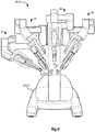
- FIG. 12 illustrates, as an example, the Image Capturing System 3020 which has a robot or movable arm 1101 which is mounted to a base 1106.
- the robot arm 1101 comprises a carousel 1107, first link 1102, second link 1103, wrist 1104, and C-arm 1105.
- the carousel 1107 is rotatable (as indicted by arrow "a") relative to the base 1106 using a carousel joint 1108.
- the first link 1102 is rotatable (as indicated by arrow "b") relative to the carousel 1107 using a shoulder joint 1109.
- the second link 1103 is rotatable (as indicated by arrow "c") relative to the first link 1102 using an elbow joint 1110.
- the wrist 1104 is rotatable (as indicated by arrow “d") relative to the second link 1103 using a roll joint 1111.
- the C-arm 1105 is rotatable (as indicated by arrow “e") relative to the wrist 1104 using a pitch joint 1112 and rotatable (as indicated by arrow “j") relative to the wrist 1104 using a yaw joint 1121.
- the C-arm 1105 comprises a first limb 1113, second limb 1114, and a central portion 1115.
- the first and second limbs 1113, 1114 are extendable away from and towards (as indicated by arrow "f') the central element 1115 using an extender joint 1120.
- the first limb 1113 has an X-ray detector 1116 disposed at its distal end and the second limb 1114 has an X-ray source 1117 disposed at its distal end.
- the X-ray detector 1116 is rotatable (as indicated by arrow "g") relative to the distal end of the first limb 1113.
- the X-ray source 1117 is rotatable (as indicated by arrow "h") relative to the distal end of the second limb 1114.
- the X-ray source and X-ray detector are disposed on opposing ends of the C-arm 1105 so as to form an image capturing device.
- the C-arm 1105 may be positioned relative to the Patient so that the C-arm 1105 may be moved so that the image capturing device (comprising X-ray source 1117 and X-ray detector 1116) may capture a series of two-dimensional projections of one or more objects within a specified region of interest at a work site in the Patient.
- the series of two-dimensional projections may then be used to generate a three-dimensional computer model of the one or more objects in a conventional manner for cone beam computed tomography.
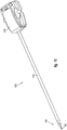
- FIG. 13 illustrates, as an example, an alternative Patient-Side Cart 4010 which is usable in the robotic system 3000 to introduce a plurality of articulated instruments to a work site through a single entry aperture in the Patient by an entry guide 200.
- the aperture may be a minimally invasive incision or a natural body orifice.
- the entry guide 200 is a cylindrical structure which is held and manipulated by a robot arm 4011, which is mounted on base 4015 and includes a setup arm 4012 and an entry guide manipulator 4013.
- the setup arm 4012 comprises a plurality of links and joints which are used to position the entry guide 200 at the aperture.
- the setup arm 4012 includes a prismatic joint for adjusting the height of the setup arm 4012 (as indicated by arrow "A") and a plurality of rotary joints for adjusting the horizontal position of the setup arm 4012 (as indicated by arrows "B” and “C”).
- the entry guide manipulator 4013 is used to robotically pivot the entry guide 200 (and the articulated instruments disposed within it at the time) in yaw, pitch and roll angular rotations about the pivot point as indicated by arrows D, E and F, respectively.
- Articulated instrument manipulators (not shown) reside in housing 4014.
- the entry guide 200 has articulated instruments such as articulated surgical instruments 231, 241 and an articulated stereo camera instrument 211 (or other image capturing device instrument) extending out of its distal end.
- the camera instrument 211 has a pair of stereo image capturing elements 311, 312 and a fiber optic cable 313 (coupled at its proximal end to a light source) housed in its tip.
- the surgical instruments 231, 241 have working ends 331, 341.
- the entry guide 200 may guide additional instruments as required for performing a medical procedure at a work site in the Patient. For example, as shown in a cross-sectional view of the entry guide 200 in FIG.
- a passage 351 is available for extending another articulated surgical tool through the entry guide 200 and out through its distal end.
- Passages 431, 441, are respectively used by the articulated surgical tool instruments 231, 241, and passage 321 is used for the articulated camera instrument 211.
- the stereo vision display 45 of the Console 3030 displays stereo images derived from the stereo images captured by the articulated camera instrument 211. Also, the processor 43 of the Console 3030 translates and transfers the mechanical motion of the input devices 41, 42 to actuate joints of devices, such as the entry guide 200, articulated surgical instruments 231, 241, and articulated camera instrument 211, which are associated at the time with the input devices 41, 42.
- Each of the articulated instruments comprises a plurality of actuatable joints and a plurality of links coupled to the joints.
- the second articulated instrument 241 comprises first, second, and third links 322, 324, 326, first and second joints 323, 325, and a wrist assembly 327.
- the first joint 323 couples the first and second links 322, 324 and the second joint 325 couples the second and third links 324, 326 so that the second link 324 may pivot about the first joint 323 in pitch and yaw while the first and third links 322, 326 remain parallel to each other.
- the first articulated instrument 231 and the camera articulated instrument 211 may be similarly constructed and operated.
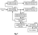
- the robotic system 1000 has a first manipulatable device 1001, a first image capturing device 1002, and a camera 1003.
- the first manipulatable device 1001 may be an instrument such as the one of the instruments 33, 35 held and manipulated by robot arms of the Patient-Side Cart 3010.
- the first manipulatable device 1001 may be an entry guide through which articulated instruments extend such as the entry guide 200 held and manipulated by the robot arm of the Patient-Side Cart 4010.
- a second manipulatable device 1004 is also shown which may be another device such as the first manipulatable device 1001.
- a second image capturing device 1005 is also shown which may provide a different imaging modality than that of the first image capturing device 1002.
- two manipulatable devices and two image capturing devices are shown for illustrative purposes, it is to be appreciated that in practice, more or less of each of such devices may be included in the robotic system 1000 to perform a task or procedure on an object at a work site. Additional cameras may also be included.
- a device controller 1021 controls movement of the robot arm 1011 to position and orient a working end of the first manipulatable device 1001 in response to commands from an input unit 1031.
- the input unit 1031 may be a user operated input device, such as one of the input devices 41, 42 or the foot pedal 44 of the console 3030.
- the input unit 1031 may be a processor, such as the processor 43 of the console 3030, executing stored program instructions.
- the input unit 1031 may be coupled control logic which communicates through bus 1040 with one or more of the controllers 1022, 1023, 1024, 1025 and/or input units 1032, 1033, 1034, 1035 associated with the first image capturing device 1002, the camera 1003, the second manipulatable device 1004, and the second image capturing device 1005.
- a device controller 1024 controls movement of the robot arm 1014 to position and orient a working end of the second manipulatable device 1004 in response to commands from an input unit 1034.
- the input unit 1034 may be a user operated input device, such as one of the input devices 41, 42 or the foot pedal 44 of the console 3030.
- the input unit 1034 may be a processor, such as the processor 43 of the console 3030, executing stored program instructions.
- the input unit 1034 may be coupled control logic which communicates through bus 1040 with one or more of the controllers 1021, 1022, 1023, 1025 and/or input units 1031, 1032, 1033, 1035 associated with the first manipulatable device 1001, the first image capturing device 1002, the camera 1003, and the second image capturing device 1005.
- the first image capturing device 1002 is manipulatable by its robot arm 1012 (or other motorized mechanism) to capture a plurality of two-dimensional image slices or projections of an object at the work site from which a three-dimensional model of the object may be computer generated without prior knowledge of the shape of the object using an imaging modality such as ultrasound, X-ray fluoroscopy, Computed Tomography (CT), and Magnetic Resonance Imaging (MRI).
- a controller 1022 controls movement of the robot arm 1012 to position and orient the first image capturing device 1002 in response to commands from an input unit 1032.
- the input unit 1032 may be a user operated input device, such as one of the input devices 41, 42 of the console 3030.
- the input unit 1032 may be a processor, such as the processor 43 of the console 3030, executing stored program instructions.
- the input unit 1032 may be coupled control logic which communicates through bus 1040 with one or more of the controllers 1021, 1023, 1024, 1025 and/or input units 1031, 1033, 1034, 1035 associated with the first manipulatable device 1001, the camera 1003, the second manipulatable device 1004, and the second image capturing device 1005.
- the first image capturing device 1002 and its robot arm 1012 may be combined to form an image capturing system such as the Image Capturing System 3020.
- the second image capturing device 1005 may be similarly constructed and operated as the first image capturing device 1002 to capture a plurality of two-dimensional image projections of an object at the work site from which a three-dimensional model of the object may be computer generated without prior knowledge of the shape of the object using an imaging modality such as ultrasound, X-ray fluoroscopy, Computed Tomography (CT), and Magnetic Resonance Imaging (MRI).
- an imaging modality such as ultrasound, X-ray fluoroscopy, Computed Tomography (CT), and Magnetic Resonance Imaging (MRI).
- CT Computed Tomography
- MRI Magnetic Resonance Imaging
- different imaging modalities are provided by the first and second image capturing devices 1002, 1005.
- a controller 1025 controls movement of the robot arm 1015 to position and orient the second image capturing device 1005 in response to commands from an input unit 1035.
- the input unit 1035 may be a user operated input device, such as one of the input devices 41, 42 of the console 3030.
- the input unit 1035 may be a processor, such as the processor 43 of the console 3030, executing stored program instructions.
- the input unit 1035 may be coupled control logic which communicates through bus 1040 with one or more of the controllers 1021, 1022, 1023, 1024, and/or input units 1031, 1032, 1033, 1034, associated with the first manipulatable device 1001, the first image capturing device 1002, the camera 1003, and the second manipulatable device 1004.
- the second image capturing device 1005 and its robot arm 1015 may be combined to form an image capturing system such as the Image Capturing System 3020.
- the second image capturing device 1005 may be constructed differently than that of the first image capturing device 1002.
- the second image capturing device 1005 may be held, positioned, and oriented by one of the first and second manipulatable devices 1001, 1004 rather than having its own robot arm, controller, and input unit.
- Examples of such a second image capturing device include a drop-in ultrasound probe or an optical coherent tomography probe.
- an ultrasound probe see, e.g., U.S. 2007/0021738 A1 entitled "Laparoscopic Ultrasound Robotic Surgical System.”
- the camera 1003 may be held and manipulated by a robot arm 1013 to capture stereoscopic images of work site, such as the endoscope 37 of FIG. 9 .
- the camera 1003 may be the articulated camera instrument 211 of FIG. 14 .
- a controller 1023 controls movement of the robot arm 1013 (or joints of the articulated camera instrument 211) to position and orient an image capturing element of the camera 1003 in response to commands from an input unit 1033.
- the input unit 1033 may be a user operated input device, such as one of the input devices 41, 42 of the console 3030.
- the input unit 1033 may be a processor, such as the processor 43 of the console 3030, executing stored program instructions.
- the input unit 1033 may be coupled control logic which communicates through bus 1040 with one or more of the controllers 1021, 1022, 1024, 1025 and/or input units 1031, 1032, 1034, 1035 associated with the first manipulatable device 1001, the image capturing device 1002, the second manipulatable device 1004, and the second image capturing device 1005.
- the camera 1003 may be held, positioned, and oriented by one of the first and second manipulatable devices 1001, 1004 rather than having its own robot arm, controller, and input unit.
- the camera may be a tethered camera which is orientable by a manipulatable device pulling on the tether(s). In this case, the camera would not have its own robot arm, controller, and input unit.
- An example of such a tethered camera is described in U.S. Patent Application Publication No. 2012/02900134 , entitled "Estimation of a Position and Orientation of a Frame Used in Controlling Movement of a Tool.”
- Each of the robot arms 1011, 1012, 1013, 1014, 1015 includes a plurality of links and a plurality of actuatable joints whose positions and/or velocities are sensed by a plurality of joint sensors.
- Information from the plurality of joint sensors of each robot arm 1011, 1012, 1013, 1014, 1015 is provided to its respective controller 1021, 1022, 1023, 1024, 1025 for control purposes and may be provided to one or more of the other controllers over bus 1040 for collision avoidance purposes, since this joint information indicates configuration information for the robot arms 1011,1012,1013,1014,1015.
- Each of the control units 1021-1025 may include at least one processing unit and memory.
- the processing unit may control operation and/or execution of hardware and/or software in the respective control unit 1021-1025.
- Each of the processing units may include one or more central processing units (CPUs), multi-core processors, microprocessors, microcontrollers, digital signal processors, field programmable gate arrays (FPGAs), custom processors/application specific integrated circuits (ASICs), and/or the like.
- the memory may be used to store one or more software and/or firmware applications as well as various data structures to be used by the respective control unit 1021-1025.
- the memory may also include one or more types of machine readable media.
- machine readable media may include floppy disk, flexible disk, hard disk, magnetic tape, any other magnetic medium, CD-ROM, any other optical medium, punch cards, paper tape, any other physical medium with patterns of holes, RAM, PROM, EPROM, FLASH-EPROM, any other memory chip or cartridge, and/or any other medium from which a processor or computer is adapted to read.
- the robotic system 1000 also includes a stereo viewer or display 1051 for displaying stereo images which have been generated by an image processor 1050 from images captured by the stereo camera 1003 and/or three-dimensional computer models of one or more objects which have been generated by the image processor 1050 from the plurality of two-dimensional image slices of the one or more objects captured by the first image capturing device 1002 and/or second image capturing device 1005.
- the image processor 1050 registers the images so that the three-dimensional computer models of the one or more objects are properly superimposed on and positioned relative to images of the one or more objects in the stereo images derived from images captured by the stereo camera 1003.
- FIGS. 3 , 4 respectively illustrate, as examples, flow diagrams of methods 2000, 2500 which may be implemented in the robotic system 1000 for avoiding a collision between independently operated image capturing device and manipulatable device robot arms.
- the methods 2000, 2500 are essentially the same method taken from different perspectives.
- the method 2000 is from the perspective of an image capturing device reference frame and may be performed by an image capturing device controller and the method 2500 is from the perspective of a manipulatable device reference frame and may be performed by a manipulatable device controller.
- manipulatable device when the working end of more than one device is viewable within the field of view of the image capturing device, each of those devices are to be processed as the described manipulatable device according to the methods so that collisions may be avoided between their robot arms and the robot arm of the image capturing device.
- the robotic system 1000 is the medical robotic system 3000 of FIG. 8 and it includes the Patient-Side Cart 3010 of FIG. 9 , the relevant blocks of both methods 2000, 2500 are performed for each of the manipulatable devices 31, 33, 35, 37 that is viewable in images captured by the image capturing device 3020.
- the robotic system 1000 is the medical robotic system 3000 of FIG.
- only one of the methods 2000, 2500 is performed to avoid collisions between robot arms.
- only one of the device controllers preferably performs the collision avoidance method. The controller taking such action may be pre-established, user selected, or selected by certain criteria.
- the Surgeon may interact with a menu being displayed on the stereo viewer 45 to select either the control unit 3021 to perform the method 2000 or the processor 43 to perform the method 2500.
- the control unit 3021 controls movement of the robot arm 1101 which holds and manipulates the image capturing device 1116, 1117 of the Image Capturing System 3020.
- the processor 43 implements a controller which controls movement of the robot arm 34 that holds and manipulates the instrument 33, which may be the manipulatable device for the purpose of this example.
- the manipulatable device referred to in methods 2000, 2500 is the entry guide 200 rather than one of the articulated instruments 211, 231, 241.
- it is the entry guide manipulator 4013 that is at risk of colliding with or being struck by the robot arm 1101 of the Image Capturing System 3020.
- the articulated instruments 211, 231, 241 do not have significant portions of any robot arms extending outside the Patient's body. They merely have manipulators whose movements are generally confined to be within a housing area 4014 of the entry guide manipulator 4013 as shown in FIG. 13 .
- collision avoidance between the robot arm 1101 of the Image Capturing System 3020 and the entry guide manipulator 4013 may be simpler than collision avoidance between the robot arm 1101 of the Image Capturing System 3020 and the robot arms 32, 34, 36, 38 of the Patient-Side Cart 3010. This is because not only are there more robot arms 32, 34, 36, 38 of the Patient-Side Cart 3010 for the robot arm 1101 of the Image Capturing System 3020 to collide with, but also because the robot arms 32, 34, 36, 38 of the Patient-Side Cart 3010 may move more often than the entry guide robot manipulator 4013 of the Patient-Side Cart 4010.
- FIG. 2 illustrates, as an example, a flow diagram of a method 9000, which is implemented in the robotic system 1000, for registering an image capturing device robot arm and a manipulatable device robot arm.
- a method 9000 which is implemented in the robotic system 1000, for registering an image capturing device robot arm and a manipulatable device robot arm.
- higher accuracy registrations are performed as the image capturing device robot arm moves closer to the manipulatable device robot arm.
- This multi-step approach provides high accuracy registration in a safe manner.
- the method performs a low accuracy registration (e.g., within an accuracy range of tens of centimeters) of the image capturing device robot arm and the manipulatable device robot arm relative to a common reference frame at their initial positions using an external tracker system and kinematic data for the robot arms.
- the external tracker system may be of the transmitter/receiver type which conventionally employs transmitters, which are strategically disposed on known locations of the robot arms of the image capturing device and the manipulatable device, and one or multiple receivers, which are disposed within transmission distance of the transmitters.
- the external tracker system may be of the optical type which conventionally employs optically discernible targets, which are strategically disposed on known locations of the robot arms of the image capturing device and the manipulatable device, and one or multiple optical detectors, which are disposed so as to have an unobstructed view of the targets.
- the kinematic data may be provided, for example, by encoders disposed to sense joint positions of the image capturing device robot arm and the manipulatable device robot arm. The joint positions may then be combined in a conventional manner using knowledge of the construction, shapes, and sizes of the robot arms to estimate the configurations of the robot arms.
- the image capturing device is moved towards the manipulatable device robot arm to assume a low-risk setup position that is close enough to allow the image capturing device being held by the image capturing device robot arm to capture images of at least a portion of the manipulatable device robot arm while being sufficiently far enough away from the manipulatable device robot arm to ensure that the image capturing device robot arm does not collide with the manipulatable device robot arm.
- the method also takes into account the current low accuracy level of the registration through a first safety margin that ensures no collision will occur between the image capturing device robot arm and the manipulatable device robot arm.
- the first safety margin may maintain a distance of at least ten centimeters between the image capturing device robot arm and the manipulatable device robot arm to account for the current low accuracy in determining the relative positions of those two robot arms.
- the movement of the image capturing device robot arm may be performed, for example, by an operator commanding such movement through a robot arm controller with assistance from the robot arm controller to inhibit unsafe movement.
- the robot arm controller may provide force feedback to the operator through a haptic device, such as a joystick, to provide resistance against the unsafe movement. Alternatively, it may be performed automatically by the robot arm controller in either a direct mode or cross-coupled mode.
- the method performs a mid accuracy registration (e.g., within an accuracy range of centimeters) of the image capturing device robot arm and the manipulatable device robot arm relative to the common reference frame at their current positions using one or more captured images of at least a part of the manipulatable device robot arm and kinematics data for the robot arms.
- a mid accuracy registration e.g., within an accuracy range of centimeters
- the method then waits for an operator's command to initiate movement of the image capturing device robot arm to capture images of a user specified region of interest.
- the image capturing device is moved towards the manipulatable device robot arm to assume an image capturing setup position that is close enough to allow the image capturing device being held by the image capturing device robot arm to capture images of a user specified region of interest while being sufficiently far enough away from the manipulatable device robot arm to ensure that the image capturing device robot arm does not collide with the manipulatable device robot arm.
- the method takes into account the current mid accuracy level of the registration through a second safety margin that ensures no collision will occur between the image capturing device robot arm and the manipulatable device robot arm.
- the second safety margin may maintain a distance of at least one centimeter between the image capturing device robot arm and the manipulatable device robot arm to account for the current mid accuracy in determining the relative positions of those two robot arms.
- the movement of the image capturing device robot arm may be performed, for example, by an operator commanding such movement through a robot arm controller with assistance from the robot arm controller to inhibit unsafe movement.
- the robot arm controller may provide force feedback to the operator through a haptic device, such as a joystick, to provide resistance against the unsafe movement.
- the movement may be performed automatically by the image capturing device controller directly or through a coupled control mode with the manipulatable device controller.
- the method commands the image capturing device robot arm to move relative to the region of interest and commands the image capturing device being held by the image capturing device robot arm to capture images of the region of interest during such movement while avoiding a collision of the image capturing device robot arm and the manipulatable device robot arm.
- the image capturing device captures images of at least a working end of a manipulatable device being held by the manipulatable device robot arm. In this case, the working end of the manipulatable device is proximate to the region of interest so as to be within the field of view of the image capturing device.
- the method performs at least one high accuracy registration (e.g., within an accuracy range of millimeters) of the image capturing device robot arm and the manipulatable device robot arm relative to the common reference frame at their current positions using one or more of the captured images of the working end of the manipulatable device and kinematics data for the robot arms.
- at least one high accuracy registration e.g., within an accuracy range of millimeters
- the method which is preferably performed by the image capturing device controller 1022, receives information of the configuration of the robot arm that holds and manipulates the image capturing device.
- the robot arm configuration is determinable from sensed positions of the joints and known geometries of the links and other structure making up the robot arm.
- such robot arm configuration information may be provided from a plurality of sensors in the image capturing device robot arm, such as encoders which are coupled to actuators of the joints. Alternatively, it may be joint positions being commanded by the image capturing device controller 1022 in response to commands from the input device 1032.
- the method determines whether or not it is time to perform a registration of the image capturing device to the manipulatable device. Such registration may be performed once at the start of the method or it may be performed periodically to correct any registration errors that may accrue over time. If the determination in block 2002 is YES, then the method performs the registration by performing blocks 2003, 2004. On the other hand, if the determination in block 2002 is NO, then registration is skipped by the method jumping to block 2005.
- the method receives an image, which has been captured by the image capturing device, of the working end of the manipulatable device.
- the received image will be a two-dimensional slice or projection of the working end of the manipulatable device and any other objects within an image capturing cone of the image capturing device.
- the method determines the position and orientation (i.e., pose) of the working end of the manipulatable device relative to a reference frame of the image capturing device, which corresponds to a position and orientation of the image capturing cone or field of view of the image capturing device.
- the method conventionally uses artificial and/or natural features of the working end that are discernible in the received image.
- artificial features include such things as markings or structure specifically placed on the working end to aid in determining their pose (i.e., position and orientation).
- Natural features include such things as the shape and known geometries of structure of the working end of the manipulatable device. The pose of the working end may be determinable even though the working end may be partially occluded.
- the working end may be occluded by portions of a patient's anatomy, other portions of the manipulatable device, portions of the image capturing device, other medical instruments, and/or the like.
- the patient's anatomy may include soft tissue, bone, teeth, and/or the like.
- the sequence of images captured by the image capturing device and received as the method loops through blocks 2001-2009 may be used to refine the determination of the pose.
- conventional tool tracking techniques may be used that aid in and serve to further refine the determination of the pose of the working end of the manipulatable device. For additional details on such pose determining techniques and artifacts, see U.S. Pat. No. 8,108,072 entitled “Methods and systems for robotic instrument tool tracking with adaptive fusion of kinematics information and image information," and U.S. Publication No. 2010/0168763 A1 entitled "Configuration marker design and detection for instrument tracking.”
- the method receives information of the configuration of the robot arm that holds and manipulates the manipulatable device.
- the robot arm comprises a plurality of links coupled together by a plurality of joints
- the robot arm configuration is determinable from sensed positions of the joints and known geometries of the links and other structure making up the robot arm.
- such robot arm configuration information may be provided from a plurality of sensors of the manipulatable device robot arm, such as encoders which are coupled to actuators of the joints.
- it may be joint positions being commanded by the manipulatable device controller 1021 in response to commands from the input device 1031.
- it may be some joint positions being provided by tracking the working end of instruments in endoscopic images which may provide better accuracy compared to encoder measurements.
- the information of the configuration of the robot arm preferably includes either the sensed joint positions or commanded joint positions of the manipulatable device robot arm. If, on the other hand, there is only one robot arm configuration that may correspond to the pose of the working end of its held manipulatable device, then the robot arm configuration may theoretically be determined from the determined pose of the working end of the manipulatable device, the known construction and geometries (e.g., size and shape) of the manipulatable device and its robot arm, and the position of the base of the manipulatable device robot arm.
- DOF degree-of-freedom
- the base position of the manipulatable device robot arm is necessary.
- the base position is fixed and only needs to be determined once and stored in a memory.
- the base position may be determined, for example, by external sensors such as pressure sensors strategically disposed on the floor.
- the base position may be determined by a transmitter/receiver system in which one or more transmitters are disposed on the base with one or more receivers disposed at fixed locations.
- the base position (as well as the robot arm configuration) may be determined by an optical tracking system or by any other well known position sensing means.
- the method determines the configuration and position of the manipulatable device robot arm in the image capturing device frame of reference. Since the pose of the working end of the manipulatable device relative to the image capturing device reference frame has already been determined in block 2004, the determination of the configuration and position of its robot arm in the image capturing device frame of reference is determined in this case by using the known construction and geometries of the manipulatable device and its robot arm along with the information of the manipulatable device robot arm configuration received in block 2005.
- the method determines the configuration and position of the image capturing device robot arm in the image capturing device reference frame. Since the image capturing device reference frame is defined by the pose of the distal end of the image capturing device robot arm, it is a simple matter to determine the configuration and position of the image capturing device robot arm in the image capturing device reference frame using the known construction and geometries of the image capturing device and its robot arm along with the information of the image capturing device robot arm configuration received in block 2001.
- the method determines whether an imminent collision is threatened between the image capturing device robot arm and the manipulatable device robot arm.
- the determination is made by using the information received or determined in blocks 2001-2007 for the current process cycle and previous process cycles.
- time series information not only can the trajectories of the two arms be predicted, but the rates at which they are moving may be estimated.
- a collision prediction may be made. When the predicted collision is within a specified time period, then the collision is considered to be imminent, requiring immediate action.
- the collision prediction may use a minimum distance between the image capturing device robot arm and the manipulatable device robot arm.
- the method preferably approximates links of the robot arms with geometric shapes that are dimensionally slightly larger than the actual links for safety purposes. Since the geometric shapes of the image capturing device robot arm and the geometric shapes of the manipulating device robot arm occupy known positions and orientations relative to each other at this point, it is a straightforward calculation to determine a minimum distance between the geometric shapes representing the image capturing device robot arm and the geometric shapes representing the manipulating device robot arm.
- block 2008 may be used to detect additional undesirable relationships between the manipulating device robot arm and the image capturing device robot arm other than an imminent collision.
- block 2008 may be used to detect when the manipulating device robot arm and the image capturing device robot arm are in too close a proximity to each other, even though a collision is not imminent.
- block 2008 may be used to detect that the manipulating device robot arm is obstructing a region of interest for which the image capturing device is to capture images thereof.
- the method jumps back to block 2001 to perform blocks 2001-2008 for a next process cycle.
- the method commands the image capturing device robot arm to take an action to avoid a collision with the robot arm of the manipulatable device.
- the commanded action may be to temporarily halt movement of the image capturing device robot arm until the manipulatable device robot arm has moved to a collision safe position.
- the speed of its movement may be adjusted instead to avoid collision with the manipulatable device robot arm.
- an alternative arm configuration may be commanded to avoid collision with the manipulatable device robot arm.
- the movement of the image capturing device robot arm may be halted and the collision avoidance task may be passed over to the manipulatable device controller to perform the method 2500 of FIG. 4 .
- the method After performing block 2009, the method then loops back to block 2001 to process information for a next process cycle.
- the method which is preferably performed by the manipulatable device controller 1021, receives information of the configuration of the robot arm that holds and manipulates the manipulatable device.
- the robot arm configuration is determinable from sensed positions of the joints and known geometries of the links and other structure making up the robot arm.
- such robot arm configuration information may be provided from a plurality of sensors in the image capturing device robot arm, such as encoders which are coupled to actuators of the joints.
- it may be joint positions being commanded by the manipulatable device controller 1021 in response to commands from the input device 1031.
- it may be some joint positions being provided by tracking the working end of instruments in endoscopic images which may provide better accuracy compared to encoder measurements.
- the method determines whether or not it is time to perform a registration of the image capturing device to the manipulatable device. Such registration may be performed once at the start of the method or it may be performed periodically to correct any registration errors that may accrue over time. If the determination in block 2502 is YES, then the method performs the registration by performing blocks 2503, 2504. On the other hand, if the determination in block 2502 is NO, then registration is skipped by the method jumping to block 2505.
- the method receives an image, which has been captured by the image capturing device, of the working end of the manipulatable device.
- the received image will be a two-dimensional slice or projection of the working end of the manipulatable device and any other objects within an image capturing cone or field of view of the image capturing device.
- the image may be received by the manipulatable device controller 1021 over a bus 1040 (or cable 3050 of FIG. 8 ) from the first image capturing device 1002 or a processor in an image capturing system that includes the first image capturing device 1002.
- the method determines the position and orientation (i.e., pose) of the working end of the manipulatable device relative to a reference frame of the image capturing device in the same manner as described in reference to block 2004 of FIG. 3 .
- the method receives information of the configuration of the robot arm that holds and manipulates the image capturing device.
- the robot arm comprises a plurality of links coupled together by a plurality of joints
- the robot arm configuration is determinable from sensed positions of the joints and known geometries of the links and other structure making up the robot arm.
- such robot arm configuration information may be provided from a plurality of sensors of the manipulatable device robot arm, such as encoders which are coupled to actuators of the joints. Alternatively, it may be joint positions being commanded by the image capturing device controller 1022 in response to commands from the input device 1032.
- the method determines the configuration and position of the manipulatable device robot arm in the manipulatable device reference frame. Since the manipulatable device reference frame is defined by the pose of the distal end of the manipulatable device robot arm, it is a simple matter to determine the configuration and position of the manipulatable device robot arm in the manipulatable device reference frame using the information received in block 2501 and the known construction and geometries of the manipulatable device and its robot arm.
- the method determines the configuration and position of the image capturing device robot arm in the manipulatable device frame of reference.
- the method may determine the transform M I T by comparing points of the working end of the manipulatable device in the image reference frame, using information of its pose determined in block 2504, with corresponding points of the working end of the manipulatable device in the manipulatable device reference frame, using information of its pose determined from the information of the manipulatable device robot arm configuration which was received in block 2501 and prior known information of the size, shape, and construction of the manipulatable device.
- U.S. Patent Application Publication No. 2012/02900134 entitled "Estimation of a Position and Orientation of a Frame Used in Controlling Movement of a Tool.”
- block 2508 the method determines whether an imminent collision is threatened between the image capturing device robot arm and the manipulatable device robot arm in a similar manner as described in reference to block 2008 of FIG. 3 .
- block 2508 may also be used to detect additional undesirable relationships between the manipulating device robot arm and the image capturing device robot arm other than an imminent collision.
- the method may command either the manipulatable device robot arm or the image capturing device robot arm, through the image capturing device controller 1022, to take a collision avoidance action.
- the entity performing the collision avoidance action and the particular collision avoidance action taken may take different forms depending upon system factors. One factor is the nature of the tasks being performed at the time by the image capturing device and the manipulatable device. Another factor is the type or structure of the robot arms or their corresponding velocity and acceleration at the moment when an imminent collision is detected.
- the robotic system 1000 is the medical robotic system 3000 and the manipulatable device is one of the instruments 33, 35 which is being used at the time to perform a delicate surgery on a Patient, then it is desirable not to disturb the robot arm holding the instrument. Therefore, in this case it may be preferable to take action by modifying the trajectory of the image capturing device robot arm 1101 to avoid a collision. To avoid such collision, movement of the image capturing device robot arm 1101 may be temporarily halted until the manipulatable device robot arm has moved to a collision safe position. Alternatively, rather than halting all movement of the image capturing device robot arm 1101, the speed and/or direction of its movement may be adjusted instead to avoid collision with the manipulatable device robot arm.
- the image capturing device and manipulatable device robot arms may have redundant degrees-of-freedom (DOF)
- DOF degrees-of-freedom
- one of the robot arms with such redundant DOF may be configured in an alternative configuration without affecting the pose of its held device.
- the manipulatable device robot arm has redundant DOF, then it would not be necessary to modify the trajectory of the image capturing device since the manipulatable device robot arm may be configured instead to an alternative configuration without significantly impacting the manipulation of its held manipulatable device.
- one of the first and second robot arms is selected for using an alternative configuration to avoid the imminent collision by processing differences between current configurations of the first and second robot arms and their respective pluralities of possible configurations to minimize a cost function.
- the selection may be made by processing required joint movements of the first and second robotic systems to move from their current configurations to others of their respective pluralities of possible configurations to minimize a cost function.
- One possible cost function may be based on an inverse square of the minimum distance between the first and second robot arms.
- a second possible cost function may be based on a weighted average of an inverse square of distances between links of the first and second robot arm, with each link being associated with a passive or active degree of freedom.
- a third possible cost function may be based on the second cost function, but may account for only distances which are below a threshold, such as a threshold within an order of magnitude of a desired safety margin.
- a fourth possible cost function may be based on a modified version of the second cost function where the distances are measured between virtual objects or buffer regions surrounding the links of the first and second robot arms.
- a fifth possible cost function may include the buffer regions of the fourth cost function and the distance threshold of the third cost function.
- a sixth possible cost function may be based on a constrained manipulability index for the first and second robot arms with the manipulability index estimating an ability of the first or second robot arm to move in arbitrary directions around the alternative configuration.
- a seventh possible cost function may be based on virtual potential fields applied to the links and/or joints of the first and second robot arms. As an example, each link and/or joint of the first and second robot arms may have a virtual electric charge assigned to it and the induced virtual repelling force may be integrated between the first and second robot arms to determine the seventh cost function.
- the method After performing block 2509, the method then loops back to block 2501 to process information for a next process cycle.
- an update or recalibration of initial registration transforms for work site objects may be performed.
- the robotic system 1000 is the medical robotic system 3000
- the work site objects include the instruments 31, 33, 35, the endoscope 37, the image capturing device 1116, 1117 of the Image Capturing System 3020, and the Patient's anatomy.
- registration errors may accumulate or otherwise occur in some manner.
- the image capturing device and the manipulatable device are independently operated typically by different people.
- an Assistant standing next to the Operating Table 3040 may operate the control unit 3021 to control movement of the Image Capturing System 3020 and the Surgeon may operate the input devices 41, 42 of the Console 3030 to control movement of the manipulatable devices 33, 35.
- the Surgeon may want to supplement those images with three-dimensional X-ray images of an interior view of the anatomical structure.
- a method for automatically controlling the Image Capturing System 3020 to provide the Surgeon's desired view of a region of interest is useful.
- FIG. 5 illustrates, as an example, a method 4000 implemented in the robotic system 1000 for automatically controlling movement of the image capturing device so as to capture images of a user specified region of interest while avoiding a collision between its robot arm and another robot arm.
- the method receives information of a user specified region of interest at the work site.
- the region of interest is specified relative to an image of the work site being displayed at the time on the display 1051.
- the images being displayed on the display 1051 may have been derived from images captured by a camera 1003 such as a stereoscopic endoscope. Alternatively, they may have been derived from images captured by a second image capturing device 1005 such as an ultrasound probe. Alternatively, the images being displayed on the display 1051 may include both images derived from those captured by a camera 1003 and images derived from those captured by a second image capturing device 1005 by registering and superimposing the images.
- the user may specify the region of interest by simply using an input device such as a mouse to control movement of a cursor on the display 1051 so that the path of the cursor defines the region of interest.
- the user may use a gaze tracker and a user controlled switch to indicate when the user's current gaze point on the display 1051 is to specify a center of a region of interest.
- the shape of the region of interest may be predefined or it may be determined by the shape of an object upon which the user is currently gazing.
- the user may telerobotically control movement. of a working end of the manipulatable device so that it touches an object at the work site to indicate that the region of interest should be the object that has been touched.
- the method receives information of the initial arm configurations and base positions of the image capturing device robot arm and a manipulatable device robot arm.
- Information of the initial arm configurations may be provided by information of their construction and information of their joint positions which is received from a plurality of sensors of the robot arms.
- Information of the base positions in the world reference frame may be provided by external sensors which provide such information.
- an external sensor is an optical sensor that is used in an optical tracking system.
- a pressure transducer that is one of an array of pressure transducers strategically placed at known positions on the floor of the work site.
- the method determines a set-up position for the image capturing device so that it is properly positioned to capture the requested images of the user specified region of interest.
- the method first translates the region of interest from the display reference frame to an image capturing device reference frame using a previously determined transform and information received in block 4002. It then translates the region of interest from the image capturing device reference frame to the world reference frame using a previously determined transform and information received in block 4002. With the region of interest known in the world reference frame, the method then determines a set-up position from which the image capturing device may capture the requested images of the user specified region of interest without colliding with the initial position in the world reference frame of the manipulatable device robot arm.
- the method determines a plan of motion for the image capturing device to capture the requested images of the user specified region of interest.
- the plan of motion may comprise planned movement of the links 1102, 1103, the wrist 1104 and the C-arm 1105.
- the method commands movement of the image capturing device to its set-up position after receiving a command to do so from the user.
- the image capturing device is the image capturing device 1116, 1117 of the Image Capturing System 3020 of FIG. 12
- the commanded movement typically entails rotating the carousel joint 1108 so that the robot arm 1101 is facing the region of interest and rotating the shoulder joint 1109, elbow joint 1110, roll joint 1111, pitch joint 1112, and yaw joint 1121 so that the X-ray source 1117 and X-ray detector 1116 (i.e., the image capturing device) are properly positioned to start capturing the requested images of the user specified region of interest.
- the method commands incremental movement of the image capturing device in accordance with the plan of motion while avoiding a collision between the image capturing device robot arm and the manipulatable device robot arm. Additional details of tasks performed by the method in block 4006 are described in reference to FIG. 6 .
- the method determines whether the plan of motion is completed. If the determination in block 4007 is NO, then the method jumps back to block 4006 to command another incremental movement of the image capturing device according to the plan of motion while avoiding a collision between the image capturing device robot arm and the manipulatable device robot arm.
- the method commands the image capturing device to move back to its initial position or a predefined parking position upon receiving a command to do so from the user, so that it is out of the way and presents no further risk of collision with the manipulatable device robot arm.
- FIG. 6 illustrates, as an example, a flow diagram of a method for performing block 4006 of the method 4000.
- FIG. 7 illustrates a block diagram of a portion of a robotic system which is used for collision avoidance between two independently operated robot arms.
- a manipulatable device robot arm simulator 6003, an imminent collision detector 6021, an image capturing device robot arm simulator 6013, and an incremental motion generator 6004 are preferably implemented in a conventional manner by a processor executing program code.
- the method receives a movement command for the manipulatable device robot arm.
- the output of the manipulatable device controller 6011 provides joint commands for the manipulatable device robot arm actuators 6012.
- the method determines the position and configuration for the manipulatable device robot arm. For example, referring to FIG. 7 , the manipulatable device robot arm simulator unit 6003 generates information of the position and configuration for the manipulatable device robot arm using the joint commands from the manipulatable device controller 6011 and prior knowledge of the construction of the manipulatable device robot arm.
- the method determines a desired incremental movement of the image capturing device.
- the incremental motion generator 6004 generates a desired incremental movement of the image capturing device using information of the plan of motion determined in block 4004 of FIG. 5 and stored in memory 6005.
- the desired incremental movement in this case depends upon a desired velocity for the movement of the image capturing device and a process cycle period for looping through blocks 4006-4007 of FIG. 5 .
- the method determines the position and configuration for the image capturing device robot arm. For example, referring to FIG. 7 , the image capturing device robot arm simulator unit 6013 generates information of the position and configuration for the image capturing device robot arm using the desired incremental motion commands provided by the incremental motion generator 6004, knowledge of the current position and configuration of the image capturing device robot arm, and prior knowledge of the construction of the image capturing device robot arm.
- the method determines whether an imminent collision is threatened between the image capturing device robot arm and the manipulatable device robot arm in a similar manner as performed in block 2008 of FIG. 3 .
- the imminent collision detector 6021 determines whether a collision between the two arms is imminent by using the information provided by the robot arm simulators 6003, 6013 for the current process cycle and previous process cycles. By using time series information, not only can the trajectories of the two robot arms be predicted, but the rates at which they are moving may be estimated. With this information, a collision prediction may be made. When the predicted collision is within a specified time period, then the collision is considered to be imminent, requiring immediate action.
- the method commands the image capturing device robot arm to move according to the desired incremental movement.
- the method modifies the incremental movement command to avoid the imminent collision, using as examples, one of the actions described in reference to block 2009 of FIG. 3 .
- the imminent collision detector 6021 After the imminent collision detector 6021 has determined that a collision between the image capturing device robot arm and the manipulatable device robot arm is imminent, it sends an indication of such to the manipulatable device controller 6011, which in turn, relays the indication to the image capturing device controller 6001 so that it can take corrective action to avoid the collision.
- control units 1021-1025 and/or 3021 may include non-transient, tangible, machine readable media that include executable code that when run by one or more processors may cause the one or more processors (e.g., the processing units of control units 1021-1025 and/or 3021) to perform the processes of methods 2000, 2500, 4000, and/or 9000 as described above.
- processors e.g., the processing units of control units 1021-1025 and/or 3021
- machine readable media that may include the processes of methods 2000, 2500, 4000, and/or 9000 are, for example, floppy disk, flexible disk, hard disk, magnetic tape, any other magnetic medium, CD-ROM, any other optical medium, punch cards, paper tape, any other physical medium with patterns of holes, RAM, PROM, EPROM, FLASH-EPROM, any other memory chip or cartridge, and/or any other medium from which a processor or computer is adapted to read.
Landscapes
- Health & Medical Sciences (AREA)
- Engineering & Computer Science (AREA)
- Life Sciences & Earth Sciences (AREA)
- Medical Informatics (AREA)
- Surgery (AREA)
- Public Health (AREA)
- Molecular Biology (AREA)
- General Health & Medical Sciences (AREA)
- Veterinary Medicine (AREA)
- Nuclear Medicine, Radiotherapy & Molecular Imaging (AREA)
- Animal Behavior & Ethology (AREA)
- Biomedical Technology (AREA)
- Heart & Thoracic Surgery (AREA)
- Robotics (AREA)
- Pathology (AREA)
- Biophysics (AREA)
- Radiology & Medical Imaging (AREA)
- Optics & Photonics (AREA)
- High Energy & Nuclear Physics (AREA)
- Physics & Mathematics (AREA)
- Mechanical Engineering (AREA)
- Automation & Control Theory (AREA)
- Oral & Maxillofacial Surgery (AREA)
- Manipulator (AREA)
Priority Applications (1)
| Application Number | Priority Date | Filing Date | Title |
|---|---|---|---|
| EP21190869.4A EP3932628A1 (en) | 2012-12-10 | 2013-12-10 | Collision avoidance during controlled movement of image capturing device and manipulatable device movable arms |
Applications Claiming Priority (2)
| Application Number | Priority Date | Filing Date | Title |
|---|---|---|---|
| US201261735170P | 2012-12-10 | 2012-12-10 | |
| PCT/US2013/074163 WO2014093367A1 (en) | 2012-12-10 | 2013-12-10 | Collision avoidance during controlled movement of image capturing device and manipulatable device movable arms |
Related Child Applications (2)
| Application Number | Title | Priority Date | Filing Date |
|---|---|---|---|
| EP21190869.4A Division EP3932628A1 (en) | 2012-12-10 | 2013-12-10 | Collision avoidance during controlled movement of image capturing device and manipulatable device movable arms |
| EP21190869.4A Division-Into EP3932628A1 (en) | 2012-12-10 | 2013-12-10 | Collision avoidance during controlled movement of image capturing device and manipulatable device movable arms |
Publications (3)
| Publication Number | Publication Date |
|---|---|
| EP2928407A1 EP2928407A1 (en) | 2015-10-14 |
| EP2928407A4 EP2928407A4 (en) | 2016-10-19 |
| EP2928407B1 true EP2928407B1 (en) | 2021-09-29 |
Family
ID=50881820
Family Applications (2)
| Application Number | Title | Priority Date | Filing Date |
|---|---|---|---|
| EP13862685.8A Active EP2928407B1 (en) | 2012-12-10 | 2013-12-10 | Collision avoidance during controlled movement of image capturing device and manipulatable device movable arms |
| EP21190869.4A Pending EP3932628A1 (en) | 2012-12-10 | 2013-12-10 | Collision avoidance during controlled movement of image capturing device and manipulatable device movable arms |
Family Applications After (1)
| Application Number | Title | Priority Date | Filing Date |
|---|---|---|---|
| EP21190869.4A Pending EP3932628A1 (en) | 2012-12-10 | 2013-12-10 | Collision avoidance during controlled movement of image capturing device and manipulatable device movable arms |
Country Status (6)
| Country | Link |
|---|---|
| US (3) | US9259282B2 (cg-RX-API-DMAC7.html) |
| EP (2) | EP2928407B1 (cg-RX-API-DMAC7.html) |
| JP (2) | JP6293777B2 (cg-RX-API-DMAC7.html) |
| KR (1) | KR102218244B1 (cg-RX-API-DMAC7.html) |
| CN (3) | CN110279427B (cg-RX-API-DMAC7.html) |
| WO (1) | WO2014093367A1 (cg-RX-API-DMAC7.html) |
Families Citing this family (319)
| Publication number | Priority date | Publication date | Assignee | Title |
|---|---|---|---|---|
| US9948885B2 (en) * | 2003-12-12 | 2018-04-17 | Kurzweil Technologies, Inc. | Virtual encounters |
| US20110160905A1 (en) * | 2008-09-03 | 2011-06-30 | Honda Motor Co., Ltd. | Workpiece mounting system, workpiece mounting method, sunroof unit holding device, and sunroof unit holding method |
| US11871901B2 (en) | 2012-05-20 | 2024-01-16 | Cilag Gmbh International | Method for situational awareness for surgical network or surgical network connected device capable of adjusting function based on a sensed situation or usage |
| CN110279427B (zh) | 2012-12-10 | 2024-01-16 | 直观外科手术操作公司 | 图像采集装置和可操纵装置活动臂受控运动过程中的碰撞避免 |
| US9649765B2 (en) | 2013-03-11 | 2017-05-16 | Siemens Aktiengesellschaft | Reducing energy consumption of industrial robots by using new methods for motion path programming |
| KR20160008169A (ko) | 2013-03-14 | 2016-01-21 | 에스알아이 인터내셔널 | 컴팩트 로봇 리스트 |
| KR102283176B1 (ko) * | 2013-03-15 | 2021-07-29 | 인튜어티브 서지컬 오퍼레이션즈 인코포레이티드 | 로봇 수술 시스템에서의 수술 중 도구의 교환 |
| JP6396987B2 (ja) | 2013-03-15 | 2018-09-26 | エスアールアイ インターナショナルSRI International | 超精巧外科システム |
| JP2016512733A (ja) | 2013-03-15 | 2016-05-09 | インテュイティブ サージカル オペレーションズ, インコーポレイテッド | マニピュレータ関節動作を異方的に強調するためにゼロ空間を使用するシステム及び方法 |
| JP5713047B2 (ja) * | 2013-04-18 | 2015-05-07 | 株式会社安川電機 | 移動ロボット、移動ロボットの位置決めシステム、及び、移動ロボットの位置決め方法 |
| WO2015079740A1 (ja) * | 2013-11-28 | 2015-06-04 | 三菱電機株式会社 | ロボットシステムおよびロボットシステムの制御方法 |
| PL3076906T3 (pl) * | 2013-12-05 | 2018-12-31 | NowTechnologies Zrt. | Pojazd osobisty i urządzenie sterujące oraz odpowiedni sposób sterowania |
| EP3834752B1 (en) | 2013-12-11 | 2024-03-13 | Covidien LP | Wrist and jaw assemblies for robotic surgical systems |
| JP5850958B2 (ja) * | 2014-01-24 | 2016-02-03 | ファナック株式会社 | ワークを撮像するためのロボットプログラムを作成するロボットプログラミング装置 |
| EP3610820B1 (en) | 2014-03-17 | 2023-08-02 | Intuitive Surgical Operations, Inc. | Methods and devices for table pose tracking using fiducial markers |
| JP6644699B2 (ja) | 2014-03-19 | 2020-02-12 | インテュイティブ サージカル オペレーションズ, インコーポレイテッド | 視線追跡を使用する医療装置、システム、及び方法 |
| JP6689203B2 (ja) | 2014-03-19 | 2020-04-28 | インテュイティブ サージカル オペレーションズ, インコーポレイテッド | 立体ビューワのための視線追跡を統合する医療システム |
| US20150277398A1 (en) * | 2014-03-26 | 2015-10-01 | Siemens Industry Software Ltd. | Object manipulation driven robot offline programming for multiple robot system |
| US9922144B2 (en) | 2014-03-26 | 2018-03-20 | Siemens Industry Software Ltd. | Energy and cycle time efficiency based method for robot positioning |
| EP2930462B1 (en) * | 2014-04-08 | 2017-09-13 | Hexagon Technology Center GmbH | Method for generating information about a sensor chain of a coordinate measuring machine (CMM) |
| US9701011B2 (en) * | 2014-05-08 | 2017-07-11 | Siemens Industry Software Ltd. | Method for robotic energy saving tool search |
| US9815201B2 (en) | 2014-07-31 | 2017-11-14 | Siemens Industry Software Limited | Method and apparatus for industrial robotic energy saving optimization using fly-by |
| US9469029B2 (en) | 2014-07-31 | 2016-10-18 | Siemens Industry Software Ltd. | Method and apparatus for saving energy and reducing cycle time by optimal ordering of the industrial robotic path |
| EP3179955B1 (en) | 2014-08-13 | 2021-09-15 | Covidien LP | Robotically controlling mechanical advantage gripping |
| US9457469B2 (en) | 2014-08-14 | 2016-10-04 | Siemens Industry Software Ltd. | Method and apparatus for automatic and efficient location generation for cooperative motion |
| WO2016064993A1 (en) * | 2014-10-22 | 2016-04-28 | Carestream Health, Inc. | Mobile radiographic imaging apparatus |
| EP3212150B1 (en) * | 2014-10-27 | 2021-08-11 | Intuitive Surgical Operations, Inc. | System for registering to a surgical table |
| JP6676061B2 (ja) | 2014-10-27 | 2020-04-08 | インテュイティブ サージカル オペレーションズ, インコーポレイテッド | 統合された手術台運動のためのシステム及び方法 |
| KR102655083B1 (ko) | 2014-10-27 | 2024-04-08 | 인튜어티브 서지컬 오퍼레이션즈 인코포레이티드 | 브레이크 해제가 능동적으로 제어되는 의료 장치 |
| CN110584789B (zh) | 2014-10-27 | 2022-09-20 | 直观外科手术操作公司 | 用于器械干扰补偿的系统和方法 |
| JP6682512B2 (ja) | 2014-10-27 | 2020-04-15 | インテュイティブ サージカル オペレーションズ, インコーポレイテッド | 一体化された手術台のシステム及び方法 |
| WO2016069660A1 (en) | 2014-10-27 | 2016-05-06 | Intuitive Surgical Operations, Inc. | System and method for monitoring control points during reactive motion |
| WO2016126914A1 (en) * | 2015-02-05 | 2016-08-11 | Intuitive Surgical Operations, Inc. | System and method for anatomical markers |
| US10695142B2 (en) | 2015-02-19 | 2020-06-30 | Covidien Lp | Repositioning method of input device for robotic surgical system |
| AU2016229897B2 (en) | 2015-03-10 | 2020-07-16 | Covidien Lp | Measuring health of a connector member of a robotic surgical system |
| DE102015104821A1 (de) * | 2015-03-27 | 2016-09-29 | Medineering Gmbh | Chirurgisches Instrument, System, Haltearm sowie Verfahren |
| EP3282997B1 (en) * | 2015-04-15 | 2021-06-16 | Mobius Imaging, LLC | Integrated medical imaging and surgical robotic system |
| CN107666866A (zh) | 2015-06-03 | 2018-02-06 | 柯惠Lp公司 | 偏置器械驱动单元 |
| GB201509887D0 (en) | 2015-06-08 | 2015-07-22 | Univ Strathclyde | Remote operations system |
| DE202016102686U1 (de) | 2015-06-15 | 2016-06-23 | Knorr-Bremse Systeme für Nutzfahrzeuge GmbH | Scheibenbremse für ein Nutzfahrzeug und Bremsbelagsatz |
| CA2987637C (en) | 2015-06-16 | 2023-10-03 | Covidien Lp | Robotic surgical system torque transduction sensing |
| JP6719487B2 (ja) | 2015-06-23 | 2020-07-08 | コヴィディエン リミテッド パートナーシップ | ロボット外科手術アセンブリ |
| US10828115B2 (en) | 2015-07-23 | 2020-11-10 | Sri International | Robotic arm and robotic surgical system |
| US10034716B2 (en) * | 2015-09-14 | 2018-07-31 | Globus Medical, Inc. | Surgical robotic systems and methods thereof |
| JP6755305B2 (ja) | 2015-09-25 | 2020-09-16 | コヴィディエン リミテッド パートナーシップ | ロボット外科組立体およびその器具駆動コネクタ |
| US10299740B2 (en) * | 2015-09-29 | 2019-05-28 | General Electric Company | Methods and systems for cone-beam computed tomography |
| WO2017070275A1 (en) | 2015-10-23 | 2017-04-27 | Covidien Lp | Surgical system for detecting gradual changes in perfusion |
| US9955986B2 (en) | 2015-10-30 | 2018-05-01 | Auris Surgical Robotics, Inc. | Basket apparatus |
| US9949749B2 (en) | 2015-10-30 | 2018-04-24 | Auris Surgical Robotics, Inc. | Object capture with a basket |
| US10639108B2 (en) | 2015-10-30 | 2020-05-05 | Auris Health, Inc. | Process for percutaneous operations |
| GB2559090B (en) | 2015-11-03 | 2020-10-07 | Synaptive Medical Barbados Inc | Dual zoom and dual field-of-view microscope |
| EP3376988B1 (en) | 2015-11-19 | 2023-08-23 | Covidien LP | Optical force sensor for robotic surgical system |
| US10130429B1 (en) | 2016-01-06 | 2018-11-20 | Ethicon Llc | Methods, systems, and devices for controlling movement of a robotic surgical system |
| US10219868B2 (en) | 2016-01-06 | 2019-03-05 | Ethicon Llc | Methods, systems, and devices for controlling movement of a robotic surgical system |
| US10154886B2 (en) | 2016-01-06 | 2018-12-18 | Ethicon Llc | Methods, systems, and devices for controlling movement of a robotic surgical system |
| US20190021699A1 (en) * | 2016-01-15 | 2019-01-24 | Koninklijke Philips N.V. | Automatic probe steering to clinical views using annotations in a fused image guidance system |
| JPWO2017126052A1 (ja) * | 2016-01-20 | 2018-11-08 | フジデノロ株式会社 | ホウ素中性子捕捉療法用システム |
| EP4413943A3 (en) * | 2016-01-20 | 2024-11-13 | Intuitive Surgical Operations, Inc. | System for rapid halt and recovery of motion deviations in medical device repositionable arms |
| EP3406221A4 (en) * | 2016-01-22 | 2019-10-02 | Olympus Corporation | MEDICAL MANIPULATOR SYSTEM |
| AU2017214627A1 (en) * | 2016-02-01 | 2018-08-16 | Imaginalis S.R.L. | Radiological imaging device |
| WO2017138208A1 (ja) * | 2016-02-10 | 2017-08-17 | オリンパス株式会社 | 内視鏡システム |
| CN108472086B (zh) | 2016-02-26 | 2021-07-09 | 直观外科手术操作公司 | 使用虚拟边界避免碰撞的系统和方法 |
| KR20180113512A (ko) | 2016-02-26 | 2018-10-16 | 씽크 써지컬, 인크. | 로봇의 사용자 위치설정을 안내하는 방법 및 시스템 |
| CN108697481B (zh) | 2016-03-04 | 2021-09-21 | 柯惠Lp公司 | 用于机器人外科手术系统的逆运动学控制系统 |
| US11576562B2 (en) | 2016-04-07 | 2023-02-14 | Titan Medical Inc. | Camera positioning method and apparatus for capturing images during a medical procedure |
| US10932856B2 (en) * | 2016-04-15 | 2021-03-02 | Kawasaki Jukogyo Kabushiki Kaisha | Surgical system control method and surgical system |
| EP4186458B1 (en) * | 2016-05-23 | 2026-02-11 | MAKO Surgical Corp. | System for tracking a physical object |
| EP3463157A4 (en) | 2016-05-26 | 2020-01-22 | Covidien LP | ROBOTIC SURGICAL ARRANGEMENTS |
| WO2017205576A1 (en) | 2016-05-26 | 2017-11-30 | Covidien Lp | Instrument drive units |
| CN109152612A (zh) | 2016-06-03 | 2019-01-04 | 柯惠Lp公司 | 具有嵌入式成像仪的机器人手术系统 |
| EP3463150B1 (en) | 2016-06-03 | 2023-09-27 | Covidien LP | Control arm for robotic surgical systems |
| EP3463149B1 (en) | 2016-06-03 | 2025-02-19 | Covidien LP | Passive axis system for robotic surgical systems |
| US11612446B2 (en) | 2016-06-03 | 2023-03-28 | Covidien Lp | Systems, methods, and computer-readable program products for controlling a robotically delivered manipulator |
| US10427305B2 (en) * | 2016-07-21 | 2019-10-01 | Autodesk, Inc. | Robotic camera control via motion capture |
| US10131053B1 (en) * | 2016-09-14 | 2018-11-20 | X Development Llc | Real time robot collision avoidance |
| EP3512450A4 (en) | 2016-09-16 | 2020-11-04 | Mobius Imaging LLC | SYSTEM AND METHOD FOR ASSEMBLING A ROBOTIZED ARM IN A SURGICAL ROBOTIZED SYSTEM |
| CN106406312B (zh) * | 2016-10-14 | 2017-12-26 | 平安科技(深圳)有限公司 | 导览机器人及其移动区域标定方法 |
| EP3528735A4 (en) | 2016-10-21 | 2020-04-29 | Mobius Imaging LLC | Methods and systems for setting trajectories and target locations for image guided surgery |
| CN111417354B (zh) | 2016-10-25 | 2023-12-12 | 莫比乌斯成像公司 | 用于机器人辅助手术的方法及系统 |
| DE102016221222A1 (de) * | 2016-10-27 | 2018-05-03 | Siemens Healthcare Gmbh | Verfahren zum Betrieb eines Kollisionsschutzsystems für eine medizinische Operationseinrichtung, medizinische Operationseinrichtung, Computerprogramm und Datenträger |
| AU2017363367B2 (en) | 2016-11-28 | 2020-11-19 | Auris Health, Inc. | Robotic surgical system to reduce unwanted vibration |
| AU2017378250B2 (en) * | 2016-12-16 | 2023-09-28 | Mako Surgical Corp. | Techniques for detecting errors or loss of accuracy in a surgical robotic system |
| US11998282B2 (en) * | 2016-12-16 | 2024-06-04 | Intuitive Surgical Operations, Inc. | Systems and methods for teleoperated control of an imaging instrument |
| AU2018221456A1 (en) | 2017-02-15 | 2019-07-11 | Covidien Lp | System and apparatus for crush prevention for medical robot applications |
| JP6603890B2 (ja) * | 2017-02-20 | 2019-11-13 | パナソニックIpマネジメント株式会社 | 作業装置および電子機器組立方法 |
| US12121378B2 (en) * | 2017-02-24 | 2024-10-22 | The Regents Of The University Of California | Systems and methods for image-guided radiotherapy using dual robot architecture |
| JP6445604B2 (ja) * | 2017-03-07 | 2018-12-26 | 上銀科技股▲フン▼有限公司 | ロボットアーム |
| US10223821B2 (en) * | 2017-04-25 | 2019-03-05 | Beyond Imagination Inc. | Multi-user and multi-surrogate virtual encounters |
| US10792119B2 (en) | 2017-05-22 | 2020-10-06 | Ethicon Llc | Robotic arm cart and uses therefor |
| EP3629979A4 (en) | 2017-05-24 | 2021-02-17 | Covidien LP | PRESENCE DETECTION FOR ELECTROSURGICAL TOOLS IN A ROBOTIZED SYSTEM |
| WO2018217431A1 (en) | 2017-05-25 | 2018-11-29 | Covidien Lp | Robotic surgical system with automated guidance |
| WO2018217430A1 (en) | 2017-05-25 | 2018-11-29 | Covidien Lp | Robotic surgical systems and drapes for covering components of robotic surgical systems |
| US11553974B2 (en) | 2017-05-25 | 2023-01-17 | Covidien Lp | Systems and methods for detection of objects within a field of view of an image capture device |
| US10919152B1 (en) * | 2017-05-30 | 2021-02-16 | Nimble Robotics, Inc. | Teleoperating of robots with tasks by mapping to human operator pose |
| US10856948B2 (en) | 2017-05-31 | 2020-12-08 | Verb Surgical Inc. | Cart for robotic arms and method and apparatus for registering cart to surgical table |
| US10485623B2 (en) | 2017-06-01 | 2019-11-26 | Verb Surgical Inc. | Robotic arm cart with fine position adjustment features and uses therefor |
| US10913145B2 (en) | 2017-06-20 | 2021-02-09 | Verb Surgical Inc. | Cart for robotic arms and method and apparatus for cartridge or magazine loading of arms |
| EP3644889A4 (en) | 2017-06-28 | 2021-04-07 | Intuitive Surgical Operations, Inc. | SYSTEMS AND METHODS FOR PROJECTING AN ENDOSCOPIC IMAGE ON A THREE-DIMENSIONAL VOLUME |
| CN107361849B (zh) * | 2017-07-31 | 2023-11-21 | 成都博恩思医学机器人有限公司 | 用于操纵执行机构的控制台 |
| WO2019032450A1 (en) | 2017-08-08 | 2019-02-14 | Intuitive Surgical Operations, Inc. | SYSTEMS AND METHODS FOR RENDERING ALERTS ON A SCREEN OF A TELEOPERATION SYSTEM |
| CN111132631B (zh) * | 2017-08-10 | 2024-12-31 | 直观外科手术操作公司 | 用于远程操作组件中交互点显示的系统和方法 |
| US11660145B2 (en) | 2017-08-11 | 2023-05-30 | Mobius Imaging Llc | Method and apparatus for attaching a reference marker to a patient |
| CN111031958B (zh) * | 2017-08-16 | 2023-09-15 | 柯惠有限合伙公司 | 在微创手术期间合成多个相机视点之间的空间感知过渡 |
| WO2019036418A1 (en) | 2017-08-16 | 2019-02-21 | Covidien Lp | END EFFECTOR COMPRISING A WRIST SET AND A MONOPOLAR TOOL FOR ROBOTIC SURGICAL SYSTEMS |
| US11628022B2 (en) | 2017-09-05 | 2023-04-18 | Covidien Lp | Collision handling algorithms for robotic surgical systems |
| CN111050686B (zh) | 2017-09-05 | 2023-06-16 | 柯惠Lp公司 | 手术机器人系统的摄像机控制 |
| JP2020533061A (ja) | 2017-09-06 | 2020-11-19 | コヴィディエン リミテッド パートナーシップ | 手術ロボットの境界スケーリング |
| AU2018330433A1 (en) | 2017-09-08 | 2020-03-19 | Covidien Lp | Energy disconnect for robotic surgical assemblies |
| EP3461415A1 (en) * | 2017-09-27 | 2019-04-03 | Koninklijke Philips N.V. | System and method for positioning a mobile medical imaging system |
| US10610307B2 (en) * | 2017-09-28 | 2020-04-07 | General Electric Company | Workflow assistant for image guided procedures |
| EP3461410A1 (en) * | 2017-09-29 | 2019-04-03 | Koninklijke Philips N.V. | Kinematical joints for x-ray systems |
| WO2019070997A1 (en) | 2017-10-04 | 2019-04-11 | GYS Tech, LLC d/b/a Cardan Robotics | SYSTEMS AND METHODS FOR REALIZING SPINAL SURGERY WITH SIDE ACCESS |
| US11678939B2 (en) | 2017-10-05 | 2023-06-20 | Mobius Imaging Llc | Methods and systems for performing computer assisted surgery |
| US11793537B2 (en) | 2017-10-30 | 2023-10-24 | Cilag Gmbh International | Surgical instrument comprising an adaptive electrical system |
| US11564756B2 (en) | 2017-10-30 | 2023-01-31 | Cilag Gmbh International | Method of hub communication with surgical instrument systems |
| US11911045B2 (en) | 2017-10-30 | 2024-02-27 | Cllag GmbH International | Method for operating a powered articulating multi-clip applier |
| US11510741B2 (en) | 2017-10-30 | 2022-11-29 | Cilag Gmbh International | Method for producing a surgical instrument comprising a smart electrical system |
| US11801098B2 (en) | 2017-10-30 | 2023-10-31 | Cilag Gmbh International | Method of hub communication with surgical instrument systems |
| US11291510B2 (en) | 2017-10-30 | 2022-04-05 | Cilag Gmbh International | Method of hub communication with surgical instrument systems |
| EP3716882A4 (en) | 2017-12-01 | 2021-08-25 | Covidien LP | DRAPE ADMINISTRATION ARRANGEMENTS FOR ROBOTIC SURGICAL SYSTEMS |
| JP6654180B2 (ja) * | 2017-12-14 | 2020-02-26 | 株式会社メディカロイド | 遠隔操作装置及び遠隔手術システム |
| US11666331B2 (en) | 2017-12-28 | 2023-06-06 | Cilag Gmbh International | Systems for detecting proximity of surgical end effector to cancerous tissue |
| US11311306B2 (en) | 2017-12-28 | 2022-04-26 | Cilag Gmbh International | Surgical systems for detecting end effector tissue distribution irregularities |
| US11109866B2 (en) | 2017-12-28 | 2021-09-07 | Cilag Gmbh International | Method for circular stapler control algorithm adjustment based on situational awareness |
| US11903601B2 (en) | 2017-12-28 | 2024-02-20 | Cilag Gmbh International | Surgical instrument comprising a plurality of drive systems |
| US11969216B2 (en) | 2017-12-28 | 2024-04-30 | Cilag Gmbh International | Surgical network recommendations from real time analysis of procedure variables against a baseline highlighting differences from the optimal solution |
| US11376002B2 (en) | 2017-12-28 | 2022-07-05 | Cilag Gmbh International | Surgical instrument cartridge sensor assemblies |
| US11464559B2 (en) | 2017-12-28 | 2022-10-11 | Cilag Gmbh International | Estimating state of ultrasonic end effector and control system therefor |
| US20190201090A1 (en) | 2017-12-28 | 2019-07-04 | Ethicon Llc | Capacitive coupled return path pad with separable array elements |
| US11419630B2 (en) | 2017-12-28 | 2022-08-23 | Cilag Gmbh International | Surgical system distributed processing |
| US10918310B2 (en) | 2018-01-03 | 2021-02-16 | Biosense Webster (Israel) Ltd. | Fast anatomical mapping (FAM) using volume filling |
| US20190201112A1 (en) | 2017-12-28 | 2019-07-04 | Ethicon Llc | Computer implemented interactive surgical systems |
| US11324557B2 (en) | 2017-12-28 | 2022-05-10 | Cilag Gmbh International | Surgical instrument with a sensing array |
| US12127729B2 (en) | 2017-12-28 | 2024-10-29 | Cilag Gmbh International | Method for smoke evacuation for surgical hub |
| US11013563B2 (en) | 2017-12-28 | 2021-05-25 | Ethicon Llc | Drive arrangements for robot-assisted surgical platforms |
| US11818052B2 (en) | 2017-12-28 | 2023-11-14 | Cilag Gmbh International | Surgical network determination of prioritization of communication, interaction, or processing based on system or device needs |
| JP2021509061A (ja) | 2017-12-28 | 2021-03-18 | エシコン エルエルシーEthicon LLC | 状況認識に基づく外科用デバイスの機能の調節 |
| US11832899B2 (en) | 2017-12-28 | 2023-12-05 | Cilag Gmbh International | Surgical systems with autonomously adjustable control programs |
| US11864728B2 (en) | 2017-12-28 | 2024-01-09 | Cilag Gmbh International | Characterization of tissue irregularities through the use of mono-chromatic light refractivity |
| US11857152B2 (en) | 2017-12-28 | 2024-01-02 | Cilag Gmbh International | Surgical hub spatial awareness to determine devices in operating theater |
| US11896322B2 (en) | 2017-12-28 | 2024-02-13 | Cilag Gmbh International | Sensing the patient position and contact utilizing the mono-polar return pad electrode to provide situational awareness to the hub |
| WO2019133143A1 (en) | 2017-12-28 | 2019-07-04 | Ethicon Llc | Surgical hub and modular device response adjustment based on situational awareness |
| US20190201042A1 (en) | 2017-12-28 | 2019-07-04 | Ethicon Llc | Determining the state of an ultrasonic electromechanical system according to frequency shift |
| US11076921B2 (en) | 2017-12-28 | 2021-08-03 | Cilag Gmbh International | Adaptive control program updates for surgical hubs |
| US11166772B2 (en) | 2017-12-28 | 2021-11-09 | Cilag Gmbh International | Surgical hub coordination of control and communication of operating room devices |
| US11026751B2 (en) | 2017-12-28 | 2021-06-08 | Cilag Gmbh International | Display of alignment of staple cartridge to prior linear staple line |
| US12396806B2 (en) | 2017-12-28 | 2025-08-26 | Cilag Gmbh International | Adjustment of a surgical device function based on situational awareness |
| US20190206569A1 (en) | 2017-12-28 | 2019-07-04 | Ethicon Llc | Method of cloud based data analytics for use with the hub |
| US12096916B2 (en) | 2017-12-28 | 2024-09-24 | Cilag Gmbh International | Method of sensing particulate from smoke evacuated from a patient, adjusting the pump speed based on the sensed information, and communicating the functional parameters of the system to the hub |
| US10758310B2 (en) | 2017-12-28 | 2020-09-01 | Ethicon Llc | Wireless pairing of a surgical device with another device within a sterile surgical field based on the usage and situational awareness of devices |
| US11576677B2 (en) | 2017-12-28 | 2023-02-14 | Cilag Gmbh International | Method of hub communication, processing, display, and cloud analytics |
| US11304699B2 (en) | 2017-12-28 | 2022-04-19 | Cilag Gmbh International | Method for adaptive control schemes for surgical network control and interaction |
| US11678881B2 (en) | 2017-12-28 | 2023-06-20 | Cilag Gmbh International | Spatial awareness of surgical hubs in operating rooms |
| US11559308B2 (en) | 2017-12-28 | 2023-01-24 | Cilag Gmbh International | Method for smart energy device infrastructure |
| US11389164B2 (en) | 2017-12-28 | 2022-07-19 | Cilag Gmbh International | Method of using reinforced flexible circuits with multiple sensors to optimize performance of radio frequency devices |
| US11659023B2 (en) | 2017-12-28 | 2023-05-23 | Cilag Gmbh International | Method of hub communication |
| US11744604B2 (en) | 2017-12-28 | 2023-09-05 | Cilag Gmbh International | Surgical instrument with a hardware-only control circuit |
| US12062442B2 (en) | 2017-12-28 | 2024-08-13 | Cilag Gmbh International | Method for operating surgical instrument systems |
| US11633237B2 (en) | 2017-12-28 | 2023-04-25 | Cilag Gmbh International | Usage and technique analysis of surgeon / staff performance against a baseline to optimize device utilization and performance for both current and future procedures |
| US11969142B2 (en) | 2017-12-28 | 2024-04-30 | Cilag Gmbh International | Method of compressing tissue within a stapling device and simultaneously displaying the location of the tissue within the jaws |
| US11257589B2 (en) | 2017-12-28 | 2022-02-22 | Cilag Gmbh International | Real-time analysis of comprehensive cost of all instrumentation used in surgery utilizing data fluidity to track instruments through stocking and in-house processes |
| US11771487B2 (en) | 2017-12-28 | 2023-10-03 | Cilag Gmbh International | Mechanisms for controlling different electromechanical systems of an electrosurgical instrument |
| US11937769B2 (en) | 2017-12-28 | 2024-03-26 | Cilag Gmbh International | Method of hub communication, processing, storage and display |
| US10595887B2 (en) | 2017-12-28 | 2020-03-24 | Ethicon Llc | Systems for adjusting end effector parameters based on perioperative information |
| US11202570B2 (en) | 2017-12-28 | 2021-12-21 | Cilag Gmbh International | Communication hub and storage device for storing parameters and status of a surgical device to be shared with cloud based analytics systems |
| US11612444B2 (en) | 2017-12-28 | 2023-03-28 | Cilag Gmbh International | Adjustment of a surgical device function based on situational awareness |
| US11213359B2 (en) | 2017-12-28 | 2022-01-04 | Cilag Gmbh International | Controllers for robot-assisted surgical platforms |
| US11896443B2 (en) | 2017-12-28 | 2024-02-13 | Cilag Gmbh International | Control of a surgical system through a surgical barrier |
| US12376855B2 (en) | 2017-12-28 | 2025-08-05 | Cilag Gmbh International | Safety systems for smart powered surgical stapling |
| US11147607B2 (en) | 2017-12-28 | 2021-10-19 | Cilag Gmbh International | Bipolar combination device that automatically adjusts pressure based on energy modality |
| US11998193B2 (en) | 2017-12-28 | 2024-06-04 | Cilag Gmbh International | Method for usage of the shroud as an aspect of sensing or controlling a powered surgical device, and a control algorithm to adjust its default operation |
| US11786251B2 (en) | 2017-12-28 | 2023-10-17 | Cilag Gmbh International | Method for adaptive control schemes for surgical network control and interaction |
| US11132462B2 (en) | 2017-12-28 | 2021-09-28 | Cilag Gmbh International | Data stripping method to interrogate patient records and create anonymized record |
| WO2019134743A1 (en) | 2018-01-03 | 2019-07-11 | Siemens Healthcare Gmbh | Method for acquiring and for altering a configuration of a number of objects in a procedure room and corresponding device |
| CA3085476A1 (en) | 2018-01-04 | 2019-07-11 | Covidien Lp | Systems and assemblies for mounting a surgical accessory to robotic surgical systems, and providing access therethrough |
| JP2021510327A (ja) * | 2018-01-10 | 2021-04-22 | コヴィディエン リミテッド パートナーシップ | コンピュータビジョンを利用したロボット外科システムのツールの位置および状態の判定 |
| WO2019139815A1 (en) | 2018-01-12 | 2019-07-18 | Duke University | Apparatus, method and article to facilitate motion planning of an autonomous vehicle in an environment having dynamic objects |
| US12102403B2 (en) | 2018-02-02 | 2024-10-01 | Coviden Lp | Robotic surgical systems with user engagement monitoring |
| TWI822729B (zh) | 2018-02-06 | 2023-11-21 | 美商即時機器人股份有限公司 | 用於儲存一離散環境於一或多個處理器之一機器人之運動規劃及其改良操作之方法及設備 |
| US11189379B2 (en) | 2018-03-06 | 2021-11-30 | Digital Surgery Limited | Methods and systems for using multiple data structures to process surgical data |
| US11986233B2 (en) | 2018-03-08 | 2024-05-21 | Cilag Gmbh International | Adjustment of complex impedance to compensate for lost power in an articulating ultrasonic device |
| US11259830B2 (en) | 2018-03-08 | 2022-03-01 | Cilag Gmbh International | Methods for controlling temperature in ultrasonic device |
| AU2019232675B2 (en) | 2018-03-08 | 2020-11-12 | Covidien Lp | Surgical robotic systems |
| US11464532B2 (en) | 2018-03-08 | 2022-10-11 | Cilag Gmbh International | Methods for estimating and controlling state of ultrasonic end effector |
| WO2019183141A1 (en) | 2018-03-21 | 2019-09-26 | Realtime Robotics, Inc. | Motion planning of a robot for various environments and tasks and improved operation of same |
| US11259806B2 (en) | 2018-03-28 | 2022-03-01 | Cilag Gmbh International | Surgical stapling devices with features for blocking advancement of a camming assembly of an incompatible cartridge installed therein |
| US11090047B2 (en) | 2018-03-28 | 2021-08-17 | Cilag Gmbh International | Surgical instrument comprising an adaptive control system |
| SG11202010258VA (en) | 2018-04-17 | 2020-11-27 | Chengdu Borns Medical Robotics Inc | Laparoscope-holding robot system for laparoscopic surgery |
| US11647888B2 (en) | 2018-04-20 | 2023-05-16 | Covidien Lp | Compensation for observer movement in robotic surgical systems having stereoscopic displays |
| CN111971150A (zh) | 2018-04-20 | 2020-11-20 | 柯惠Lp公司 | 手术机器人手推车放置的系统和方法 |
| US12193859B2 (en) | 2018-05-02 | 2025-01-14 | Epica International, Inc. | System for performing robotic surgery |
| CN108527374A (zh) * | 2018-06-29 | 2018-09-14 | 德淮半导体有限公司 | 应用于机械臂的防撞系统和方法 |
| CN112105312A (zh) | 2018-07-03 | 2020-12-18 | 柯惠Lp公司 | 用于在手术程序期间检测图像退化的系统、方法和计算机可读介质 |
| JP7163115B2 (ja) | 2018-09-12 | 2022-10-31 | キヤノン株式会社 | ロボットシステム、ロボットシステムの制御方法、物品の製造方法、制御装置、操作装置、撮像装置、制御プログラム及び記録媒体 |
| US11597084B2 (en) | 2018-09-13 | 2023-03-07 | The Charles Stark Draper Laboratory, Inc. | Controlling robot torque and velocity based on context |
| EP3849456A4 (en) | 2018-09-14 | 2022-06-15 | Covidien LP | SURGICAL ROBOTIC SYSTEMS AND METHODS FOR TRACKING THE USE OF SURGICAL INSTRUMENTS THEREOF |
| EP3852667A4 (en) | 2018-09-17 | 2022-06-15 | Covidien LP | SURGICAL ROBOTIC SYSTEMS |
| EP3852669A4 (en) | 2018-09-17 | 2022-06-22 | Covidien LP | SURGICAL ROBOTIC SYSTEMS |
| US11109746B2 (en) | 2018-10-10 | 2021-09-07 | Titan Medical Inc. | Instrument insertion system, method, and apparatus for performing medical procedures |
| CN112839608B (zh) | 2018-10-15 | 2025-07-04 | 马佐尔机器人有限公司 | 多功能多臂机器人手术系统 |
| US11117759B2 (en) * | 2018-11-29 | 2021-09-14 | Invia Robotics, Inc. | Depalletizing robots for an autonomous warehouse |
| CN109620410B (zh) * | 2018-12-04 | 2021-01-26 | 微创(上海)医疗机器人有限公司 | 机械臂防碰撞的方法及系统、医疗机器人 |
| US12204336B2 (en) | 2018-12-04 | 2025-01-21 | Duke University | Apparatus, method and article to facilitate motion planning in an environment having dynamic objects |
| US11586106B2 (en) | 2018-12-28 | 2023-02-21 | Titan Medical Inc. | Imaging apparatus having configurable stereoscopic perspective |
| DE102019200803A1 (de) * | 2019-01-23 | 2020-07-23 | Siemens Healthcare Gmbh | Medizintechnischer Roboter, medizinisches System, Verfahren zu deren Betrieb, Computerprogramm und Speichermedium |
| US11717355B2 (en) | 2019-01-29 | 2023-08-08 | Covidien Lp | Drive mechanisms for surgical instruments such as for use in robotic surgical systems |
| US11576733B2 (en) | 2019-02-06 | 2023-02-14 | Covidien Lp | Robotic surgical assemblies including electrosurgical instruments having articulatable wrist assemblies |
| US11484372B2 (en) | 2019-02-15 | 2022-11-01 | Covidien Lp | Articulation mechanisms for surgical instruments such as for use in robotic surgical systems |
| US11259807B2 (en) | 2019-02-19 | 2022-03-01 | Cilag Gmbh International | Staple cartridges with cam surfaces configured to engage primary and secondary portions of a lockout of a surgical stapling device |
| WO2020190832A1 (en) * | 2019-03-20 | 2020-09-24 | Covidien Lp | Robotic surgical collision detection systems |
| WO2020214723A1 (en) | 2019-04-17 | 2020-10-22 | Real Time Robotics, Inc. | Motion planning graph generation user interface, systems, methods and articles |
| CN113840579A (zh) | 2019-05-22 | 2021-12-24 | 柯惠Lp公司 | 手术机器人臂储存组合件和使用储存组合件更换手术机器人臂的方法 |
| TWI873149B (zh) | 2019-06-24 | 2025-02-21 | 美商即時機器人股份有限公司 | 用於多個機械手臂於共用工作空間中之移動規劃系統及方法 |
| CN121101759A (zh) | 2019-06-25 | 2025-12-12 | 奥瑞斯健康公司 | 包括具有混合重定向表面的腕部的医疗器械 |
| US11369386B2 (en) | 2019-06-27 | 2022-06-28 | Auris Health, Inc. | Systems and methods for a medical clip applier |
| EP3989793B1 (en) * | 2019-06-28 | 2025-11-19 | Auris Health, Inc. | Surgical console interface |
| CN114051403B (zh) | 2019-06-28 | 2026-03-17 | 奥瑞斯健康公司 | 用于机器人系统的患者导引器 |
| EP3989863A4 (en) | 2019-06-28 | 2023-10-11 | Auris Health, Inc. | Medical instruments including wrists with hybrid redirect surfaces |
| CN110448378B (zh) * | 2019-08-13 | 2021-03-02 | 北京唯迈医疗设备有限公司 | 一种沉浸式介入手术一体化控制台 |
| CN110464465B (zh) * | 2019-08-14 | 2020-07-10 | 重庆文理学院 | 一种全膝关节置换手术辅助机器人 |
| US11548140B2 (en) * | 2019-08-15 | 2023-01-10 | Covidien Lp | System and method for radio based location of modular arm carts in a surgical robotic system |
| US11896330B2 (en) | 2019-08-15 | 2024-02-13 | Auris Health, Inc. | Robotic medical system having multiple medical instruments |
| WO2021046752A1 (en) | 2019-09-11 | 2021-03-18 | Covidien Lp | Systems and methods for neural-network based color restoration |
| US12223629B2 (en) | 2019-09-11 | 2025-02-11 | Covidien Lp | Systems and methods for smoke-reduction in images |
| EP4034349A1 (en) | 2019-09-26 | 2022-08-03 | Auris Health, Inc. | Systems and methods for collision detection and avoidance |
| EP4034350A1 (en) | 2019-09-26 | 2022-08-03 | Auris Health, Inc. | Systems and methods for collision avoidance using object models |
| US11737845B2 (en) | 2019-09-30 | 2023-08-29 | Auris Inc. | Medical instrument with a capstan |
| US11691292B2 (en) * | 2019-10-14 | 2023-07-04 | Boston Dynamics, Inc. | Robot choreographer |
| CN110613511B (zh) * | 2019-10-16 | 2021-03-16 | 武汉联影智融医疗科技有限公司 | 手术机器人避障方法 |
| JP7276071B2 (ja) * | 2019-10-21 | 2023-05-18 | 株式会社島津製作所 | X線透視撮影装置 |
| US11737835B2 (en) | 2019-10-29 | 2023-08-29 | Auris Health, Inc. | Braid-reinforced insulation sheath |
| WO2021099888A1 (en) | 2019-11-21 | 2021-05-27 | Auris Health, Inc. | Systems and methods for draping a surgical system |
| US12582364B2 (en) | 2019-11-29 | 2026-03-24 | Innovere Medical Inc. | Systems and methods for passive collision control during medical imaging or therapeutic procedures |
| US12350828B2 (en) | 2019-12-16 | 2025-07-08 | Covidien Lp | Surgical robotic systems including surgical instruments with articulation |
| WO2021121331A1 (zh) | 2019-12-17 | 2021-06-24 | 成都博恩思医学机器人有限公司 | 一种外科手术器械及手术机器人 |
| CN113001536B (zh) * | 2019-12-20 | 2022-08-23 | 中国科学院沈阳计算技术研究所有限公司 | 一种面向协作多机器人的防碰撞检测方法及装置 |
| WO2021131344A1 (en) * | 2019-12-23 | 2021-07-01 | Sony Group Corporation | Computer assisted surgery system, surgical control apparatus and surgical control method |
| US12256890B2 (en) | 2019-12-23 | 2025-03-25 | Covidien Lp | Systems and methods for guiding surgical procedures |
| CN114901188B (zh) | 2019-12-31 | 2026-02-17 | 奥瑞斯健康公司 | 动态滑轮系统 |
| KR20220123269A (ko) | 2019-12-31 | 2022-09-06 | 아우리스 헬스, 인코포레이티드 | 고급 바스켓 구동 모드 |
| WO2021158305A1 (en) | 2020-02-04 | 2021-08-12 | Covidien Lp | Systems and methods for machine readable identification of surgical tools in-situ |
| EP4099915B1 (en) | 2020-02-06 | 2025-09-03 | Covidien LP | System and methods for suturing guidance |
| EP4110221A1 (en) | 2020-02-26 | 2023-01-04 | Covidien LP | Robotic surgical instrument including linear encoders for measuring cable displacement |
| US12194639B2 (en) | 2020-03-18 | 2025-01-14 | Realtime Robotics, Inc. | Digital representations of robot operational environment, useful in motion planning for robots |
| WO2021198801A1 (en) | 2020-03-30 | 2021-10-07 | Auris Health, Inc. | Workspace optimization for robotic surgery |
| US11919175B2 (en) | 2020-04-15 | 2024-03-05 | Mujin, Inc. | Robotic system with collision avoidance mechanism and method of operation thereof |
| US12193768B2 (en) | 2020-04-21 | 2025-01-14 | Mazor Robotics Ltd. | System and method for aligning an imaging device |
| EP3906882A1 (en) * | 2020-05-05 | 2021-11-10 | Ecential Robotics | Surgical robotic system |
| CN115484858A (zh) | 2020-05-12 | 2022-12-16 | 柯惠Lp公司 | 用于在外科手术过程期间的图像映射和融合的系统和方法 |
| US12030195B2 (en) | 2020-05-27 | 2024-07-09 | Covidien Lp | Tensioning mechanisms and methods for articulating surgical instruments such as for use in robotic surgical systems |
| WO2022003485A1 (en) | 2020-06-29 | 2022-01-06 | Auris Health, Inc. | Systems and methods for detecting contact between a link and an external object |
| US11357586B2 (en) | 2020-06-30 | 2022-06-14 | Auris Health, Inc. | Systems and methods for saturated robotic movement |
| US12426964B2 (en) | 2020-06-30 | 2025-09-30 | Mazor Robotics Ltd. | Time-spaced robotic reference frames |
| USD963851S1 (en) | 2020-07-10 | 2022-09-13 | Covidien Lp | Port apparatus |
| WO2022014255A1 (en) * | 2020-07-14 | 2022-01-20 | Sony Group Corporation | Determination of surgical performance level |
| US11980426B2 (en) | 2020-08-03 | 2024-05-14 | Warsaw Orthopedic, Inc. | System and method for preliminary registration |
| WO2022037356A1 (zh) * | 2020-08-19 | 2022-02-24 | 北京术锐技术有限公司 | 机器人系统以及控制方法 |
| JP2023533919A (ja) * | 2020-08-19 | 2023-08-07 | 北京術鋭機器人股▲ふん▼有限公司 | ロボットシステムおよび制御方法 |
| EP4201606A4 (en) | 2020-08-19 | 2024-08-28 | Beijing Surgerii Robotics Company Limited | ROBOT SYSTEM AND ASSOCIATED CONTROL METHOD |
| EP4218649A4 (en) * | 2020-09-25 | 2024-10-23 | Wuhan United Imaging Healthcare Surgical Technology Co., Ltd. | SURGICAL ROBOT CONTROL METHOD, COMPUTER DEVICE AND SURGICAL ROBOT SYSTEM |
| US12274525B2 (en) | 2020-09-29 | 2025-04-15 | Mazor Robotics Ltd. | Systems and methods for tracking anatomical motion |
| CN116249498A (zh) * | 2020-09-30 | 2023-06-09 | 奥瑞斯健康公司 | 基于非接触信息的外科机器人中的碰撞避免 |
| CN114452000B (zh) * | 2020-10-08 | 2023-08-22 | 深圳市精锋医疗科技股份有限公司 | 手术机器人及其图形化控制装置、图形化显示方法 |
| CN112043397B (zh) * | 2020-10-08 | 2021-09-24 | 深圳市精锋医疗科技有限公司 | 手术机器人及其运动错误检测方法、检测装置 |
| CN113967071B (zh) | 2020-10-23 | 2023-09-29 | 成都博恩思医学机器人有限公司 | 手术机器人机械臂跟随手术床运动的控制方法及装置 |
| CN112426225B (zh) * | 2020-11-06 | 2021-09-03 | 哈尔滨工业大学 | 一种基于运动捕捉的放疗手术系统 |
| JP7755379B2 (ja) * | 2020-12-25 | 2025-10-16 | 川崎重工業株式会社 | 手術支援ロボットシステムおよび手術支援ロボットの制御方法 |
| CN112618024A (zh) * | 2021-01-05 | 2021-04-09 | 上海交通大学医学院附属第九人民医院 | 多臂协同式手术机器人 |
| CN114795489B (zh) * | 2021-01-06 | 2025-08-26 | 深圳市精锋医疗科技股份有限公司 | 手术机器人及其引导手术臂移动的方法、控制装置 |
| AU2022205377A1 (en) | 2021-01-08 | 2023-07-20 | Cellanome, Inc. | Devices and methods for analyzing biological samples |
| US12576400B2 (en) | 2021-01-08 | 2026-03-17 | Cellanome, Inc. | Methods for incubating and analyzing a cell in a compartment of a fluidic device |
| CN112932671A (zh) * | 2021-01-28 | 2021-06-11 | 哈尔滨思哲睿智能医疗设备有限公司 | 一种腹腔镜手术机器人的语音提示控制方法及系统 |
| US12465441B2 (en) | 2021-02-01 | 2025-11-11 | Mazor Robotics Ltd. | Multi-arm robotic systems and methods for identifying a target |
| US12508085B2 (en) | 2021-02-04 | 2025-12-30 | Mazor Robotics Ltd. | Systems, methods, and devices for verifying mechanical coupling between anatomical elements |
| US12161419B2 (en) * | 2021-03-05 | 2024-12-10 | Verb Surgical Inc. | Robot-assisted setup for a surgical robotic system |
| WO2022205207A1 (zh) * | 2021-03-31 | 2022-10-06 | 深圳市大疆创新科技有限公司 | 云台及其构型识别方法、装置 |
| JP1705623S (cg-RX-API-DMAC7.html) * | 2021-04-15 | 2022-01-21 | ||
| TWI812078B (zh) * | 2021-05-14 | 2023-08-11 | 台達電子工業股份有限公司 | 雙臂機器人組裝系統 |
| US12409003B2 (en) | 2021-05-14 | 2025-09-09 | Covidien Lp | Instrument cassette assemblies for robotic surgical instruments |
| US11948226B2 (en) * | 2021-05-28 | 2024-04-02 | Covidien Lp | Systems and methods for clinical workspace simulation |
| US12369998B2 (en) | 2021-05-28 | 2025-07-29 | Covidien Lp | Real time monitoring of a robotic drive module |
| US20220395342A1 (en) * | 2021-06-10 | 2022-12-15 | Mazor Robotics Ltd. | Multi-arm robotic systems and methods for monitoring a target or performing a surgical procedure |
| US12260561B2 (en) * | 2021-06-15 | 2025-03-25 | Orthosoft Ulc | Tracking system for robotized computer-assisted surgery |
| JP7241374B2 (ja) * | 2021-08-10 | 2023-03-17 | 株式会社Mujin | ロボットによるオブジェクト配置のシステム及び方法 |
| US12599449B2 (en) | 2021-08-20 | 2026-04-14 | Covidien Lp | Surgical robotic system with orientation setup device and method |
| US12611272B2 (en) | 2021-09-09 | 2026-04-28 | Covidien Lp | Surgical robotic system with user engagement monitoring |
| US12564457B2 (en) | 2021-09-14 | 2026-03-03 | Covidien Lp | Robotic surgical instruments |
| CN218128745U (zh) * | 2021-10-03 | 2022-12-27 | 崔迪 | 一种眼科手术机器人 |
| US12496119B2 (en) | 2021-12-06 | 2025-12-16 | Covidien Lp | Jaw member, end effector assembly, and method of manufacturing a jaw member of an electrosurgical instrument |
| US12390294B2 (en) | 2021-12-14 | 2025-08-19 | Covidien Lp | Robotic surgical assemblies including surgical instruments having articulatable wrist assemblies |
| US12433699B2 (en) | 2022-02-10 | 2025-10-07 | Covidien Lp | Surgical robotic systems and robotic arm carts thereof |
| US12548667B2 (en) | 2022-02-15 | 2026-02-10 | Covidien Lp | System and method for checking compatibility of hardware and software components in a surgical robot |
| TW202348377A (zh) * | 2022-03-11 | 2023-12-16 | 美商即時機器人股份有限公司 | 用於在共享工作空間中之機器人之使用階段姿態之動作規劃及控制 |
| US20230346491A1 (en) * | 2022-04-29 | 2023-11-02 | e1ectr0n, Inc. | Systems and methods for embodied robot control |
| CN117100400A (zh) * | 2022-05-16 | 2023-11-24 | 深圳康诺思腾科技有限公司 | 医疗器械、手术机器人及手术机器人的控制系统 |
| EP4536127A1 (en) * | 2022-06-06 | 2025-04-16 | Lem Surgical Ag | Robotic active and dynamic collision avoidance system |
| JP2025519500A (ja) | 2022-06-09 | 2025-06-26 | セラノーム, インコーポレイテッド | 分解可能なハイドロゲルを使用する細胞の選別および選択 |
| US12479098B2 (en) | 2022-08-03 | 2025-11-25 | Covidien Lp | Surgical robotic system with access port storage |
| US12465447B2 (en) | 2022-08-25 | 2025-11-11 | Covidien Lp | Surgical robotic system with instrument detection |
| WO2024049444A1 (en) * | 2022-09-02 | 2024-03-07 | Intel Corporation | Post-attack real-time trajectory recovery of collaborative robotic arms |
| US12496728B2 (en) | 2022-10-25 | 2025-12-16 | Covidien Lp | Surgical robotic system and method for restoring operational state |
| USD1066383S1 (en) | 2023-01-13 | 2025-03-11 | Covidien Lp | Display screen with graphical user interface |
| USD1066405S1 (en) | 2023-01-13 | 2025-03-11 | Covidien Lp | Display screen with graphical user interface |
| USD1066381S1 (en) | 2023-01-13 | 2025-03-11 | Covidien Lp | Display screen with graphical user interface |
| USD1066379S1 (en) | 2023-01-13 | 2025-03-11 | Covidien Lp | Display screen with graphical user interface |
| USD1066404S1 (en) | 2023-01-13 | 2025-03-11 | Covidien Lp | Display screen with graphical user interface |
| USD1066382S1 (en) | 2023-01-13 | 2025-03-11 | Covidien Lp | Display screen with graphical user interface |
| USD1066378S1 (en) | 2023-01-13 | 2025-03-11 | Covidien Lp | Display screen with graphical user interface |
| USD1066380S1 (en) | 2023-01-13 | 2025-03-11 | Covidien Lp | Display screen with graphical user interface |
| US12599445B2 (en) | 2023-01-26 | 2026-04-14 | Covidien Lp | Surgical robotic system and method for cart power switchover |
| CN116807363A (zh) * | 2023-06-01 | 2023-09-29 | 常州朗合医疗器械有限公司 | 医疗导航的力反馈方法、设备及存储介质 |
| USD1087135S1 (en) | 2023-08-02 | 2025-08-05 | Covidien Lp | Surgeon display screen with a graphical user interface having spent staple icon |
| USD1087995S1 (en) | 2023-08-02 | 2025-08-12 | Covidien Lp | Surgeon display screen with a transitional graphical user interface having staple firing icon |
| GR1010790B (el) * | 2023-10-05 | 2024-10-15 | Γεωργιος Βασιλειου Παπαϊωαννου | Μεθοδος και συστημα για ρομποτικη απεικονιση 2d και 3d για χειρουργικο σχεδιασμο και ενδοχειρουργικη πλοηγηση |
| US20250235941A1 (en) * | 2024-01-24 | 2025-07-24 | Textron Aviation Inc. | Bandsaw Cutting System |
| CN117681214B (zh) * | 2024-02-04 | 2024-04-12 | 泓浒(苏州)半导体科技有限公司 | 基于晶圆传送的多机械臂碰撞预警方法及系统 |
| WO2025210607A1 (en) * | 2024-04-06 | 2025-10-09 | Innovation Imaging Technologies Private Limited (Iitpl) | A system and method for coordinating relative motion of patient table top and c-arm gantry of cath-lab |
| CN119589657A (zh) * | 2024-10-09 | 2025-03-11 | 北京邮电大学 | 一种基于安全裕度理论的遥操作机器人辅助控制方法 |
| EP4725443A1 (en) * | 2024-10-14 | 2026-04-15 | Microsure B.V. | A surgical robotic system comprising a surgical microscope |
Family Cites Families (58)
| Publication number | Priority date | Publication date | Assignee | Title |
|---|---|---|---|---|
| SE456048B (sv) | 1982-02-24 | 1988-08-29 | Philips Norden Ab | Sett och anordning for att bestemma kollisionsrisken for tva inbordes rorliga kroppar |
| US4644237A (en) | 1985-10-17 | 1987-02-17 | International Business Machines Corp. | Collision avoidance system |
| US5737500A (en) * | 1992-03-11 | 1998-04-07 | California Institute Of Technology | Mobile dexterous siren degree of freedom robot arm with real-time control system |
| US6659939B2 (en) | 1998-11-20 | 2003-12-09 | Intuitive Surgical, Inc. | Cooperative minimally invasive telesurgical system |
| US6788018B1 (en) * | 1999-08-03 | 2004-09-07 | Intuitive Surgical, Inc. | Ceiling and floor mounted surgical robot set-up arms |
| US8004229B2 (en) * | 2005-05-19 | 2011-08-23 | Intuitive Surgical Operations, Inc. | Software center and highly configurable robotic systems for surgery and other uses |
| US7607440B2 (en) | 2001-06-07 | 2009-10-27 | Intuitive Surgical, Inc. | Methods and apparatus for surgical planning |
| US8010180B2 (en) * | 2002-03-06 | 2011-08-30 | Mako Surgical Corp. | Haptic guidance system and method |
| US6678582B2 (en) | 2002-05-30 | 2004-01-13 | Kuka Roboter Gmbh | Method and control device for avoiding collisions between cooperating robots |
| US6927395B2 (en) * | 2002-06-14 | 2005-08-09 | Koninklijke Philips Electronics N.V. | Gamma camera collision avoidance |
| US7046765B2 (en) | 2004-03-31 | 2006-05-16 | Accuray, Inc. | Radiosurgery x-ray system with collision avoidance subsystem |
| US7979157B2 (en) | 2004-07-23 | 2011-07-12 | Mcmaster University | Multi-purpose robotic operating system and method |
| US9492241B2 (en) * | 2005-01-13 | 2016-11-15 | Mazor Robotics Ltd. | Image guided robotic system for keyhole neurosurgery |
| US9789608B2 (en) | 2006-06-29 | 2017-10-17 | Intuitive Surgical Operations, Inc. | Synthetic representation of a surgical robot |
| US8971597B2 (en) * | 2005-05-16 | 2015-03-03 | Intuitive Surgical Operations, Inc. | Efficient vision and kinematic data fusion for robotic surgical instruments and other applications |
| US9867669B2 (en) | 2008-12-31 | 2018-01-16 | Intuitive Surgical Operations, Inc. | Configuration marker design and detection for instrument tracking |
| US8108072B2 (en) | 2007-09-30 | 2012-01-31 | Intuitive Surgical Operations, Inc. | Methods and systems for robotic instrument tool tracking with adaptive fusion of kinematics information and image information |
| DE102005023165A1 (de) | 2005-05-19 | 2006-11-23 | Siemens Ag | Medizinisches Bildgebungssystem mit einem um einen Patienten verfahrbaren Teil und Kollisionsschutzverfahren |
| ATE540634T1 (de) | 2005-06-06 | 2012-01-15 | Intuitive Surgical Operations | Laparoskopisches ultraschall-robotersystem für chirurgische zwecke |
| US20070167702A1 (en) | 2005-12-30 | 2007-07-19 | Intuitive Surgical Inc. | Medical robotic system providing three-dimensional telestration |
| US7379533B2 (en) | 2006-03-10 | 2008-05-27 | Siemens Medical Solutions Usa, Inc. | Collision resolution in x-ray imaging systems |
| CA2542932C (en) | 2006-03-28 | 2011-09-13 | Imris | Detection of collisions in medical procedures |
| US20080064927A1 (en) | 2006-06-13 | 2008-03-13 | Intuitive Surgical, Inc. | Minimally invasrive surgery guide tube |
| US8849679B2 (en) * | 2006-06-15 | 2014-09-30 | Intouch Technologies, Inc. | Remote controlled robot system that provides medical images |
| US10258425B2 (en) | 2008-06-27 | 2019-04-16 | Intuitive Surgical Operations, Inc. | Medical robotic system providing an auxiliary view of articulatable instruments extending out of a distal end of an entry guide |
| DE102006037564C5 (de) | 2006-08-10 | 2010-09-23 | Siemens Ag | Verfahren zur Röntgenbildaufzeichnung mit einem robotergeführten C-Bogen-System sowie Aufzeichnungsvorrichtung zur Röntgenbildaufzeichnung |
| DE102007021769B4 (de) | 2007-05-09 | 2015-06-25 | Siemens Aktiengesellschaft | Angiographiegerät und zugehöriges Aufnahmeverfahren mit einem Mechansimus zur Kollisionsvermeidung |
| US9138129B2 (en) | 2007-06-13 | 2015-09-22 | Intuitive Surgical Operations, Inc. | Method and system for moving a plurality of articulated instruments in tandem back towards an entry guide |
| US8655429B2 (en) * | 2007-06-29 | 2014-02-18 | Accuray Incorporated | Robotic arm for a radiation treatment system |
| US8792964B2 (en) | 2008-03-12 | 2014-07-29 | Siemens Aktiengesellschaft | Method and apparatus for conducting an interventional procedure involving heart valves using a robot-based X-ray device |
| US8228368B2 (en) | 2008-04-26 | 2012-07-24 | Intuitive Surgical Operations, Inc. | Augmented stereoscopic visualization for a surgical robot using a captured fluorescence image and captured stereoscopic visible images |
| US8315738B2 (en) * | 2008-05-21 | 2012-11-20 | Fanuc Robotics America, Inc. | Multi-arm robot system interference check via three dimensional automatic zones |
| US8126114B2 (en) * | 2008-09-12 | 2012-02-28 | Accuray Incorporated | Seven or more degrees of freedom robotic manipulator having at least one redundant joint |
| US8781630B2 (en) | 2008-10-14 | 2014-07-15 | University Of Florida Research Foundation, Inc. | Imaging platform to provide integrated navigation capabilities for surgical guidance |
| US8830224B2 (en) * | 2008-12-31 | 2014-09-09 | Intuitive Surgical Operations, Inc. | Efficient 3-D telestration for local robotic proctoring |
| CA2755036A1 (en) | 2009-03-10 | 2010-09-16 | Mcmaster University | Mobile robotic surgical system |
| KR100974464B1 (ko) * | 2009-04-21 | 2010-08-10 | 주식회사 래보 | 수술용 인스트루먼트의 커플링 구조 |
| US8423186B2 (en) * | 2009-06-30 | 2013-04-16 | Intuitive Surgical Operations, Inc. | Ratcheting for master alignment of a teleoperated minimally-invasive surgical instrument |
| US8386080B2 (en) * | 2009-09-15 | 2013-02-26 | Harris Corporation | Robotic apparatus implementing collision avoidance scheme and associated methods |
| US8623028B2 (en) * | 2009-09-23 | 2014-01-07 | Intuitive Surgical Operations, Inc. | Surgical port feature |
| WO2011040769A2 (ko) * | 2009-10-01 | 2011-04-07 | 주식회사 이턴 | 수술용 영상 처리 장치, 영상 처리 방법, 복강경 조작 방법, 수술 로봇 시스템 및 그 동작 제한 방법 |
| JP5571432B2 (ja) * | 2010-03-30 | 2014-08-13 | カール シュトルツ ゲゼルシャフト ミット ベシュレンクテル ハフツング ウント コンパニー コマンディートゲゼルシャフト | 医療用ロボットシステム |
| IT1401669B1 (it) * | 2010-04-07 | 2013-08-02 | Sofar Spa | Sistema di chirurgia robotizzata con controllo perfezionato. |
| US8918209B2 (en) * | 2010-05-20 | 2014-12-23 | Irobot Corporation | Mobile human interface robot |
| US8460236B2 (en) * | 2010-06-24 | 2013-06-11 | Hansen Medical, Inc. | Fiber optic instrument sensing system |
| US8855812B2 (en) | 2010-07-23 | 2014-10-07 | Chetan Kapoor | System and method for robot safety and collision avoidance |
| JP2012051043A (ja) * | 2010-08-31 | 2012-03-15 | Yaskawa Electric Corp | ロボットシステムまたはロボット制御装置 |
| US8848874B2 (en) * | 2010-09-20 | 2014-09-30 | Siemens Medical Solutions Usa, Inc. | System for recovering from collision of components of an X-ray imaging unit |
| EP2468207A1 (en) * | 2010-12-21 | 2012-06-27 | Renishaw (Ireland) Limited | Method and apparatus for analysing images |
| US9259289B2 (en) * | 2011-05-13 | 2016-02-16 | Intuitive Surgical Operations, Inc. | Estimation of a position and orientation of a frame used in controlling movement of a tool |
| GB201115586D0 (en) * | 2011-09-09 | 2011-10-26 | Univ Bristol | A system for anatomical reduction of bone fractures |
| EP2745268B1 (en) * | 2011-09-13 | 2017-08-02 | Koninklijke Philips N.V. | Automatic online registration between a robot and images |
| JP5933723B2 (ja) * | 2011-09-13 | 2016-06-15 | コーニンクレッカ フィリップス エヌ ヴェKoninklijke Philips N.V. | 患部適用範囲フィードバックを用いたアブレーション計画 |
| US10925564B2 (en) * | 2012-04-20 | 2021-02-23 | Siemens Medical Solutions Usa, Inc. | Medical imaging system with range imaging-based control |
| CN102646148B (zh) * | 2012-04-25 | 2014-09-24 | 浙江大学 | 仿人机器人机械臂避碰运动轨迹规划方法 |
| CN110279427B (zh) | 2012-12-10 | 2024-01-16 | 直观外科手术操作公司 | 图像采集装置和可操纵装置活动臂受控运动过程中的碰撞避免 |
| US11014240B2 (en) * | 2017-09-05 | 2021-05-25 | Abb Schweiz Ag | Robot having dynamic safety zones |
| US10058396B1 (en) * | 2018-04-24 | 2018-08-28 | Titan Medical Inc. | System and apparatus for insertion of an instrument into a body cavity for performing a surgical procedure |
-
2013
- 2013-12-10 CN CN201910317935.5A patent/CN110279427B/zh active Active
- 2013-12-10 CN CN201380064534.4A patent/CN105188590B/zh active Active
- 2013-12-10 WO PCT/US2013/074163 patent/WO2014093367A1/en not_active Ceased
- 2013-12-10 EP EP13862685.8A patent/EP2928407B1/en active Active
- 2013-12-10 JP JP2015545931A patent/JP6293777B2/ja active Active
- 2013-12-10 CN CN202311823402.7A patent/CN117770979A/zh active Pending
- 2013-12-10 KR KR1020157018123A patent/KR102218244B1/ko active Active
- 2013-12-10 US US14/101,769 patent/US9259282B2/en active Active
- 2013-12-10 EP EP21190869.4A patent/EP3932628A1/en active Pending
-
2015
- 2015-09-23 US US14/862,692 patent/US10064682B2/en active Active
-
2018
- 2018-02-14 JP JP2018024100A patent/JP6543742B2/ja active Active
- 2018-08-02 US US16/053,049 patent/US11007023B2/en active Active
Also Published As
| Publication number | Publication date |
|---|---|
| CN110279427B (zh) | 2024-01-16 |
| EP2928407A1 (en) | 2015-10-14 |
| CN110279427A (zh) | 2019-09-27 |
| KR102218244B1 (ko) | 2021-02-22 |
| CN105188590B (zh) | 2019-04-26 |
| US20160008078A1 (en) | 2016-01-14 |
| CN105188590A (zh) | 2015-12-23 |
| EP3932628A1 (en) | 2022-01-05 |
| US20180338804A1 (en) | 2018-11-29 |
| KR20150120944A (ko) | 2015-10-28 |
| JP2018110873A (ja) | 2018-07-19 |
| US9259282B2 (en) | 2016-02-16 |
| JP6543742B2 (ja) | 2019-07-10 |
| US20140163736A1 (en) | 2014-06-12 |
| US10064682B2 (en) | 2018-09-04 |
| EP2928407A4 (en) | 2016-10-19 |
| JP6293777B2 (ja) | 2018-03-14 |
| US11007023B2 (en) | 2021-05-18 |
| WO2014093367A1 (en) | 2014-06-19 |
| CN117770979A (zh) | 2024-03-29 |
| JP2016504077A (ja) | 2016-02-12 |
Similar Documents
| Publication | Publication Date | Title |
|---|---|---|
| US11007023B2 (en) | System and method of registration between devices with movable arms | |
| EP4032459B1 (en) | Patient introducer alignment | |
| CN108472095B (zh) | 用于机器人外科手术的使用虚拟现实设备的系统、控制器和方法 | |
| EP3179954B1 (en) | Detecting uncontrolled movement | |
| EP2038712B1 (en) | Control system configured to compensate for non-ideal actuator-to-joint linkage characteristics in a medical robotic system | |
| KR102105142B1 (ko) | 입력 장치의 오퍼레이터가 볼 수 있는 디스플레이 영역으로 기구가 진입할 때 기구의 제어를 입력 장치로 전환하는 방법 | |
| CN102448680B (zh) | 外科手术机器人的合成表征 | |
| KR20200139197A (ko) | 기구의 추정된 위치를 디스플레이하기 위한 시스템 및 방법 | |
| CN112218595A (zh) | 用于机器人使能的远程操作的系统的控制器 | |
| KR20150132145A (ko) | 중재적 기기의 추적을 위한 형상 센서 시스템 및 사용 방법 | |
| CN113520425B (zh) | 医学成像系统、介入系统及其控制方法 | |
| US20240407877A1 (en) | System and method for repositioning input control devices | |
| KR20240163148A (ko) | 원격조작을 위한 햅틱 진동을 생성하는 의사 콘솔 | |
| JP2023544314A (ja) | 接触情報の検出に基づく外科用ロボットにおける衝突回避 | |
| Bihlmaier | Endoscope robots and automated camera guidance | |
| WO2026022811A1 (en) | Robotic arm hand-guided motion control bracelet and methods for using the same |
Legal Events
| Date | Code | Title | Description |
|---|---|---|---|
| PUAI | Public reference made under article 153(3) epc to a published international application that has entered the european phase |
Free format text: ORIGINAL CODE: 0009012 |
|
| 17P | Request for examination filed |
Effective date: 20150526 |
|
| AK | Designated contracting states |
Kind code of ref document: A1 Designated state(s): AL AT BE BG CH CY CZ DE DK EE ES FI FR GB GR HR HU IE IS IT LI LT LU LV MC MK MT NL NO PL PT RO RS SE SI SK SM TR |
|
| AX | Request for extension of the european patent |
Extension state: BA ME |
|
| RAP1 | Party data changed (applicant data changed or rights of an application transferred) |
Owner name: INTUITIVE SURGICAL OPERATIONS, INC. Owner name: SIEMENS HEALTHCARE GMBH |
|
| DAX | Request for extension of the european patent (deleted) | ||
| RIC1 | Information provided on ipc code assigned before grant |
Ipc: A61B 34/20 20160101ALN20160520BHEP Ipc: B25J 13/00 20060101AFI20160520BHEP Ipc: A61B 6/00 20060101ALI20160520BHEP Ipc: B25J 3/00 20060101ALI20160520BHEP Ipc: B25J 9/16 20060101ALI20160520BHEP Ipc: A61B 34/30 20160101ALI20160520BHEP |
|
| RA4 | Supplementary search report drawn up and despatched (corrected) |
Effective date: 20160919 |
|
| RIC1 | Information provided on ipc code assigned before grant |
Ipc: B25J 13/00 20060101AFI20160913BHEP Ipc: A61B 34/30 20160101ALI20160913BHEP Ipc: B25J 3/00 20060101ALI20160913BHEP Ipc: B25J 9/16 20060101ALI20160913BHEP Ipc: A61B 34/20 20160101ALN20160913BHEP Ipc: A61B 6/00 20060101ALI20160913BHEP |
|
| RAP1 | Party data changed (applicant data changed or rights of an application transferred) |
Owner name: INTUITIVE SURGICAL OPERATIONS INC. Owner name: SIEMENS HEALTHCARE GMBH |
|
| RAP1 | Party data changed (applicant data changed or rights of an application transferred) |
Owner name: SIEMENS HEALTHCARE GMBH Owner name: INTUITIVE SURGICAL OPERATIONS, INC. |
|
| REG | Reference to a national code |
Ref country code: DE Ref legal event code: R079 Ref document number: 602013079489 Country of ref document: DE Free format text: PREVIOUS MAIN CLASS: A61B0019000000 Ipc: B25J0013000000 |
|
| GRAP | Despatch of communication of intention to grant a patent |
Free format text: ORIGINAL CODE: EPIDOSNIGR1 |
|
| STAA | Information on the status of an ep patent application or granted ep patent |
Free format text: STATUS: GRANT OF PATENT IS INTENDED |
|
| RIC1 | Information provided on ipc code assigned before grant |
Ipc: A61B 34/20 20160101ALN20210324BHEP Ipc: B25J 9/16 20060101ALI20210324BHEP Ipc: A61B 34/30 20160101ALI20210324BHEP Ipc: A61B 6/00 20060101ALI20210324BHEP Ipc: B25J 3/00 20060101ALI20210324BHEP Ipc: B25J 13/00 20060101AFI20210324BHEP |
|
| RIC1 | Information provided on ipc code assigned before grant |
Ipc: A61B 34/20 20160101ALN20210408BHEP Ipc: B25J 9/16 20060101ALI20210408BHEP Ipc: A61B 34/30 20160101ALI20210408BHEP Ipc: A61B 6/00 20060101ALI20210408BHEP Ipc: B25J 3/00 20060101ALI20210408BHEP Ipc: B25J 13/00 20060101AFI20210408BHEP |
|
| INTG | Intention to grant announced |
Effective date: 20210426 |
|
| GRAS | Grant fee paid |
Free format text: ORIGINAL CODE: EPIDOSNIGR3 |
|
| GRAA | (expected) grant |
Free format text: ORIGINAL CODE: 0009210 |
|
| STAA | Information on the status of an ep patent application or granted ep patent |
Free format text: STATUS: THE PATENT HAS BEEN GRANTED |
|
| AK | Designated contracting states |
Kind code of ref document: B1 Designated state(s): AL AT BE BG CH CY CZ DE DK EE ES FI FR GB GR HR HU IE IS IT LI LT LU LV MC MK MT NL NO PL PT RO RS SE SI SK SM TR |
|
| REG | Reference to a national code |
Ref country code: GB Ref legal event code: FG4D |
|
| REG | Reference to a national code |
Ref country code: CH Ref legal event code: EP Ref country code: AT Ref legal event code: REF Ref document number: 1433802 Country of ref document: AT Kind code of ref document: T Effective date: 20211015 |
|
| REG | Reference to a national code |
Ref country code: DE Ref legal event code: R096 Ref document number: 602013079489 Country of ref document: DE |
|
| REG | Reference to a national code |
Ref country code: IE Ref legal event code: FG4D |
|
| REG | Reference to a national code |
Ref country code: LT Ref legal event code: MG9D |
|
| PG25 | Lapsed in a contracting state [announced via postgrant information from national office to epo] |
Ref country code: HR Free format text: LAPSE BECAUSE OF FAILURE TO SUBMIT A TRANSLATION OF THE DESCRIPTION OR TO PAY THE FEE WITHIN THE PRESCRIBED TIME-LIMIT Effective date: 20210929 Ref country code: SE Free format text: LAPSE BECAUSE OF FAILURE TO SUBMIT A TRANSLATION OF THE DESCRIPTION OR TO PAY THE FEE WITHIN THE PRESCRIBED TIME-LIMIT Effective date: 20210929 Ref country code: RS Free format text: LAPSE BECAUSE OF FAILURE TO SUBMIT A TRANSLATION OF THE DESCRIPTION OR TO PAY THE FEE WITHIN THE PRESCRIBED TIME-LIMIT Effective date: 20210929 Ref country code: NO Free format text: LAPSE BECAUSE OF FAILURE TO SUBMIT A TRANSLATION OF THE DESCRIPTION OR TO PAY THE FEE WITHIN THE PRESCRIBED TIME-LIMIT Effective date: 20211229 Ref country code: FI Free format text: LAPSE BECAUSE OF FAILURE TO SUBMIT A TRANSLATION OF THE DESCRIPTION OR TO PAY THE FEE WITHIN THE PRESCRIBED TIME-LIMIT Effective date: 20210929 Ref country code: BG Free format text: LAPSE BECAUSE OF FAILURE TO SUBMIT A TRANSLATION OF THE DESCRIPTION OR TO PAY THE FEE WITHIN THE PRESCRIBED TIME-LIMIT Effective date: 20211229 Ref country code: LT Free format text: LAPSE BECAUSE OF FAILURE TO SUBMIT A TRANSLATION OF THE DESCRIPTION OR TO PAY THE FEE WITHIN THE PRESCRIBED TIME-LIMIT Effective date: 20210929 |
|
| REG | Reference to a national code |
Ref country code: NL Ref legal event code: MP Effective date: 20210929 |
|
| REG | Reference to a national code |
Ref country code: AT Ref legal event code: MK05 Ref document number: 1433802 Country of ref document: AT Kind code of ref document: T Effective date: 20210929 |
|
| PG25 | Lapsed in a contracting state [announced via postgrant information from national office to epo] |
Ref country code: LV Free format text: LAPSE BECAUSE OF FAILURE TO SUBMIT A TRANSLATION OF THE DESCRIPTION OR TO PAY THE FEE WITHIN THE PRESCRIBED TIME-LIMIT Effective date: 20210929 Ref country code: GR Free format text: LAPSE BECAUSE OF FAILURE TO SUBMIT A TRANSLATION OF THE DESCRIPTION OR TO PAY THE FEE WITHIN THE PRESCRIBED TIME-LIMIT Effective date: 20211230 |
|
| PG25 | Lapsed in a contracting state [announced via postgrant information from national office to epo] |
Ref country code: AT Free format text: LAPSE BECAUSE OF FAILURE TO SUBMIT A TRANSLATION OF THE DESCRIPTION OR TO PAY THE FEE WITHIN THE PRESCRIBED TIME-LIMIT Effective date: 20210929 |
|
| PG25 | Lapsed in a contracting state [announced via postgrant information from national office to epo] |
Ref country code: IS Free format text: LAPSE BECAUSE OF FAILURE TO SUBMIT A TRANSLATION OF THE DESCRIPTION OR TO PAY THE FEE WITHIN THE PRESCRIBED TIME-LIMIT Effective date: 20220129 Ref country code: SK Free format text: LAPSE BECAUSE OF FAILURE TO SUBMIT A TRANSLATION OF THE DESCRIPTION OR TO PAY THE FEE WITHIN THE PRESCRIBED TIME-LIMIT Effective date: 20210929 Ref country code: RO Free format text: LAPSE BECAUSE OF FAILURE TO SUBMIT A TRANSLATION OF THE DESCRIPTION OR TO PAY THE FEE WITHIN THE PRESCRIBED TIME-LIMIT Effective date: 20210929 Ref country code: PT Free format text: LAPSE BECAUSE OF FAILURE TO SUBMIT A TRANSLATION OF THE DESCRIPTION OR TO PAY THE FEE WITHIN THE PRESCRIBED TIME-LIMIT Effective date: 20220131 Ref country code: PL Free format text: LAPSE BECAUSE OF FAILURE TO SUBMIT A TRANSLATION OF THE DESCRIPTION OR TO PAY THE FEE WITHIN THE PRESCRIBED TIME-LIMIT Effective date: 20210929 Ref country code: NL Free format text: LAPSE BECAUSE OF FAILURE TO SUBMIT A TRANSLATION OF THE DESCRIPTION OR TO PAY THE FEE WITHIN THE PRESCRIBED TIME-LIMIT Effective date: 20210929 Ref country code: ES Free format text: LAPSE BECAUSE OF FAILURE TO SUBMIT A TRANSLATION OF THE DESCRIPTION OR TO PAY THE FEE WITHIN THE PRESCRIBED TIME-LIMIT Effective date: 20210929 Ref country code: EE Free format text: LAPSE BECAUSE OF FAILURE TO SUBMIT A TRANSLATION OF THE DESCRIPTION OR TO PAY THE FEE WITHIN THE PRESCRIBED TIME-LIMIT Effective date: 20210929 Ref country code: CZ Free format text: LAPSE BECAUSE OF FAILURE TO SUBMIT A TRANSLATION OF THE DESCRIPTION OR TO PAY THE FEE WITHIN THE PRESCRIBED TIME-LIMIT Effective date: 20210929 Ref country code: AL Free format text: LAPSE BECAUSE OF FAILURE TO SUBMIT A TRANSLATION OF THE DESCRIPTION OR TO PAY THE FEE WITHIN THE PRESCRIBED TIME-LIMIT Effective date: 20210929 |
|
| REG | Reference to a national code |
Ref country code: DE Ref legal event code: R097 Ref document number: 602013079489 Country of ref document: DE |
|
| PG25 | Lapsed in a contracting state [announced via postgrant information from national office to epo] |
Ref country code: MC Free format text: LAPSE BECAUSE OF FAILURE TO SUBMIT A TRANSLATION OF THE DESCRIPTION OR TO PAY THE FEE WITHIN THE PRESCRIBED TIME-LIMIT Effective date: 20210929 Ref country code: DK Free format text: LAPSE BECAUSE OF FAILURE TO SUBMIT A TRANSLATION OF THE DESCRIPTION OR TO PAY THE FEE WITHIN THE PRESCRIBED TIME-LIMIT Effective date: 20210929 |
|
| REG | Reference to a national code |
Ref country code: CH Ref legal event code: PL |
|
| PLBE | No opposition filed within time limit |
Free format text: ORIGINAL CODE: 0009261 |
|
| STAA | Information on the status of an ep patent application or granted ep patent |
Free format text: STATUS: NO OPPOSITION FILED WITHIN TIME LIMIT |
|
| 26N | No opposition filed |
Effective date: 20220630 |
|
| REG | Reference to a national code |
Ref country code: BE Ref legal event code: MM Effective date: 20211231 |
|
| PG25 | Lapsed in a contracting state [announced via postgrant information from national office to epo] |
Ref country code: LU Free format text: LAPSE BECAUSE OF NON-PAYMENT OF DUE FEES Effective date: 20211210 Ref country code: IE Free format text: LAPSE BECAUSE OF NON-PAYMENT OF DUE FEES Effective date: 20211210 |
|
| PG25 | Lapsed in a contracting state [announced via postgrant information from national office to epo] |
Ref country code: SI Free format text: LAPSE BECAUSE OF FAILURE TO SUBMIT A TRANSLATION OF THE DESCRIPTION OR TO PAY THE FEE WITHIN THE PRESCRIBED TIME-LIMIT Effective date: 20210929 Ref country code: BE Free format text: LAPSE BECAUSE OF NON-PAYMENT OF DUE FEES Effective date: 20211231 |
|
| PG25 | Lapsed in a contracting state [announced via postgrant information from national office to epo] |
Ref country code: LI Free format text: LAPSE BECAUSE OF NON-PAYMENT OF DUE FEES Effective date: 20211231 Ref country code: CH Free format text: LAPSE BECAUSE OF NON-PAYMENT OF DUE FEES Effective date: 20211231 |
|
| PG25 | Lapsed in a contracting state [announced via postgrant information from national office to epo] |
Ref country code: IT Free format text: LAPSE BECAUSE OF FAILURE TO SUBMIT A TRANSLATION OF THE DESCRIPTION OR TO PAY THE FEE WITHIN THE PRESCRIBED TIME-LIMIT Effective date: 20210929 |
|
| PG25 | Lapsed in a contracting state [announced via postgrant information from national office to epo] |
Ref country code: HU Free format text: LAPSE BECAUSE OF FAILURE TO SUBMIT A TRANSLATION OF THE DESCRIPTION OR TO PAY THE FEE WITHIN THE PRESCRIBED TIME-LIMIT; INVALID AB INITIO Effective date: 20131210 |
|
| P01 | Opt-out of the competence of the unified patent court (upc) registered |
Effective date: 20230510 |
|
| PG25 | Lapsed in a contracting state [announced via postgrant information from national office to epo] |
Ref country code: CY Free format text: LAPSE BECAUSE OF FAILURE TO SUBMIT A TRANSLATION OF THE DESCRIPTION OR TO PAY THE FEE WITHIN THE PRESCRIBED TIME-LIMIT Effective date: 20210929 |
|
| PG25 | Lapsed in a contracting state [announced via postgrant information from national office to epo] |
Ref country code: SM Free format text: LAPSE BECAUSE OF FAILURE TO SUBMIT A TRANSLATION OF THE DESCRIPTION OR TO PAY THE FEE WITHIN THE PRESCRIBED TIME-LIMIT Effective date: 20210929 |
|
| REG | Reference to a national code |
Ref country code: DE Ref legal event code: R081 Ref document number: 602013079489 Country of ref document: DE Owner name: SIEMENS HEALTHINEERS AG, DE Free format text: FORMER OWNERS: INTUITIVE SURGICAL OPERATIONS, INC., SUNNYVALE, CA, US; SIEMENS HEALTHCARE GMBH, MUENCHEN, DE Ref country code: DE Ref legal event code: R081 Ref document number: 602013079489 Country of ref document: DE Owner name: INTUITIVE SURGICAL OPERATIONS, INC., SUNNYVALE, US Free format text: FORMER OWNERS: INTUITIVE SURGICAL OPERATIONS, INC., SUNNYVALE, CA, US; SIEMENS HEALTHCARE GMBH, MUENCHEN, DE |
|
| PG25 | Lapsed in a contracting state [announced via postgrant information from national office to epo] |
Ref country code: MK Free format text: LAPSE BECAUSE OF FAILURE TO SUBMIT A TRANSLATION OF THE DESCRIPTION OR TO PAY THE FEE WITHIN THE PRESCRIBED TIME-LIMIT Effective date: 20210929 |
|
| PG25 | Lapsed in a contracting state [announced via postgrant information from national office to epo] |
Ref country code: MT Free format text: LAPSE BECAUSE OF FAILURE TO SUBMIT A TRANSLATION OF THE DESCRIPTION OR TO PAY THE FEE WITHIN THE PRESCRIBED TIME-LIMIT Effective date: 20210929 |
|
| PG25 | Lapsed in a contracting state [announced via postgrant information from national office to epo] |
Ref country code: TR Free format text: LAPSE BECAUSE OF FAILURE TO SUBMIT A TRANSLATION OF THE DESCRIPTION OR TO PAY THE FEE WITHIN THE PRESCRIBED TIME-LIMIT Effective date: 20210929 |
|
| PGFP | Annual fee paid to national office [announced via postgrant information from national office to epo] |
Ref country code: GB Payment date: 20251223 Year of fee payment: 13 |
|
| PGFP | Annual fee paid to national office [announced via postgrant information from national office to epo] |
Ref country code: FR Payment date: 20251230 Year of fee payment: 13 |
|
| PGFP | Annual fee paid to national office [announced via postgrant information from national office to epo] |
Ref country code: DE Payment date: 20251229 Year of fee payment: 13 |