US10716639B2 - Measuring health of a connector member of a robotic surgical system - Google Patents
Measuring health of a connector member of a robotic surgical system Download PDFInfo
- Publication number
- US10716639B2 US10716639B2 US15/548,866 US201615548866A US10716639B2 US 10716639 B2 US10716639 B2 US 10716639B2 US 201615548866 A US201615548866 A US 201615548866A US 10716639 B2 US10716639 B2 US 10716639B2
- Authority
- US
- United States
- Prior art keywords
- connector member
- jaw
- connector
- real
- end effector
- Prior art date
- Legal status (The legal status is an assumption and is not a legal conclusion. Google has not performed a legal analysis and makes no representation as to the accuracy of the status listed.)
- Active, expires
Links
Images


Classifications
-
- A—HUMAN NECESSITIES
- A61—MEDICAL OR VETERINARY SCIENCE; HYGIENE
- A61B—DIAGNOSIS; SURGERY; IDENTIFICATION
- A61B34/00—Computer-aided surgery; Manipulators or robots specially adapted for use in surgery
- A61B34/70—Manipulators specially adapted for use in surgery
- A61B34/71—Manipulators operated by drive cable mechanisms
-
- A—HUMAN NECESSITIES
- A61—MEDICAL OR VETERINARY SCIENCE; HYGIENE
- A61B—DIAGNOSIS; SURGERY; IDENTIFICATION
- A61B34/00—Computer-aided surgery; Manipulators or robots specially adapted for use in surgery
- A61B34/30—Surgical robots
-
- A—HUMAN NECESSITIES
- A61—MEDICAL OR VETERINARY SCIENCE; HYGIENE
- A61B—DIAGNOSIS; SURGERY; IDENTIFICATION
- A61B34/00—Computer-aided surgery; Manipulators or robots specially adapted for use in surgery
- A61B34/30—Surgical robots
- A61B34/35—Surgical robots for telesurgery
-
- A—HUMAN NECESSITIES
- A61—MEDICAL OR VETERINARY SCIENCE; HYGIENE
- A61B—DIAGNOSIS; SURGERY; IDENTIFICATION
- A61B34/00—Computer-aided surgery; Manipulators or robots specially adapted for use in surgery
- A61B34/70—Manipulators specially adapted for use in surgery
- A61B34/76—Manipulators having means for providing feel, e.g. force or tactile feedback
-
- A—HUMAN NECESSITIES
- A61—MEDICAL OR VETERINARY SCIENCE; HYGIENE
- A61B—DIAGNOSIS; SURGERY; IDENTIFICATION
- A61B90/00—Instruments, implements or accessories specially adapted for surgery or diagnosis and not covered by any of the groups A61B1/00 - A61B50/00, e.g. for luxation treatment or for protecting wound edges
- A61B90/06—Measuring instruments not otherwise provided for
-
- B—PERFORMING OPERATIONS; TRANSPORTING
- B25—HAND TOOLS; PORTABLE POWER-DRIVEN TOOLS; MANIPULATORS
- B25J—MANIPULATORS; CHAMBERS PROVIDED WITH MANIPULATION DEVICES
- B25J13/00—Controls for manipulators
- B25J13/08—Controls for manipulators by means of sensing devices, e.g. viewing or touching devices
- B25J13/085—Force or torque sensors
-
- B—PERFORMING OPERATIONS; TRANSPORTING
- B25—HAND TOOLS; PORTABLE POWER-DRIVEN TOOLS; MANIPULATORS
- B25J—MANIPULATORS; CHAMBERS PROVIDED WITH MANIPULATION DEVICES
- B25J9/00—Programme-controlled manipulators
- B25J9/16—Programme controls
- B25J9/1694—Programme controls characterised by use of sensors other than normal servo-feedback from position, speed or acceleration sensors, perception control, multi-sensor controlled systems, sensor fusion
-
- G—PHYSICS
- G01—MEASURING; TESTING
- G01L—MEASURING FORCE, STRESS, TORQUE, WORK, MECHANICAL POWER, MECHANICAL EFFICIENCY, OR FLUID PRESSURE
- G01L5/00—Apparatus for, or methods of, measuring force, work, mechanical power, or torque, specially adapted for specific purposes
- G01L5/04—Apparatus for, or methods of, measuring force, work, mechanical power, or torque, specially adapted for specific purposes for measuring tension in flexible members, e.g. ropes, cables, wires, threads, belts or bands
-
- A—HUMAN NECESSITIES
- A61—MEDICAL OR VETERINARY SCIENCE; HYGIENE
- A61B—DIAGNOSIS; SURGERY; IDENTIFICATION
- A61B17/00—Surgical instruments, devices or methods, e.g. tourniquets
- A61B2017/00017—Electrical control of surgical instruments
- A61B2017/00115—Electrical control of surgical instruments with audible or visual output
- A61B2017/00119—Electrical control of surgical instruments with audible or visual output alarm; indicating an abnormal situation
-
- A—HUMAN NECESSITIES
- A61—MEDICAL OR VETERINARY SCIENCE; HYGIENE
- A61B—DIAGNOSIS; SURGERY; IDENTIFICATION
- A61B17/00—Surgical instruments, devices or methods, e.g. tourniquets
- A61B2017/00017—Electrical control of surgical instruments
- A61B2017/00199—Electrical control of surgical instruments with a console, e.g. a control panel with a display
-
- A—HUMAN NECESSITIES
- A61—MEDICAL OR VETERINARY SCIENCE; HYGIENE
- A61B—DIAGNOSIS; SURGERY; IDENTIFICATION
- A61B17/00—Surgical instruments, devices or methods, e.g. tourniquets
- A61B2017/00367—Details of actuation of instruments, e.g. relations between pushing buttons, or the like, and activation of the tool, working tip, or the like
- A61B2017/00398—Details of actuation of instruments, e.g. relations between pushing buttons, or the like, and activation of the tool, working tip, or the like using powered actuators, e.g. stepper motors, solenoids
-
- A—HUMAN NECESSITIES
- A61—MEDICAL OR VETERINARY SCIENCE; HYGIENE
- A61B—DIAGNOSIS; SURGERY; IDENTIFICATION
- A61B17/00—Surgical instruments, devices or methods, e.g. tourniquets
- A61B2017/00477—Coupling
-
- A—HUMAN NECESSITIES
- A61—MEDICAL OR VETERINARY SCIENCE; HYGIENE
- A61B—DIAGNOSIS; SURGERY; IDENTIFICATION
- A61B17/00—Surgical instruments, devices or methods, e.g. tourniquets
- A61B2017/00681—Aspects not otherwise provided for
- A61B2017/00725—Calibration or performance testing
-
- A—HUMAN NECESSITIES
- A61—MEDICAL OR VETERINARY SCIENCE; HYGIENE
- A61B—DIAGNOSIS; SURGERY; IDENTIFICATION
- A61B34/00—Computer-aided surgery; Manipulators or robots specially adapted for use in surgery
- A61B34/30—Surgical robots
- A61B2034/302—Surgical robots specifically adapted for manipulations within body cavities, e.g. within abdominal or thoracic cavities
-
- A—HUMAN NECESSITIES
- A61—MEDICAL OR VETERINARY SCIENCE; HYGIENE
- A61B—DIAGNOSIS; SURGERY; IDENTIFICATION
- A61B34/00—Computer-aided surgery; Manipulators or robots specially adapted for use in surgery
- A61B34/70—Manipulators specially adapted for use in surgery
- A61B34/71—Manipulators operated by drive cable mechanisms
- A61B2034/715—Cable tensioning mechanisms for removing slack
-
- A—HUMAN NECESSITIES
- A61—MEDICAL OR VETERINARY SCIENCE; HYGIENE
- A61B—DIAGNOSIS; SURGERY; IDENTIFICATION
- A61B90/00—Instruments, implements or accessories specially adapted for surgery or diagnosis and not covered by any of the groups A61B1/00 - A61B50/00, e.g. for luxation treatment or for protecting wound edges
- A61B90/06—Measuring instruments not otherwise provided for
- A61B2090/064—Measuring instruments not otherwise provided for for measuring force, pressure or mechanical tension
-
- A—HUMAN NECESSITIES
- A61—MEDICAL OR VETERINARY SCIENCE; HYGIENE
- A61B—DIAGNOSIS; SURGERY; IDENTIFICATION
- A61B90/00—Instruments, implements or accessories specially adapted for surgery or diagnosis and not covered by any of the groups A61B1/00 - A61B50/00, e.g. for luxation treatment or for protecting wound edges
- A61B90/08—Accessories or related features not otherwise provided for
- A61B2090/0803—Counting the number of times an instrument is used
Definitions
- the present disclosure relates to robotics, and more specifically to robotic surgical devices and/or systems for performing endoscopic surgical procedures and methods of use thereof.
- Robotic surgical systems have been used in minimally invasive medical procedures. Although robotic surgical systems provide many benefits such as increased accuracy and expediency, one drawback is a lack of or limited force feedback. Independent of surgical training, force feedback enables more precise dissection with lower applied forces and fewer errors.
- Some robotic surgical systems include a console supporting a robot arm, and at least one end effector such as forceps or a grasping tool that is mounted to the robot arm via a wrist assembly.
- the end effector and the wrist assembly are inserted into a small incision (via a cannula) or a natural orifice of a patient to position the end effector at a work site within the body of the patient.
- Connector members such as cables extend from the robot console, through the robot arm, and are connected to the wrist assembly and/or end effector.
- the connector members are actuated by means of motors that are controlled by a processing system including a user interface for a surgeon or clinician to be able to control the robotic surgical system including the robot arm, the wrist assembly and/or the end effector.
- these connector members have limited lifespans and a tendency to fail or become un-usable after a certain number of uses, which may vary, depending upon the duration and/or stress each use imposes on these connector members.
- the present disclosure is directed to a robotic surgical system including a controller and a surgical instrument with a shaft assembly supporting an end effector.
- One or more connector members are coupled to the end effector and movable to operate the end effector.
- One or more sensors are operably coupled to one or more of the connector members and disposed in electrical communication with the controller for monitoring the connector members.
- the end effector provides a wristed surgical device that uses differential connector member tension on four connector member ends (of two connector members) to drive three primary motion outputs: pitch, yaw, and jaw motion.
- the connector members may be routed around a set of idler pulleys that pivot about a pitch axis and about another set of idler pulleys that are located proximal to the pitch axis. In some embodiments, all idler pulleys may be located along the shaft assembly. With the jaw and pivot axis coincident and extending through a proximal portion of jaw members of the end effector, this arrangement advantageously provides a short wrist length as compared to devices that provide idler pulleys between the pitch and yaw axes. Pitch, yaw, and grasping/dissecting and any combinations of these motions are achieved through pulling and/or releasing different combinations of the connector member ends.
- the differential drive embodiment is simplified in that it only requires two open looped connector members (four ends) to drive the three outputs (pitch, yaw, and grasp). Further, given that the two connector members of the differential drive embodiment are open looped connector members as compared to the more traditional closed loop three connector member end effectors, the differential drive embodiment provides adjustable connector member tension.
- the tension on the connector members of the differential drive embodiment can be relaxed when the surgical instrument is not in use so as to prevent continuous load on the components (cables, pulleys, tabs, etc.) of the surgical instrument, thereby improving longevity of the surgical instrument and its components.
- the open looped connector members enable active monitoring, for example, with the sensors, of output loads, such as grasping force, torque around the pitch axis, and torque around the yaw axis.
- Minimized wrist length also advantageously enables greater pitch and/or yaw movement while minimizing instrument shaft motion, which, in turn, enables instruments to be placed closer together and/or enables faster manipulation of the end effector.
- the robotic surgical system may include memory operably coupled to the controller and configured to maintain reference data of one or more of the connector members.
- the reference data can include one or more of: a property of the connector members; a force applied to the connector members; a number of uses of the connector members; or an age of the connector members.
- the sensors may be configured to register real-time data of the connector members and communicate the real-time data to the controller.
- the sensors include a force sensor, a position sensor, or combinations thereof.
- the controller is configured to compare the real-time data to the reference data and provide an output signal in response to a comparison of the real-time data to the reference data.
- the controller may be operably coupled to one or more motors.
- the controller can be configured to communicate with the motors to adjust an amount of tension in the connector members in response to the output signal.
- the controller is configured to provide the output signal in response to one or more events.
- the event(s) can include one or more of: a first use of the surgical instrument, a use of the surgical instrument subsequent to the first use of the surgical instrument, a user initiated command, or an expiration of at least one time period.
- the robotic surgical system includes a drive assembly having a drive member and a drive tab supported on the drive member.
- the drive member is coupled to a motor disposed in electrical communication with the controller.
- the one or more connector members are secured to an instrument tab.
- the drive tab and the instrument tab are engagable to manipulate the end effector as the drive tab moves along the drive member in response to actuation of the motor.
- the drive member and the drive tab may be threadably engaged.
- the drive member may be rotatable to move the drive tab axially along the drive member.
- a method of determining health of one or more connector members of a robotic surgical system includes storing reference data of one or more of the connector members prior to an initial use of one or more of the connector members.
- the connector members have an initial health.
- the method includes measuring real-time data of the connector members subsequent to the initial use of one or more the connector members, and comparing the reference data of the connector members with measured real-time data of the connector members to determine the real-time health of the connector members.
- the method involves measuring force applied to the at least one connector members. In certain embodiments, the method includes calibrating tension in the connector members in response to changes in the real-time data of the connector members. The method may involve automating an output signal indicative of real-time data of the connector members in response to one or more events. The method can involve receiving an input signal indicative of a user input to initiate an output signal indicative of real-time data of the connector members. The method can include registering a failure of the connector members and providing an output signal indicative of the failure.
- a robotic surgical system includes a controller, a first connector member, a second connector member, an end effector, and one or more motors operably coupled to the controller.
- the one or more motors are operably coupled to the first and second connector members and are actuatable to move the first and second connector members.
- the end effector includes a first jaw member and a second of jaw member.
- the first jaw member includes a first jaw pulley and a first grasping portion extending from the first jaw pulley.
- the first jaw pulley may be integrally formed with the first grasping portion and the second jaw pulley may be integrally formed with the second grasping portion.
- the second jaw member includes a second jaw pulley and a second grasping portion extending from the second jaw pulley.
- the first connector member is secured to the first jaw pulley and the second connector member is secured to the second jaw pulley.
- the first and second connector members are movable to move the first and second jaw members between three different outputs.
- first and second jaw pulleys are coupled to a clevis mounted to a set of idler pulleys.
- the first and second connector members are routed around the set of idler pulleys and the first and second jaw pulleys.
- the robotic surgical system may include a robotic arm supporting a drive unit.
- the drive unit includes a drive assembly having one or more drive members and one or more drive tabs supported on the drive members.
- the drive members are coupled to the motors.
- One or both of the first and second connector members is secured to one or more instrument tabs.
- the drive tabs and the instrument tabs are engagable to manipulate the end effector as the drive tabs move along the drive members in response to actuation of the motors.
- the drive members and the drive tabs are threadably engaged.
- the drive members may be rotatable to move the drive tabs axially along the drive members.
- FIG. 1A is a schematic illustration of a medical work station and operating console in accordance with the present disclosure
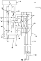
- FIG. 1B is a schematic, perspective view of a drive unit and an attaching device coupled to a robot arm of the medical work station of FIG. 1A ;
- FIG. 2 is a perspective view of an end effector, according to an embodiment of the present disclosure, for use in the medical work station of FIG. 1A , illustrating a jaw assembly thereof in a closed condition;
- FIG. 3 is a perspective view of the end effector of FIG. 2 illustrating the jaw assembly thereof in an open and articulated condition, and illustrating a wrist assembly thereof in an articulated condition;
- FIG. 4A is a flow chart illustrating a method for maintaining predetermined tension on a connector member of a robotic surgical system
- FIG. 4B is a flow chart illustrating a method for determining health of a connector member of a robotic surgical system
- FIG. 5 is a perspective view of another embodiment of an end effector for use in the medical work station of FIG. 1A ;
- FIG. 6A is a perspective view of the end effector of FIG. 5 shown in a straight configuration with jaw members thereof in a closed configuration;
- FIG. 6B is a perspective view of the end effector of FIG. 5 shown in a pitched configuration with the jaw members thereof in the closed configuration;
- FIG. 6C is a perspective view of the end effector of FIG. 5 shown in a yawed configuration with the jaw members thereof in the closed configuration;
- FIG. 6D is a perspective view of the end effector of FIG. 5 shown in the straight configuration with the jaw members thereof in an open configuration;
- FIGS. 7A and 7B are graphical depictions of grasping force data established with respect to the end effector of FIG. 5 .
- a medical work station is shown generally as work station 1 and generally includes a plurality of robot arms 2 , 3 ; a controller/control device 4 ; and an operating console 5 coupled with controller 4 .
- Operating console 5 includes a display device 6 , which is set up in particular to display three-dimensional images; and manual input devices 7 , 8 , by means of which a person (not shown), for example a surgeon, is able to telemanipulate robot arms 2 , 3 in a first operating mode, as known in principle to a person skilled in the art.
- each of robot arms 2 , 3 includes a plurality of members, which are connected through joints, and an attachment device 9 , 11 , to which may be attached, for example, a surgical tool or surgical instrument 20 supporting an end effector 100 .
- Work station 1 is configured for use on a patient 13 lying on a patient table 12 to be treated in a minimally invasive manner by means of end effector 100 .
- Work station 1 may also include more than two robot arms 2 , 3 , the additional robot arms likewise being connected to controller 4 and being telemanipulatable by means of operating console 5 .
- One or more surgical instruments 20 may be attached to the additional robot arm.
- FIG. 1B shows an exemplary attachment device 9 having a drive unit 14 coupled thereto.
- Drive unit 14 and/or attachment device 9 may be directly and/or indirectly attached to, and/or integrally formed with, one of robot arms 2 , 3 .
- drive unit 14 is directly attached to one of robot arms 2 , 3 and attachment device 9 is indirectly attached to one of robot arm 2 , 3 while attachment device 9 is coupled to drive unit 14 .
- attachment device 9 is directly attached to one of the robot arms 2 , 3 and drive unit 14 is indirectly attached to robot arm 2 , 3 while drive unit 14 is coupled to attachment device 9 .
- both attachment device 9 and drive unit 14 are directly attached to one of robot arms 2 , 3 .
- Drive unit 14 includes a drive assembly 15 having one or more motors 16 and one or more drive members 17 coupled to the one or more motors 16 .
- Motor 16 is electrically coupled to controller 4 and operable to impart movement (e.g., rotational movement) to drive member 17 .
- drive member 17 is a lead screw.
- One or more drive tabs 18 are mounted to each drive member 17 and movable there along. As illustrated by arrows “A 1 ,” drive tab 18 is movable relative drive member 17 in an axially direction (e.g., along the z-axis) in response to rotational movement of drive member 17 in clockwise and/or counterclockwise directions as illustrated by arrows “A 2 .”
- drive tab 18 is a split nut drive tab.
- Drive tab 18 may be threadably coupled to drive member 17 to effectuate movement of drive tab 18 relative drive member 17 .
- Drive tab 18 and/or drive member 17 may include any suitable threading configuration.
- one or more of the threads of drive tab 18 and/or drive member 17 can have any suitable shape, diameter, pitch, direction/orientation, etc.
- drive member 17 may include multiple sets of threads, each set of threads being threaded in an opposite direction as compared to an adjacent set of threads.
- each set of threads is configured to engage a different drive tab 18 to impart approximating and/or unapproximating movement between multiple drive tabs 18 .
- Drive tab 18 includes a force sensor 19 a (e.g., a transducer or the like) operatively coupled to controller 4 and configured to determine applied force.
- Drive member 17 supports a position sensor 19 b operatively coupled to controller 4 and configured to determine one or more positions of one or more components (e.g., drive tab 18 ) of drive assembly 15 relative to other components thereof (e.g., drive member 17 ).
- position sensor 19 b is configured to measure a position and/or movement of output of motor 16 , drive member 17 , and/or drive tab 18 .
- Surgical instrument 20 includes one or more instrument tabs 22 movably mounted on one or more supports or rails 24 .
- instrument tab 22 can be axially movable along rails 24 in the z-direction as indicated by arrows “A 3 .”
- One or more connector members 26 are coupled to instrument tab 22 that extend along a shaft assembly 21 of surgical instrument 20 to end effector 100 thereof for effectuating movement of end effector 100 and/or portions thereof in response to movement of the one or more connector members 26 .
- Connector members 26 may include cables, rods, etc. Additionally, and/or alternatively, connector members 26 can be moved for imparting forces to end effector 100 , for example, to fire end effector (e.g., staples, clips, etc.).
- Controller 4 may control current applied to motor 16 during a surgical procedure.
- the current supplied to motor 16 may be adjusted to move drive member 17 and drive tab 18 so that drive tab 18 pushes against and moves a corresponding instrument tab 22 of surgical instrument 20 in the same z-direction to move a component of surgical instrument 20 such as end effector 100 via connector member 26 .
- each connector member 26 in surgical instrument 20 is attached at one end to a respective instrument tab 22 and at an opposite end to a respective portion of end effector 100 .
- Each connector member 26 is connected to a different portion of end effector 100 in order to cause different movements of the end effector 100 (e.g., articulation, rotation, open/close jaw members thereof, etc.) in response to movement of respective instrument tabs 22 via corresponding drive tabs 18 and/or motors 16 of drive unit 14 .
- FIG. 4A A method for maintaining predetermined tension on a connector of a robotic surgical system is shown generally in FIG. 4A .
- the condition of connector member 26 may be measured using data from position sensor 19 b and/or force sensor 19 a .
- motor 16 , drive member 17 , and/or drive tab 18 may be driven into an initial position. This initial position may be referred to a zero position.
- Motor 16 may then be actuated to move the output of motor 16 , drive member 17 , and/or drive tab 18 away from the zero position.
- Position sensor 19 b may measure an amount of movement of the output of motor 16 , drive member 17 , and/or drive tab 18 away from the zero position.
- Position sensor 19 b may continue to measure this movement at least until force measured at force sensor 19 a exceeds a predetermined threshold. When the force measured at force sensor 19 a exceeds a predetermined threshold, a total amount of movement from the zero position may be recorded as a reference condition of connector member 26 .
- the predetermined force threshold may vary in different situations. In some instances, the predetermined force threshold may be a fixed value that is not customized for different applications. In other instances, the predetermined force may vary for different surgical instruments. For example, the predetermined force may be selected to correspond to an amount of force needed to be applied on instrument tab 22 to fully tension connector member 26 without moving a component coupled thereto (such as end effector 100 ). In other instances, different criteria may be used to select the predetermined force.
- the total amount of movement from the zero position may be recorded as an updated condition of connector member 26 .
- the updated condition of connector member 26 may then be compared to the reference condition of connector member 26 to identify a change in the condition of connector member 26 .
- Connector member 26 may stretch out under high tension or otherwise deform over time as connector member 26 is used. As connector member 26 stretches out or otherwise deforms, the distances that drive tab 18 and instrument tab 22 may need to be moved to set a particular connector member 26 tension in connector member 26 corresponding to the predetermined threshold measured at force sensor 19 a may also change. The greater the deformity in connector member 26 , the more drive tab 18 and instrument tab 22 may need to be moved. If the position in the updated condition differs from that in the reference condition by more than a predetermined amount, then different actions may be taken. In some instances, if identified change in the condition of connector member 26 exceeds a threshold then an initial indication may presented to alert a person that connector member 26 may need to be replaced.
- the work station 1 may indicate that the connector member life has been exceeded and/or prevent the use of the surgical instrument 20 containing connector member 26 .
- the updated condition and/or reference condition may be compared to a set of known values to identify an estimated remaining useful life/health of connector member 26 .
- dates that the updated condition and the reference condition were measured along with recorded values of the updated condition and reference condition may be compared to a set of known values to identify an estimated end of life date for replacing connector member 26 .
- different actions and/or two or more of the aforementioned actions may be taken.
- end effector 100 can include a jaw assembly 120 connected to a wrist assembly 110 and one or more connector members 26 for moving (e.g. pivoting/articulating/rotating/opening/closing) jaw assembly 120 about/relative to longitudinal axes such as long axes “X 1 -X 1 ” and/or “X 2 -X 2 ” and/or about/relative to pivot axes such as pivot axes “A-A” and/or “B-B.”
- Wrist assembly 110 couples jaw assembly 120 to a robot arm such as robot arms 2 , 3 .
- connector members 26 In use, as connector members 26 are moved, connector members 26 effect operation and/or movement of each end effector 100 of the surgical instrument (see, e.g., FIGS. 2 and 3 ). It is contemplated that controller 4 activates the various motors 16 to move a respective connector member 26 via tabs 22 in order to coordinate an operation and/or movement of one or more end effectors 100 .
- FIG. 1B shows one end of connector member 26 that is coupled to instrument tab 18 and another end coupled to end effector 100 , in some instances two or more connector members 26 or two ends of a single connector member may be coupled to instrument tab 22 .
- two connector members or connector member ends may be coupled in opposite directions to a single motor so that as the motor is activated in a first direction, one of the connector members winds up while the other connector member lets out.
- Other connector member configurations may be used in different embodiments.
- FIG. 1B shows drive tab 18 engaging with instrument tab 22 only on an upper side of drive tab 18 as drive tab 18 moves up a length of drive member 17
- drive tab 18 may engage with instrument tab 22 on more than one side (e.g., a top and bottom side) and/or instrument tab 22 may engage with drive tab 18 on more than one side. Having at least one of the tabs 18 , 22 engage with the other on more than one side may ensure that the tabs 18 , 22 are locked together so that when drive tab 18 moves up, instrument tab 22 also moves up, and when drive tab 18 moves down, then instrument tab 22 also moves down.
- robot arms 2 , 3 may be driven by electric drives (not shown) that are connected to controller 4 .
- Controller 4 e.g., a computer
- Controller 4 is set up to activate the drives, in particular by means of a computer program, in such a way that robot arms 2 , 3 , their attachment devices 9 , 11 , and thus, surgical instrument 20 (including end effector 100 ) execute a desired movement according to a movement defined by means of manual input devices 7 , 8 .
- Controller 4 may also be set up in such a way that it regulates the movement of robot arms 2 , 3 and/or of the drives.
- Controller 4 can include any suitable logic control circuit adapted to perform calculations and/or operate according to a set of instructions. Controller 4 can be configured to communicate with a remote system “RS,” wirelessly (e.g., Wi-Fi, Bluetooth, LTE, etc.) and/or wired. Remote system “RS” can include data, instructions and/or information related to the various components, algorithms, and/or operations of work station 1 . Remote system “RS” can include any suitable electronic service, database, platform, cloud, or the like. Controller 4 may include a central processing unit operably connected to memory. The memory may include transitory type memory (e.g., RAM) and/or non-transitory type memory (e.g., flash media, disk media, etc.). In some embodiments, the memory is part of, and/or operably coupled to, remote system “RS.”
- a remote system “RS” wirelessly (e.g., Wi-Fi, Bluetooth, LTE, etc.) and/or wired.
- Remote system “RS” can include data, instructions and/or information related
- Controller 4 can include one or more counters to count, for example, a number of uses of one or more of the components of the medical work station (e.g., connector members 26 , end effector 100 , etc.). Controller 4 can include a plurality of inputs and outputs for interfacing with the components of work station 1 , such as through a driver circuit. Controller 4 can be configured to receive input signals and/or generate output signals to control one or more of the various components (e.g., one or more motors 16 ) of work station 1 . The output signals can include, and/or can be based upon, algorithmic instructions which may be pre-programmed and/or input by a user. Controller 4 can be configured to accept a plurality of user inputs from a user interface (e.g., switches, buttons, touch screen, etc. of operating console 5 ) which may be coupled to remote system “RS.”
- a user interface e.g., switches, buttons, touch screen, etc. of operating console 5
- RS remote system
- a database 4 a can be directly and/or indirectly coupled to controller 4 .
- Database 4 a can be configured to store pre-operative data from living being(s) 13 and/or anatomical atlas(es).
- Database 4 a can include memory which can be part of, and/or or operatively coupled to, remote system “RS.”
- the memory of database 4 a includes reference data of one or more of any of the components of work station 1 .
- the reference data can be predetermined.
- the reference data can be measured, created, or stored in real-time.
- the reference data can include any suitable property, characteristic and/or condition of one or more of the components of work station 1 .
- the memory can include tensile data of the one or more connector members 26 such as connector member strength, elasticity, and/or degradation data applicable to one or more of connector members 26 , a number of uses of one or more of connector members 26 , and/or an age of one or more of connector members 26 .
- the reference data may include ranges or sets of ranges to which real-time data can be compared and contrasted for determining health (e.g., expended and/or remaining lifespan).
- the memory of database 4 a may also store a connector member reference condition, one or more updated connector member conditions, and/or other data associated with the stored conditions, such as a date that the condition was measured, created, or stored.
- the work station 1 may support one or more position sensors 19 b and force sensors 19 a that may be in electrical communication with controller 4 and/or remote system “RS.”
- the sensors 19 a , 19 b may be configured to provide an input signal indicative of real-time position and force data to controller 4 .
- Force sensor 19 a may include a strain gauge load cell and/or a piezoelectric load cell.
- Position sensor 19 b may include an absolute or incremental position sensor. In some instances, where positional sensor is configured to measure position information of a rotating object, such as drive member 17 and/or a shaft output of motor 16 , position sensor 19 b may include a rotary encoder or other sensor that converts an angular position or motion of a rotating output to an analog or digital code.
- Sensors 19 a , 19 b may be configured to measure, sample, and/or transmit positional or force information in real-time at similar intervals so that the data from each of the sensors 19 a , 19 b coincides with each other.
- Controller 4 can be programmed to compare real-time data to reference data and provide an output signal in response to a comparison of the real-time data to the reference data.
- controller 4 can be configured to communicate with one or more of the motors 16 to adjust the position of tabs 18 , 22 , and/or an amount of tension in one or more of connector members 26 in response to the output signal.
- controller 4 may be configured to check whether connector members 26 in surgical instrument 20 , are associated with any previously stored reference conditions while surgical instrument 20 is coupled to one of robot arm 2 , 3 . Controller 4 may then be configured to retrieve the reference conditions form a memory to the extent that such as association exists, otherwise controller 4 may be configured to trigger one or more of the aforementioned procedures to generate and then store the reference condition.
- controller 4 may be configured to further trigger, in response to one or more events, one or more of the aforementioned procedures to generate and/or store an updated condition of connector member 26 .
- events can include, for example, an initial and/or subsequent coupling of the surgical instrument 20 to the robot arm 2 , 3 ; a use count of the surgical instrument 20 that exceeds a threshold value; a user initiated command; and/or an expiration of one or more time periods.
- referenced data/information of the components of work station 1 can be stored in memory, for example, on a memory device coupled to medical work station 1 and/or part of remote system “RS” as described above. Such data/information can be stored prior to any use of one or more components of work station 1 .
- One or more first events such as those described above (e.g., generating and storing a reference or update condition, a use and/or a number of uses of one or more connector members 26 ), can occur so that real-time data of components of the work station 1 can be measured. Measurement of the real-time data can be determined by virtue of force and position sensors 19 a , 19 b and/or controller 4 , prior to a use of one or more of the components.
- reference data of the one or more connector members 26 can be compared with measured real-time data of the one or more connector members 26 to determine the real-time health (e.g., remaining/expended lifespan) of one or more connector members 26 relative to the initial health of one or more connector members 26 . If lifespan/health of one or more of connector members 26 remains or is intact, an output signal may be provided. An occurrence of another event, which may be different and/or the same as the one or more first events, may also provide an output signal.
- the real-time health e.g., remaining/expended lifespan
- the output signal can be any suitable signal, for example, indicative of health/remaining lifespan (e.g., via number of uses, time period, etc.), if any, and/or failure.
- An output signal indicative of failure can be generated by controller 4 upon a breaking of one or more of connector members 26 , or upon a lengthening of the one or more connector members 26 beyond predetermined amount.
- stored pre-determined data may be preset and/or updated periodically, including before, during, and/or after use.
- controller 4 can be configured to generate/analyze force versus position plots to approximate a degradation of connector member 26 .
- the method may include initially calibrating a reference condition in connector member 26 , but in other instances this feature may have been previously performed, calculated, or estimated.
- the method can include measuring the real-time data of the one or more connector members 26 after one or more uses thereof.
- the method involves automating an output signal indicative of real-time data of the one or more connector members 26 in response to one or more events.
- the one or more events can include a first use of the surgical tool, a use of the surgical tool subsequent to the first use of the surgical tool, and/or an expiration of one or more time periods.
- the method may include receiving an input signal, indicative of a user input, as an event to initiate an output signal indicative of real-time data of the one or more connector members 26 .
- the method can involve registering a failure of the one or more connector members 26 and providing an output signal indicative of the failure.
- End effector 200 is a wristed surgical device that uses differential cable tension on four connector member ends 230 a - 230 d of a pair of connector members 231 a , 231 b to drive three primary motion outputs: yawing movement, illustrated by arrow “Y,” pitching movement, illustrated by arrow “P,” and grasping movement, illustrated by arrow “J.”
- End effector 200 includes a mounting member or wrist assembly 210 , a jaw assembly 220 , a connector member assembly 230 , and a clevis 240 that are operatively coupled to medical work station 1 .
- Wrist assembly 210 which may form part of shaft assembly 21 of surgical instrument 20 , has a mount body 210 a with a proximal end that couples to surgical instrument 20 ( FIG. 1B ).
- Mount body 210 a extends distally to a pair of spaced-apart arms including a first arm 210 b and a second arm 210 c .
- the pair of spaced-apart arms defines a first pin channel 210 d and a second pin channel 210 e that extend transversely through each of first and second arms 210 b , 210 c .
- Wrist assembly 210 supports a first set of idler pulleys 212 and a second set of idler pulleys 214 that are aligned with first and second pin channels 210 d , 210 e , respectively, such that the first set of idler pulleys 212 is located proximal of second set of idler pulleys 214 .
- First and second sets of idler pulleys 212 , 214 are secured to wrist assembly 210 via first and second pulley pins 250 a , 250 b , respectively.
- Second pulley pin 250 b and second set of idler pulleys 214 define a pitch axis “C 1 ” about which first and second jaw members 222 , 224 pitch relative to longitudinal axis “L.”
- Jaw assembly 220 includes a first jaw member 222 and a second jaw member 224 that are pivotably coupled together.
- First jaw member 222 includes a grasping portion 222 a that extends distally from a jaw pulley 222 b .
- Second jaw member 224 includes a grasping portion 224 a that extends distally from a jaw pulley 224 b .
- First and second jaw pulleys 222 b , 224 b may be integrally formed with grasping portions 222 a , 224 a , respectively.
- Grasping portions 222 a , 224 a include respective tissue-engaging surfaces 222 c , 224 c configured to engage tissue.
- First and second jaw pulleys 222 b , 224 b define respective first and second connector member channels 222 d , 224 d configured to receive connector member assembly 230 .
- Connector member assembly 230 includes a pair of connector members 231 a , 231 b that are routed/wrapped around the sets of idler pulleys 212 , 214 and jaw pulleys 222 b , 224 b to a plurality of connector member portions 230 a - 230 d .
- First connector member 231 a of the pair of connector members 231 a , 231 b includes a first connector member portion 230 a of the plurality of connector member portions 230 a - 230 d at one end thereof and a second connector member portion 230 c of the plurality of connector member portions 230 a - 230 d at a second end thereof.
- Second connector member 231 b of the pair of connector members 231 a , 231 b includes a third connector member portion 230 b of the plurality of connector member portions 230 a - 230 d at a first end thereof and a fourth connector member portion 230 d of the plurality of connector member portions 230 a - 230 d at a second end thereof.
- a plurality of ferrules 232 are coupled to the pair of connector members 231 a , 231 b to secure the pair of connector members 231 a , 231 b to first and second jaw members 222 , 224 of jaw assembly 220 , respectively.
- first connector member 231 a is secured to jaw pulley 222 b of first jaw member 222 by first one of the pair of ferrules 232 and a central portion of second connector member 231 b is secured to jaw pulley 224 b of second jaw member 224 by a second one of the pair of ferrules 232 .
- Proximal ends of cable member portions 230 a - 230 d are coupled to one or more instrument tabs 22 of surgical instrument 22 so that connector member portions 230 a - 230 d move in response to movement of the instrument tabs 22 as described above.
- one or more of connector member portions 230 a - 230 d can be moved independently of one or more of the other connector member portions 230 a - 230 d and/or simultaneously with one or more of the other connector member portions 230 a - 230 d in the same and/or in opposite directions of one or more of the other connector member portions 230 a - 230 d to effectuate pitching, yawing, and/or opening/closing of jaw assembly 220 .
- clevis 240 includes a pair of fingers 242 , 244 that extend from a base portion 246 .
- Each of the pair of fingers 242 , 244 is spaced apart from the other and together, the pair of fingers 242 , 244 defines a pin passage 242 a that extends therethrough.
- the base portion 246 is pivotally mounted to second set of idler pulleys 214 by pivot pin 250 b to enable jaw assembly 220 to pitch/articulate, as indicated by arrow “P,” relative to a longitudinal axis “L” of end effector 200 .
- Jaw pulleys 222 b , 224 b of jaw assembly 220 are coupled together and mounted between the pair of fingers 242 , 244 of clevis 240 by pivot pin 250 c .
- Pivot pin 250 c and jaw pulleys 222 b , 224 b of jaw assembly 220 define yaw and grasping axes “C 2 ” and “C 3 ,” respectively, which are coincident with each other.
- Pin passage 242 a receives pivot pin 250 c to enable jaw assembly 220 to yaw about yaw axis “C 2 ” relative to a longitudinal axis “L” of end effector 200 , as indicated by arrow “Y,” and/or open/close jaw assembly 220 , about grasping axis “C 3 ” as indicated by arrow “J.”
- wrist length is minimized, enabling greater pitch and/or yaw movement while minimizing shaft motion, which, in turn, enables multiple instruments to be placed closer together and/or enables faster manipulation of the end effector.
- the pair of connector members 231 a , 231 b namely the plurality of connector member portions 230 a - 230 d can be pulled and/or released by movement of instrument tabs 22 , described above, to achieve pitch, yaw, grasping/dissecting and/or any combinations of these motions.
- This differential drive arrangement advantageously enables the tension in the pair of connector members 231 a , 231 b to be adjusted and/or relaxed as desired, for example, to limit load applied to various components of the surgical system (e.g., connector members, pulleys, tabs, etc.).
- position and/or force sensors 19 a , 19 b can be utilized to actively monitor output loads, such as grasping force, torque around the pitch axis, and torque around the yaw axis.
- the test rig included a custom jaw set of 17-4 H900 Direct Metal Laser sintered (DMLS) jaws with a load cell at the tip thereof to evaluate the feasibility of using connector member tensions of full length tungsten connector members to estimate tip grasping forces “F.”
- Each jaw member of the jaw set included a jaw pulley. Each jaw pulley had the same radius.
- FIG. 7A To simulate the presence of an external force, Jaw 1 and Jaw 2 were driven into each other to develop force data with respect to only the grasp (see FIG. 7A ) and with respect to combined grasp and movement (see FIG. 7B ).
- FIGS. 7A and 7B After running cyclic tests while varying jaw, pitch, and yaw angles, the results were then plotted on a graph with respect to the calculated forces. Negative jaw angles indicated jaw overlap: the greater the negative value, the higher the simulated force.
- FIG. 7B the graph indicates that the calculated grasping force tracts the measured jaw force with an increase in the grasping force as the jaw angle is decreased.
- Jaw1Force Jaw2Force
- Jaw1Force F+f when Jaw1 is driven into Jaw2
- Jaw1Force F ⁇ f when Jaw1 is in contact with Jaw2 and is driven away from Jaw2
- Jaw2Force F+f when Jaw2 is driven into Jaw1
- Jaw2Force F ⁇ f when Jaw2 is in contact with Jaw1 and is driven away from Jaw1
Abstract
Description
force of first jaw member (“Jaw1”) of the jaw set (“Jaw1Force”)=[(T3−T1)×radius of one of the jaw pulleys]/length of one of the jaw members;
force of second jaw member (“Jaw2”) of the jaw set (“Jaw2Force”)=[(T4−T2)×radius of one of the jaw pulleys]/length of one of the jaw members; and
calculated force=[Jaw1Force+Jaw2Force]/2;
where T1−T4 correspond to tension applied to
Jaw1Force=Jaw2Force
In the presence of friction:
Jaw1Force=F+f when Jaw1 is driven into Jaw2 BUT
Jaw1Force=F−f when Jaw1 is in contact with Jaw2 and is driven away from Jaw2
Similarly,
Jaw2Force=F+f when Jaw2 is driven into Jaw1 BUT
Jaw2Force=F−f when Jaw2 is in contact with Jaw1 and is driven away from Jaw1
Where the combination of yaw motion along with jaw closing causes
Jaw1Force=F+f and Jaw2Force=F−f
Computed Force=(Jaw1Force+Jaw2Force)/2=(F+f+F−f)/2=F
The error in measurement occurs when both Jaw1 and Jaw2 are moving towards each other or away from each other. The error is +/−f. This 2 f range of error can be observed in the plotted data as the difference between the observed and the measure (Max 3 N).
Claims (7)
Priority Applications (1)
| Application Number | Priority Date | Filing Date | Title |
|---|---|---|---|
| US15/548,866 US10716639B2 (en) | 2015-03-10 | 2016-03-08 | Measuring health of a connector member of a robotic surgical system |
Applications Claiming Priority (4)
| Application Number | Priority Date | Filing Date | Title |
|---|---|---|---|
| US201562130672P | 2015-03-10 | 2015-03-10 | |
| US201562184305P | 2015-06-25 | 2015-06-25 | |
| US15/548,866 US10716639B2 (en) | 2015-03-10 | 2016-03-08 | Measuring health of a connector member of a robotic surgical system |
| PCT/US2016/021331 WO2016144937A1 (en) | 2015-03-10 | 2016-03-08 | Measuring health of a connector member of a robotic surgical system |
Related Parent Applications (1)
| Application Number | Title | Priority Date | Filing Date |
|---|---|---|---|
| PCT/US2016/021331 A-371-Of-International WO2016144937A1 (en) | 2015-03-10 | 2016-03-08 | Measuring health of a connector member of a robotic surgical system |
Related Child Applications (1)
| Application Number | Title | Priority Date | Filing Date |
|---|---|---|---|
| US16/868,735 Continuation US11596489B2 (en) | 2015-03-10 | 2020-05-07 | Measuring health of a connector member of a robotic surgical system |
Publications (2)
| Publication Number | Publication Date |
|---|---|
| US20180064498A1 US20180064498A1 (en) | 2018-03-08 |
| US10716639B2 true US10716639B2 (en) | 2020-07-21 |
Family
ID=56879726
Family Applications (2)
| Application Number | Title | Priority Date | Filing Date |
|---|---|---|---|
| US15/548,866 Active 2036-09-15 US10716639B2 (en) | 2015-03-10 | 2016-03-08 | Measuring health of a connector member of a robotic surgical system |
| US16/868,735 Active 2036-11-06 US11596489B2 (en) | 2015-03-10 | 2020-05-07 | Measuring health of a connector member of a robotic surgical system |
Family Applications After (1)
| Application Number | Title | Priority Date | Filing Date |
|---|---|---|---|
| US16/868,735 Active 2036-11-06 US11596489B2 (en) | 2015-03-10 | 2020-05-07 | Measuring health of a connector member of a robotic surgical system |
Country Status (7)
| Country | Link |
|---|---|
| US (2) | US10716639B2 (en) |
| EP (1) | EP3267920A4 (en) |
| JP (2) | JP2018507727A (en) |
| CN (2) | CN113040921A (en) |
| AU (2) | AU2016229897B2 (en) |
| CA (1) | CA2977413A1 (en) |
| WO (1) | WO2016144937A1 (en) |
Cited By (114)
| Publication number | Priority date | Publication date | Assignee | Title |
|---|---|---|---|---|
| US10892899B2 (en) | 2017-12-28 | 2021-01-12 | Ethicon Llc | Self describing data packets generated at an issuing instrument |
| US10892995B2 (en) | 2017-12-28 | 2021-01-12 | Ethicon Llc | Surgical network determination of prioritization of communication, interaction, or processing based on system or device needs |
| US10898622B2 (en) | 2017-12-28 | 2021-01-26 | Ethicon Llc | Surgical evacuation system with a communication circuit for communication between a filter and a smoke evacuation device |
| US10932806B2 (en) | 2017-10-30 | 2021-03-02 | Ethicon Llc | Reactive algorithm for surgical system |
| US10932872B2 (en) | 2017-12-28 | 2021-03-02 | Ethicon Llc | Cloud-based medical analytics for linking of local usage trends with the resource acquisition behaviors of larger data set |
| US10966791B2 (en) | 2017-12-28 | 2021-04-06 | Ethicon Llc | Cloud-based medical analytics for medical facility segmented individualization of instrument function |
| US10973520B2 (en) | 2018-03-28 | 2021-04-13 | Ethicon Llc | Surgical staple cartridge with firing member driven camming assembly that has an onboard tissue cutting feature |
| US10987178B2 (en) | 2017-12-28 | 2021-04-27 | Ethicon Llc | Surgical hub control arrangements |
| US11013569B2 (en) | 2019-06-27 | 2021-05-25 | Cilag Gmbh International | Surgical systems with interchangeable motor packs |
| US11026751B2 (en) | 2017-12-28 | 2021-06-08 | Cilag Gmbh International | Display of alignment of staple cartridge to prior linear staple line |
| US11026687B2 (en) | 2017-10-30 | 2021-06-08 | Cilag Gmbh International | Clip applier comprising clip advancing systems |
| US11056244B2 (en) | 2017-12-28 | 2021-07-06 | Cilag Gmbh International | Automated data scaling, alignment, and organizing based on predefined parameters within surgical networks |
| US11058498B2 (en) | 2017-12-28 | 2021-07-13 | Cilag Gmbh International | Cooperative surgical actions for robot-assisted surgical platforms |
| US11090047B2 (en) | 2018-03-28 | 2021-08-17 | Cilag Gmbh International | Surgical instrument comprising an adaptive control system |
| US11096688B2 (en) | 2018-03-28 | 2021-08-24 | Cilag Gmbh International | Rotary driven firing members with different anvil and channel engagement features |
| US11100631B2 (en) | 2017-12-28 | 2021-08-24 | Cilag Gmbh International | Use of laser light and red-green-blue coloration to determine properties of back scattered light |
| US11096693B2 (en) | 2017-12-28 | 2021-08-24 | Cilag Gmbh International | Adjustment of staple height of at least one row of staples based on the sensed tissue thickness or force in closing |
| US11109866B2 (en) | 2017-12-28 | 2021-09-07 | Cilag Gmbh International | Method for circular stapler control algorithm adjustment based on situational awareness |
| US11114195B2 (en) | 2017-12-28 | 2021-09-07 | Cilag Gmbh International | Surgical instrument with a tissue marking assembly |
| US11129611B2 (en) | 2018-03-28 | 2021-09-28 | Cilag Gmbh International | Surgical staplers with arrangements for maintaining a firing member thereof in a locked configuration unless a compatible cartridge has been installed therein |
| US11147607B2 (en) | 2017-12-28 | 2021-10-19 | Cilag Gmbh International | Bipolar combination device that automatically adjusts pressure based on energy modality |
| US11179204B2 (en) | 2017-12-28 | 2021-11-23 | Cilag Gmbh International | Wireless pairing of a surgical device with another device within a sterile surgical field based on the usage and situational awareness of devices |
| US11179175B2 (en) | 2017-12-28 | 2021-11-23 | Cilag Gmbh International | Controlling an ultrasonic surgical instrument according to tissue location |
| US11207146B2 (en) | 2019-06-27 | 2021-12-28 | Cilag Gmbh International | Surgical instrument drive systems with cable-tightening system |
| US11207067B2 (en) | 2018-03-28 | 2021-12-28 | Cilag Gmbh International | Surgical stapling device with separate rotary driven closure and firing systems and firing member that engages both jaws while firing |
| US11219453B2 (en) | 2018-03-28 | 2022-01-11 | Cilag Gmbh International | Surgical stapling devices with cartridge compatible closure and firing lockout arrangements |
| US11229436B2 (en) | 2017-10-30 | 2022-01-25 | Cilag Gmbh International | Surgical system comprising a surgical tool and a surgical hub |
| US11234756B2 (en) | 2017-12-28 | 2022-02-01 | Cilag Gmbh International | Powered surgical tool with predefined adjustable control algorithm for controlling end effector parameter |
| US11257589B2 (en) | 2017-12-28 | 2022-02-22 | Cilag Gmbh International | Real-time analysis of comprehensive cost of all instrumentation used in surgery utilizing data fluidity to track instruments through stocking and in-house processes |
| US11253315B2 (en) | 2017-12-28 | 2022-02-22 | Cilag Gmbh International | Increasing radio frequency to create pad-less monopolar loop |
| US11259806B2 (en) | 2018-03-28 | 2022-03-01 | Cilag Gmbh International | Surgical stapling devices with features for blocking advancement of a camming assembly of an incompatible cartridge installed therein |
| US11259807B2 (en) | 2019-02-19 | 2022-03-01 | Cilag Gmbh International | Staple cartridges with cam surfaces configured to engage primary and secondary portions of a lockout of a surgical stapling device |
| US11259830B2 (en) | 2018-03-08 | 2022-03-01 | Cilag Gmbh International | Methods for controlling temperature in ultrasonic device |
| US11273001B2 (en) | 2017-12-28 | 2022-03-15 | Cilag Gmbh International | Surgical hub and modular device response adjustment based on situational awareness |
| US11278280B2 (en) | 2018-03-28 | 2022-03-22 | Cilag Gmbh International | Surgical instrument comprising a jaw closure lockout |
| US11278362B2 (en) | 2019-06-27 | 2022-03-22 | Cilag Gmbh International | Surgical instrument drive systems |
| US11278281B2 (en) | 2017-12-28 | 2022-03-22 | Cilag Gmbh International | Interactive surgical system |
| US11284936B2 (en) | 2017-12-28 | 2022-03-29 | Cilag Gmbh International | Surgical instrument having a flexible electrode |
| US11291495B2 (en) | 2017-12-28 | 2022-04-05 | Cilag Gmbh International | Interruption of energy due to inadvertent capacitive coupling |
| US11291510B2 (en) | 2017-10-30 | 2022-04-05 | Cilag Gmbh International | Method of hub communication with surgical instrument systems |
| US11298148B2 (en) | 2018-03-08 | 2022-04-12 | Cilag Gmbh International | Live time tissue classification using electrical parameters |
| US11304720B2 (en) | 2017-12-28 | 2022-04-19 | Cilag Gmbh International | Activation of energy devices |
| US11304699B2 (en) | 2017-12-28 | 2022-04-19 | Cilag Gmbh International | Method for adaptive control schemes for surgical network control and interaction |
| US11308075B2 (en) | 2017-12-28 | 2022-04-19 | Cilag Gmbh International | Surgical network, instrument, and cloud responses based on validation of received dataset and authentication of its source and integrity |
| US11304763B2 (en) | 2017-12-28 | 2022-04-19 | Cilag Gmbh International | Image capturing of the areas outside the abdomen to improve placement and control of a surgical device in use |
| US11311306B2 (en) | 2017-12-28 | 2022-04-26 | Cilag Gmbh International | Surgical systems for detecting end effector tissue distribution irregularities |
| US11311342B2 (en) | 2017-10-30 | 2022-04-26 | Cilag Gmbh International | Method for communicating with surgical instrument systems |
| US11317919B2 (en) | 2017-10-30 | 2022-05-03 | Cilag Gmbh International | Clip applier comprising a clip crimping system |
| US11317937B2 (en) | 2018-03-08 | 2022-05-03 | Cilag Gmbh International | Determining the state of an ultrasonic end effector |
| US11317915B2 (en) | 2019-02-19 | 2022-05-03 | Cilag Gmbh International | Universal cartridge based key feature that unlocks multiple lockout arrangements in different surgical staplers |
| USD950728S1 (en) | 2019-06-25 | 2022-05-03 | Cilag Gmbh International | Surgical staple cartridge |
| US11324557B2 (en) | 2017-12-28 | 2022-05-10 | Cilag Gmbh International | Surgical instrument with a sensing array |
| USD952144S1 (en) | 2019-06-25 | 2022-05-17 | Cilag Gmbh International | Surgical staple cartridge retainer with firing system authentication key |
| US11337746B2 (en) | 2018-03-08 | 2022-05-24 | Cilag Gmbh International | Smart blade and power pulsing |
| US11357503B2 (en) | 2019-02-19 | 2022-06-14 | Cilag Gmbh International | Staple cartridge retainers with frangible retention features and methods of using same |
| US11364075B2 (en) | 2017-12-28 | 2022-06-21 | Cilag Gmbh International | Radio frequency energy device for delivering combined electrical signals |
| US11369377B2 (en) | 2019-02-19 | 2022-06-28 | Cilag Gmbh International | Surgical stapling assembly with cartridge based retainer configured to unlock a firing lockout |
| US11369443B2 (en) | 2019-06-27 | 2022-06-28 | Cilag Gmbh International | Method of using a surgical modular robotic assembly |
| US11376002B2 (en) | 2017-12-28 | 2022-07-05 | Cilag Gmbh International | Surgical instrument cartridge sensor assemblies |
| US11376083B2 (en) | 2019-06-27 | 2022-07-05 | Cilag Gmbh International | Determining robotic surgical assembly coupling status |
| US11376082B2 (en) | 2019-06-27 | 2022-07-05 | Cilag Gmbh International | Robotic surgical system with local sensing of functional parameters based on measurements of multiple physical inputs |
| US11389164B2 (en) | 2017-12-28 | 2022-07-19 | Cilag Gmbh International | Method of using reinforced flexible circuits with multiple sensors to optimize performance of radio frequency devices |
| US11399906B2 (en) | 2019-06-27 | 2022-08-02 | Cilag Gmbh International | Robotic surgical system for controlling close operation of end-effectors |
| US11413102B2 (en) | 2019-06-27 | 2022-08-16 | Cilag Gmbh International | Multi-access port for surgical robotic systems |
| US11423007B2 (en) | 2017-12-28 | 2022-08-23 | Cilag Gmbh International | Adjustment of device control programs based on stratified contextual data in addition to the data |
| US11419630B2 (en) | 2017-12-28 | 2022-08-23 | Cilag Gmbh International | Surgical system distributed processing |
| US11419667B2 (en) | 2017-12-28 | 2022-08-23 | Cilag Gmbh International | Ultrasonic energy device which varies pressure applied by clamp arm to provide threshold control pressure at a cut progression location |
| US11446052B2 (en) | 2017-12-28 | 2022-09-20 | Cilag Gmbh International | Variation of radio frequency and ultrasonic power level in cooperation with varying clamp arm pressure to achieve predefined heat flux or power applied to tissue |
| USD964564S1 (en) | 2019-06-25 | 2022-09-20 | Cilag Gmbh International | Surgical staple cartridge retainer with a closure system authentication key |
| US11464535B2 (en) | 2017-12-28 | 2022-10-11 | Cilag Gmbh International | Detection of end effector emersion in liquid |
| US11464559B2 (en) | 2017-12-28 | 2022-10-11 | Cilag Gmbh International | Estimating state of ultrasonic end effector and control system therefor |
| US11464511B2 (en) | 2019-02-19 | 2022-10-11 | Cilag Gmbh International | Surgical staple cartridges with movable authentication key arrangements |
| US11471156B2 (en) | 2018-03-28 | 2022-10-18 | Cilag Gmbh International | Surgical stapling devices with improved rotary driven closure systems |
| US11504192B2 (en) | 2014-10-30 | 2022-11-22 | Cilag Gmbh International | Method of hub communication with surgical instrument systems |
| US11510741B2 (en) | 2017-10-30 | 2022-11-29 | Cilag Gmbh International | Method for producing a surgical instrument comprising a smart electrical system |
| US11540855B2 (en) | 2017-12-28 | 2023-01-03 | Cilag Gmbh International | Controlling activation of an ultrasonic surgical instrument according to the presence of tissue |
| US11547468B2 (en) | 2019-06-27 | 2023-01-10 | Cilag Gmbh International | Robotic surgical system with safety and cooperative sensing control |
| US11547465B2 (en) | 2012-06-28 | 2023-01-10 | Cilag Gmbh International | Surgical end effector jaw and electrode configurations |
| US11559308B2 (en) | 2017-12-28 | 2023-01-24 | Cilag Gmbh International | Method for smart energy device infrastructure |
| US11559307B2 (en) | 2017-12-28 | 2023-01-24 | Cilag Gmbh International | Method of robotic hub communication, detection, and control |
| US11564756B2 (en) | 2017-10-30 | 2023-01-31 | Cilag Gmbh International | Method of hub communication with surgical instrument systems |
| US11571234B2 (en) | 2017-12-28 | 2023-02-07 | Cilag Gmbh International | Temperature control of ultrasonic end effector and control system therefor |
| US11576677B2 (en) | 2017-12-28 | 2023-02-14 | Cilag Gmbh International | Method of hub communication, processing, display, and cloud analytics |
| US11589932B2 (en) | 2017-12-28 | 2023-02-28 | Cilag Gmbh International | Usage and technique analysis of surgeon / staff performance against a baseline to optimize device utilization and performance for both current and future procedures |
| US11589888B2 (en) | 2017-12-28 | 2023-02-28 | Cilag Gmbh International | Method for controlling smart energy devices |
| US11596291B2 (en) | 2017-12-28 | 2023-03-07 | Cilag Gmbh International | Method of compressing tissue within a stapling device and simultaneously displaying of the location of the tissue within the jaws |
| US11602393B2 (en) | 2017-12-28 | 2023-03-14 | Cilag Gmbh International | Surgical evacuation sensing and generator control |
| US11607278B2 (en) | 2019-06-27 | 2023-03-21 | Cilag Gmbh International | Cooperative robotic surgical systems |
| US11612444B2 (en) | 2017-12-28 | 2023-03-28 | Cilag Gmbh International | Adjustment of a surgical device function based on situational awareness |
| US11612445B2 (en) | 2019-06-27 | 2023-03-28 | Cilag Gmbh International | Cooperative operation of robotic arms |
| US11659023B2 (en) | 2017-12-28 | 2023-05-23 | Cilag Gmbh International | Method of hub communication |
| US11666331B2 (en) | 2017-12-28 | 2023-06-06 | Cilag Gmbh International | Systems for detecting proximity of surgical end effector to cancerous tissue |
| US11696760B2 (en) | 2017-12-28 | 2023-07-11 | Cilag Gmbh International | Safety systems for smart powered surgical stapling |
| US11723729B2 (en) | 2019-06-27 | 2023-08-15 | Cilag Gmbh International | Robotic surgical assembly coupling safety mechanisms |
| US11737668B2 (en) | 2017-12-28 | 2023-08-29 | Cilag Gmbh International | Communication hub and storage device for storing parameters and status of a surgical device to be shared with cloud based analytics systems |
| US11744604B2 (en) | 2017-12-28 | 2023-09-05 | Cilag Gmbh International | Surgical instrument with a hardware-only control circuit |
| US11751958B2 (en) | 2017-12-28 | 2023-09-12 | Cilag Gmbh International | Surgical hub coordination of control and communication of operating room devices |
| US11771487B2 (en) | 2017-12-28 | 2023-10-03 | Cilag Gmbh International | Mechanisms for controlling different electromechanical systems of an electrosurgical instrument |
| US11775682B2 (en) | 2017-12-28 | 2023-10-03 | Cilag Gmbh International | Data stripping method to interrogate patient records and create anonymized record |
| US11786251B2 (en) | 2017-12-28 | 2023-10-17 | Cilag Gmbh International | Method for adaptive control schemes for surgical network control and interaction |
| US11786245B2 (en) | 2017-12-28 | 2023-10-17 | Cilag Gmbh International | Surgical systems with prioritized data transmission capabilities |
| US11801098B2 (en) | 2017-10-30 | 2023-10-31 | Cilag Gmbh International | Method of hub communication with surgical instrument systems |
| US11818052B2 (en) | 2017-12-28 | 2023-11-14 | Cilag Gmbh International | Surgical network determination of prioritization of communication, interaction, or processing based on system or device needs |
| US11832840B2 (en) | 2017-12-28 | 2023-12-05 | Cilag Gmbh International | Surgical instrument having a flexible circuit |
| US11832899B2 (en) | 2017-12-28 | 2023-12-05 | Cilag Gmbh International | Surgical systems with autonomously adjustable control programs |
| US11864728B2 (en) | 2017-12-28 | 2024-01-09 | Cilag Gmbh International | Characterization of tissue irregularities through the use of mono-chromatic light refractivity |
| US11871901B2 (en) | 2012-05-20 | 2024-01-16 | Cilag Gmbh International | Method for situational awareness for surgical network or surgical network connected device capable of adjusting function based on a sensed situation or usage |
| US11890065B2 (en) | 2017-12-28 | 2024-02-06 | Cilag Gmbh International | Surgical system to limit displacement |
| US11896322B2 (en) | 2017-12-28 | 2024-02-13 | Cilag Gmbh International | Sensing the patient position and contact utilizing the mono-polar return pad electrode to provide situational awareness to the hub |
| US11896443B2 (en) | 2017-12-28 | 2024-02-13 | Cilag Gmbh International | Control of a surgical system through a surgical barrier |
| US11903601B2 (en) | 2017-12-28 | 2024-02-20 | Cilag Gmbh International | Surgical instrument comprising a plurality of drive systems |
| US11911045B2 (en) | 2017-10-30 | 2024-02-27 | Cllag GmbH International | Method for operating a powered articulating multi-clip applier |
| US11931026B2 (en) | 2021-06-30 | 2024-03-19 | Cilag Gmbh International | Staple cartridge replacement |
| US11937769B2 (en) | 2017-12-28 | 2024-03-26 | Cilag Gmbh International | Method of hub communication, processing, storage and display |
Families Citing this family (58)
| Publication number | Priority date | Publication date | Assignee | Title |
|---|---|---|---|---|
| EP2923669B1 (en) | 2014-03-24 | 2017-06-28 | Hansen Medical, Inc. | Systems and devices for catheter driving instinctiveness |
| US9737371B2 (en) | 2014-09-30 | 2017-08-22 | Auris Surgical Robotics, Inc. | Configurable robotic surgical system with virtual rail and flexible endoscope |
| US10314463B2 (en) | 2014-10-24 | 2019-06-11 | Auris Health, Inc. | Automated endoscope calibration |
| CA2996698C (en) * | 2015-08-26 | 2021-07-13 | Berkshire Grey, Inc. | Systems and methods for providing contact detection in an articulated arm |
| ITUB20154977A1 (en) | 2015-10-16 | 2017-04-16 | Medical Microinstruments S R L | Medical instrument and method of manufacture of said medical instrument |
| US9931025B1 (en) * | 2016-09-30 | 2018-04-03 | Auris Surgical Robotics, Inc. | Automated calibration of endoscopes with pull wires |
| US10244926B2 (en) | 2016-12-28 | 2019-04-02 | Auris Health, Inc. | Detecting endolumenal buckling of flexible instruments |
| US11529129B2 (en) | 2017-05-12 | 2022-12-20 | Auris Health, Inc. | Biopsy apparatus and system |
| WO2019005872A1 (en) | 2017-06-28 | 2019-01-03 | Auris Health, Inc. | Instrument insertion compensation |
| US10426559B2 (en) | 2017-06-30 | 2019-10-01 | Auris Health, Inc. | Systems and methods for medical instrument compression compensation |
| US10145747B1 (en) | 2017-10-10 | 2018-12-04 | Auris Health, Inc. | Detection of undesirable forces on a surgical robotic arm |
| US10786320B2 (en) * | 2017-10-26 | 2020-09-29 | Ethicon Llc | Cable driven motion systems for robotic surgical tools |
| EP3684282B1 (en) | 2017-12-06 | 2024-02-21 | Auris Health, Inc. | Systems to correct for uncommanded instrument roll |
| US11510736B2 (en) | 2017-12-14 | 2022-11-29 | Auris Health, Inc. | System and method for estimating instrument location |
| US10849697B2 (en) | 2017-12-28 | 2020-12-01 | Ethicon Llc | Cloud interface for coupled surgical devices |
| US11857152B2 (en) | 2017-12-28 | 2024-01-02 | Cilag Gmbh International | Surgical hub spatial awareness to determine devices in operating theater |
| US11266468B2 (en) | 2017-12-28 | 2022-03-08 | Cilag Gmbh International | Cooperative utilization of data derived from secondary sources by intelligent surgical hubs |
| US11304745B2 (en) | 2017-12-28 | 2022-04-19 | Cilag Gmbh International | Surgical evacuation sensing and display |
| US10695081B2 (en) | 2017-12-28 | 2020-06-30 | Ethicon Llc | Controlling a surgical instrument according to sensed closure parameters |
| US11529187B2 (en) | 2017-12-28 | 2022-12-20 | Cilag Gmbh International | Surgical evacuation sensor arrangements |
| US11179208B2 (en) | 2017-12-28 | 2021-11-23 | Cilag Gmbh International | Cloud-based medical analytics for security and authentication trends and reactive measures |
| US11069012B2 (en) | 2017-12-28 | 2021-07-20 | Cilag Gmbh International | Interactive surgical systems with condition handling of devices and data capabilities |
| US11051876B2 (en) | 2017-12-28 | 2021-07-06 | Cilag Gmbh International | Surgical evacuation flow paths |
| US11076921B2 (en) | 2017-12-28 | 2021-08-03 | Cilag Gmbh International | Adaptive control program updates for surgical hubs |
| US11432885B2 (en) | 2017-12-28 | 2022-09-06 | Cilag Gmbh International | Sensing arrangements for robot-assisted surgical platforms |
| US10943454B2 (en) | 2017-12-28 | 2021-03-09 | Ethicon Llc | Detection and escalation of security responses of surgical instruments to increasing severity threats |
| US10755813B2 (en) | 2017-12-28 | 2020-08-25 | Ethicon Llc | Communication of smoke evacuation system parameters to hub or cloud in smoke evacuation module for interactive surgical platform |
| US11424027B2 (en) | 2017-12-28 | 2022-08-23 | Cilag Gmbh International | Method for operating surgical instrument systems |
| US11160605B2 (en) | 2017-12-28 | 2021-11-02 | Cilag Gmbh International | Surgical evacuation sensing and motor control |
| US11410259B2 (en) | 2017-12-28 | 2022-08-09 | Cilag Gmbh International | Adaptive control program updates for surgical devices |
| US10944728B2 (en) | 2017-12-28 | 2021-03-09 | Ethicon Llc | Interactive surgical systems with encrypted communication capabilities |
| KR102139021B1 (en) * | 2017-12-29 | 2020-07-29 | 더 보드 오브 리젠츠 오브 더 유니버시티 오브 텍사스 시스템 | End effector and end effector drive |
| MX2020008464A (en) | 2018-02-13 | 2020-12-07 | Auris Health Inc | System and method for driving medical instrument. |
| EP4331525A3 (en) * | 2018-02-20 | 2024-03-13 | Intuitive Surgical Operations, Inc. | Systems and methods for control of end effectors |
| US10835335B2 (en) | 2018-03-12 | 2020-11-17 | Ethicon Llc | Cable failure detection |
| KR20210073542A (en) | 2018-09-28 | 2021-06-18 | 아우리스 헬스, 인코포레이티드 | Systems and methods for docking medical instruments |
| US11076927B2 (en) * | 2018-11-13 | 2021-08-03 | Cilag Gmbh International | Usage and procedure counter for surgical tools |
| CN110897720B (en) * | 2019-12-16 | 2020-07-07 | 青岛大学附属医院 | Medical treatment operation robot surgical instruments translation unit |
| US11744667B2 (en) | 2019-12-30 | 2023-09-05 | Cilag Gmbh International | Adaptive visualization by a surgical system |
| US11832996B2 (en) | 2019-12-30 | 2023-12-05 | Cilag Gmbh International | Analyzing surgical trends by a surgical system |
| US20210196383A1 (en) * | 2019-12-30 | 2021-07-01 | Ethicon Llc | Surgical systems correlating visualization data and powered surgical instrument data |
| US11776144B2 (en) | 2019-12-30 | 2023-10-03 | Cilag Gmbh International | System and method for determining, adjusting, and managing resection margin about a subject tissue |
| US11896442B2 (en) | 2019-12-30 | 2024-02-13 | Cilag Gmbh International | Surgical systems for proposing and corroborating organ portion removals |
| US11284963B2 (en) | 2019-12-30 | 2022-03-29 | Cilag Gmbh International | Method of using imaging devices in surgery |
| US11759283B2 (en) | 2019-12-30 | 2023-09-19 | Cilag Gmbh International | Surgical systems for generating three dimensional constructs of anatomical organs and coupling identified anatomical structures thereto |
| KR20220123076A (en) | 2019-12-31 | 2022-09-05 | 아우리스 헬스, 인코포레이티드 | Alignment Techniques for Transdermal Access |
| EP4084722A4 (en) | 2019-12-31 | 2024-01-10 | Auris Health Inc | Alignment interfaces for percutaneous access |
| CN114901194A (en) | 2019-12-31 | 2022-08-12 | 奥瑞斯健康公司 | Anatomical feature identification and targeting |
| GB2597084A (en) * | 2020-07-14 | 2022-01-19 | Cmr Surgical Ltd | Geared instruments |
| CA3189559A1 (en) | 2020-07-22 | 2022-01-27 | Berkshire Grey Operating Company, Inc. | Systems and methods for object processing using a passively folding vacuum gripper |
| CN116472003A (en) * | 2020-11-11 | 2023-07-21 | 直观外科手术操作公司 | Tension control for asymmetric flexible devices |
| US11432892B1 (en) * | 2021-03-02 | 2022-09-06 | Mazor Robotics Ltd. | Systems and methods for cutting an anatomical element |
| EP4312860A1 (en) * | 2021-03-26 | 2024-02-07 | Auris Health, Inc. | Systems and methods for establishing procedural setup of robotic medical systems |
| WO2023010314A1 (en) * | 2021-08-04 | 2023-02-09 | Covidien Lp | Powered actuation assist for an open linear stapling device |
| US20230053173A1 (en) * | 2021-08-12 | 2023-02-16 | Cmr Surgical Limited | Interface between a surgical robot arm and a robotic surgical instrument |
| US20230049257A1 (en) * | 2021-08-12 | 2023-02-16 | Cmr Surgical Limited | Surgical robot arm and instrument detachment |
| CN115721420A (en) * | 2021-08-26 | 2023-03-03 | 上海微创医疗机器人(集团)股份有限公司 | Information processing method and system for surgical instrument, surgical instrument and storage medium |
| TWI829450B (en) * | 2021-11-30 | 2024-01-11 | 美商安督奎斯特機器人公司 | Robotically controlled medical device and tension compensation system and method thereof |
Citations (29)
| Publication number | Priority date | Publication date | Assignee | Title |
|---|---|---|---|---|
| US5382885A (en) | 1993-08-09 | 1995-01-17 | The University Of British Columbia | Motion scaling tele-operating system with force feedback suitable for microsurgery |
| US6206903B1 (en) * | 1999-10-08 | 2001-03-27 | Intuitive Surgical, Inc. | Surgical tool with mechanical advantage |
| US6436107B1 (en) | 1996-02-20 | 2002-08-20 | Computer Motion, Inc. | Method and apparatus for performing minimally invasive surgical procedures |
| WO2002065933A2 (en) | 2001-02-15 | 2002-08-29 | Endovia Medical Inc. | Surgical master/slave system |
| US6969385B2 (en) | 2002-05-01 | 2005-11-29 | Manuel Ricardo Moreyra | Wrist with decoupled motion transmission |
| US7126303B2 (en) | 2003-07-08 | 2006-10-24 | Board Of Regents Of The University Of Nebraska | Robot for surgical applications |
| US7204844B2 (en) | 1995-06-07 | 2007-04-17 | Sri, International | System and method for releasably holding a surgical instrument |
| US20070142969A1 (en) | 2005-12-20 | 2007-06-21 | Devengenzo Roman L | Cable tensioning in a robotic surgical system |
| US20070156285A1 (en) * | 2006-01-05 | 2007-07-05 | Intuitive Surgical Inc. | Method for tracking and reporting usage events to determine when preventive maintenance is due for a medical robotic system |
| US20070151390A1 (en) | 2005-03-30 | 2007-07-05 | Blumenkranz Stephen J | Force and Torque Sensing For Surgical Instruments |
| EP1815949A1 (en) | 2006-02-03 | 2007-08-08 | The European Atomic Energy Community (EURATOM), represented by the European Commission | Medical robotic system with manipulator arm of the cylindrical coordinate type |
| US7255263B2 (en) | 2004-02-25 | 2007-08-14 | Megadyne Medical Products, Inc. | Electrosurgical counter and lockout mechanism |
| US20080046122A1 (en) | 2003-06-30 | 2008-02-21 | Intuitive Surgical, Inc. | Maximum torque driving of robotic surgical tools in robotic surgical systems |
| US20090248038A1 (en) | 2008-03-31 | 2009-10-01 | Intuitive Surgical Inc., A Delaware Corporation | Force and torque sensing in a surgical robot setup arm |
| US7752920B2 (en) | 2005-12-30 | 2010-07-13 | Intuitive Surgical Operations, Inc. | Modular force sensor |
| US7935130B2 (en) | 2006-11-16 | 2011-05-03 | Intuitive Surgical Operations, Inc. | Two-piece end-effectors for robotic surgical tools |
| US20120116416A1 (en) | 2010-11-08 | 2012-05-10 | Kuka Laboratories Gmbh | Medical Workstation |
| US20120143211A1 (en) * | 2010-12-02 | 2012-06-07 | Olympus Corporation | Surgical instrument and operation support system having the surgical instrument |
| US8281670B2 (en) | 2005-12-30 | 2012-10-09 | Intuitive Surgical Operations, Inc. | Modular force sensor |
| JP2012235936A (en) | 2011-05-12 | 2012-12-06 | Olympus Corp | Surgical instrument device |
| US8347755B2 (en) | 2008-12-23 | 2013-01-08 | Mako Surgical Corp. | Transmission with adjustment member for varying tension force |
| US8376934B2 (en) | 2009-11-10 | 2013-02-19 | Olympus Medical Systems Corp. | Multijoint manipulator and endoscope system having the same |
| WO2013043872A1 (en) | 2011-09-20 | 2013-03-28 | Corindus, Inc. | Variable drive force apparatus and method for robotic catheter system |
| US20130172713A1 (en) | 2011-12-29 | 2013-07-04 | Mark B. Kirschenman | Drive assembly for use in a robotic control and guidance system |
| US8479969B2 (en) | 2007-01-10 | 2013-07-09 | Ethicon Endo-Surgery, Inc. | Drive interface for operably coupling a manipulatable surgical tool to a robot |
| US8506555B2 (en) | 2006-02-03 | 2013-08-13 | The European Atomic Energy Community (Euratom) | Robotic surgical system for performing minimally invasive medical procedures |
| US20150018863A1 (en) | 2011-05-31 | 2015-01-15 | Intuitive Surgical Operations, Inc. | Surgical instrument with single drive input for two end effector mechanisms |
| WO2015012179A1 (en) | 2013-07-26 | 2015-01-29 | オリンパス株式会社 | Manipulator system |
| US20150066050A1 (en) | 2012-02-02 | 2015-03-05 | Transenterix Surgical, Inc. | Instruments for mechanized surgical system |
Family Cites Families (218)
| Publication number | Priority date | Publication date | Assignee | Title |
|---|---|---|---|---|
| US5762458A (en) | 1996-02-20 | 1998-06-09 | Computer Motion, Inc. | Method and apparatus for performing minimally invasive cardiac procedures |
| US5855583A (en) | 1996-02-20 | 1999-01-05 | Computer Motion, Inc. | Method and apparatus for performing minimally invasive cardiac procedures |
| US5792135A (en) | 1996-05-20 | 1998-08-11 | Intuitive Surgical, Inc. | Articulated surgical instrument for performing minimally invasive surgery with enhanced dexterity and sensitivity |
| US6364888B1 (en) | 1996-09-09 | 2002-04-02 | Intuitive Surgical, Inc. | Alignment of master and slave in a minimally invasive surgical apparatus |
| US7666191B2 (en) | 1996-12-12 | 2010-02-23 | Intuitive Surgical, Inc. | Robotic surgical system with sterile surgical adaptor |
| US6132368A (en) | 1996-12-12 | 2000-10-17 | Intuitive Surgical, Inc. | Multi-component telepresence system and method |
| US8206406B2 (en) | 1996-12-12 | 2012-06-26 | Intuitive Surgical Operations, Inc. | Disposable sterile surgical adaptor |
| US6331181B1 (en) | 1998-12-08 | 2001-12-18 | Intuitive Surgical, Inc. | Surgical robotic tools, data architecture, and use |
| US7963913B2 (en) | 1996-12-12 | 2011-06-21 | Intuitive Surgical Operations, Inc. | Instrument interface of a robotic surgical system |
| US8529582B2 (en) | 1996-12-12 | 2013-09-10 | Intuitive Surgical Operations, Inc. | Instrument interface of a robotic surgical system |
| US7699855B2 (en) | 1996-12-12 | 2010-04-20 | Intuitive Surgical Operations, Inc. | Sterile surgical adaptor |
| US8182469B2 (en) | 1997-11-21 | 2012-05-22 | Intuitive Surgical Operations, Inc. | Surgical accessory clamp and method |
| US7727244B2 (en) | 1997-11-21 | 2010-06-01 | Intuitive Surgical Operation, Inc. | Sterile surgical drape |
| US6714839B2 (en) | 1998-12-08 | 2004-03-30 | Intuitive Surgical, Inc. | Master having redundant degrees of freedom |
| EP1109497B1 (en) | 1998-08-04 | 2009-05-06 | Intuitive Surgical, Inc. | Manipulator positioning linkage for robotic surgery |
| US6951535B2 (en) | 2002-01-16 | 2005-10-04 | Intuitive Surgical, Inc. | Tele-medicine system that transmits an entire state of a subsystem |
| US6659939B2 (en) | 1998-11-20 | 2003-12-09 | Intuitive Surgical, Inc. | Cooperative minimally invasive telesurgical system |
| US8600551B2 (en) | 1998-11-20 | 2013-12-03 | Intuitive Surgical Operations, Inc. | Medical robotic system with operatively couplable simulator unit for surgeon training |
| US6459926B1 (en) | 1998-11-20 | 2002-10-01 | Intuitive Surgical, Inc. | Repositioning and reorientation of master/slave relationship in minimally invasive telesurgery |
| US6770081B1 (en) | 2000-01-07 | 2004-08-03 | Intuitive Surgical, Inc. | In vivo accessories for minimally invasive robotic surgery and methods |
| US6493608B1 (en) | 1999-04-07 | 2002-12-10 | Intuitive Surgical, Inc. | Aspects of a control system of a minimally invasive surgical apparatus |
| US6799065B1 (en) | 1998-12-08 | 2004-09-28 | Intuitive Surgical, Inc. | Image shifting apparatus and method for a telerobotic system |
| US7125403B2 (en) | 1998-12-08 | 2006-10-24 | Intuitive Surgical | In vivo accessories for minimally invasive robotic surgery |
| US6394998B1 (en) | 1999-01-22 | 2002-05-28 | Intuitive Surgical, Inc. | Surgical tools for use in minimally invasive telesurgical applications |
| US6565554B1 (en) | 1999-04-07 | 2003-05-20 | Intuitive Surgical, Inc. | Friction compensation in a minimally invasive surgical apparatus |
| US6594552B1 (en) | 1999-04-07 | 2003-07-15 | Intuitive Surgical, Inc. | Grip strength with tactile feedback for robotic surgery |
| US8944070B2 (en) | 1999-04-07 | 2015-02-03 | Intuitive Surgical Operations, Inc. | Non-force reflecting method for providing tool force information to a user of a telesurgical system |
| US6424885B1 (en) | 1999-04-07 | 2002-07-23 | Intuitive Surgical, Inc. | Camera referenced control in a minimally invasive surgical apparatus |
| US7695485B2 (en) | 2001-11-30 | 2010-04-13 | Power Medical Interventions, Llc | Surgical device |
| US6793652B1 (en) | 1999-06-02 | 2004-09-21 | Power Medical Interventions, Inc. | Electro-mechanical surgical device |
| US6315184B1 (en) | 1999-06-02 | 2001-11-13 | Powermed, Inc. | Stapling device for use with an electromechanical driver device for use with anastomosing, stapling, and resecting instruments |
| US6716233B1 (en) | 1999-06-02 | 2004-04-06 | Power Medical Interventions, Inc. | Electromechanical driver and remote surgical instrument attachment having computer assisted control capabilities |
| US10188471B2 (en) | 1999-09-17 | 2019-01-29 | Intuitive Surgical Operations, Inc. | Tele-operative surgical systems and methods of control at joint limits using inverse kinematics |
| US8004229B2 (en) | 2005-05-19 | 2011-08-23 | Intuitive Surgical Operations, Inc. | Software center and highly configurable robotic systems for surgery and other uses |
| US8768516B2 (en) | 2009-06-30 | 2014-07-01 | Intuitive Surgical Operations, Inc. | Control of medical robotic system manipulator about kinematic singularities |
| US7594912B2 (en) | 2004-09-30 | 2009-09-29 | Intuitive Surgical, Inc. | Offset remote center manipulator for robotic surgery |
| US6312435B1 (en) | 1999-10-08 | 2001-11-06 | Intuitive Surgical, Inc. | Surgical instrument with extended reach for use in minimally invasive surgery |
| US6491691B1 (en) | 1999-10-08 | 2002-12-10 | Intuitive Surgical, Inc. | Minimally invasive surgical hook apparatus and method for using same |
| US6645196B1 (en) | 2000-06-16 | 2003-11-11 | Intuitive Surgical, Inc. | Guided tool change |
| US6902560B1 (en) | 2000-07-27 | 2005-06-07 | Intuitive Surgical, Inc. | Roll-pitch-roll surgical tool |
| US6746443B1 (en) | 2000-07-27 | 2004-06-08 | Intuitive Surgical Inc. | Roll-pitch-roll surgical tool |
| US6840938B1 (en) | 2000-12-29 | 2005-01-11 | Intuitive Surgical, Inc. | Bipolar cauterizing instrument |
| US7824401B2 (en) | 2004-10-08 | 2010-11-02 | Intuitive Surgical Operations, Inc. | Robotic tool with wristed monopolar electrosurgical end effectors |
| US6994708B2 (en) | 2001-04-19 | 2006-02-07 | Intuitive Surgical | Robotic tool with monopolar electro-surgical scissors |
| US6783524B2 (en) | 2001-04-19 | 2004-08-31 | Intuitive Surgical, Inc. | Robotic surgical tool with ultrasound cauterizing and cutting instrument |
| US7607440B2 (en) | 2001-06-07 | 2009-10-27 | Intuitive Surgical, Inc. | Methods and apparatus for surgical planning |
| US6699235B2 (en) | 2001-06-29 | 2004-03-02 | Intuitive Surgical, Inc. | Platform link wrist mechanism |
| US6817974B2 (en) | 2001-06-29 | 2004-11-16 | Intuitive Surgical, Inc. | Surgical tool having positively positionable tendon-actuated multi-disk wrist joint |
| US6676684B1 (en) | 2001-09-04 | 2004-01-13 | Intuitive Surgical, Inc. | Roll-pitch-roll-yaw surgical tool |
| US6728599B2 (en) | 2001-09-07 | 2004-04-27 | Computer Motion, Inc. | Modularity system for computer assisted surgery |
| CN100522096C (en) | 2001-12-04 | 2009-08-05 | 能量医学介入公司 | System and method for calibrating a surgical instrument |
| US6839612B2 (en) | 2001-12-07 | 2005-01-04 | Institute Surgical, Inc. | Microwrist system for surgical procedures |
| US6793653B2 (en) | 2001-12-08 | 2004-09-21 | Computer Motion, Inc. | Multifunctional handle for a medical robotic system |
| JP4486503B2 (en) | 2002-12-06 | 2010-06-23 | イントゥイティブ サージカル, インコーポレイテッド | Flexible list for surgical tools |
| US7386365B2 (en) | 2004-05-04 | 2008-06-10 | Intuitive Surgical, Inc. | Tool grip calibration for robotic surgery |
| US8882657B2 (en) | 2003-03-07 | 2014-11-11 | Intuitive Surgical Operations, Inc. | Instrument having radio frequency identification systems and methods for use |
| US7410483B2 (en) | 2003-05-23 | 2008-08-12 | Novare Surgical Systems, Inc. | Hand-actuated device for remote manipulation of a grasping tool |
| US7379790B2 (en) | 2004-05-04 | 2008-05-27 | Intuitive Surgical, Inc. | Tool memory-based software upgrades for robotic surgery |
| WO2006015319A2 (en) | 2004-07-30 | 2006-02-09 | Power Medical Interventions, Inc. | Flexible shaft extender and method of using same |
| US9261172B2 (en) | 2004-09-30 | 2016-02-16 | Intuitive Surgical Operations, Inc. | Multi-ply strap drive trains for surgical robotic arms |
| US9700334B2 (en) | 2004-11-23 | 2017-07-11 | Intuitive Surgical Operations, Inc. | Articulating mechanisms and link systems with torque transmission in remote manipulation of instruments and tools |
| US8465474B2 (en) | 2009-05-19 | 2013-06-18 | Intuitive Surgical Operations, Inc. | Cleaning of a surgical instrument force sensor |
| US8496647B2 (en) | 2007-12-18 | 2013-07-30 | Intuitive Surgical Operations, Inc. | Ribbed force sensor |
| US10555775B2 (en) | 2005-05-16 | 2020-02-11 | Intuitive Surgical Operations, Inc. | Methods and system for performing 3-D tool tracking by fusion of sensor and/or camera derived data during minimally invasive robotic surgery |
| US8147503B2 (en) | 2007-09-30 | 2012-04-03 | Intuitive Surgical Operations Inc. | Methods of locating and tracking robotic instruments in robotic surgical systems |
| US8108072B2 (en) | 2007-09-30 | 2012-01-31 | Intuitive Surgical Operations, Inc. | Methods and systems for robotic instrument tool tracking with adaptive fusion of kinematics information and image information |
| US11259870B2 (en) | 2005-06-06 | 2022-03-01 | Intuitive Surgical Operations, Inc. | Interactive user interfaces for minimally invasive telesurgical systems |
| US8398541B2 (en) | 2006-06-06 | 2013-03-19 | Intuitive Surgical Operations, Inc. | Interactive user interfaces for robotic minimally invasive surgical systems |
| EP3632629A1 (en) | 2005-06-30 | 2020-04-08 | Intuitive Surgical Operations Inc. | Indicator for tool state communication in multi-arm robotic telesurgery |
| US8273076B2 (en) | 2005-06-30 | 2012-09-25 | Intuitive Surgical Operations, Inc. | Indicator for tool state and communication in multi-arm robotic telesurgery |
| US8079950B2 (en) | 2005-09-29 | 2011-12-20 | Intuitive Surgical Operations, Inc. | Autofocus and/or autoscaling in telesurgery |
| US9241767B2 (en) | 2005-12-20 | 2016-01-26 | Intuitive Surgical Operations, Inc. | Method for handling an operator command exceeding a medical device state limitation in a medical robotic system |
| US7453227B2 (en) | 2005-12-20 | 2008-11-18 | Intuitive Surgical, Inc. | Medical robotic system with sliding mode control |
| US7819859B2 (en) | 2005-12-20 | 2010-10-26 | Intuitive Surgical Operations, Inc. | Control system for reducing internally generated frictional and inertial resistance to manual positioning of a surgical manipulator |
| US7689320B2 (en) | 2005-12-20 | 2010-03-30 | Intuitive Surgical Operations, Inc. | Robotic surgical system with joint motion controller adapted to reduce instrument tip vibrations |
| US8182470B2 (en) | 2005-12-20 | 2012-05-22 | Intuitive Surgical Operations, Inc. | Telescoping insertion axis of a robotic surgical system |
| US7741802B2 (en) | 2005-12-20 | 2010-06-22 | Intuitive Surgical Operations, Inc. | Medical robotic system with programmably controlled constraints on error dynamics |
| US7762825B2 (en) | 2005-12-20 | 2010-07-27 | Intuitive Surgical Operations, Inc. | Electro-mechanical interfaces to mount robotic surgical arms |
| US7757028B2 (en) | 2005-12-22 | 2010-07-13 | Intuitive Surgical Operations, Inc. | Multi-priority messaging |
| US8054752B2 (en) | 2005-12-22 | 2011-11-08 | Intuitive Surgical Operations, Inc. | Synchronous data communication |
| US7756036B2 (en) | 2005-12-22 | 2010-07-13 | Intuitive Surgical Operations, Inc. | Synchronous data communication |
| US7930065B2 (en) | 2005-12-30 | 2011-04-19 | Intuitive Surgical Operations, Inc. | Robotic surgery system including position sensors using fiber bragg gratings |
| US8628518B2 (en) | 2005-12-30 | 2014-01-14 | Intuitive Surgical Operations, Inc. | Wireless force sensor on a distal portion of a surgical instrument and method |
| US7907166B2 (en) | 2005-12-30 | 2011-03-15 | Intuitive Surgical Operations, Inc. | Stereo telestration for robotic surgery |
| US8597182B2 (en) | 2006-04-28 | 2013-12-03 | Intuitive Surgical Operations, Inc. | Robotic endoscopic retractor for use in minimally invasive surgery |
| EP2038712B2 (en) | 2006-06-13 | 2019-08-28 | Intuitive Surgical Operations, Inc. | Control system configured to compensate for non-ideal actuator-to-joint linkage characteristics in a medical robotic system |
| US8597280B2 (en) | 2006-06-13 | 2013-12-03 | Intuitive Surgical Operations, Inc. | Surgical instrument actuator |
| CN104688281B (en) | 2006-06-13 | 2017-04-19 | 直观外科手术操作公司 | Minimally invasive surgical system |
| US10008017B2 (en) | 2006-06-29 | 2018-06-26 | Intuitive Surgical Operations, Inc. | Rendering tool information as graphic overlays on displayed images of tools |
| US9718190B2 (en) | 2006-06-29 | 2017-08-01 | Intuitive Surgical Operations, Inc. | Tool position and identification indicator displayed in a boundary area of a computer display screen |
| US20090192523A1 (en) | 2006-06-29 | 2009-07-30 | Intuitive Surgical, Inc. | Synthetic representation of a surgical instrument |
| US7391173B2 (en) | 2006-06-30 | 2008-06-24 | Intuitive Surgical, Inc | Mechanically decoupled capstan drive |
| US8151661B2 (en) | 2006-06-30 | 2012-04-10 | Intuituve Surgical Operations, Inc. | Compact capstan |
| US7736254B2 (en) | 2006-10-12 | 2010-06-15 | Intuitive Surgical Operations, Inc. | Compact cable tension tender device |
| US9226648B2 (en) | 2006-12-21 | 2016-01-05 | Intuitive Surgical Operations, Inc. | Off-axis visualization systems |
| US9084623B2 (en) | 2009-08-15 | 2015-07-21 | Intuitive Surgical Operations, Inc. | Controller assisted reconfiguration of an articulated instrument during movement into and out of an entry guide |
| US8620473B2 (en) | 2007-06-13 | 2013-12-31 | Intuitive Surgical Operations, Inc. | Medical robotic system with coupled control modes |
| US8903546B2 (en) | 2009-08-15 | 2014-12-02 | Intuitive Surgical Operations, Inc. | Smooth control of an articulated instrument across areas with different work space conditions |
| US9138129B2 (en) | 2007-06-13 | 2015-09-22 | Intuitive Surgical Operations, Inc. | Method and system for moving a plurality of articulated instruments in tandem back towards an entry guide |
| US9050120B2 (en) | 2007-09-30 | 2015-06-09 | Intuitive Surgical Operations, Inc. | Apparatus and method of user interface with alternate tool mode for robotic surgical tools |
| US8012170B2 (en) | 2009-04-27 | 2011-09-06 | Tyco Healthcare Group Lp | Device and method for controlling compression of tissue |
| US8561473B2 (en) | 2007-12-18 | 2013-10-22 | Intuitive Surgical Operations, Inc. | Force sensor temperature compensation |
| US8155479B2 (en) | 2008-03-28 | 2012-04-10 | Intuitive Surgical Operations Inc. | Automated panning and digital zooming for robotic surgical systems |
| US8808164B2 (en) | 2008-03-28 | 2014-08-19 | Intuitive Surgical Operations, Inc. | Controlling a robotic surgical tool with a display monitor |
| US7843158B2 (en) | 2008-03-31 | 2010-11-30 | Intuitive Surgical Operations, Inc. | Medical robotic system adapted to inhibit motions resulting in excessive end effector forces |
| US7886743B2 (en) | 2008-03-31 | 2011-02-15 | Intuitive Surgical Operations, Inc. | Sterile drape interface for robotic surgical instrument |
| US9265567B2 (en) | 2008-06-30 | 2016-02-23 | Intuitive Surgical Operations, Inc. | Vessel sealing instrument with stepped jaw |
| US8540748B2 (en) | 2008-07-07 | 2013-09-24 | Intuitive Surgical Operations, Inc. | Surgical instrument wrist |
| US9204923B2 (en) | 2008-07-16 | 2015-12-08 | Intuitive Surgical Operations, Inc. | Medical instrument electronically energized using drive cables |
| US8821480B2 (en) | 2008-07-16 | 2014-09-02 | Intuitive Surgical Operations, Inc. | Four-cable wrist with solid surface cable channels |
| US8315720B2 (en) | 2008-09-26 | 2012-11-20 | Intuitive Surgical Operations, Inc. | Method for graphically providing continuous change of state directions to a user of a medical robotic system |
| US20100116080A1 (en) | 2008-11-11 | 2010-05-13 | Intuitive Surgical, Inc. | Robotic linkage |
| US8161838B2 (en) | 2008-12-22 | 2012-04-24 | Intuitive Surgical Operations, Inc. | Method and apparatus for reducing at least one friction force opposing an axial force exerted through an actuator element |
| US8335590B2 (en) | 2008-12-23 | 2012-12-18 | Intuitive Surgical Operations, Inc. | System and method for adjusting an image capturing device attribute using an unused degree-of-freedom of a master control device |
| US8374723B2 (en) | 2008-12-31 | 2013-02-12 | Intuitive Surgical Operations, Inc. | Obtaining force information in a minimally invasive surgical procedure |
| US8594841B2 (en) | 2008-12-31 | 2013-11-26 | Intuitive Surgical Operations, Inc. | Visual force feedback in a minimally invasive surgical procedure |
| US8858547B2 (en) | 2009-03-05 | 2014-10-14 | Intuitive Surgical Operations, Inc. | Cut and seal instrument |
| US8423182B2 (en) | 2009-03-09 | 2013-04-16 | Intuitive Surgical Operations, Inc. | Adaptable integrated energy control system for electrosurgical tools in robotic surgical systems |
| US8120301B2 (en) | 2009-03-09 | 2012-02-21 | Intuitive Surgical Operations, Inc. | Ergonomic surgeon control console in robotic surgical systems |
| US8418073B2 (en) | 2009-03-09 | 2013-04-09 | Intuitive Surgical Operations, Inc. | User interfaces for electrosurgical tools in robotic surgical systems |
| US8423186B2 (en) | 2009-06-30 | 2013-04-16 | Intuitive Surgical Operations, Inc. | Ratcheting for master alignment of a teleoperated minimally-invasive surgical instrument |
| EP2594222B1 (en) | 2009-11-13 | 2018-10-03 | Intuitive Surgical Operations, Inc. | Surgical tool with a compact wrist |
| WO2011060311A2 (en) | 2009-11-13 | 2011-05-19 | Intuitive Surgical Operations, Inc. | End effector with redundant closing mechanisms |
| US9259275B2 (en) | 2009-11-13 | 2016-02-16 | Intuitive Surgical Operations, Inc. | Wrist articulation by linked tension members |
| EP2533678B1 (en) | 2010-02-11 | 2020-03-25 | Intuitive Surgical Operations, Inc. | System for automatically maintaining an operator selected roll orientation at a distal tip of a robotic endoscope |
| WO2011108161A1 (en) * | 2010-03-02 | 2011-09-09 | オリンパスメディカルシステムズ株式会社 | Medical system and control method |
| US8644988B2 (en) | 2010-05-14 | 2014-02-04 | Intuitive Surgical Operations, Inc. | Drive force control in medical instrument providing position measurements |
| US20110282357A1 (en) | 2010-05-14 | 2011-11-17 | Intuitive Surgical Operations, Inc. | Surgical system architecture |
| US9019345B2 (en) | 2010-07-02 | 2015-04-28 | Intuitive Surgical Operations, Inc. | Imaging mode blooming suppression |
| KR101906539B1 (en) | 2010-07-09 | 2018-10-11 | 인튜어티브 서지컬 오퍼레이션즈 인코포레이티드 | Electrosurgical tool cover |
| KR101894093B1 (en) | 2010-11-15 | 2018-08-31 | 인튜어티브 서지컬 오퍼레이션즈 인코포레이티드 | Decoupling instrument shaft roll and end effector actuation in a surgical instrument |
| US9241766B2 (en) | 2010-12-22 | 2016-01-26 | Intuitive Surgical Operations, Inc. | Alternate instrument removal |
| KR102081754B1 (en) | 2011-02-15 | 2020-02-26 | 인튜어티브 서지컬 오퍼레이션즈 인코포레이티드 | Systems for detecting clamping or firing failure |
| KR101964642B1 (en) | 2011-02-15 | 2019-04-02 | 인튜어티브 서지컬 오퍼레이션즈 인코포레이티드 | Seals and sealing methods for a surgical instrument having an articulated end effector actuated by a drive shaft |
| CN103370014B (en) | 2011-02-15 | 2019-01-18 | 直观外科手术操作公司 | Indicator for cutter position in identical or duct occlusion instrument |
| US9393017B2 (en) | 2011-02-15 | 2016-07-19 | Intuitive Surgical Operations, Inc. | Methods and systems for detecting staple cartridge misfire or failure |
| EP2675367B1 (en) | 2011-02-15 | 2018-03-07 | Intuitive Surgical Operations, Inc. | Systems for indicating a clamping prediction |
| WO2012112888A2 (en) | 2011-02-18 | 2012-08-23 | Intuitive Surgical Operations, Inc. | Fusing and cutting surgical instrument and related methods |
| US9259277B2 (en) | 2011-05-13 | 2016-02-16 | Intuitive Surgical Operations, Inc. | Instrument actuation interface |
| JP6309447B2 (en) | 2011-05-31 | 2018-04-11 | インテュイティブ サージカル オペレーションズ, インコーポレイテッド | Active control of end effectors of surgical instruments by robots |
| EP2768419B1 (en) | 2011-10-21 | 2020-05-13 | Intuitive Surgical Operations, Inc. | Grip force control for robotic surgical instrument end effector |
| US8912746B2 (en) | 2011-10-26 | 2014-12-16 | Intuitive Surgical Operations, Inc. | Surgical instrument motor pack latch |
| JP5855423B2 (en) * | 2011-11-01 | 2016-02-09 | オリンパス株式会社 | Surgery support device |
| US9503713B2 (en) | 2011-11-02 | 2016-11-22 | Intuitive Surgical Operations, Inc. | Method and system for stereo gaze tracking |
| US9144456B2 (en) | 2012-04-09 | 2015-09-29 | Intuitive Surgical Operations, Inc. | Surgical instrument control |
| JP6255403B2 (en) | 2012-08-15 | 2017-12-27 | インテュイティブ サージカル オペレーションズ, インコーポレイテッド | Phantom degrees of freedom in joint estimation and control |
| WO2014028702A1 (en) | 2012-08-15 | 2014-02-20 | Intuitive Surgical Operations, Inc. | User initiated break-away clutching of a surgical mounting platform |
| JP6250673B2 (en) | 2012-08-15 | 2017-12-20 | インテュイティブ サージカル オペレーションズ, インコーポレイテッド | Movable surgical mounting platform controlled by manual robot arm movement |
| EP4082468A1 (en) | 2012-09-17 | 2022-11-02 | Intuitive Surgical Operations, Inc. | Methods and systems for assigning input devices to teleoperated surgical instrument functions |
| CN117770979A (en) | 2012-12-10 | 2024-03-29 | 直观外科手术操作公司 | Collision avoidance during controlled movement of movable arm of image acquisition device and steerable device |
| KR102194979B1 (en) | 2012-12-31 | 2020-12-28 | 인튜어티브 서지컬 오퍼레이션즈 인코포레이티드 | Surgical staple cartridge with enhanced knife clearance |
| US10277097B2 (en) | 2013-01-14 | 2019-04-30 | Intuitive Surgical Operations, Inc. | Motor assembly |
| US10507066B2 (en) | 2013-02-15 | 2019-12-17 | Intuitive Surgical Operations, Inc. | Providing information of tools by filtering image areas adjacent to or on displayed images of the tools |
| CN108280239B (en) | 2013-02-15 | 2023-01-17 | 直观外科手术操作公司 | System and method for synchronizing nodes of a robotic system |
| US9839481B2 (en) | 2013-03-07 | 2017-12-12 | Intuitive Surgical Operations, Inc. | Hybrid manual and robotic interventional instruments and methods of use |
| KR102255645B1 (en) | 2013-03-15 | 2021-05-25 | 인튜어티브 서지컬 오퍼레이션즈 인코포레이티드 | Surgical patient side cart with steering interface |
| US9948852B2 (en) | 2013-03-15 | 2018-04-17 | Intuitive Surgical Operations, Inc. | Intelligent manual adjustment of an image control element |
| CN109363773B (en) | 2013-05-15 | 2021-06-29 | 直观外科手术操作公司 | Surgical patient side cart with suspension system |
| KR102294062B1 (en) | 2013-05-15 | 2021-08-26 | 인튜어티브 서지컬 오퍼레이션즈 인코포레이티드 | Force transmission mechanism for teleoperated surgical system |
| US9855107B2 (en) | 2013-08-09 | 2018-01-02 | Intuitive Surgical Operations, Inc. | Medical robotic system with remote current controller for controlling a plurality of distally housed motors |
| JP6513670B2 (en) | 2013-08-15 | 2019-05-15 | インテュイティブ サージカル オペレーションズ, インコーポレイテッド | Instrument sterilization adapter drive configuration |
| US10016244B2 (en) | 2013-08-15 | 2018-07-10 | Intuitive Surgical Operations, Inc. | Robotic instrument driven element |
| JP6491207B2 (en) | 2013-08-16 | 2019-03-27 | インテュイティブ サージカル オペレーションズ, インコーポレイテッド | System and method for logging and playback between dissimilar devices |
| US9446517B2 (en) | 2013-10-17 | 2016-09-20 | Intuitive Surgical Operations, Inc. | Fault reaction, fault isolation, and graceful degradation in a robotic system |
| EP3084747B1 (en) | 2013-12-20 | 2022-12-14 | Intuitive Surgical Operations, Inc. | Simulator system for medical procedure training |
| US10524870B2 (en) | 2014-02-21 | 2020-01-07 | Intuitive Surgical Operations, Inc. | Mechanical joints, and related systems and methods |
| JP6599347B2 (en) | 2014-02-21 | 2019-10-30 | インテュイティブ サージカル オペレーションズ, インコーポレイテッド | Articulatable member with constrained motion, and associated apparatus and method |
| US10500004B2 (en) | 2014-03-17 | 2019-12-10 | Intuitive Surgical Operations, Inc. | Guided setup for teleoperated medical device |
| JP6680686B2 (en) | 2014-03-17 | 2020-04-15 | インテュイティブ サージカル オペレーションズ, インコーポレイテッド | System including surgical drape and surgical drape and mounting sensor |
| CN106102632B (en) | 2014-03-17 | 2019-06-14 | 直观外科手术操作公司 | Repair the device control input orientation/orientation during restarting in a program |
| KR102646014B1 (en) | 2014-03-17 | 2024-03-12 | 인튜어티브 서지컬 오퍼레이션즈 인코포레이티드 | Constant force spring with active bias |
| KR102358967B1 (en) | 2014-03-17 | 2022-02-08 | 인튜어티브 서지컬 오퍼레이션즈 인코포레이티드 | Systems and methods for control of imaging instrument orientation |
| KR102450087B1 (en) | 2014-03-17 | 2022-10-06 | 인튜어티브 서지컬 오퍼레이션즈 인코포레이티드 | Automated structure with pre-established arm positions in a teleoperated medical system |
| EP3119324B1 (en) | 2014-03-17 | 2020-05-06 | Intuitive Surgical Operations, Inc. | Signal connector for sterile barrier between surgical instrument and teleoperated actuator |
| CN116211473A (en) | 2014-03-17 | 2023-06-06 | 直观外科手术操作公司 | Wheeled carts with vibration reduction devices, and related systems and methods |
| US9918800B2 (en) | 2014-03-17 | 2018-03-20 | Intuitive Surgical Operations, Inc. | Surgical system with obstacle indication system |
| KR102252641B1 (en) | 2014-03-17 | 2021-05-18 | 인튜어티브 서지컬 오퍼레이션즈 인코포레이티드 | Command shaping to dampen vibrations in mode transitions |
| KR102553082B1 (en) | 2014-03-17 | 2023-07-10 | 인튜어티브 서지컬 오퍼레이션즈 인코포레이티드 | Surgical cannula mounts and related systems and methods |
| US10432922B2 (en) | 2014-03-19 | 2019-10-01 | Intuitive Surgical Operations, Inc. | Medical devices, systems, and methods using eye gaze tracking for stereo viewer |
| EP3119286A4 (en) | 2014-03-19 | 2018-04-04 | Intuitive Surgical Operations, Inc. | Medical devices, systems, and methods using eye gaze tracking |
| CN106687062B (en) | 2014-09-17 | 2019-11-22 | 直观外科手术操作公司 | For the system and method mobile using augmented Jacobian matrix control manipulator joint |
| WO2016077543A1 (en) | 2014-11-13 | 2016-05-19 | Intuitive Surgical Operations, Inc. | User- interface control using master controller |
| US10245028B2 (en) * | 2015-02-27 | 2019-04-02 | Ethicon Llc | Power adapter for a surgical instrument |
| US9808246B2 (en) * | 2015-03-06 | 2017-11-07 | Ethicon Endo-Surgery, Llc | Method of operating a powered surgical instrument |
| US10433922B2 (en) | 2015-03-17 | 2019-10-08 | Intuitive Surgical Operations, Inc. | Systems and methods for rendering onscreen identification of instruments in a teleoperational medical system |
| US10033308B2 (en) | 2015-03-17 | 2018-07-24 | Intuitive Surgical Operations, Inc. | Systems and methods for motor torque compensation |
| JP7166760B2 (en) | 2015-06-09 | 2022-11-08 | インテュイティブ サージカル オペレーションズ, インコーポレイテッド | Configuration of a surgical system using a surgical procedure atlas |
| EP3307198B1 (en) | 2015-06-10 | 2022-11-16 | Intuitive Surgical Operations, Inc. | Master-to-slave orientation mapping when misaligned |
| EP3307190B1 (en) | 2015-06-11 | 2023-05-17 | Intuitive Surgical Operations, Inc. | Systems and methods for instrument engagement |
| KR20180068336A (en) | 2015-11-12 | 2018-06-21 | 인튜어티브 서지컬 오퍼레이션즈 인코포레이티드 | Surgical system with training or auxiliary functions |
| CN108289691B (en) | 2015-11-13 | 2021-04-09 | 直观外科手术操作公司 | Push-pull type stitching instrument with two-degree-of-freedom wrist |
| WO2017083125A1 (en) | 2015-11-13 | 2017-05-18 | Intuitive Surgical Operations, Inc. | Stapler with composite cardan and screw drive |
| US9949798B2 (en) | 2016-01-06 | 2018-04-24 | Ethicon Endo-Surgery, Llc | Methods, systems, and devices for controlling movement of a robotic surgical system |
| KR20180100252A (en) | 2016-01-29 | 2018-09-07 | 인튜어티브 서지컬 오퍼레이션즈 인코포레이티드 | Systems and Methods for Variable Speed Surgical Instruments |
| CN113456224A (en) | 2016-03-17 | 2021-10-01 | 直观外科手术操作公司 | System and method for instrument insertion control |
| JP7022709B2 (en) | 2016-07-01 | 2022-02-18 | インテュイティブ サージカル オペレーションズ, インコーポレイテッド | Computer-aided medical system and method |
| CN109069215B (en) | 2016-07-14 | 2022-07-15 | 直观外科手术操作公司 | System and method for controlling a surgical instrument |
| WO2018013214A1 (en) | 2016-07-14 | 2018-01-18 | Intuitive Surgical Operations, Inc. | Automatic manipulator assembly deployment for draping |
| WO2018049198A1 (en) | 2016-09-09 | 2018-03-15 | Intuitive Surgical Operations, Inc. | Stapler beam architecture |
| JP6989594B2 (en) | 2016-09-09 | 2022-01-05 | インテュイティブ サージカル オペレーションズ, インコーポレイテッド | Wrist structure |
| CN113598844A (en) | 2016-09-09 | 2021-11-05 | 直观外科手术操作公司 | Push-pull surgical instrument end effector actuation using flexible tensioning members |
| WO2018052810A1 (en) | 2016-09-15 | 2018-03-22 | Intuitive Surgical Operations, Inc. | Medical device drive system |
| WO2018052795A1 (en) | 2016-09-19 | 2018-03-22 | Intuitive Surgical Operations, Inc. | Base positioning system for a controllable arm and related methods |
| US11076925B2 (en) | 2016-09-19 | 2021-08-03 | Intuitive Surgical Operations, Inc. | Positioning indicator system for a remotely controllable arm and related methods |
| WO2018067451A1 (en) | 2016-10-03 | 2018-04-12 | Intuitive Surgical Operations, Inc. | Surgical instrument with retaining feature for cutting element |
| US11147552B2 (en) | 2016-10-11 | 2021-10-19 | Intuitive Surgical Operations, Inc. | Stapler cartridge with an integral knife |
| CN109890313B9 (en) | 2016-10-14 | 2022-02-18 | 直观外科手术操作公司 | System for applying preload tension for surgical instruments and related methods |
| EP4292544A2 (en) | 2016-11-02 | 2023-12-20 | Intuitive Surgical Operations, Inc. | Robotic surgical stapler assembly configured to use stapler reload |
| US11040189B2 (en) | 2016-11-04 | 2021-06-22 | Intuitive Surgical Operations, Inc. | Electrode assemblies with electrically insulative electrode spacers, and related devices, systems, and methods |
| US11241274B2 (en) | 2016-11-04 | 2022-02-08 | Intuitive Surgical Operations, Inc. | Electrically insulative electrode spacers, and related devices, systems, and methods |
| CN115349951A (en) | 2016-11-21 | 2022-11-18 | 直观外科手术操作公司 | Medical instrument with constant cable length |
| US11154373B2 (en) | 2017-02-08 | 2021-10-26 | Intuitive Surgical Operations, Inc. | Control of computer-assisted tele-operated systems |
| US10357321B2 (en) | 2017-02-24 | 2019-07-23 | Intuitive Surgical Operations, Inc. | Splayed cable guide for a medical instrument |
| CN116725661A (en) | 2017-07-27 | 2023-09-12 | 直观外科手术操作公司 | Association procedure for manipulator and related system |
| US11161243B2 (en) | 2017-11-10 | 2021-11-02 | Intuitive Surgical Operations, Inc. | Systems and methods for controlling a robotic manipulator or associated tool |
| JP6880324B2 (en) | 2017-11-10 | 2021-06-02 | インテュイティブ サージカル オペレーションズ, インコーポレイテッド | Systems and methods for controlling robot manipulators or related tools |
| US11173597B2 (en) | 2017-11-10 | 2021-11-16 | Intuitive Surgical Operations, Inc. | Systems and methods for controlling a robotic manipulator or associated tool |
| US11191596B2 (en) | 2017-11-15 | 2021-12-07 | Intuitive Surgical Operations, Inc. | Foot controller |
-
2016
- 2016-03-08 EP EP16762333.9A patent/EP3267920A4/en active Pending
- 2016-03-08 AU AU2016229897A patent/AU2016229897B2/en not_active Ceased
- 2016-03-08 JP JP2017545342A patent/JP2018507727A/en not_active Withdrawn
- 2016-03-08 CN CN202110325016.XA patent/CN113040921A/en active Pending
- 2016-03-08 WO PCT/US2016/021331 patent/WO2016144937A1/en active Application Filing
- 2016-03-08 CA CA2977413A patent/CA2977413A1/en not_active Abandoned
- 2016-03-08 US US15/548,866 patent/US10716639B2/en active Active
- 2016-03-08 CN CN201680013918.7A patent/CN107405172B/en not_active Expired - Fee Related
-
2020
- 2020-02-20 JP JP2020027017A patent/JP2020073222A/en active Pending
- 2020-05-07 US US16/868,735 patent/US11596489B2/en active Active
- 2020-08-28 AU AU2020223772A patent/AU2020223772A1/en not_active Abandoned
Patent Citations (35)
| Publication number | Priority date | Publication date | Assignee | Title |
|---|---|---|---|---|
| US5382885A (en) | 1993-08-09 | 1995-01-17 | The University Of British Columbia | Motion scaling tele-operating system with force feedback suitable for microsurgery |
| US20110060346A1 (en) | 1995-06-07 | 2011-03-10 | Sri International, Inc. | Surgical manipulator for a telerobotic system |
| US7204844B2 (en) | 1995-06-07 | 2007-04-17 | Sri, International | System and method for releasably holding a surgical instrument |
| US6436107B1 (en) | 1996-02-20 | 2002-08-20 | Computer Motion, Inc. | Method and apparatus for performing minimally invasive surgical procedures |
| US6206903B1 (en) * | 1999-10-08 | 2001-03-27 | Intuitive Surgical, Inc. | Surgical tool with mechanical advantage |
| WO2002065933A2 (en) | 2001-02-15 | 2002-08-29 | Endovia Medical Inc. | Surgical master/slave system |
| US6969385B2 (en) | 2002-05-01 | 2005-11-29 | Manuel Ricardo Moreyra | Wrist with decoupled motion transmission |
| US20080046122A1 (en) | 2003-06-30 | 2008-02-21 | Intuitive Surgical, Inc. | Maximum torque driving of robotic surgical tools in robotic surgical systems |
| US7126303B2 (en) | 2003-07-08 | 2006-10-24 | Board Of Regents Of The University Of Nebraska | Robot for surgical applications |
| US7255263B2 (en) | 2004-02-25 | 2007-08-14 | Megadyne Medical Products, Inc. | Electrosurgical counter and lockout mechanism |
| US20070151390A1 (en) | 2005-03-30 | 2007-07-05 | Blumenkranz Stephen J | Force and Torque Sensing For Surgical Instruments |
| US20070142969A1 (en) | 2005-12-20 | 2007-06-21 | Devengenzo Roman L | Cable tensioning in a robotic surgical system |
| US8281670B2 (en) | 2005-12-30 | 2012-10-09 | Intuitive Surgical Operations, Inc. | Modular force sensor |
| US7752920B2 (en) | 2005-12-30 | 2010-07-13 | Intuitive Surgical Operations, Inc. | Modular force sensor |
| US20070156285A1 (en) * | 2006-01-05 | 2007-07-05 | Intuitive Surgical Inc. | Method for tracking and reporting usage events to determine when preventive maintenance is due for a medical robotic system |
| EP1815949A1 (en) | 2006-02-03 | 2007-08-08 | The European Atomic Energy Community (EURATOM), represented by the European Commission | Medical robotic system with manipulator arm of the cylindrical coordinate type |
| US8506555B2 (en) | 2006-02-03 | 2013-08-13 | The European Atomic Energy Community (Euratom) | Robotic surgical system for performing minimally invasive medical procedures |
| US7935130B2 (en) | 2006-11-16 | 2011-05-03 | Intuitive Surgical Operations, Inc. | Two-piece end-effectors for robotic surgical tools |
| US8479969B2 (en) | 2007-01-10 | 2013-07-09 | Ethicon Endo-Surgery, Inc. | Drive interface for operably coupling a manipulatable surgical tool to a robot |
| US20090248038A1 (en) | 2008-03-31 | 2009-10-01 | Intuitive Surgical Inc., A Delaware Corporation | Force and torque sensing in a surgical robot setup arm |
| US8347756B2 (en) | 2008-12-23 | 2013-01-08 | Mako Surgical Corp. | Transmission with connection mechanism for varying tension force |
| US8347755B2 (en) | 2008-12-23 | 2013-01-08 | Mako Surgical Corp. | Transmission with adjustment member for varying tension force |
| US8376934B2 (en) | 2009-11-10 | 2013-02-19 | Olympus Medical Systems Corp. | Multijoint manipulator and endoscope system having the same |
| US20120116416A1 (en) | 2010-11-08 | 2012-05-10 | Kuka Laboratories Gmbh | Medical Workstation |
| US20120143211A1 (en) * | 2010-12-02 | 2012-06-07 | Olympus Corporation | Surgical instrument and operation support system having the surgical instrument |
| US9788902B2 (en) | 2011-05-12 | 2017-10-17 | Olympus Corporation | Surgical instrument device |
| JP2012235936A (en) | 2011-05-12 | 2012-12-06 | Olympus Corp | Surgical instrument device |
| US20150018863A1 (en) | 2011-05-31 | 2015-01-15 | Intuitive Surgical Operations, Inc. | Surgical instrument with single drive input for two end effector mechanisms |
| WO2013043872A1 (en) | 2011-09-20 | 2013-03-28 | Corindus, Inc. | Variable drive force apparatus and method for robotic catheter system |
| US20130172713A1 (en) | 2011-12-29 | 2013-07-04 | Mark B. Kirschenman | Drive assembly for use in a robotic control and guidance system |
| US20150066050A1 (en) | 2012-02-02 | 2015-03-05 | Transenterix Surgical, Inc. | Instruments for mechanized surgical system |
| WO2015012179A1 (en) | 2013-07-26 | 2015-01-29 | オリンパス株式会社 | Manipulator system |
| JP2015024032A (en) | 2013-07-26 | 2015-02-05 | オリンパス株式会社 | Manipulator system |
| US20160135908A1 (en) * | 2013-07-26 | 2016-05-19 | Olympus Corporation | Manipulator system |
| US9999477B2 (en) | 2013-07-26 | 2018-06-19 | Olympus Corporation | Manipulator system |
Non-Patent Citations (5)
| Title |
|---|
| Australian Examination Report dated Oct. 18, 2019 issued in corresponding AU Appln. No. 2016229897. |
| Chinese Office Action dated Sep. 16, 2019 issued in corresponding CN Appln. No. 2016800139187. |
| Extended European Search Report issued in corresponding European Application No. 16762333.9 dated Feb. 6, 2019. |
| International Search Report for (PCT/US2016/021331) date of completion is Jun. 7, 2016 (5 pages). |
| Japanese Office Action dated Dec. 4, 2019 issued in corresponding JP Appln. No. 2017-545342. |
Cited By (180)
| Publication number | Priority date | Publication date | Assignee | Title |
|---|---|---|---|---|
| US11871901B2 (en) | 2012-05-20 | 2024-01-16 | Cilag Gmbh International | Method for situational awareness for surgical network or surgical network connected device capable of adjusting function based on a sensed situation or usage |
| US11547465B2 (en) | 2012-06-28 | 2023-01-10 | Cilag Gmbh International | Surgical end effector jaw and electrode configurations |
| US11839420B2 (en) | 2012-06-28 | 2023-12-12 | Cilag Gmbh International | Stapling assembly comprising a firing member push tube |
| US11504192B2 (en) | 2014-10-30 | 2022-11-22 | Cilag Gmbh International | Method of hub communication with surgical instrument systems |
| US11819231B2 (en) | 2017-10-30 | 2023-11-21 | Cilag Gmbh International | Adaptive control programs for a surgical system comprising more than one type of cartridge |
| US11207090B2 (en) | 2017-10-30 | 2021-12-28 | Cilag Gmbh International | Surgical instruments comprising a biased shifting mechanism |
| US11801098B2 (en) | 2017-10-30 | 2023-10-31 | Cilag Gmbh International | Method of hub communication with surgical instrument systems |
| US11510741B2 (en) | 2017-10-30 | 2022-11-29 | Cilag Gmbh International | Method for producing a surgical instrument comprising a smart electrical system |
| US10980560B2 (en) | 2017-10-30 | 2021-04-20 | Ethicon Llc | Surgical instrument systems comprising feedback mechanisms |
| US11602366B2 (en) | 2017-10-30 | 2023-03-14 | Cilag Gmbh International | Surgical suturing instrument configured to manipulate tissue using mechanical and electrical power |
| US11413042B2 (en) | 2017-10-30 | 2022-08-16 | Cilag Gmbh International | Clip applier comprising a reciprocating clip advancing member |
| US11406390B2 (en) | 2017-10-30 | 2022-08-09 | Cilag Gmbh International | Clip applier comprising interchangeable clip reloads |
| US11026687B2 (en) | 2017-10-30 | 2021-06-08 | Cilag Gmbh International | Clip applier comprising clip advancing systems |
| US11045197B2 (en) | 2017-10-30 | 2021-06-29 | Cilag Gmbh International | Clip applier comprising a movable clip magazine |
| US11648022B2 (en) | 2017-10-30 | 2023-05-16 | Cilag Gmbh International | Surgical instrument systems comprising battery arrangements |
| US11696778B2 (en) | 2017-10-30 | 2023-07-11 | Cilag Gmbh International | Surgical dissectors configured to apply mechanical and electrical energy |
| US11291465B2 (en) | 2017-10-30 | 2022-04-05 | Cilag Gmbh International | Surgical instruments comprising a lockable end effector socket |
| US11071560B2 (en) | 2017-10-30 | 2021-07-27 | Cilag Gmbh International | Surgical clip applier comprising adaptive control in response to a strain gauge circuit |
| US11793537B2 (en) | 2017-10-30 | 2023-10-24 | Cilag Gmbh International | Surgical instrument comprising an adaptive electrical system |
| US11317919B2 (en) | 2017-10-30 | 2022-05-03 | Cilag Gmbh International | Clip applier comprising a clip crimping system |
| US11311342B2 (en) | 2017-10-30 | 2022-04-26 | Cilag Gmbh International | Method for communicating with surgical instrument systems |
| US11925373B2 (en) | 2017-10-30 | 2024-03-12 | Cilag Gmbh International | Surgical suturing instrument comprising a non-circular needle |
| US11103268B2 (en) | 2017-10-30 | 2021-08-31 | Cilag Gmbh International | Surgical clip applier comprising adaptive firing control |
| US10959744B2 (en) | 2017-10-30 | 2021-03-30 | Ethicon Llc | Surgical dissectors and manufacturing techniques |
| US11109878B2 (en) | 2017-10-30 | 2021-09-07 | Cilag Gmbh International | Surgical clip applier comprising an automatic clip feeding system |
| US11564756B2 (en) | 2017-10-30 | 2023-01-31 | Cilag Gmbh International | Method of hub communication with surgical instrument systems |
| US11123070B2 (en) | 2017-10-30 | 2021-09-21 | Cilag Gmbh International | Clip applier comprising a rotatable clip magazine |
| US11911045B2 (en) | 2017-10-30 | 2024-02-27 | Cllag GmbH International | Method for operating a powered articulating multi-clip applier |
| US11129636B2 (en) | 2017-10-30 | 2021-09-28 | Cilag Gmbh International | Surgical instruments comprising an articulation drive that provides for high articulation angles |
| US11141160B2 (en) | 2017-10-30 | 2021-10-12 | Cilag Gmbh International | Clip applier comprising a motor controller |
| US11291510B2 (en) | 2017-10-30 | 2022-04-05 | Cilag Gmbh International | Method of hub communication with surgical instrument systems |
| US10932806B2 (en) | 2017-10-30 | 2021-03-02 | Ethicon Llc | Reactive algorithm for surgical system |
| US11229436B2 (en) | 2017-10-30 | 2022-01-25 | Cilag Gmbh International | Surgical system comprising a surgical tool and a surgical hub |
| US11058498B2 (en) | 2017-12-28 | 2021-07-13 | Cilag Gmbh International | Cooperative surgical actions for robot-assisted surgical platforms |
| US11751958B2 (en) | 2017-12-28 | 2023-09-12 | Cilag Gmbh International | Surgical hub coordination of control and communication of operating room devices |
| US11896443B2 (en) | 2017-12-28 | 2024-02-13 | Cilag Gmbh International | Control of a surgical system through a surgical barrier |
| US11896322B2 (en) | 2017-12-28 | 2024-02-13 | Cilag Gmbh International | Sensing the patient position and contact utilizing the mono-polar return pad electrode to provide situational awareness to the hub |
| US11179175B2 (en) | 2017-12-28 | 2021-11-23 | Cilag Gmbh International | Controlling an ultrasonic surgical instrument according to tissue location |
| US11890065B2 (en) | 2017-12-28 | 2024-02-06 | Cilag Gmbh International | Surgical system to limit displacement |
| US11213359B2 (en) | 2017-12-28 | 2022-01-04 | Cilag Gmbh International | Controllers for robot-assisted surgical platforms |
| US10932872B2 (en) | 2017-12-28 | 2021-03-02 | Ethicon Llc | Cloud-based medical analytics for linking of local usage trends with the resource acquisition behaviors of larger data set |
| US11179204B2 (en) | 2017-12-28 | 2021-11-23 | Cilag Gmbh International | Wireless pairing of a surgical device with another device within a sterile surgical field based on the usage and situational awareness of devices |
| US11234756B2 (en) | 2017-12-28 | 2022-02-01 | Cilag Gmbh International | Powered surgical tool with predefined adjustable control algorithm for controlling end effector parameter |
| US11257589B2 (en) | 2017-12-28 | 2022-02-22 | Cilag Gmbh International | Real-time analysis of comprehensive cost of all instrumentation used in surgery utilizing data fluidity to track instruments through stocking and in-house processes |
| US11253315B2 (en) | 2017-12-28 | 2022-02-22 | Cilag Gmbh International | Increasing radio frequency to create pad-less monopolar loop |
| US11864728B2 (en) | 2017-12-28 | 2024-01-09 | Cilag Gmbh International | Characterization of tissue irregularities through the use of mono-chromatic light refractivity |
| US11864845B2 (en) | 2017-12-28 | 2024-01-09 | Cilag Gmbh International | Sterile field interactive control displays |
| US11844579B2 (en) | 2017-12-28 | 2023-12-19 | Cilag Gmbh International | Adjustments based on airborne particle properties |
| US11903587B2 (en) | 2017-12-28 | 2024-02-20 | Cilag Gmbh International | Adjustment to the surgical stapling control based on situational awareness |
| US11273001B2 (en) | 2017-12-28 | 2022-03-15 | Cilag Gmbh International | Surgical hub and modular device response adjustment based on situational awareness |
| US11832899B2 (en) | 2017-12-28 | 2023-12-05 | Cilag Gmbh International | Surgical systems with autonomously adjustable control programs |
| US11832840B2 (en) | 2017-12-28 | 2023-12-05 | Cilag Gmbh International | Surgical instrument having a flexible circuit |
| US11278281B2 (en) | 2017-12-28 | 2022-03-22 | Cilag Gmbh International | Interactive surgical system |
| US11284936B2 (en) | 2017-12-28 | 2022-03-29 | Cilag Gmbh International | Surgical instrument having a flexible electrode |
| US11291495B2 (en) | 2017-12-28 | 2022-04-05 | Cilag Gmbh International | Interruption of energy due to inadvertent capacitive coupling |
| US11147607B2 (en) | 2017-12-28 | 2021-10-19 | Cilag Gmbh International | Bipolar combination device that automatically adjusts pressure based on energy modality |
| US11114195B2 (en) | 2017-12-28 | 2021-09-07 | Cilag Gmbh International | Surgical instrument with a tissue marking assembly |
| US11818052B2 (en) | 2017-12-28 | 2023-11-14 | Cilag Gmbh International | Surgical network determination of prioritization of communication, interaction, or processing based on system or device needs |
| US11109866B2 (en) | 2017-12-28 | 2021-09-07 | Cilag Gmbh International | Method for circular stapler control algorithm adjustment based on situational awareness |
| US11576677B2 (en) | 2017-12-28 | 2023-02-14 | Cilag Gmbh International | Method of hub communication, processing, display, and cloud analytics |
| US11096693B2 (en) | 2017-12-28 | 2021-08-24 | Cilag Gmbh International | Adjustment of staple height of at least one row of staples based on the sensed tissue thickness or force in closing |
| US11786245B2 (en) | 2017-12-28 | 2023-10-17 | Cilag Gmbh International | Surgical systems with prioritized data transmission capabilities |
| US11304720B2 (en) | 2017-12-28 | 2022-04-19 | Cilag Gmbh International | Activation of energy devices |
| US11304699B2 (en) | 2017-12-28 | 2022-04-19 | Cilag Gmbh International | Method for adaptive control schemes for surgical network control and interaction |
| US11308075B2 (en) | 2017-12-28 | 2022-04-19 | Cilag Gmbh International | Surgical network, instrument, and cloud responses based on validation of received dataset and authentication of its source and integrity |
| US11304763B2 (en) | 2017-12-28 | 2022-04-19 | Cilag Gmbh International | Image capturing of the areas outside the abdomen to improve placement and control of a surgical device in use |
| US11311306B2 (en) | 2017-12-28 | 2022-04-26 | Cilag Gmbh International | Surgical systems for detecting end effector tissue distribution irregularities |
| US11100631B2 (en) | 2017-12-28 | 2021-08-24 | Cilag Gmbh International | Use of laser light and red-green-blue coloration to determine properties of back scattered light |
| US11918302B2 (en) | 2017-12-28 | 2024-03-05 | Cilag Gmbh International | Sterile field interactive control displays |
| US11786251B2 (en) | 2017-12-28 | 2023-10-17 | Cilag Gmbh International | Method for adaptive control schemes for surgical network control and interaction |
| US11779337B2 (en) | 2017-12-28 | 2023-10-10 | Cilag Gmbh International | Method of using reinforced flexible circuits with multiple sensors to optimize performance of radio frequency devices |
| US11775682B2 (en) | 2017-12-28 | 2023-10-03 | Cilag Gmbh International | Data stripping method to interrogate patient records and create anonymized record |
| US11324557B2 (en) | 2017-12-28 | 2022-05-10 | Cilag Gmbh International | Surgical instrument with a sensing array |
| US11771487B2 (en) | 2017-12-28 | 2023-10-03 | Cilag Gmbh International | Mechanisms for controlling different electromechanical systems of an electrosurgical instrument |
| US11903601B2 (en) | 2017-12-28 | 2024-02-20 | Cilag Gmbh International | Surgical instrument comprising a plurality of drive systems |
| US11744604B2 (en) | 2017-12-28 | 2023-09-05 | Cilag Gmbh International | Surgical instrument with a hardware-only control circuit |
| US11737668B2 (en) | 2017-12-28 | 2023-08-29 | Cilag Gmbh International | Communication hub and storage device for storing parameters and status of a surgical device to be shared with cloud based analytics systems |
| US11712303B2 (en) | 2017-12-28 | 2023-08-01 | Cilag Gmbh International | Surgical instrument comprising a control circuit |
| US11701185B2 (en) | 2017-12-28 | 2023-07-18 | Cilag Gmbh International | Wireless pairing of a surgical device with another device within a sterile surgical field based on the usage and situational awareness of devices |
| US11364075B2 (en) | 2017-12-28 | 2022-06-21 | Cilag Gmbh International | Radio frequency energy device for delivering combined electrical signals |
| US11696760B2 (en) | 2017-12-28 | 2023-07-11 | Cilag Gmbh International | Safety systems for smart powered surgical stapling |
| US11056244B2 (en) | 2017-12-28 | 2021-07-06 | Cilag Gmbh International | Automated data scaling, alignment, and organizing based on predefined parameters within surgical networks |
| US11376002B2 (en) | 2017-12-28 | 2022-07-05 | Cilag Gmbh International | Surgical instrument cartridge sensor assemblies |
| US10892899B2 (en) | 2017-12-28 | 2021-01-12 | Ethicon Llc | Self describing data packets generated at an issuing instrument |
| US11666331B2 (en) | 2017-12-28 | 2023-06-06 | Cilag Gmbh International | Systems for detecting proximity of surgical end effector to cancerous tissue |
| US11382697B2 (en) | 2017-12-28 | 2022-07-12 | Cilag Gmbh International | Surgical instruments comprising button circuits |
| US11389164B2 (en) | 2017-12-28 | 2022-07-19 | Cilag Gmbh International | Method of using reinforced flexible circuits with multiple sensors to optimize performance of radio frequency devices |
| US11659023B2 (en) | 2017-12-28 | 2023-05-23 | Cilag Gmbh International | Method of hub communication |
| US11045591B2 (en) | 2017-12-28 | 2021-06-29 | Cilag Gmbh International | Dual in-series large and small droplet filters |
| US11633237B2 (en) | 2017-12-28 | 2023-04-25 | Cilag Gmbh International | Usage and technique analysis of surgeon / staff performance against a baseline to optimize device utilization and performance for both current and future procedures |
| US11612408B2 (en) | 2017-12-28 | 2023-03-28 | Cilag Gmbh International | Determining tissue composition via an ultrasonic system |
| US11026751B2 (en) | 2017-12-28 | 2021-06-08 | Cilag Gmbh International | Display of alignment of staple cartridge to prior linear staple line |
| US11931110B2 (en) | 2017-12-28 | 2024-03-19 | Cilag Gmbh International | Surgical instrument comprising a control system that uses input from a strain gage circuit |
| US11612444B2 (en) | 2017-12-28 | 2023-03-28 | Cilag Gmbh International | Adjustment of a surgical device function based on situational awareness |
| US11423007B2 (en) | 2017-12-28 | 2022-08-23 | Cilag Gmbh International | Adjustment of device control programs based on stratified contextual data in addition to the data |
| US11419630B2 (en) | 2017-12-28 | 2022-08-23 | Cilag Gmbh International | Surgical system distributed processing |
| US11419667B2 (en) | 2017-12-28 | 2022-08-23 | Cilag Gmbh International | Ultrasonic energy device which varies pressure applied by clamp arm to provide threshold control pressure at a cut progression location |
| US11446052B2 (en) | 2017-12-28 | 2022-09-20 | Cilag Gmbh International | Variation of radio frequency and ultrasonic power level in cooperation with varying clamp arm pressure to achieve predefined heat flux or power applied to tissue |
| US11602393B2 (en) | 2017-12-28 | 2023-03-14 | Cilag Gmbh International | Surgical evacuation sensing and generator control |
| US10987178B2 (en) | 2017-12-28 | 2021-04-27 | Ethicon Llc | Surgical hub control arrangements |
| US11601371B2 (en) | 2017-12-28 | 2023-03-07 | Cilag Gmbh International | Surgical network determination of prioritization of communication, interaction, or processing based on system or device needs |
| US11464535B2 (en) | 2017-12-28 | 2022-10-11 | Cilag Gmbh International | Detection of end effector emersion in liquid |
| US11464559B2 (en) | 2017-12-28 | 2022-10-11 | Cilag Gmbh International | Estimating state of ultrasonic end effector and control system therefor |
| US11596291B2 (en) | 2017-12-28 | 2023-03-07 | Cilag Gmbh International | Method of compressing tissue within a stapling device and simultaneously displaying of the location of the tissue within the jaws |
| US11589888B2 (en) | 2017-12-28 | 2023-02-28 | Cilag Gmbh International | Method for controlling smart energy devices |
| US10898622B2 (en) | 2017-12-28 | 2021-01-26 | Ethicon Llc | Surgical evacuation system with a communication circuit for communication between a filter and a smoke evacuation device |
| US11937769B2 (en) | 2017-12-28 | 2024-03-26 | Cilag Gmbh International | Method of hub communication, processing, storage and display |
| US11589932B2 (en) | 2017-12-28 | 2023-02-28 | Cilag Gmbh International | Usage and technique analysis of surgeon / staff performance against a baseline to optimize device utilization and performance for both current and future procedures |
| US10966791B2 (en) | 2017-12-28 | 2021-04-06 | Ethicon Llc | Cloud-based medical analytics for medical facility segmented individualization of instrument function |
| US11540855B2 (en) | 2017-12-28 | 2023-01-03 | Cilag Gmbh International | Controlling activation of an ultrasonic surgical instrument according to the presence of tissue |
| US11571234B2 (en) | 2017-12-28 | 2023-02-07 | Cilag Gmbh International | Temperature control of ultrasonic end effector and control system therefor |
| US10892995B2 (en) | 2017-12-28 | 2021-01-12 | Ethicon Llc | Surgical network determination of prioritization of communication, interaction, or processing based on system or device needs |
| US11559308B2 (en) | 2017-12-28 | 2023-01-24 | Cilag Gmbh International | Method for smart energy device infrastructure |
| US11559307B2 (en) | 2017-12-28 | 2023-01-24 | Cilag Gmbh International | Method of robotic hub communication, detection, and control |
| US11678927B2 (en) | 2018-03-08 | 2023-06-20 | Cilag Gmbh International | Detection of large vessels during parenchymal dissection using a smart blade |
| US11678901B2 (en) | 2018-03-08 | 2023-06-20 | Cilag Gmbh International | Vessel sensing for adaptive advanced hemostasis |
| US11534196B2 (en) | 2018-03-08 | 2022-12-27 | Cilag Gmbh International | Using spectroscopy to determine device use state in combo instrument |
| US11844545B2 (en) | 2018-03-08 | 2023-12-19 | Cilag Gmbh International | Calcified vessel identification |
| US11259830B2 (en) | 2018-03-08 | 2022-03-01 | Cilag Gmbh International | Methods for controlling temperature in ultrasonic device |
| US11589915B2 (en) | 2018-03-08 | 2023-02-28 | Cilag Gmbh International | In-the-jaw classifier based on a model |
| US11839396B2 (en) | 2018-03-08 | 2023-12-12 | Cilag Gmbh International | Fine dissection mode for tissue classification |
| US11298148B2 (en) | 2018-03-08 | 2022-04-12 | Cilag Gmbh International | Live time tissue classification using electrical parameters |
| US11464532B2 (en) | 2018-03-08 | 2022-10-11 | Cilag Gmbh International | Methods for estimating and controlling state of ultrasonic end effector |
| US11457944B2 (en) | 2018-03-08 | 2022-10-04 | Cilag Gmbh International | Adaptive advanced tissue treatment pad saver mode |
| US11317937B2 (en) | 2018-03-08 | 2022-05-03 | Cilag Gmbh International | Determining the state of an ultrasonic end effector |
| US11337746B2 (en) | 2018-03-08 | 2022-05-24 | Cilag Gmbh International | Smart blade and power pulsing |
| US11344326B2 (en) | 2018-03-08 | 2022-05-31 | Cilag Gmbh International | Smart blade technology to control blade instability |
| US11707293B2 (en) | 2018-03-08 | 2023-07-25 | Cilag Gmbh International | Ultrasonic sealing algorithm with temperature control |
| US11701162B2 (en) | 2018-03-08 | 2023-07-18 | Cilag Gmbh International | Smart blade application for reusable and disposable devices |
| US11617597B2 (en) | 2018-03-08 | 2023-04-04 | Cilag Gmbh International | Application of smart ultrasonic blade technology |
| US11399858B2 (en) | 2018-03-08 | 2022-08-02 | Cilag Gmbh International | Application of smart blade technology |
| US11701139B2 (en) | 2018-03-08 | 2023-07-18 | Cilag Gmbh International | Methods for controlling temperature in ultrasonic device |
| US11389188B2 (en) | 2018-03-08 | 2022-07-19 | Cilag Gmbh International | Start temperature of blade |
| US11259806B2 (en) | 2018-03-28 | 2022-03-01 | Cilag Gmbh International | Surgical stapling devices with features for blocking advancement of a camming assembly of an incompatible cartridge installed therein |
| US11278280B2 (en) | 2018-03-28 | 2022-03-22 | Cilag Gmbh International | Surgical instrument comprising a jaw closure lockout |
| US10973520B2 (en) | 2018-03-28 | 2021-04-13 | Ethicon Llc | Surgical staple cartridge with firing member driven camming assembly that has an onboard tissue cutting feature |
| US11937817B2 (en) | 2018-03-28 | 2024-03-26 | Cilag Gmbh International | Surgical instruments with asymmetric jaw arrangements and separate closure and firing systems |
| US11931027B2 (en) | 2018-03-28 | 2024-03-19 | Cilag Gmbh Interntional | Surgical instrument comprising an adaptive control system |
| US11090047B2 (en) | 2018-03-28 | 2021-08-17 | Cilag Gmbh International | Surgical instrument comprising an adaptive control system |
| US11406382B2 (en) | 2018-03-28 | 2022-08-09 | Cilag Gmbh International | Staple cartridge comprising a lockout key configured to lift a firing member |
| US11096688B2 (en) | 2018-03-28 | 2021-08-24 | Cilag Gmbh International | Rotary driven firing members with different anvil and channel engagement features |
| US11129611B2 (en) | 2018-03-28 | 2021-09-28 | Cilag Gmbh International | Surgical staplers with arrangements for maintaining a firing member thereof in a locked configuration unless a compatible cartridge has been installed therein |
| US11166716B2 (en) | 2018-03-28 | 2021-11-09 | Cilag Gmbh International | Stapling instrument comprising a deactivatable lockout |
| US11197668B2 (en) | 2018-03-28 | 2021-12-14 | Cilag Gmbh International | Surgical stapling assembly comprising a lockout and an exterior access orifice to permit artificial unlocking of the lockout |
| US11207067B2 (en) | 2018-03-28 | 2021-12-28 | Cilag Gmbh International | Surgical stapling device with separate rotary driven closure and firing systems and firing member that engages both jaws while firing |
| US11213294B2 (en) | 2018-03-28 | 2022-01-04 | Cilag Gmbh International | Surgical instrument comprising co-operating lockout features |
| US11219453B2 (en) | 2018-03-28 | 2022-01-11 | Cilag Gmbh International | Surgical stapling devices with cartridge compatible closure and firing lockout arrangements |
| US11589865B2 (en) | 2018-03-28 | 2023-02-28 | Cilag Gmbh International | Methods for controlling a powered surgical stapler that has separate rotary closure and firing systems |
| US11471156B2 (en) | 2018-03-28 | 2022-10-18 | Cilag Gmbh International | Surgical stapling devices with improved rotary driven closure systems |
| US11331100B2 (en) | 2019-02-19 | 2022-05-17 | Cilag Gmbh International | Staple cartridge retainer system with authentication keys |
| US11751872B2 (en) | 2019-02-19 | 2023-09-12 | Cilag Gmbh International | Insertable deactivator element for surgical stapler lockouts |
| US11925350B2 (en) | 2019-02-19 | 2024-03-12 | Cilag Gmbh International | Method for providing an authentication lockout in a surgical stapler with a replaceable cartridge |
| US11298130B2 (en) | 2019-02-19 | 2022-04-12 | Cilag Gmbh International | Staple cartridge retainer with frangible authentication key |
| US11298129B2 (en) | 2019-02-19 | 2022-04-12 | Cilag Gmbh International | Method for providing an authentication lockout in a surgical stapler with a replaceable cartridge |
| US11464511B2 (en) | 2019-02-19 | 2022-10-11 | Cilag Gmbh International | Surgical staple cartridges with movable authentication key arrangements |
| US11291444B2 (en) | 2019-02-19 | 2022-04-05 | Cilag Gmbh International | Surgical stapling assembly with cartridge based retainer configured to unlock a closure lockout |
| US11291445B2 (en) | 2019-02-19 | 2022-04-05 | Cilag Gmbh International | Surgical staple cartridges with integral authentication keys |
| US11369377B2 (en) | 2019-02-19 | 2022-06-28 | Cilag Gmbh International | Surgical stapling assembly with cartridge based retainer configured to unlock a firing lockout |
| US11317915B2 (en) | 2019-02-19 | 2022-05-03 | Cilag Gmbh International | Universal cartridge based key feature that unlocks multiple lockout arrangements in different surgical staplers |
| US11331101B2 (en) | 2019-02-19 | 2022-05-17 | Cilag Gmbh International | Deactivator element for defeating surgical stapling device lockouts |
| US11272931B2 (en) | 2019-02-19 | 2022-03-15 | Cilag Gmbh International | Dual cam cartridge based feature for unlocking a surgical stapler lockout |
| US11517309B2 (en) | 2019-02-19 | 2022-12-06 | Cilag Gmbh International | Staple cartridge retainer with retractable authentication key |
| US11357503B2 (en) | 2019-02-19 | 2022-06-14 | Cilag Gmbh International | Staple cartridge retainers with frangible retention features and methods of using same |
| US11259807B2 (en) | 2019-02-19 | 2022-03-01 | Cilag Gmbh International | Staple cartridges with cam surfaces configured to engage primary and secondary portions of a lockout of a surgical stapling device |
| USD950728S1 (en) | 2019-06-25 | 2022-05-03 | Cilag Gmbh International | Surgical staple cartridge |
| USD952144S1 (en) | 2019-06-25 | 2022-05-17 | Cilag Gmbh International | Surgical staple cartridge retainer with firing system authentication key |
| USD964564S1 (en) | 2019-06-25 | 2022-09-20 | Cilag Gmbh International | Surgical staple cartridge retainer with a closure system authentication key |
| US11547468B2 (en) | 2019-06-27 | 2023-01-10 | Cilag Gmbh International | Robotic surgical system with safety and cooperative sensing control |
| US11207146B2 (en) | 2019-06-27 | 2021-12-28 | Cilag Gmbh International | Surgical instrument drive systems with cable-tightening system |
| US11723729B2 (en) | 2019-06-27 | 2023-08-15 | Cilag Gmbh International | Robotic surgical assembly coupling safety mechanisms |
| US11413102B2 (en) | 2019-06-27 | 2022-08-16 | Cilag Gmbh International | Multi-access port for surgical robotic systems |
| US11612445B2 (en) | 2019-06-27 | 2023-03-28 | Cilag Gmbh International | Cooperative operation of robotic arms |
| US11607278B2 (en) | 2019-06-27 | 2023-03-21 | Cilag Gmbh International | Cooperative robotic surgical systems |
| US11399906B2 (en) | 2019-06-27 | 2022-08-02 | Cilag Gmbh International | Robotic surgical system for controlling close operation of end-effectors |
| US11376083B2 (en) | 2019-06-27 | 2022-07-05 | Cilag Gmbh International | Determining robotic surgical assembly coupling status |
| US11013569B2 (en) | 2019-06-27 | 2021-05-25 | Cilag Gmbh International | Surgical systems with interchangeable motor packs |
| US11278362B2 (en) | 2019-06-27 | 2022-03-22 | Cilag Gmbh International | Surgical instrument drive systems |
| US11369443B2 (en) | 2019-06-27 | 2022-06-28 | Cilag Gmbh International | Method of using a surgical modular robotic assembly |
| US11376082B2 (en) | 2019-06-27 | 2022-07-05 | Cilag Gmbh International | Robotic surgical system with local sensing of functional parameters based on measurements of multiple physical inputs |
| US11931026B2 (en) | 2021-06-30 | 2024-03-19 | Cilag Gmbh International | Staple cartridge replacement |
Also Published As
| Publication number | Publication date |
|---|---|
| AU2016229897A1 (en) | 2017-08-24 |
| EP3267920A1 (en) | 2018-01-17 |
| US20200261176A1 (en) | 2020-08-20 |
| JP2020073222A (en) | 2020-05-14 |
| US20180064498A1 (en) | 2018-03-08 |
| JP2018507727A (en) | 2018-03-22 |
| CN113040921A (en) | 2021-06-29 |
| US11596489B2 (en) | 2023-03-07 |
| EP3267920A4 (en) | 2019-03-06 |
| AU2020223772A1 (en) | 2020-09-17 |
| WO2016144937A1 (en) | 2016-09-15 |
| CA2977413A1 (en) | 2016-09-15 |
| CN107405172A (en) | 2017-11-28 |
| AU2016229897B2 (en) | 2020-07-16 |
| CN107405172B (en) | 2021-04-13 |
Similar Documents
| Publication | Publication Date | Title |
|---|---|---|
| US11596489B2 (en) | Measuring health of a connector member of a robotic surgical system | |
| US10206752B2 (en) | Torque sensing in a surgical robotic wrist | |
| US10639113B2 (en) | Robotic surgical systems and instrument drive units | |
| CN110740703B (en) | Interface element rail for fastening a robotic surgical instrument interface | |
| JP5855423B2 (en) | Surgery support device | |
| US10667873B2 (en) | Surgical end effectors with mechanical advantage | |
| US20190060019A1 (en) | Force estimation using robotic manipulator force torque sensors | |
| US11478316B2 (en) | Surgical robot system | |
| US20210369362A1 (en) | Flexible robotic surgical instrument | |
| US10835335B2 (en) | Cable failure detection | |
| KR20210010426A (en) | System and method for controlling robot wrist | |
| US11076927B2 (en) | Usage and procedure counter for surgical tools | |
| KR20230050398A (en) | Detection of disengagement in cable driven tools | |
| KR20200028046A (en) | Increased instrument life available in remote surgical systems | |
| WO2020231785A1 (en) | System and method for controlled grasping and energy delivery | |
| KR102221090B1 (en) | User interface device, master console for surgical robot apparatus and operating method of master console | |
| US20230112334A1 (en) | Hardstop detection and handling for surgical tool | |
| US20230355260A1 (en) | Arrangement of end effector elements |
Legal Events
| Date | Code | Title | Description |
|---|---|---|---|
| AS | Assignment |
Owner name: COVIDIEN LP, MASSACHUSETTS Free format text: ASSIGNMENT OF ASSIGNORS INTEREST;ASSIGNORS:KAPADIA, JAIMEEN;ROCKROHR, BRIAN;SIGNING DATES FROM 20170724 TO 20180122;REEL/FRAME:044700/0374 |
|
| STPP | Information on status: patent application and granting procedure in general |
Free format text: DOCKETED NEW CASE - READY FOR EXAMINATION |
|
| STPP | Information on status: patent application and granting procedure in general |
Free format text: NON FINAL ACTION MAILED |
|
| STPP | Information on status: patent application and granting procedure in general |
Free format text: RESPONSE TO NON-FINAL OFFICE ACTION ENTERED AND FORWARDED TO EXAMINER |
|
| STPP | Information on status: patent application and granting procedure in general |
Free format text: FINAL REJECTION MAILED |
|
| STPP | Information on status: patent application and granting procedure in general |
Free format text: ADVISORY ACTION MAILED |
|
| STPP | Information on status: patent application and granting procedure in general |
Free format text: NOTICE OF ALLOWANCE MAILED -- APPLICATION RECEIVED IN OFFICE OF PUBLICATIONS |
|
| STPP | Information on status: patent application and granting procedure in general |
Free format text: PUBLICATIONS -- ISSUE FEE PAYMENT VERIFIED |
|
| STCF | Information on status: patent grant |
Free format text: PATENTED CASE |
|
| MAFP | Maintenance fee payment |
Free format text: PAYMENT OF MAINTENANCE FEE, 4TH YEAR, LARGE ENTITY (ORIGINAL EVENT CODE: M1551); ENTITY STATUS OF PATENT OWNER: LARGE ENTITY Year of fee payment: 4 |