EP2926069B1 - Haushaltskältegerät mit einem fachboden - Google Patents
Haushaltskältegerät mit einem fachboden Download PDFInfo
- Publication number
- EP2926069B1 EP2926069B1 EP13789574.4A EP13789574A EP2926069B1 EP 2926069 B1 EP2926069 B1 EP 2926069B1 EP 13789574 A EP13789574 A EP 13789574A EP 2926069 B1 EP2926069 B1 EP 2926069B1
- Authority
- EP
- European Patent Office
- Prior art keywords
- goods
- cooled
- storage plate
- kühlgutlagerplatte
- refrigeration device
- Prior art date
- Legal status (The legal status is an assumption and is not a legal conclusion. Google has not performed a legal analysis and makes no representation as to the accuracy of the status listed.)
- Active
Links
Images


Classifications
-
- F—MECHANICAL ENGINEERING; LIGHTING; HEATING; WEAPONS; BLASTING
- F25—REFRIGERATION OR COOLING; COMBINED HEATING AND REFRIGERATION SYSTEMS; HEAT PUMP SYSTEMS; MANUFACTURE OR STORAGE OF ICE; LIQUEFACTION SOLIDIFICATION OF GASES
- F25D—REFRIGERATORS; COLD ROOMS; ICE-BOXES; COOLING OR FREEZING APPARATUS NOT OTHERWISE PROVIDED FOR
- F25D25/00—Charging, supporting, and discharging the articles to be cooled
- F25D25/02—Charging, supporting, and discharging the articles to be cooled by shelves
-
- F—MECHANICAL ENGINEERING; LIGHTING; HEATING; WEAPONS; BLASTING
- F25—REFRIGERATION OR COOLING; COMBINED HEATING AND REFRIGERATION SYSTEMS; HEAT PUMP SYSTEMS; MANUFACTURE OR STORAGE OF ICE; LIQUEFACTION SOLIDIFICATION OF GASES
- F25D—REFRIGERATORS; COLD ROOMS; ICE-BOXES; COOLING OR FREEZING APPARATUS NOT OTHERWISE PROVIDED FOR
- F25D2325/00—Charging, supporting or discharging the articles to be cooled, not provided for in other groups of this subclass
- F25D2325/021—Shelves with several possible configurations
Definitions
- the invention relates to a household refrigeration appliance, comprising a heat-insulating inner container, which is designed to limit at least one storage space for refrigerated goods, a in the inner container at opposite, detachable from the inner container support bars shelf comprising a rear support plate and a front support plate which is formed to connect in a first position to the rear support plate to form a continuous shelf on the same level and to overlap in a second position with the rear support plate at least partially or completely.
- Refrigeration appliances are known in which a front partial plate of a two-part storage tray can be removed separately from a rear partial plate or displaced into a position overlapping with the rear partial plate, in order to combine two compartments normally separated by the storage tray in a front region of a storage chamber of the refrigeration appliance and so to make room for the storage of refrigerated goods, which is higher than each of the two subjects.
- a front partial plate of a two-part storage tray can be removed separately from a rear partial plate or displaced into a position overlapping with the rear partial plate, in order to combine two compartments normally separated by the storage tray in a front region of a storage chamber of the refrigeration appliance and so to make room for the storage of refrigerated goods, which is higher than each of the two subjects.
- In order to eliminate the subdivision also in a rear region of the interior it is necessary in such a conventional refrigeration device to remove the rear sub-plate. This is especially troublesome when a front area of the storage chamber is already occupied by combinigem refrigerated goods, which
- the DE 10 2009 046 027 A1 therefore, describes a refrigeration device, in particular household refrigeration appliance, with a storage plate, which is divided into at least one rear part plate and a displaced between an exploded and an overlapping with the rear part plate position front partial plate, wherein the partial plates from the overlapping position out about a horizontal axis are pivotable.
- the object of the invention is to provide a mounted in the inner container on opposite support rails shelf, which includes a rear support plate and a front support plate, in which the complete shelf with the support bars and the two support plates can be offset in height in the inner container in a simple manner.
- a household refrigerating appliance comprising a heat-insulating inner container, which is designed to limit at least one storage space for items to be refrigerated, and which has two opposite side walls, which are provided with holders, further comprising a shelf which is a first separate Support bar and a second separate support bar comprises, on the one hand are formed to be releasably held in a position used in the storage space on the holders of the inner container and on the other hand are designed to store a reardegutlagerplatte and a frontdegutlagerplatte to the two support bars against each adjustable in that the frontdegutlagerplatte connects in a first position to the reardegutlagerplatte to form a continuous bearing surface on the same level and in a second position with the reardegutlagerplatte at least partially or fully constantly overlapping, further comprising a bracket connecting the support bracket, which is designed to hold together the separate support strips, and the reardegutlagerplatte and the frontdegutlagerplatte comprehensive shelf.
- the bracket is formed by a U-shaped bent wire.
- the wire can be made of a rigid, in particular spring-elastic steel.
- the wire can basically have any desired cross-sectional shape.
- the bracket in particular the middle web portion has in all embodiments to form a pivot bearing on which the reardegutlagerplatte is mounted hinged about a horizontal axis, but in particular a circular cross-section.
- the reardegutlagerplatte be pivotally mounted on the middle web section.
- the holders can be formed, for example, by side wall sections attracted to the inner container, which can be designed either as projections or as recesses. Accordingly, the holders can be formed, as is the case with groove-like recesses or strip-like projections known to those skilled in the art of common refrigeration appliances.
- the holders may at least substantially or completely over the entire depth of the inner container in horizontal planes, if necessary several times spaced above each other extend.
- the support strips may be designed like a rail and be adapted in size and shape to the holder so that the support strips with one of these encompassed holding portion can connect in particular form-fitting manner with the holders.
- the holding portions of the support bars are simply on simsartigen projections of the holder or the holding portions of the support strips fit positively locking, if necessary, in a groove-like recesses of the holder.
- the reardegutlagerplatte On the support rails guides may be provided on which on the one hand, the reardegutlagerplatte is pivotally mounted and on the other hand, the frontdegutlagerplatte under or over the reardegutlagerplatte slidably, pivotally and / or hinged.
- the shelf can form an assembly of reardegutlagerplatte, frontdegutlagerplatte and the two opposite, the twoegutlagerplatte enclosing support strips.
- the bracket can be designed to hold two opposite support strips at such a distance from each other together, in which the reardegutlagerplatte and the frontdegutlagerplatte are stored in particular captive even when removed from the inner container shelf between the support bars.
- the bracket is thus designed to hold the two separate support strips with the reardegutlagerplatte and the frontdegutlagerplatte in a composite obtained the function of the twodegutlagerplatte.
- the shelf can be removed as a unit from a stored in the inner container altitude, possibly used at a different altitude again in the inner container without the shelf are broken down into its parts of left support bar, right support bar, reardegutlagerplatte and frontdegutlagerplatte got to. Also can be dispensed with a permanently solid composite, as is the case for example with a firmly overmolded glass plate.
- the shelf can on the one hand taken as a composite in a simple manner or offset in height, but the shelf can on the other hand, for example, for cleaning purposes broken down into its parts of left support bar, right support bar, reardegutlagerplatte and frontdegutlagerplatte, in particular be dismantled by the inventive bracket is removed.
- the bracket can be releasably connected to the two support strips.
- the bracket can be designed to hold the two support strips on the reardegutlagerplatte and / or on the frontdegutlagerplatte.
- the two support strips may have correspondingly shaped guides, in particular grooves.
- the bracket can thus be designed to hold the two support strips in a form-fitting manner with the reardegutlagerplatte and / or on the frontdegutlagerplatte engaged, so that thedegutlagerplatten can not fall off the support strips, even if the composite of the shelf from the inner container is taken.
- the bracket may be formed to press the two support strips from opposite sides against the reardegutlagerplatte and the frontdegutlagerplatte.
- the bracket can therefore be designed as a spring clip, which presses the two support strips against the opposite side edges of the reardegutlagerplatte and frontdegutlagerplatte.
- the support bars can also press against separate additional strips or molded edge borders, which are firmly connected to the reardegutlagerplatte and / or frontdegutlagerplatte.
- the bracket may have a first leg connected to the one support strip, a second leg connected to the other support strip, and a middle web section connecting the first leg to the second leg.
- the center land portion is formed to hold the first leg and the second leg at a fixed distance from each other.
- the two legs can in particular be aligned parallel to one another, are at a fixed distance from one another and extend away from the middle web section at a particularly right angle to the longitudinal extent of the center web section.
- a first support arm may be pivotally mounted on the one support bar, in particular be pivotally mounted on the bracket or the middle web portion of the bracket, on which a lateral edge portion of the reardegutlagerplatte mounted, in particular secured and on the other support bar, a second Retaining arm be pivotally mounted, in particular be pivotally mounted on the bracket or the middle web portion of the bracket, on which an opposite lateral edge portion of the reardegutlagerplatte stored, in particular fixed.
- the two pivotally mounted support arm so far carry the reardegutlagerplatte and store these pivotally with respect to the two support strips. In other words, the reardegutlagerplatte can be folded by pivoting the two support arms from a horizontal position to a vertical position.
- the first support arm and / or the second support arm may be configured to pivot the reardegutlagerplatte together with the frontdegutlagerplatte.
- the first support arm and / or the second support arm may have guides in which the overlapping with the reardegutlagerplatte frontdegutlagerplatte held, in particular slidably guided.
- the first holding arm and the second holding arm may each have a fixing projection, which engages positively in a recess of the associated support bar in a position of the respective holding arm which is pivoted in a horizontal orientation relative to the rear cooling goods storage plate.
- the frontdegutlagerplatte have a pivot bearing, in particular in the form of a torsion bar through which the frontdegutlagerplatte both pivotally guided and slidably between the two support bars, in particular is stored.
- the frontdegutlagerplatte may have one or more bearing eyes, which are rotatably mounted on the torsion bar, or rigidly connected to the torsion bar, in which case the opposite, facing away from each other end portions of the torsion bar can be rotatably mounted in abutment on the support bars.
- the opposite, pointing away from each other end portions of the torsion bar can then be slidably mounted in guides or grooves of the support strips.
- the bracket may have a first leg connected to the one support bar and a second leg connected to the other support bar, wherein the two legs or at least a respective portion of the two legs are aligned in an angle different from the parallel orientation to each other in one stored in the inner container position of the shelf to push the support strips with spring force against the holder of the inner container.
- the support strips are pressed against the holder, in particular in grooves of the inner container by spring force, so that inadvertent release of the support bars prevented by the holders or at least the risk of unintentional release is reduced.
- a front end edge of the reardegutlagerplatte a projection, in particular over the entire width of the front edge extending projection edge have, in the first position in which the frontdegutlagerplatte to the reardegutlagerplatte to form a continuous storage area on the same Plain connects, in a corresponding groove of the frontdegutlagerplatte inserts.
- an improved operability for the customer when stowing an unuseddegutlagerplatte, in particular glass plate in the interior of the cooling area can be achieved if necessary, without having to remove thisdegutlagerplatte, especially glass plate from the refrigerator.
- the shelf described above can also be referred to as a garage plate.
- This may be a garage plate and additionally a folding function.
- the rear half of the garage plate can be folded away, for example, together with the front half of the garage plate.
- a wire bow in U-shape can fulfill several functions.
- plastic parts On the outer leg of this U-bracket plastic parts can be latched, which may be provided for storage in the inner container. These plastic parts thus serve as bearing parts on the ribbed field, i. on the holders of the inner container.
- Another function of the U-bracket can be an outward pressing of the bearing parts, i. the support bars in order to ensure optimum storage of the support strips on the rib field, i. to ensure the holders. This can be achieved by overbending the wire legs.
- the corner angle is about 95 °, the leg is bent outwards.
- An additional function is the rotation axis for thedegutlagerplatte, in particular the glass plates.
- the rear half glass plate can be locked on the U-bracket.
- the wire diameter serves as a rotation axis.
- the rear halfdegutlagerplatte, in particular glass plate may be additionally provided in the horizontal position by a locking lug, which engage in the side panels. Thedegutlagerplatte, in particular glass plate is thus secured against falling out.
- the front halfdegutlagerplatte, in particular glass plate pushed under the rear halfdegutlagerplatte, in particular glass plate and the entire system can be turned up with each other on the wire hanger.
- An in Fig. 1 household refrigerating appliance 1 shown by way of example has a body 2 with an inner container 3.
- the inner container 3 is divided in the illustrated embodiment in an upper cooling compartment 4 and a freezer compartment 5 arranged below.
- the cooling space 4 is generally used for frost-free cooling of refrigerated goods, preferably at temperatures between plus 4 and plus 8 degrees Celsius. However, the cooling space 4 can also be designed as a zero-degree compartment, in particular for keeping fruit or vegetables fresh.
- the refrigerator 4 is accessible when the refrigerator door 6 is open.
- the freezer compartment 5 is generally used for freezing frozen food at about minus 18 degrees Celsius.
- the freezer compartment 5 is accessible when the freezer compartment door 7 is open. In the refrigerator 4 a plurality of shelves 8 are stored.
- a plurality of holders 10 may be provided on side walls 9 of the inner container 3 on opposite sides.
- the holders 10 may be formed, for example, by side wall sections attracted to the inner container 3, which may be designed either as projections or as recesses.
- the holders 10 may be formed by groove-like recesses or strip-like projections.
- the holders 10 may be at least substantially or completely extend over the entire depth of the inner container 3 in horizontal planes, if necessary several times spaced one above the other.
- FIG. 2 an exemplary embodiment of a shelf 8 according to the invention is shown.
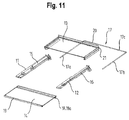
- the shelf 8 according to Fig. 2 corresponds to an assembly of individual parts of the shelf 8, as for example in an exploded view in the Fig. 11 are shown.
- the shelf 8 comprises a first separate support bar 11 and a second separate support bar 12, a reardegutlagerplatte 13 and a frontdegutlagerplatte 14, and a first support arm 15 and a second support arm 16.
- the shelf 8 also has a bracket 17 which holds the items the shelf 8 holds together.
- the first separate support bar 11 and the second separate support bar 12 are on the one hand designed to be releasably held in a position used in the storage space on the holders 10 of the inner container 2 and on the other hand formed, the reardegutlagerplatte 13 and the frontdegutlagerplatte 14 on the two support strips 11, 12 to store so adjustable against each other that the frontdegutlagerplatte 14 in a first position, as in Fig. 2 and Fig. 6 represented adjoins the reardegutlagerplatte 13 to form a continuous bearing surface on the same level and in a second position, as in Fig. 4 shown, at least partially or completely overlapped with the reardegutlagerplatte 13.
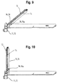
- the frontdegutlagerplatte 14 has a pivot bearing 18, in particular in the form of a torsion bar 18a through which the frontdegutlagerplatte 14 both pivotable, as well as displaceable between the two support strips 11, 12th guided, in particular stored.
- the pivot bearing 18 serves to the frontdegutlagerplatte 14, as in Fig. 3 shown to be able to raise at a front end edge 19, so that the plane of the frontdegutlagerplatte 14 is pivoted about the pivot bearing 18, as in the Fig. 7 is shown in detail to push the frontdegutlagerplatte 14 under the reardegutlagerplatte 13, as shown in the Fig. 8 is shown in more detail.
- Fig. 7 is shown in detail to push the frontdegutlagerplatte 14 under the reardegutlagerplatte 13
- Fig. 8 is shown in more detail.
- Fig. 11 As in Fig. 11 shown is the support strips 11, 12 connecting bracket 17 is formed, the separate support strips 11, 12, and the reardegutlagerplatte 13 and the frontdegutlagerplatte 14 comprehensive shelf 8 together.
- the bracket 17 is formed to hold the two support strips 11, 12 on the reardegutlagerplatte 13 and the frontdegutlagerplatte 14.
- the bracket 17 presses the two support strips 11, 12 from opposite sides against the reardegutlagerplatte 13 and the frontdegutlagerplatte 14 to press.
- the bracket 17 has a first leg 17a connected to the first support strip 11, a second leg 17b connected to the second support strip 12, and a middle web section 17c connecting the first leg 17a to the second leg 17b.
- the bracket 17 is formed in the illustrated embodiment of a U-shaped bent wire.
- the center web portion 17c of the bracket 17 forms a pivot bearing in the form of an axis 20 on which a hub sleeve 21 is rotatably mounted in the form of a circular cross-section, laterally provided with a longitudinal slot groove, such that the reardegutlagerplatte 13 about a horizontal axis can be folded.
- This pivot bearing is except in the Fig. 11 in exploded perspective view, also in Fig. 14 shown in cross section.
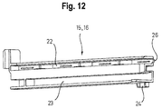
- the Fig. 12 shows an exemplary holding arm 15, 16.
- the holding arm 15, 16 has a groove-like clamping portion 22 in which a lateral edge portion of the reardegutlagerplatte 13 is mounted, in particular fixed.
- Below the clamping portion 22 extends in a parallel orientation a groove-like guides 23 in which the frontdegutlagerplatte 14 by means of the pivot bearing 18, in particular of the torsion bar 18a and its end portions is mounted and pulled out.
- Two opposite lever arms 15, 16 are, as in the Fig. 13 shown pivotally mounted on the two support strips 11, 12.
- the two lever arms 15, 16 are thereby formed to pivot the reardegutlagerplatte 13 together with the frontdegutlagerplatte 14.
- Each lever arm 15, 16 has a fixing projection 24 which engages positively in a recess 25 on the associated support bar 11, 12 in a position pivoted the reardegutlagerplatte 13 in a horizontal orientation of the respective support arm 15, 16, as in particular Fig. 13 is shown.
- Fig. 12 is also a projection 26 and in Fig. 14 a projection 26a is shown at a front end edge of the rear cooling goods storage plate 13.
- the projection 26a may extend in particular over the entire width of the front edge or the reardegutlagerplatte 13.
- the projection 26a fits into a corresponding groove 27 on the frontdegutlagerplatte 14 when the frontdegutlagerplatte 14 connects to the reardegutlagerplatte 13 to form a continuous bearing surface on the same level.
Landscapes
- Engineering & Computer Science (AREA)
- Chemical & Material Sciences (AREA)
- Combustion & Propulsion (AREA)
- Physics & Mathematics (AREA)
- Mechanical Engineering (AREA)
- Thermal Sciences (AREA)
- General Engineering & Computer Science (AREA)
- Devices That Are Associated With Refrigeration Equipment (AREA)
Priority Applications (1)
| Application Number | Priority Date | Filing Date | Title |
|---|---|---|---|
| PL13789574T PL2926069T3 (pl) | 2012-11-28 | 2013-11-14 | Domowe urządzenie chłodnicze z półką |
Applications Claiming Priority (2)
| Application Number | Priority Date | Filing Date | Title |
|---|---|---|---|
| DE102012221801.7A DE102012221801A1 (de) | 2012-11-28 | 2012-11-28 | Haushaltskältegerät mit einem Fachboden |
| PCT/EP2013/073786 WO2014082858A1 (de) | 2012-11-28 | 2013-11-14 | Haushaltskältegerät mit einem fachboden |
Publications (2)
| Publication Number | Publication Date |
|---|---|
| EP2926069A1 EP2926069A1 (de) | 2015-10-07 |
| EP2926069B1 true EP2926069B1 (de) | 2016-11-02 |
Family
ID=49578310
Family Applications (1)
| Application Number | Title | Priority Date | Filing Date |
|---|---|---|---|
| EP13789574.4A Active EP2926069B1 (de) | 2012-11-28 | 2013-11-14 | Haushaltskältegerät mit einem fachboden |
Country Status (4)
| Country | Link |
|---|---|
| EP (1) | EP2926069B1 (pl) |
| DE (1) | DE102012221801A1 (pl) |
| PL (1) | PL2926069T3 (pl) |
| WO (1) | WO2014082858A1 (pl) |
Cited By (9)
| Publication number | Priority date | Publication date | Assignee | Title |
|---|---|---|---|---|
| USD839321S1 (en) | 2015-03-17 | 2019-01-29 | Whirlpool Corporation | Refrigerator |
| US10371436B2 (en) | 2017-11-08 | 2019-08-06 | Whirlpool Corporation | Bin assembly |
| US10473383B2 (en) | 2017-09-08 | 2019-11-12 | Whirlpool Corporation | Refrigerator shelf translation system |
| US10551071B2 (en) | 2018-05-11 | 2020-02-04 | Whirlpool Corporation | Oven rack system with removable support elements |
| USD883348S1 (en) | 2015-10-09 | 2020-05-05 | Whirlpool Corporation | Refrigerator shelf |
| US10677514B2 (en) | 2017-08-01 | 2020-06-09 | Whirlpool Corporation | Door bin with dual material and system lock |
| US10690400B2 (en) | 2017-05-11 | 2020-06-23 | Whirlpool Corporation | Household appliance comprising shelf arrangement |
| US10704825B2 (en) | 2015-03-17 | 2020-07-07 | Whirlpool Corporation | U-shaped tuck shelf |
| US11073329B2 (en) | 2018-10-31 | 2021-07-27 | Whirlpool Corporation | Refrigerator shelving frame with snap-in sliding insert |
Families Citing this family (11)
| Publication number | Priority date | Publication date | Assignee | Title |
|---|---|---|---|---|
| KR102026464B1 (ko) * | 2015-02-17 | 2019-11-04 | 삼성전자주식회사 | 가변선반장치 및 이를 포함한 냉장고 |
| DE102015206869A1 (de) | 2015-04-16 | 2016-10-20 | BSH Hausgeräte GmbH | Fachboden zum Unterteilen eines Kühlgutlagerraumes eines Haushaltskühlgerätes sowie Haushaltskühlgerät |
| US10281197B2 (en) | 2016-10-11 | 2019-05-07 | Whirlpool Corporation | Quick shelf adjustment mechanism for a refrigerating appliance |
| DE102018118513A1 (de) * | 2018-06-27 | 2020-01-02 | Liebherr-Hausgeräte Ochsenhausen GmbH | Kühl- und/oder Gefriergerät |
| CN111380314B (zh) * | 2018-12-28 | 2022-01-25 | 海尔智家股份有限公司 | 搁物架组件及具有其的冰箱 |
| CN111380315B (zh) * | 2018-12-28 | 2022-01-21 | 海尔智家股份有限公司 | 搁物架组件及具有其的冰箱 |
| US10753674B1 (en) | 2019-02-20 | 2020-08-25 | Whirlpool Corporation | Refrigerator tuck shelf with flush profile and co-injected fixed glass |
| CN110631322B (zh) * | 2019-10-14 | 2024-06-18 | 创维电器股份有限公司 | 一种翻转玻璃层架组件及具有该组件的冰箱 |
| DE102020211569A1 (de) * | 2020-09-15 | 2022-03-17 | BSH Hausgeräte GmbH | Ablageplattenanordnung mit Trägerrahmen mit einer Profilschiene aus Metall, sowie Haushaltskältegerät |
| CN215809645U (zh) * | 2021-03-29 | 2022-02-11 | 博西华电器(江苏)有限公司 | 搁盘组件与制冷器具 |
| US20240337433A1 (en) * | 2021-07-26 | 2024-10-10 | Lg Electronics Inc. | Refrigerator |
Family Cites Families (5)
| Publication number | Priority date | Publication date | Assignee | Title |
|---|---|---|---|---|
| JP3019709B2 (ja) * | 1994-01-27 | 2000-03-13 | 三菱電機株式会社 | 冷凍冷蔵庫の伸縮棚装置 |
| JPH0835765A (ja) * | 1994-07-20 | 1996-02-06 | Fujitsu General Ltd | 電気冷蔵庫の載置棚 |
| DE202005016490U1 (de) * | 2005-07-21 | 2006-11-23 | Liebherr-Hausgeräte Ochsenhausen GmbH | Kühl- und/oder Gefriergerät |
| ITTO20080820A1 (it) * | 2008-11-06 | 2010-05-07 | Indesit Co Spa | Apparato di refrigerazione |
| DE102009046027A1 (de) | 2009-10-27 | 2011-05-05 | BSH Bosch und Siemens Hausgeräte GmbH | Kältegerät und Kühlgutträger mit unterteilter Abstellplatte |
-
2012
- 2012-11-28 DE DE102012221801.7A patent/DE102012221801A1/de not_active Withdrawn
-
2013
- 2013-11-14 PL PL13789574T patent/PL2926069T3/pl unknown
- 2013-11-14 WO PCT/EP2013/073786 patent/WO2014082858A1/de not_active Ceased
- 2013-11-14 EP EP13789574.4A patent/EP2926069B1/de active Active
Cited By (13)
| Publication number | Priority date | Publication date | Assignee | Title |
|---|---|---|---|---|
| USD839321S1 (en) | 2015-03-17 | 2019-01-29 | Whirlpool Corporation | Refrigerator |
| US11598577B2 (en) | 2015-03-17 | 2023-03-07 | Whirlpool Corporation | U-shaped tuck shelf |
| US10704825B2 (en) | 2015-03-17 | 2020-07-07 | Whirlpool Corporation | U-shaped tuck shelf |
| USD926235S1 (en) | 2015-10-09 | 2021-07-27 | Whirlpool Corporation | Refrigerator shelf |
| USD883348S1 (en) | 2015-10-09 | 2020-05-05 | Whirlpool Corporation | Refrigerator shelf |
| US10690400B2 (en) | 2017-05-11 | 2020-06-23 | Whirlpool Corporation | Household appliance comprising shelf arrangement |
| US11371771B2 (en) | 2017-05-11 | 2022-06-28 | Whirlpool Corporation | Household appliance comprising shelf arrangement |
| US12066244B2 (en) | 2017-05-11 | 2024-08-20 | Whirlpool Corporation | Household appliance comprising shelf arrangement |
| US10677514B2 (en) | 2017-08-01 | 2020-06-09 | Whirlpool Corporation | Door bin with dual material and system lock |
| US10473383B2 (en) | 2017-09-08 | 2019-11-12 | Whirlpool Corporation | Refrigerator shelf translation system |
| US10371436B2 (en) | 2017-11-08 | 2019-08-06 | Whirlpool Corporation | Bin assembly |
| US10551071B2 (en) | 2018-05-11 | 2020-02-04 | Whirlpool Corporation | Oven rack system with removable support elements |
| US11073329B2 (en) | 2018-10-31 | 2021-07-27 | Whirlpool Corporation | Refrigerator shelving frame with snap-in sliding insert |
Also Published As
| Publication number | Publication date |
|---|---|
| WO2014082858A1 (de) | 2014-06-05 |
| DE102012221801A1 (de) | 2014-05-28 |
| PL2926069T3 (pl) | 2017-05-31 |
| EP2926069A1 (de) | 2015-10-07 |
Similar Documents
| Publication | Publication Date | Title |
|---|---|---|
| EP2926069B1 (de) | Haushaltskältegerät mit einem fachboden | |
| EP2606300B1 (de) | Kältegerät mit ablagefläche zur ablage von kühlgut | |
| EP2913610B1 (de) | Haushaltskältegerät mit einem Fachboden und einer am Fachboden gelagerten Haltevorrichtung | |
| DE102011075102A1 (de) | Haushaltskältegerät mit einer Haltevorrichtung zur Lagerung eines Fachbodens | |
| EP2818813B1 (de) | Kältegerät mit einer Tragschiene für einen Fachboden | |
| EP2508826A2 (de) | Trenneinrichtung, Lagerbehälter und Haushaltsgerät | |
| WO2007144182A2 (de) | Kühl- und/oder gefriergerät | |
| DE3200357A1 (de) | Abschirmanordnung zur thermischen isolation einer zugriffsoeffnung einer kuehlvitrine | |
| EP2218994B1 (de) | Kältegerät mit ausziehbare Abstellplatten untergreifenden Auflagern | |
| DE102009028423A1 (de) | Haushaltskältegerät mit einer Linearführung für eine Auszugsplatte, insbesondere Glasplatte | |
| EP2606296B1 (de) | Kältegerät mit einer tragschiene für einen fachboden | |
| EP3136027B1 (de) | Haushaltskältegerät mit einer lagerfach-vorderwand | |
| EP3081885B1 (de) | Haushaltskühlgerät mit einem fachboden | |
| DE102012001374B4 (de) | Kühl- und/oder Gefriergerät | |
| EP2603750B1 (de) | Ein kühlgerät mit einem regaltrennelement | |
| EP2549211B1 (de) | Kältegerät mit schwenkbarem Kühlgutträger | |
| EP3457058B1 (de) | Kältegerät mit einem fachboden | |
| WO2010149537A2 (de) | Kältegerät, insbesondere haushaltskältegerät mit aufnahmen für halter von kühlgutablagen | |
| DE102014221696A1 (de) | Haushaltskältegerät mit einem in seinem Verwindungswinkel begrenzten Eisstückebereiter | |
| EP2508825A2 (de) | Kältegerät, insbesondere Haushaltskältegerät | |
| EP2561293B1 (de) | Türblatt und kältegerät mit einem türblatt | |
| DE102014221712A1 (de) | Haushaltskältegerät mit einem im Gefrierraum verriegelbar gelagerten mechanischen Eisstückebereiter | |
| DE102011080373A1 (de) | Haushaltskältegerät, aufweisend einen Türabsteller mit einem Gestalt veränderlichen Bodenabschnitt | |
| DE102014115658A1 (de) | Warenpräsentationsmöbel | |
| WO2016062562A1 (de) | Haushaltskältegerät mit punkt- und/oder linienberührend auflagernden tragmitteln |
Legal Events
| Date | Code | Title | Description |
|---|---|---|---|
| PUAI | Public reference made under article 153(3) epc to a published international application that has entered the european phase |
Free format text: ORIGINAL CODE: 0009012 |
|
| 17P | Request for examination filed |
Effective date: 20150629 |
|
| AK | Designated contracting states |
Kind code of ref document: A1 Designated state(s): AL AT BE BG CH CY CZ DE DK EE ES FI FR GB GR HR HU IE IS IT LI LT LU LV MC MK MT NL NO PL PT RO RS SE SI SK SM TR |
|
| AX | Request for extension of the european patent |
Extension state: BA ME |
|
| DAX | Request for extension of the european patent (deleted) | ||
| GRAP | Despatch of communication of intention to grant a patent |
Free format text: ORIGINAL CODE: EPIDOSNIGR1 |
|
| INTG | Intention to grant announced |
Effective date: 20160614 |
|
| GRAS | Grant fee paid |
Free format text: ORIGINAL CODE: EPIDOSNIGR3 |
|
| GRAA | (expected) grant |
Free format text: ORIGINAL CODE: 0009210 |
|
| AK | Designated contracting states |
Kind code of ref document: B1 Designated state(s): AL AT BE BG CH CY CZ DE DK EE ES FI FR GB GR HR HU IE IS IT LI LT LU LV MC MK MT NL NO PL PT RO RS SE SI SK SM TR |
|
| REG | Reference to a national code |
Ref country code: GB Ref legal event code: FG4D Free format text: NOT ENGLISH |
|
| REG | Reference to a national code |
Ref country code: AT Ref legal event code: REF Ref document number: 842273 Country of ref document: AT Kind code of ref document: T Effective date: 20161115 Ref country code: CH Ref legal event code: EP |
|
| REG | Reference to a national code |
Ref country code: IE Ref legal event code: FG4D Free format text: LANGUAGE OF EP DOCUMENT: GERMAN |
|
| REG | Reference to a national code |
Ref country code: DE Ref legal event code: R096 Ref document number: 502013005234 Country of ref document: DE |
|
| PG25 | Lapsed in a contracting state [announced via postgrant information from national office to epo] |
Ref country code: LV Free format text: LAPSE BECAUSE OF FAILURE TO SUBMIT A TRANSLATION OF THE DESCRIPTION OR TO PAY THE FEE WITHIN THE PRESCRIBED TIME-LIMIT Effective date: 20161102 |
|
| REG | Reference to a national code |
Ref country code: NL Ref legal event code: MP Effective date: 20161102 |
|
| REG | Reference to a national code |
Ref country code: LT Ref legal event code: MG4D |
|
| PG25 | Lapsed in a contracting state [announced via postgrant information from national office to epo] |
Ref country code: GR Free format text: LAPSE BECAUSE OF FAILURE TO SUBMIT A TRANSLATION OF THE DESCRIPTION OR TO PAY THE FEE WITHIN THE PRESCRIBED TIME-LIMIT Effective date: 20170203 Ref country code: SE Free format text: LAPSE BECAUSE OF FAILURE TO SUBMIT A TRANSLATION OF THE DESCRIPTION OR TO PAY THE FEE WITHIN THE PRESCRIBED TIME-LIMIT Effective date: 20161102 Ref country code: LT Free format text: LAPSE BECAUSE OF FAILURE TO SUBMIT A TRANSLATION OF THE DESCRIPTION OR TO PAY THE FEE WITHIN THE PRESCRIBED TIME-LIMIT Effective date: 20161102 Ref country code: NO Free format text: LAPSE BECAUSE OF FAILURE TO SUBMIT A TRANSLATION OF THE DESCRIPTION OR TO PAY THE FEE WITHIN THE PRESCRIBED TIME-LIMIT Effective date: 20170202 Ref country code: NL Free format text: LAPSE BECAUSE OF FAILURE TO SUBMIT A TRANSLATION OF THE DESCRIPTION OR TO PAY THE FEE WITHIN THE PRESCRIBED TIME-LIMIT Effective date: 20161102 |
|
| PG25 | Lapsed in a contracting state [announced via postgrant information from national office to epo] |
Ref country code: BE Free format text: LAPSE BECAUSE OF NON-PAYMENT OF DUE FEES Effective date: 20161130 Ref country code: RS Free format text: LAPSE BECAUSE OF FAILURE TO SUBMIT A TRANSLATION OF THE DESCRIPTION OR TO PAY THE FEE WITHIN THE PRESCRIBED TIME-LIMIT Effective date: 20161102 Ref country code: FI Free format text: LAPSE BECAUSE OF FAILURE TO SUBMIT A TRANSLATION OF THE DESCRIPTION OR TO PAY THE FEE WITHIN THE PRESCRIBED TIME-LIMIT Effective date: 20161102 Ref country code: ES Free format text: LAPSE BECAUSE OF FAILURE TO SUBMIT A TRANSLATION OF THE DESCRIPTION OR TO PAY THE FEE WITHIN THE PRESCRIBED TIME-LIMIT Effective date: 20161102 Ref country code: HR Free format text: LAPSE BECAUSE OF FAILURE TO SUBMIT A TRANSLATION OF THE DESCRIPTION OR TO PAY THE FEE WITHIN THE PRESCRIBED TIME-LIMIT Effective date: 20161102 Ref country code: IS Free format text: LAPSE BECAUSE OF FAILURE TO SUBMIT A TRANSLATION OF THE DESCRIPTION OR TO PAY THE FEE WITHIN THE PRESCRIBED TIME-LIMIT Effective date: 20170302 Ref country code: PT Free format text: LAPSE BECAUSE OF FAILURE TO SUBMIT A TRANSLATION OF THE DESCRIPTION OR TO PAY THE FEE WITHIN THE PRESCRIBED TIME-LIMIT Effective date: 20170302 |
|
| REG | Reference to a national code |
Ref country code: CH Ref legal event code: PL |
|
| PG25 | Lapsed in a contracting state [announced via postgrant information from national office to epo] |
Ref country code: EE Free format text: LAPSE BECAUSE OF FAILURE TO SUBMIT A TRANSLATION OF THE DESCRIPTION OR TO PAY THE FEE WITHIN THE PRESCRIBED TIME-LIMIT Effective date: 20161102 Ref country code: CZ Free format text: LAPSE BECAUSE OF FAILURE TO SUBMIT A TRANSLATION OF THE DESCRIPTION OR TO PAY THE FEE WITHIN THE PRESCRIBED TIME-LIMIT Effective date: 20161102 Ref country code: CH Free format text: LAPSE BECAUSE OF NON-PAYMENT OF DUE FEES Effective date: 20161130 Ref country code: RO Free format text: LAPSE BECAUSE OF FAILURE TO SUBMIT A TRANSLATION OF THE DESCRIPTION OR TO PAY THE FEE WITHIN THE PRESCRIBED TIME-LIMIT Effective date: 20161102 Ref country code: LI Free format text: LAPSE BECAUSE OF NON-PAYMENT OF DUE FEES Effective date: 20161130 Ref country code: SK Free format text: LAPSE BECAUSE OF FAILURE TO SUBMIT A TRANSLATION OF THE DESCRIPTION OR TO PAY THE FEE WITHIN THE PRESCRIBED TIME-LIMIT Effective date: 20161102 Ref country code: DK Free format text: LAPSE BECAUSE OF FAILURE TO SUBMIT A TRANSLATION OF THE DESCRIPTION OR TO PAY THE FEE WITHIN THE PRESCRIBED TIME-LIMIT Effective date: 20161102 |
|
| REG | Reference to a national code |
Ref country code: DE Ref legal event code: R097 Ref document number: 502013005234 Country of ref document: DE |
|
| REG | Reference to a national code |
Ref country code: IE Ref legal event code: MM4A |
|
| PG25 | Lapsed in a contracting state [announced via postgrant information from national office to epo] |
Ref country code: BG Free format text: LAPSE BECAUSE OF FAILURE TO SUBMIT A TRANSLATION OF THE DESCRIPTION OR TO PAY THE FEE WITHIN THE PRESCRIBED TIME-LIMIT Effective date: 20170202 Ref country code: SM Free format text: LAPSE BECAUSE OF FAILURE TO SUBMIT A TRANSLATION OF THE DESCRIPTION OR TO PAY THE FEE WITHIN THE PRESCRIBED TIME-LIMIT Effective date: 20161102 |
|
| PLBE | No opposition filed within time limit |
Free format text: ORIGINAL CODE: 0009261 |
|
| STAA | Information on the status of an ep patent application or granted ep patent |
Free format text: STATUS: NO OPPOSITION FILED WITHIN TIME LIMIT |
|
| PG25 | Lapsed in a contracting state [announced via postgrant information from national office to epo] |
Ref country code: LU Free format text: LAPSE BECAUSE OF NON-PAYMENT OF DUE FEES Effective date: 20161130 Ref country code: MC Free format text: LAPSE BECAUSE OF FAILURE TO SUBMIT A TRANSLATION OF THE DESCRIPTION OR TO PAY THE FEE WITHIN THE PRESCRIBED TIME-LIMIT Effective date: 20161102 |
|
| REG | Reference to a national code |
Ref country code: FR Ref legal event code: ST Effective date: 20170904 |
|
| 26N | No opposition filed |
Effective date: 20170803 |
|
| PG25 | Lapsed in a contracting state [announced via postgrant information from national office to epo] |
Ref country code: FR Free format text: LAPSE BECAUSE OF NON-PAYMENT OF DUE FEES Effective date: 20170102 |
|
| PG25 | Lapsed in a contracting state [announced via postgrant information from national office to epo] |
Ref country code: IE Free format text: LAPSE BECAUSE OF NON-PAYMENT OF DUE FEES Effective date: 20161114 Ref country code: SI Free format text: LAPSE BECAUSE OF FAILURE TO SUBMIT A TRANSLATION OF THE DESCRIPTION OR TO PAY THE FEE WITHIN THE PRESCRIBED TIME-LIMIT Effective date: 20161102 |
|
| REG | Reference to a national code |
Ref country code: BE Ref legal event code: MM Effective date: 20161130 |
|
| PG25 | Lapsed in a contracting state [announced via postgrant information from national office to epo] |
Ref country code: HU Free format text: LAPSE BECAUSE OF FAILURE TO SUBMIT A TRANSLATION OF THE DESCRIPTION OR TO PAY THE FEE WITHIN THE PRESCRIBED TIME-LIMIT; INVALID AB INITIO Effective date: 20131114 |
|
| PG25 | Lapsed in a contracting state [announced via postgrant information from national office to epo] |
Ref country code: MK Free format text: LAPSE BECAUSE OF FAILURE TO SUBMIT A TRANSLATION OF THE DESCRIPTION OR TO PAY THE FEE WITHIN THE PRESCRIBED TIME-LIMIT Effective date: 20161102 Ref country code: CY Free format text: LAPSE BECAUSE OF FAILURE TO SUBMIT A TRANSLATION OF THE DESCRIPTION OR TO PAY THE FEE WITHIN THE PRESCRIBED TIME-LIMIT Effective date: 20161102 |
|
| GBPC | Gb: european patent ceased through non-payment of renewal fee |
Effective date: 20171114 |
|
| PG25 | Lapsed in a contracting state [announced via postgrant information from national office to epo] |
Ref country code: MT Free format text: LAPSE BECAUSE OF FAILURE TO SUBMIT A TRANSLATION OF THE DESCRIPTION OR TO PAY THE FEE WITHIN THE PRESCRIBED TIME-LIMIT Effective date: 20161102 |
|
| PG25 | Lapsed in a contracting state [announced via postgrant information from national office to epo] |
Ref country code: GB Free format text: LAPSE BECAUSE OF NON-PAYMENT OF DUE FEES Effective date: 20171114 |
|
| REG | Reference to a national code |
Ref country code: AT Ref legal event code: MM01 Ref document number: 842273 Country of ref document: AT Kind code of ref document: T Effective date: 20181114 |
|
| PG25 | Lapsed in a contracting state [announced via postgrant information from national office to epo] |
Ref country code: AT Free format text: LAPSE BECAUSE OF NON-PAYMENT OF DUE FEES Effective date: 20181114 |
|
| PG25 | Lapsed in a contracting state [announced via postgrant information from national office to epo] |
Ref country code: AL Free format text: LAPSE BECAUSE OF FAILURE TO SUBMIT A TRANSLATION OF THE DESCRIPTION OR TO PAY THE FEE WITHIN THE PRESCRIBED TIME-LIMIT Effective date: 20161102 |
|
| PGFP | Annual fee paid to national office [announced via postgrant information from national office to epo] |
Ref country code: IT Payment date: 20221130 Year of fee payment: 10 |
|
| PG25 | Lapsed in a contracting state [announced via postgrant information from national office to epo] |
Ref country code: IT Free format text: LAPSE BECAUSE OF NON-PAYMENT OF DUE FEES Effective date: 20231114 |
|
| PG25 | Lapsed in a contracting state [announced via postgrant information from national office to epo] |
Ref country code: IT Free format text: LAPSE BECAUSE OF NON-PAYMENT OF DUE FEES Effective date: 20231114 |
|
| PGFP | Annual fee paid to national office [announced via postgrant information from national office to epo] |
Ref country code: DE Payment date: 20241130 Year of fee payment: 12 |
|
| PGFP | Annual fee paid to national office [announced via postgrant information from national office to epo] |
Ref country code: PL Payment date: 20241105 Year of fee payment: 12 |
|
| PGFP | Annual fee paid to national office [announced via postgrant information from national office to epo] |
Ref country code: TR Payment date: 20241105 Year of fee payment: 12 |