EP2926069B1 - Domestic refrigeration device having a compartment bottom - Google Patents
Domestic refrigeration device having a compartment bottom Download PDFInfo
- Publication number
- EP2926069B1 EP2926069B1 EP13789574.4A EP13789574A EP2926069B1 EP 2926069 B1 EP2926069 B1 EP 2926069B1 EP 13789574 A EP13789574 A EP 13789574A EP 2926069 B1 EP2926069 B1 EP 2926069B1
- Authority
- EP
- European Patent Office
- Prior art keywords
- goods
- cooled
- storage plate
- kühlgutlagerplatte
- refrigeration device
- Prior art date
- Legal status (The legal status is an assumption and is not a legal conclusion. Google has not performed a legal analysis and makes no representation as to the accuracy of the status listed.)
- Active
Links
- 238000005057 refrigeration Methods 0.000 title claims description 19
- 230000000717 retained effect Effects 0.000 claims 2
- 239000011521 glass Substances 0.000 description 9
- 238000001816 cooling Methods 0.000 description 8
- 239000002131 composite material Substances 0.000 description 4
- 238000003825 pressing Methods 0.000 description 2
- 229910000831 Steel Inorganic materials 0.000 description 1
- 230000015572 biosynthetic process Effects 0.000 description 1
- 238000004140 cleaning Methods 0.000 description 1
- 235000013399 edible fruits Nutrition 0.000 description 1
- 238000007710 freezing Methods 0.000 description 1
- 230000008014 freezing Effects 0.000 description 1
- 235000013611 frozen food Nutrition 0.000 description 1
- 239000007787 solid Substances 0.000 description 1
- 239000010959 steel Substances 0.000 description 1
- 235000013311 vegetables Nutrition 0.000 description 1
Images


Classifications
-
- F—MECHANICAL ENGINEERING; LIGHTING; HEATING; WEAPONS; BLASTING
- F25—REFRIGERATION OR COOLING; COMBINED HEATING AND REFRIGERATION SYSTEMS; HEAT PUMP SYSTEMS; MANUFACTURE OR STORAGE OF ICE; LIQUEFACTION SOLIDIFICATION OF GASES
- F25D—REFRIGERATORS; COLD ROOMS; ICE-BOXES; COOLING OR FREEZING APPARATUS NOT OTHERWISE PROVIDED FOR
- F25D25/00—Charging, supporting, and discharging the articles to be cooled
- F25D25/02—Charging, supporting, and discharging the articles to be cooled by shelves
-
- F—MECHANICAL ENGINEERING; LIGHTING; HEATING; WEAPONS; BLASTING
- F25—REFRIGERATION OR COOLING; COMBINED HEATING AND REFRIGERATION SYSTEMS; HEAT PUMP SYSTEMS; MANUFACTURE OR STORAGE OF ICE; LIQUEFACTION SOLIDIFICATION OF GASES
- F25D—REFRIGERATORS; COLD ROOMS; ICE-BOXES; COOLING OR FREEZING APPARATUS NOT OTHERWISE PROVIDED FOR
- F25D2325/00—Charging, supporting or discharging the articles to be cooled, not provided for in other groups of this subclass
- F25D2325/021—Shelves with several possible configurations
Definitions
- the invention relates to a household refrigeration appliance, comprising a heat-insulating inner container, which is designed to limit at least one storage space for refrigerated goods, a in the inner container at opposite, detachable from the inner container support bars shelf comprising a rear support plate and a front support plate which is formed to connect in a first position to the rear support plate to form a continuous shelf on the same level and to overlap in a second position with the rear support plate at least partially or completely.
- Refrigeration appliances are known in which a front partial plate of a two-part storage tray can be removed separately from a rear partial plate or displaced into a position overlapping with the rear partial plate, in order to combine two compartments normally separated by the storage tray in a front region of a storage chamber of the refrigeration appliance and so to make room for the storage of refrigerated goods, which is higher than each of the two subjects.
- a front partial plate of a two-part storage tray can be removed separately from a rear partial plate or displaced into a position overlapping with the rear partial plate, in order to combine two compartments normally separated by the storage tray in a front region of a storage chamber of the refrigeration appliance and so to make room for the storage of refrigerated goods, which is higher than each of the two subjects.
- In order to eliminate the subdivision also in a rear region of the interior it is necessary in such a conventional refrigeration device to remove the rear sub-plate. This is especially troublesome when a front area of the storage chamber is already occupied by combinigem refrigerated goods, which
- the DE 10 2009 046 027 A1 therefore, describes a refrigeration device, in particular household refrigeration appliance, with a storage plate, which is divided into at least one rear part plate and a displaced between an exploded and an overlapping with the rear part plate position front partial plate, wherein the partial plates from the overlapping position out about a horizontal axis are pivotable.
- the object of the invention is to provide a mounted in the inner container on opposite support rails shelf, which includes a rear support plate and a front support plate, in which the complete shelf with the support bars and the two support plates can be offset in height in the inner container in a simple manner.
- a household refrigerating appliance comprising a heat-insulating inner container, which is designed to limit at least one storage space for items to be refrigerated, and which has two opposite side walls, which are provided with holders, further comprising a shelf which is a first separate Support bar and a second separate support bar comprises, on the one hand are formed to be releasably held in a position used in the storage space on the holders of the inner container and on the other hand are designed to store a reardegutlagerplatte and a frontdegutlagerplatte to the two support bars against each adjustable in that the frontdegutlagerplatte connects in a first position to the reardegutlagerplatte to form a continuous bearing surface on the same level and in a second position with the reardegutlagerplatte at least partially or fully constantly overlapping, further comprising a bracket connecting the support bracket, which is designed to hold together the separate support strips, and the reardegutlagerplatte and the frontdegutlagerplatte comprehensive shelf.
- the bracket is formed by a U-shaped bent wire.
- the wire can be made of a rigid, in particular spring-elastic steel.
- the wire can basically have any desired cross-sectional shape.
- the bracket in particular the middle web portion has in all embodiments to form a pivot bearing on which the reardegutlagerplatte is mounted hinged about a horizontal axis, but in particular a circular cross-section.
- the reardegutlagerplatte be pivotally mounted on the middle web section.
- the holders can be formed, for example, by side wall sections attracted to the inner container, which can be designed either as projections or as recesses. Accordingly, the holders can be formed, as is the case with groove-like recesses or strip-like projections known to those skilled in the art of common refrigeration appliances.
- the holders may at least substantially or completely over the entire depth of the inner container in horizontal planes, if necessary several times spaced above each other extend.
- the support strips may be designed like a rail and be adapted in size and shape to the holder so that the support strips with one of these encompassed holding portion can connect in particular form-fitting manner with the holders.
- the holding portions of the support bars are simply on simsartigen projections of the holder or the holding portions of the support strips fit positively locking, if necessary, in a groove-like recesses of the holder.
- the reardegutlagerplatte On the support rails guides may be provided on which on the one hand, the reardegutlagerplatte is pivotally mounted and on the other hand, the frontdegutlagerplatte under or over the reardegutlagerplatte slidably, pivotally and / or hinged.
- the shelf can form an assembly of reardegutlagerplatte, frontdegutlagerplatte and the two opposite, the twoegutlagerplatte enclosing support strips.
- the bracket can be designed to hold two opposite support strips at such a distance from each other together, in which the reardegutlagerplatte and the frontdegutlagerplatte are stored in particular captive even when removed from the inner container shelf between the support bars.
- the bracket is thus designed to hold the two separate support strips with the reardegutlagerplatte and the frontdegutlagerplatte in a composite obtained the function of the twodegutlagerplatte.
- the shelf can be removed as a unit from a stored in the inner container altitude, possibly used at a different altitude again in the inner container without the shelf are broken down into its parts of left support bar, right support bar, reardegutlagerplatte and frontdegutlagerplatte got to. Also can be dispensed with a permanently solid composite, as is the case for example with a firmly overmolded glass plate.
- the shelf can on the one hand taken as a composite in a simple manner or offset in height, but the shelf can on the other hand, for example, for cleaning purposes broken down into its parts of left support bar, right support bar, reardegutlagerplatte and frontdegutlagerplatte, in particular be dismantled by the inventive bracket is removed.
- the bracket can be releasably connected to the two support strips.
- the bracket can be designed to hold the two support strips on the reardegutlagerplatte and / or on the frontdegutlagerplatte.
- the two support strips may have correspondingly shaped guides, in particular grooves.
- the bracket can thus be designed to hold the two support strips in a form-fitting manner with the reardegutlagerplatte and / or on the frontdegutlagerplatte engaged, so that thedegutlagerplatten can not fall off the support strips, even if the composite of the shelf from the inner container is taken.
- the bracket may be formed to press the two support strips from opposite sides against the reardegutlagerplatte and the frontdegutlagerplatte.
- the bracket can therefore be designed as a spring clip, which presses the two support strips against the opposite side edges of the reardegutlagerplatte and frontdegutlagerplatte.
- the support bars can also press against separate additional strips or molded edge borders, which are firmly connected to the reardegutlagerplatte and / or frontdegutlagerplatte.
- the bracket may have a first leg connected to the one support strip, a second leg connected to the other support strip, and a middle web section connecting the first leg to the second leg.
- the center land portion is formed to hold the first leg and the second leg at a fixed distance from each other.
- the two legs can in particular be aligned parallel to one another, are at a fixed distance from one another and extend away from the middle web section at a particularly right angle to the longitudinal extent of the center web section.
- a first support arm may be pivotally mounted on the one support bar, in particular be pivotally mounted on the bracket or the middle web portion of the bracket, on which a lateral edge portion of the reardegutlagerplatte mounted, in particular secured and on the other support bar, a second Retaining arm be pivotally mounted, in particular be pivotally mounted on the bracket or the middle web portion of the bracket, on which an opposite lateral edge portion of the reardegutlagerplatte stored, in particular fixed.
- the two pivotally mounted support arm so far carry the reardegutlagerplatte and store these pivotally with respect to the two support strips. In other words, the reardegutlagerplatte can be folded by pivoting the two support arms from a horizontal position to a vertical position.
- the first support arm and / or the second support arm may be configured to pivot the reardegutlagerplatte together with the frontdegutlagerplatte.
- the first support arm and / or the second support arm may have guides in which the overlapping with the reardegutlagerplatte frontdegutlagerplatte held, in particular slidably guided.
- the first holding arm and the second holding arm may each have a fixing projection, which engages positively in a recess of the associated support bar in a position of the respective holding arm which is pivoted in a horizontal orientation relative to the rear cooling goods storage plate.
- the frontdegutlagerplatte have a pivot bearing, in particular in the form of a torsion bar through which the frontdegutlagerplatte both pivotally guided and slidably between the two support bars, in particular is stored.
- the frontdegutlagerplatte may have one or more bearing eyes, which are rotatably mounted on the torsion bar, or rigidly connected to the torsion bar, in which case the opposite, facing away from each other end portions of the torsion bar can be rotatably mounted in abutment on the support bars.
- the opposite, pointing away from each other end portions of the torsion bar can then be slidably mounted in guides or grooves of the support strips.
- the bracket may have a first leg connected to the one support bar and a second leg connected to the other support bar, wherein the two legs or at least a respective portion of the two legs are aligned in an angle different from the parallel orientation to each other in one stored in the inner container position of the shelf to push the support strips with spring force against the holder of the inner container.
- the support strips are pressed against the holder, in particular in grooves of the inner container by spring force, so that inadvertent release of the support bars prevented by the holders or at least the risk of unintentional release is reduced.
- a front end edge of the reardegutlagerplatte a projection, in particular over the entire width of the front edge extending projection edge have, in the first position in which the frontdegutlagerplatte to the reardegutlagerplatte to form a continuous storage area on the same Plain connects, in a corresponding groove of the frontdegutlagerplatte inserts.
- an improved operability for the customer when stowing an unuseddegutlagerplatte, in particular glass plate in the interior of the cooling area can be achieved if necessary, without having to remove thisdegutlagerplatte, especially glass plate from the refrigerator.
- the shelf described above can also be referred to as a garage plate.
- This may be a garage plate and additionally a folding function.
- the rear half of the garage plate can be folded away, for example, together with the front half of the garage plate.
- a wire bow in U-shape can fulfill several functions.
- plastic parts On the outer leg of this U-bracket plastic parts can be latched, which may be provided for storage in the inner container. These plastic parts thus serve as bearing parts on the ribbed field, i. on the holders of the inner container.
- Another function of the U-bracket can be an outward pressing of the bearing parts, i. the support bars in order to ensure optimum storage of the support strips on the rib field, i. to ensure the holders. This can be achieved by overbending the wire legs.
- the corner angle is about 95 °, the leg is bent outwards.
- An additional function is the rotation axis for thedegutlagerplatte, in particular the glass plates.
- the rear half glass plate can be locked on the U-bracket.
- the wire diameter serves as a rotation axis.
- the rear halfdegutlagerplatte, in particular glass plate may be additionally provided in the horizontal position by a locking lug, which engage in the side panels. Thedegutlagerplatte, in particular glass plate is thus secured against falling out.
- the front halfdegutlagerplatte, in particular glass plate pushed under the rear halfdegutlagerplatte, in particular glass plate and the entire system can be turned up with each other on the wire hanger.
- An in Fig. 1 household refrigerating appliance 1 shown by way of example has a body 2 with an inner container 3.
- the inner container 3 is divided in the illustrated embodiment in an upper cooling compartment 4 and a freezer compartment 5 arranged below.
- the cooling space 4 is generally used for frost-free cooling of refrigerated goods, preferably at temperatures between plus 4 and plus 8 degrees Celsius. However, the cooling space 4 can also be designed as a zero-degree compartment, in particular for keeping fruit or vegetables fresh.
- the refrigerator 4 is accessible when the refrigerator door 6 is open.
- the freezer compartment 5 is generally used for freezing frozen food at about minus 18 degrees Celsius.
- the freezer compartment 5 is accessible when the freezer compartment door 7 is open. In the refrigerator 4 a plurality of shelves 8 are stored.
- a plurality of holders 10 may be provided on side walls 9 of the inner container 3 on opposite sides.
- the holders 10 may be formed, for example, by side wall sections attracted to the inner container 3, which may be designed either as projections or as recesses.
- the holders 10 may be formed by groove-like recesses or strip-like projections.
- the holders 10 may be at least substantially or completely extend over the entire depth of the inner container 3 in horizontal planes, if necessary several times spaced one above the other.
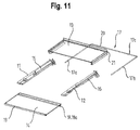
- FIG. 2 an exemplary embodiment of a shelf 8 according to the invention is shown.
- the shelf 8 according to Fig. 2 corresponds to an assembly of individual parts of the shelf 8, as for example in an exploded view in the Fig. 11 are shown.
- the shelf 8 comprises a first separate support bar 11 and a second separate support bar 12, a reardegutlagerplatte 13 and a frontdegutlagerplatte 14, and a first support arm 15 and a second support arm 16.
- the shelf 8 also has a bracket 17 which holds the items the shelf 8 holds together.
- the first separate support bar 11 and the second separate support bar 12 are on the one hand designed to be releasably held in a position used in the storage space on the holders 10 of the inner container 2 and on the other hand formed, the reardegutlagerplatte 13 and the frontdegutlagerplatte 14 on the two support strips 11, 12 to store so adjustable against each other that the frontdegutlagerplatte 14 in a first position, as in Fig. 2 and Fig. 6 represented adjoins the reardegutlagerplatte 13 to form a continuous bearing surface on the same level and in a second position, as in Fig. 4 shown, at least partially or completely overlapped with the reardegutlagerplatte 13.
- the frontdegutlagerplatte 14 has a pivot bearing 18, in particular in the form of a torsion bar 18a through which the frontdegutlagerplatte 14 both pivotable, as well as displaceable between the two support strips 11, 12th guided, in particular stored.
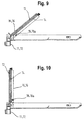
- the pivot bearing 18 serves to the frontdegutlagerplatte 14, as in Fig. 3 shown to be able to raise at a front end edge 19, so that the plane of the frontdegutlagerplatte 14 is pivoted about the pivot bearing 18, as in the Fig. 7 is shown in detail to push the frontdegutlagerplatte 14 under the reardegutlagerplatte 13, as shown in the Fig. 8 is shown in more detail.
- Fig. 7 is shown in detail to push the frontdegutlagerplatte 14 under the reardegutlagerplatte 13
- Fig. 8 is shown in more detail.
- Fig. 11 As in Fig. 11 shown is the support strips 11, 12 connecting bracket 17 is formed, the separate support strips 11, 12, and the reardegutlagerplatte 13 and the frontdegutlagerplatte 14 comprehensive shelf 8 together.
- the bracket 17 is formed to hold the two support strips 11, 12 on the reardegutlagerplatte 13 and the frontdegutlagerplatte 14.
- the bracket 17 presses the two support strips 11, 12 from opposite sides against the reardegutlagerplatte 13 and the frontdegutlagerplatte 14 to press.
- the bracket 17 has a first leg 17a connected to the first support strip 11, a second leg 17b connected to the second support strip 12, and a middle web section 17c connecting the first leg 17a to the second leg 17b.
- the bracket 17 is formed in the illustrated embodiment of a U-shaped bent wire.
- the center web portion 17c of the bracket 17 forms a pivot bearing in the form of an axis 20 on which a hub sleeve 21 is rotatably mounted in the form of a circular cross-section, laterally provided with a longitudinal slot groove, such that the reardegutlagerplatte 13 about a horizontal axis can be folded.
- This pivot bearing is except in the Fig. 11 in exploded perspective view, also in Fig. 14 shown in cross section.
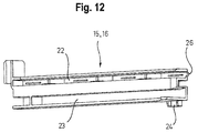
- the Fig. 12 shows an exemplary holding arm 15, 16.
- the holding arm 15, 16 has a groove-like clamping portion 22 in which a lateral edge portion of the reardegutlagerplatte 13 is mounted, in particular fixed.
- Below the clamping portion 22 extends in a parallel orientation a groove-like guides 23 in which the frontdegutlagerplatte 14 by means of the pivot bearing 18, in particular of the torsion bar 18a and its end portions is mounted and pulled out.
- Two opposite lever arms 15, 16 are, as in the Fig. 13 shown pivotally mounted on the two support strips 11, 12.
- the two lever arms 15, 16 are thereby formed to pivot the reardegutlagerplatte 13 together with the frontdegutlagerplatte 14.
- Each lever arm 15, 16 has a fixing projection 24 which engages positively in a recess 25 on the associated support bar 11, 12 in a position pivoted the reardegutlagerplatte 13 in a horizontal orientation of the respective support arm 15, 16, as in particular Fig. 13 is shown.
- Fig. 12 is also a projection 26 and in Fig. 14 a projection 26a is shown at a front end edge of the rear cooling goods storage plate 13.
- the projection 26a may extend in particular over the entire width of the front edge or the reardegutlagerplatte 13.
- the projection 26a fits into a corresponding groove 27 on the frontdegutlagerplatte 14 when the frontdegutlagerplatte 14 connects to the reardegutlagerplatte 13 to form a continuous bearing surface on the same level.
Description
Die Erfindung betrifft ein Haushaltskältegerät, aufweisend einen wärmeisolierenden Innenbehälter, der ausgebildet ist, wenigstens einen Lagerraum für Kältegut zu begrenzen, einen im Innenbehälter an gegenüberliegenden, von dem Innenbehälter lösbaren Tragleisten gelagerten Fachboden, der eine hintere Tragplatte und eine vordere Tragplatte umfasst, die ausgebildet ist, in einer ersten Stellung sich an die hintere Tragplatte zur Bildung einer durchgehenden Abstellfläche auf gleicher Ebene anzuschließen und in einer zweiten Stellung mit der hinteren Tragplatte zumindest teilweise oder vollständig zu überlappen.The invention relates to a household refrigeration appliance, comprising a heat-insulating inner container, which is designed to limit at least one storage space for refrigerated goods, a in the inner container at opposite, detachable from the inner container support bars shelf comprising a rear support plate and a front support plate which is formed to connect in a first position to the rear support plate to form a continuous shelf on the same level and to overlap in a second position with the rear support plate at least partially or completely.
Es sind Kältegeräte bekannt, bei denen eine vordere Teilplatte einer zweigeteilten Abstellplatte getrennt von einer hinteren Teilplatte entnehmbar oder in eine mit der hinteren Teilplatte überlappende Stellung verschiebbar ist, um in einem vorderen Bereich einer Lagerkammer des Kältegeräts zwei normalerweise durch die Abstellplatte voneinander getrennte Fächer zu vereinigen und so Platz für die Unterbringung von Kühlgut zu schaffen, das höher ist als jedes einzelne der beiden Fächer. Um die Unterteilung auch in einem hinteren Bereich des Innenraums zu beseitigen, ist es bei einem solchen herkömmlichen Kältegerät notwendig, die hintere Teilplatte auszubauen. Dies ist vor allem dann lästig, wenn ein vorderer Bereich der Lagerkammer bereits mit hochformatigem Kühlgut belegt ist, das ausgeräumt werden muss, bevor die hintere Teilplatte entfernt werden kann.Refrigeration appliances are known in which a front partial plate of a two-part storage tray can be removed separately from a rear partial plate or displaced into a position overlapping with the rear partial plate, in order to combine two compartments normally separated by the storage tray in a front region of a storage chamber of the refrigeration appliance and so to make room for the storage of refrigerated goods, which is higher than each of the two subjects. In order to eliminate the subdivision also in a rear region of the interior, it is necessary in such a conventional refrigeration device to remove the rear sub-plate. This is especially troublesome when a front area of the storage chamber is already occupied by hochformatigem refrigerated goods, which must be cleared before the rear part of the plate can be removed.
Die
Aus der
Die Aufgabe der Erfindung ist es, ein im Innenbehälter an gegenüberliegenden Tragleisten gelagerten Fachboden, der eine hintere Tragplatte und eine vordere Tragplatte umfasst anzugeben, bei dem der komplette Fachboden mit den Tragleisten und den beiden Tragplatten auf einfache Weise im Innenbehälter höhenversetzt werden kann.The object of the invention is to provide a mounted in the inner container on opposite support rails shelf, which includes a rear support plate and a front support plate, in which the complete shelf with the support bars and the two support plates can be offset in height in the inner container in a simple manner.
Die Aufgabe der Erfindung wird gelöst durch ein Haushaltskältegerät, aufweisend einen wärmeisolierenden Innenbehälter, der ausgebildet ist, wenigstens einen Lagerraum für Kältegut zu begrenzen, und der zwei gegenüberliegende Seitenwände aufweist, die mit Haltern versehen sind, des Weiteren aufweisend einen Fachboden, der eine erste separate Tragleiste und eine zweite separate Tragleiste umfasst, die einerseits ausgebildet sind, in einer in den Lagerraum eingesetzten Position an den Haltern des Innenbehälters lösbar gehalten zu werden und andererseits ausgebildet sind, eine hintere Kühlgutlagerplatte und eine vordere Kühlgutlagerplatte an den beiden Tragleisten derart gegeneinander verstellbar zu lagern, dass die vordere Kühlgutlagerplatte in einer ersten Stellung sich an die hintere Kühlgutlagerplatte zur Bildung einer durchgehenden Lagerfläche auf gleicher Ebene anschließt und in einer zweiten Stellung mit der hinteren Kühlgutlagerplatte zumindest teilweise oder vollständig überlappt, des Weiteren aufweisend einen die Tragleisten verbindenden Bügel, der ausgebildet ist, den die separaten Tragleisten, sowie die hintere Kühlgutlagerplatte und die vordere Kühlgutlagerplatte umfassenden Fachboden zusammenzuhalten.The object of the invention is achieved by a household refrigerating appliance, comprising a heat-insulating inner container, which is designed to limit at least one storage space for items to be refrigerated, and which has two opposite side walls, which are provided with holders, further comprising a shelf which is a first separate Support bar and a second separate support bar comprises, on the one hand are formed to be releasably held in a position used in the storage space on the holders of the inner container and on the other hand are designed to store a rear Kühlgutlagerplatte and a front Kühlgutlagerplatte to the two support bars against each adjustable in that the front Kühlgutlagerplatte connects in a first position to the rear Kühlgutlagerplatte to form a continuous bearing surface on the same level and in a second position with the rear Kühlgutlagerplatte at least partially or fully constantly overlapping, further comprising a bracket connecting the support bracket, which is designed to hold together the separate support strips, and the rear Kühlgutlagerplatte and the front Kühlgutlagerplatte comprehensive shelf.
Generell ist der Bügel von einem U-förmig gebogenen Draht gebildet. Der Draht kann aus einem biegesteifen, insbesondere federelastischen Stahl gefertigt sein. Der Draht kann grundsätzlich jede beliebige Querschnittsform aufweisen.Generally, the bracket is formed by a U-shaped bent wire. The wire can be made of a rigid, in particular spring-elastic steel. The wire can basically have any desired cross-sectional shape.
Der Bügel, insbesondere der Mittenstegabschnitt weist in allen Ausführungen zur Bildung eines Schwenklagers, an dem die hintere Kühlgutlagerplatte um eine horizontale Achse klappbar gelagert ist, jedoch insbesondere einen kreisförmigen Querschnitt auf. Aufgrund des kreisförmigen Querschnitts des Mittenstegabschnitts des Bügels kann beispielsweise die hinteren Kühlgutlagerplatte schwenkbar auf dem Mittenstegabschnitt gelagert sein. Die Halter können beispielsweise von am Innenbehälter angezogenen Seitenwandabschnitten gebildet werden, die entweder als Vorsprünge oder als Rücksprünge ausgeführt sein können. Die Halter können demgemäß, wie bei dem Fachmann von gängigen Kältegeräte bekannten nutenartigen Rücksprüngen oder leistenartigen Vorsprüngen gebildet werden. Die Halter können sich zumindest im Wesentlichen oder vollständig über die gesamte Tiefe des Innenbehälters in horizontalen Ebenen ggf. mehrfach beabstandet übereinander liegend erstrecken.The bracket, in particular the middle web portion has in all embodiments to form a pivot bearing on which the rear Kühlgutlagerplatte is mounted hinged about a horizontal axis, but in particular a circular cross-section. by virtue of of the circular cross-section of the middle web portion of the bracket, for example, the rear Kühlgutlagerplatte be pivotally mounted on the middle web section. The holders can be formed, for example, by side wall sections attracted to the inner container, which can be designed either as projections or as recesses. Accordingly, the holders can be formed, as is the case with groove-like recesses or strip-like projections known to those skilled in the art of common refrigeration appliances. The holders may at least substantially or completely over the entire depth of the inner container in horizontal planes, if necessary several times spaced above each other extend.
Die Tragleisten können schienenartig ausgeführt sein und in Größe und Gestalt an die Halter derart angepasst sein, dass die Tragleisten mit einem von diesen umfassten Halteabschnitt sich insbesondere formschlüssig mit den Haltern verbinden können. In einer einfachen Ausführung liegen die Halteabschnitte der Tragleisten einfach auf simsartigen Vorsprüngen der Halter auf oder die Halteabschnitte der Tragleisten fügen sich formschlüssig ggf. klemmend in nutenartige Rücksprünge der Halter ein.The support strips may be designed like a rail and be adapted in size and shape to the holder so that the support strips with one of these encompassed holding portion can connect in particular form-fitting manner with the holders. In a simple embodiment, the holding portions of the support bars are simply on simsartigen projections of the holder or the holding portions of the support strips fit positively locking, if necessary, in a groove-like recesses of the holder.
An den Tragleisten können Führungen vorgesehen sein, an denen einerseits die hintere Kühlgutlagerplatte schwenkbar gelagert ist und andererseits die vordere Kühlgutlagerplatte unter oder über die hintere Kühlgutlagerplatte schiebbar, schwenkbar und/oder klappbar gelagert ist.On the support rails guides may be provided on which on the one hand, the rear Kühlgutlagerplatte is pivotally mounted and on the other hand, the front Kühlgutlagerplatte under or over the rear Kühlgutlagerplatte slidably, pivotally and / or hinged.
Der Fachboden kann dabei eine Baueinheit von hinterer Kühlgutlagerplatte, vorderer Kühlgutlagerplatte und den beiden gegenüberliegenden, die beiden Kühlgutlagerplatte einfassenden Tragleisten bilden.The shelf can form an assembly of rear Kühlgutlagerplatte, front Kühlgutlagerplatte and the two opposite, the two Kühlgutlagerplatte enclosing support strips.
Der Bügel kann ausgebildet sein, beiden gegenüberliegenden Tragleisten in einem solchen Abstand voneinander zusammen zu halten, in dem die hintere Kühlgutlagerplatte und die vordere Kühlgutlagerplatte auch bei aus dem Innenbehälter entnommenem Fachboden zwischen den Tragleisten insbesondere verliersicher gelagert sind.The bracket can be designed to hold two opposite support strips at such a distance from each other together, in which the rear Kühlgutlagerplatte and the front Kühlgutlagerplatte are stored in particular captive even when removed from the inner container shelf between the support bars.
Der Bügel ist also ausgebildet, die beiden separaten Tragleisten mit der hinteren Kühlgutlagerplatte und der vorderen Kühlgutlagerplatte in einem die Funktion der beiden Kühlgutlagerplatte erhaltenen Verbund zu halten. Dadurch kann der Fachboden als eine Baueinheit aus einer im Innenbehälter gelagerten Höhenlage herausgenommen werden, ggf. auf einer anderen Höhenlage wieder in den Innenbehälter eingesetzt werden, ohne dass der Fachboden in seine Einzelteile von linker Tragleiste, rechter Tragleiste, hinterer Kühlgutlagerplatte und vorderer Kühlgutlagerplatte zerlegt werden muss. Auch kann auf einen dauerhaft festen Verbund verzichtet werden, wie es beispielsweise bei einer fest umspritzten Glasplatte der Fall ist. Mittels des erfindungsgemäßen Bügels kann also der Fachboden zwar einerseits als Verbund auf einfache Weise entnommen oder in der Höhe versetzt werden, jedoch kann der Fachboden andererseits auch, beispielsweise zu Reinigungszwecken in seine Einzelteile von linker Tragleiste, rechter Tragleiste, hinterer Kühlgutlagerplatte und vorderer Kühlgutlagerplatte zerlegt, insbesondere demontiert werden, indem der erfindungsgemäße Bügel entfernt wird. Insoweit kann der Bügel lösbar mit den beiden Tragleisten verbunden sein.The bracket is thus designed to hold the two separate support strips with the rear Kühlgutlagerplatte and the front Kühlgutlagerplatte in a composite obtained the function of the two Kühlgutlagerplatte. As a result, the shelf can be removed as a unit from a stored in the inner container altitude, possibly used at a different altitude again in the inner container without the shelf are broken down into its parts of left support bar, right support bar, rear Kühlgutlagerplatte and front Kühlgutlagerplatte got to. Also can be dispensed with a permanently solid composite, as is the case for example with a firmly overmolded glass plate. By means of the bracket according to the invention, therefore, the shelf can on the one hand taken as a composite in a simple manner or offset in height, but the shelf can on the other hand, for example, for cleaning purposes broken down into its parts of left support bar, right support bar, rear Kühlgutlagerplatte and front Kühlgutlagerplatte, in particular be dismantled by the inventive bracket is removed. In that regard, the bracket can be releasably connected to the two support strips.
Der Bügel kann ausgebildet sein, die beiden Tragleisten an der hinteren Kühlgutlagerplatte und/oder an der vorderen Kühlgutlagerplatte zu halten. Um die hintere Kühlgutlagerplatte und die vordere Kühlgutlagerplatte an den beiden Tragleisten derart gegeneinander verstellbar zu lagern, dass die vordere Kühlgutlagerplatte in einer ersten Stellung sich an die hintere Kühlgutlagerplatte zur Bildung einer durchgehenden Lagerfläche auf gleicher Ebene anschließt und in einer zweiten Stellung mit der hinteren Kühlgutlagerplatte zumindest teilweise oder vollständig überlappt, können die beiden Tragleisten entsprechend gestaltete Führungen, insbesondere Nuten aufweisen. Der Bügel kann also ausgebildet sein, die beiden Tragleisten in geeigneter Weise formschlüssig mit der hinteren Kühlgutlagerplatte und/oder an der vorderen Kühlgutlagerplatte in Eingriff zu halten, so dass die Kühlgutlagerplatten nicht von den Tragleisten abfallen können, auch wenn der Verbund des Fachbodens aus dem Innenbehälter entnommen ist.The bracket can be designed to hold the two support strips on the rear Kühlgutlagerplatte and / or on the front Kühlgutlagerplatte. To store the rear Kühlgutlagerplatte and the front Kühlgutlagerplatte so adjustable against each other on the two support strips that the front Kühlgutlagerplatte in a first Position adjoins the rear Kühlgutlagerplatte to form a continuous bearing surface on the same level and at least partially or completely overlaps in a second position with the rear Kühlgutlagerplatte, the two support strips may have correspondingly shaped guides, in particular grooves. The bracket can thus be designed to hold the two support strips in a form-fitting manner with the rear Kühlgutlagerplatte and / or on the front Kühlgutlagerplatte engaged, so that the Kühlgutlagerplatten can not fall off the support strips, even if the composite of the shelf from the inner container is taken.
Alternativ oder ergänzend kann der Bügel ausgebildet sein, die beiden Tragleisten von gegenüberliegenden Seiten aus gegen die hintere Kühlgutlagerplatte und die vordere Kühlgutlagerplatte zu drücken. Der Bügel kann also als eine Federbügel ausgebildet sein, der die beiden Tragleisten gegen die gegenüberliegenden Seitenkanten der hinteren Kühlgutlagerplatte und vorderen Kühlgutlagerplatte presst. Statt direkt gegen Seitenkanten der hinteren Kühlgutlagerplatte und vorderen Kühlgutlagerplatte zu drücken, kann der Bügel die Tragleisten auch gegen separate zusätzliche Leisten oder angespritzte Randeinfassungen drücken, die fest mit der hinteren Kühlgutlagerplatte und/oder vorderen Kühlgutlagerplatte verbunden sind.Alternatively or additionally, the bracket may be formed to press the two support strips from opposite sides against the rear Kühlgutlagerplatte and the front Kühlgutlagerplatte. The bracket can therefore be designed as a spring clip, which presses the two support strips against the opposite side edges of the rear Kühlgutlagerplatte and front Kühlgutlagerplatte. Instead of pressing directly against side edges of the rear Kühlgutlagerplatte and front Kühlgutlagerplatte, the bracket, the support bars can also press against separate additional strips or molded edge borders, which are firmly connected to the rear Kühlgutlagerplatte and / or front Kühlgutlagerplatte.
In allen Ausführungen kann der Bügel einen mit der einen Tragleiste verbundenen ersten Schenkel, einen mit der anderen Tragleiste verbundenen zweiten Schenkel und einen den ersten Schenkel mit dem zweiten Schenkel verbindenden Mittenstegabschnitt aufweisen. Der Mittenstegabschnitt ist dabei ausgebildet, den ersten Schenkel und den zweiten Schenkel in einem festen Abstand voneinander festzuhalten. Die beiden Schenkel können insbesondere parallel zueinander ausgerichtet sein, sich in einem festen Abstand voneinander befinden und sich in einem insbesondere rechten Winkel zur Längserstreckung des Mittenstegabschnitts von dem Mittenstegabschnitt wegerstrecken.In all embodiments, the bracket may have a first leg connected to the one support strip, a second leg connected to the other support strip, and a middle web section connecting the first leg to the second leg. The center land portion is formed to hold the first leg and the second leg at a fixed distance from each other. The two legs can in particular be aligned parallel to one another, are at a fixed distance from one another and extend away from the middle web section at a particularly right angle to the longitudinal extent of the center web section.
In allen Ausführungen kann an der einen Tragleiste ein erster Haltearm schwenkbar gelagert sein, insbesondere an dem Bügel bzw. dem Mittenstegabschnitt des Bügels schwenkbar gelagert sein, an dem ein seitlicher Randabschnitt der hinteren Kühlgutlagerplatte gelagert, insbesondere befestigt ist und an der anderen Tragleiste kann ein zweiter Haltearm schwenkbar gelagert sein, insbesondere an dem Bügel bzw. dem Mittenstegabschnitt des Bügels schwenkbar gelagert sein, an dem ein gegenüberliegender seitlicher Randabschnitt der hinteren Kühlgutlagerplatte gelagert, insbesondere befestigt ist. Die beiden schwenkbar gelagerten Haltearm tragen insoweit die hintere Kühlgutlagerplatte und lagern diese schwenkbar bezüglich der beiden Tragleisten. Mit anderen Worten kann die hintere Kühlgutlagerplatte durch Schwenken der beiden Haltearme aus einer horizontalen Lage in eine vertikal Lage geklappt werden.In all embodiments, a first support arm may be pivotally mounted on the one support bar, in particular be pivotally mounted on the bracket or the middle web portion of the bracket, on which a lateral edge portion of the rear Kühlgutlagerplatte mounted, in particular secured and on the other support bar, a second Retaining arm be pivotally mounted, in particular be pivotally mounted on the bracket or the middle web portion of the bracket, on which an opposite lateral edge portion of the rear Kühlgutlagerplatte stored, in particular fixed. The two pivotally mounted support arm so far carry the rear Kühlgutlagerplatte and store these pivotally with respect to the two support strips. In other words, the rear Kühlgutlagerplatte can be folded by pivoting the two support arms from a horizontal position to a vertical position.
Der erste Haltearm und/oder der zweite Haltearm kann ausgebildet sein, die hintere Kühlgutlagerplatte zusammen mit der vorderen Kühlgutlagerplatte zu verschwenken. An den beiden Haltearme können dazu Führungen ausgebildet sein, in denen die vordere Kühlgutlagerplatte in einer mit der hinteren Kühlgutlagerplatte überlappenden Position gemeinsam mit der hinteren Kühlgutlagerplatte aus einer horizontalen Lage in eine vertikal Lage geklappt werden kann.The first support arm and / or the second support arm may be configured to pivot the rear Kühlgutlagerplatte together with the front Kühlgutlagerplatte. On the two support arms to guides can be formed, in which the front Kühlgutlagerplatte can be folded in a position overlapping with the rear Kühlgutlagerplatte together with the rear Kühlgutlagerplatte from a horizontal position to a vertical position.
Der erste Haltearm und/oder der zweite Haltearm kann dazu Führungen aufweisen, in denen die sich mit der hinteren Kühlgutlagerplatte überlappende vordere Kühlgutlagerplatte gehalten, insbesondere verschiebbar geführt ist.The first support arm and / or the second support arm may have guides in which the overlapping with the rear Kühlgutlagerplatte front Kühlgutlagerplatte held, in particular slidably guided.
Der erste Haltearm und der zweite Haltearm können jeweils einen Fixiervorsprung aufweisen, der in einer die hintere Kühlgutlagerplatte in eine horizontale Ausrichtung verschwenkten Lage des jeweiligen Haltearms jeweils in eine Ausnehmung an der zugeordneten Tragleiste formschlüssig eingreift. Mittels der Fixiervorsprünge können die beiden Tragleisten von einem unerwünschten Auseinanderschwenken gehindert werden, bei dem die Gefahr bestünde, dass die insbesondere vordere Kühlgutlagerplatte aus der Lagerung an den beiden Tragleisten herausfallen könnte. Aufgrund der festen Verbindung der gegenüberliegenden Fixiervorsprünge über die hintere Kühlgutlagerplatte sind die beiden Tragleisten zusätzlich in ihrem Abstand, insbesondere in dem Abstand der der Schenkel des Bügels fixiert.The first holding arm and the second holding arm may each have a fixing projection, which engages positively in a recess of the associated support bar in a position of the respective holding arm which is pivoted in a horizontal orientation relative to the rear cooling goods storage plate. By means of Fixiervorsprünge the two support strips are prevented from undesired moving apart, in which there would be a danger that the particular front Kühlgutlagerplatte could fall out of storage on the two support strips. Due to the fixed connection of the opposite fixing projections on the rear Kühlgutlagerplatte the two support strips are additionally fixed in their distance, in particular in the distance of the legs of the bracket.
In allen Ausführungen kann die vordere Kühlgutlagerplatte ein Schwenklager, insbesondere in Form eines Drehstabes aufweisen, durch das die vordere Kühlgutlagerplatte sowohl schwenkbar, als auch verschiebbar zwischen den beiden Tragleisten geführt, insbesondere gelagert ist. Die vordere Kühlgutlagerplatte kann dazu beispielsweise ein oder mehrere Lageraugen aufweisen, welche auf dem Drehstab drehbar gelagert sind, oder aber starr mit dem Drehstab verbunden sind, wobei dann die gegenüberliegenden, von einander wegweisenden Endabschnitte des Drehstabes in Widerlager an dem Tragleisten drehbar gelagert sein können. In allen Varianten können die gegenüberliegenden, von einander wegweisenden Endabschnitte des Drehstabes dann auch in Führungen bzw. Nuten der Tragleisten verschiebbar gelagert sein.In all embodiments, the front Kühlgutlagerplatte have a pivot bearing, in particular in the form of a torsion bar through which the front Kühlgutlagerplatte both pivotally guided and slidably between the two support bars, in particular is stored. For example, the front Kühlgutlagerplatte may have one or more bearing eyes, which are rotatably mounted on the torsion bar, or rigidly connected to the torsion bar, in which case the opposite, facing away from each other end portions of the torsion bar can be rotatably mounted in abutment on the support bars. In all variants, the opposite, pointing away from each other end portions of the torsion bar can then be slidably mounted in guides or grooves of the support strips.
Generell kann der Bügel einen mit der einen Tragleiste verbundenen ersten Schenkel und einen mit der anderen Tragleiste verbundenen zweiten Schenkel aufweisen, wobei die beiden Schenkel oder zumindest jeweils ein Abschnitt der beiden Schenkel in einem von der parallelen Ausrichtung abweichenden Winkel zueinander ausgerichtet sind, um in einer im Innenbehälter gelagerten Position des Fachbodens die Tragleisten mit Federkraft gegen die Halter des Innenbehälters zu drücken. Mittels der sich abspreizenden Schenkel werden die Tragleisten gegen die Halter, insbesondere in Nuten des Innenbehälter durch Federkraft gedrückt, so dass ein unbeabsichtigtes Lösen der Tragleisten von den Haltern verhindert oder zumindest das Risiko eines unbeabsichtigten Lösens vermindert ist.In general, the bracket may have a first leg connected to the one support bar and a second leg connected to the other support bar, wherein the two legs or at least a respective portion of the two legs are aligned in an angle different from the parallel orientation to each other in one stored in the inner container position of the shelf to push the support strips with spring force against the holder of the inner container. By means of the spreading legs, the support strips are pressed against the holder, in particular in grooves of the inner container by spring force, so that inadvertent release of the support bars prevented by the holders or at least the risk of unintentional release is reduced.
In allen Ausführungen kann eine vordere Stirnkante der hinteren Kühlgutlagerplatte einen Vorsprung, insbesondere einen sich über die gesamte Breite der Stirnkante erstreckende Vorsprungskante aufweisen, die sich in der ersten Stellung, in der sich die vordere Kühlgutlagerplatte an die hintere Kühlgutlagerplatte zur Bildung einer durchgehenden Lagerfläche auf gleicher Ebene anschließt, in eine korrespondierende Nut der vorderen Kühlgutlagerplatte einfügt. So kann ein unbeabsichtigtes Schwenken der hinteren Kühlgutlagerplatte aus der vertikalen Ausrichtung in eine aufgeklappte Orientierung verhindert oder zumindest das Risiko eines unbeabsichtigten Schwenkens reduziert werden.In all embodiments, a front end edge of the rear Kühlgutlagerplatte a projection, in particular over the entire width of the front edge extending projection edge have, in the first position in which the front Kühlgutlagerplatte to the rear Kühlgutlagerplatte to form a continuous storage area on the same Plain connects, in a corresponding groove of the front Kühlgutlagerplatte inserts. Thus, an inadvertent pivoting of the rear Kühlgutlagerplatte prevented from the vertical orientation in an unfolded orientation or at least reduce the risk of unintentional pivoting.
Mit den beschriebenen erfindungsgemäßen technischen Lösungen kann ggf. eine verbesserte Bedienbarkeit für den Kunden bei der Verstauung einer nicht gebrauchten Kühlgutlagerplatte, insbesondere Glasplatte im Innenraum des Kühlbereichs erreicht werden, ohne diese Kühlgutlagerplatte, insbesondere Glasplatte aus dem Kühlraums entnehmen zu müssen.With the described technical solutions according to the invention, an improved operability for the customer when stowing an unused Kühlgutlagerplatte, in particular glass plate in the interior of the cooling area can be achieved if necessary, without having to remove this Kühlgutlagerplatte, especially glass plate from the refrigerator.
Der oben beschriebene Fachboden kann auch als Garagenplatte bezeichnet werden. Dabei kann es sich zum einen um eine Garagenplatte und zusätzlich noch um eine Klappfunktion handeln. Die hintere Hälfte der Garagenplatte kann beispielsweise gemeinsam mit der vorderen Hälfte der Garagenplatte weggeklappt werden. Beispielsweise ein Drahtbügel in U-Form kann dabei mehrere Funktionen erfüllen. Auf die Außenschenkel dieses U-Bügels können Kunststoffteile verrastet werden, welche zur Lagerung im Innenbehälter vorgesehen sein können. Diese Kunststoffteile dienen somit als Lagerteile auf dem Rippenfeld, d.h. auf den Haltern des Innenbehälters. Eine weitere Funktion des U-Bügels kann ein nach außen Drücken der Lagerteile, d.h. der Tragleisten sein, um eine optimale Lagerung der Tragleisten auf dem Rippenfeld, d.h. den Haltern zu gewährleisten. Dies kann erreicht werden durch das Überbiegen der Drahtschenkel. D.h. der Eckwinkel beträgt ca. 95°, der Schenkel ist nach außen gebogen. Eine zusätzliche Funktion ist die Drehachse für die Kühlgutlagerplatte, insbesondere die Glasplatten. Die hintere halbe Glasplatte kann auf den U-Bügel verrastet werden. Der Drahtdurchmesser dient dabei als Drehachse. Die hintere halbe Kühlgutlagerplatte, insbesondere Glasplatte kann zusätzlich in der horizontalen Lage durch eine Rastnase versehen sein, welche in die Seitenteile einrasten. Die Kühlgutlagerplatte, insbesondere Glasplatte ist somit gegen herausfallen gesichert. Somit kann die vordere halbe Kühlgutlagerplatte, insbesondere Glasplatte unter die hintere halbe Kühlgutlagerplatte, insbesondere Glasplatte geschoben und das gesamte System miteinander über den Drahtbügel hochgedreht werden.The shelf described above can also be referred to as a garage plate. This may be a garage plate and additionally a folding function. The rear half of the garage plate can be folded away, for example, together with the front half of the garage plate. For example, a wire bow in U-shape can fulfill several functions. On the outer leg of this U-bracket plastic parts can be latched, which may be provided for storage in the inner container. These plastic parts thus serve as bearing parts on the ribbed field, i. on the holders of the inner container. Another function of the U-bracket can be an outward pressing of the bearing parts, i. the support bars in order to ensure optimum storage of the support strips on the rib field, i. to ensure the holders. This can be achieved by overbending the wire legs. That The corner angle is about 95 °, the leg is bent outwards. An additional function is the rotation axis for the Kühlgutlagerplatte, in particular the glass plates. The rear half glass plate can be locked on the U-bracket. The wire diameter serves as a rotation axis. The rear half Kühlgutlagerplatte, in particular glass plate may be additionally provided in the horizontal position by a locking lug, which engage in the side panels. The Kühlgutlagerplatte, in particular glass plate is thus secured against falling out. Thus, the front half Kühlgutlagerplatte, in particular glass plate pushed under the rear half Kühlgutlagerplatte, in particular glass plate and the entire system can be turned up with each other on the wire hanger.
Ein Ausführungsbeispiel der Erfindung ist exemplarisch in den beigefügten schematischen Zeichnungen dargestellt.An embodiment of the invention is illustrated by way of example in the accompanying schematic drawings.
- Fig. 1Fig. 1
- eine perspektivische Ansicht eines Haushaltskältegeräts mit mehreren Kühlgutbehältern und Fachböden,a perspective view of a household refrigerator with multiple refrigerated goods and shelves,
- Fig. 2Fig. 2
- eine perspektivische Ansicht eines erfindungsgemäßen Fachbodens mit einer vorderen Kühlgutlagerplatte, die zur Bildung einer durchgehenden Lagerfläche auf gleicher Ebene an einer hinteren Kühlgutlagerplatte anschließt;a perspective view of a shelf according to the invention with a front Kühlgutlagerplatte, which adjoins the formation of a continuous bearing surface on the same plane to a rear Kühlgutlagerplatte;
- Fig. 3Fig. 3
-
eine perspektivische Ansicht des erfindungsgemäßen Fachbodens gemäß
Fig. 2 mit der vorderen Kühlgutlagerplatte in einer angeschwenkten Zwischenstellung;a perspective view of the shelf according to the invention according toFig. 2 with the front Kühlgutlagerplatte in a pivoted intermediate position; - Fig. 4Fig. 4
-
eine perspektivische Ansicht des erfindungsgemäßen Fachbodens gemäß
Fig. 2 mit der vorderen Kühlgutlagerplatte in einer mit der hinteren Kühlgutlagerplatte vollständig überlappenden Stellung;a perspective view of the shelf according to the invention according toFig. 2 with the front Kühlgutlagerplatte in a fully overlapping with the rear Kühlgutlagerplatte position; - Fig. 5Fig. 5
-
eine perspektivische Ansicht des erfindungsgemäßen Fachbodens gemäß
Fig. 2 mit der vorderen Kühlgutlagerplatte und der hinteren Kühlgutlagerplatte in einer aus der Horizontalen in die Vetikale geklappten Stellung;a perspective view of the shelf according to the invention according toFig. 2 with the front Kühlgutlagerplatte and the rear Kühlgutlagerplatte in a folded from the horizontal to the Vetikale position; - Fig. 6Fig. 6
-
eine Schnittansicht durch den Fachboden mit der vorderen Kühlgutlagerplatte in der Stellung gemäß
Fig. 2 ;a sectional view through the shelf with the front Kühlgutlagerplatte in the position according toFig. 2 ; - Fig. 7Fig. 7
-
eine Schnittansicht durch den Fachboden mit der vorderen Kühlgutlagerplatte in der Stellung gemäß
Fig. 3 ;a sectional view through the shelf with the front Kühlgutlagerplatte in the position according toFig. 3 ; - Fig. 8Fig. 8
-
eine Schnittansicht durch den Fachboden mit der vorderen Kühlgutlagerplatte in der Stellung gemäß
Fig. 4 ;a sectional view through the shelf with the front Kühlgutlagerplatte in the position according toFig. 4 ; - Fig. 9Fig. 9
-
eine Schnittansicht durch den Fachboden mit der vorderen Kühlgutlagerplatte in der Zwischenstellung zwischen
Fig. 4 und Fig. 5 ;a sectional view through the shelf with the front Kühlgutlagerplatte in the intermediate position between4 and FIG. 5 ;
- Fig.10Figure 10
-
eine Schnittansicht durch den Fachboden mit der vorderen Kühlgutlagerplatte in der Stellung gemäß
Fig. 5 ;a sectional view through the shelf with the front Kühlgutlagerplatte in the position according toFig. 5 ; - Fig. 11Fig. 11
- eine schematische Explosionsdarstellung der Einzelteile eines Fachbodens mit einem erfindungsgemäßen Bügel;a schematic exploded view of the items of a shelf with a bracket according to the invention;
- Fig. 12Fig. 12
- eine perspektivische Ansicht eines beispielhaften Haltearms;a perspective view of an exemplary support arm;
- Fig. 13Fig. 13
- eine perspektivische Ansicht des Fachbodens von unten mit verrasteten Fixiervorsprüngen; unda bottom perspective view of the shelf with latched Fixiervorsprüngen; and
- Fig. 14Fig. 14
- eine Schnittansicht durch den Fachboden im Bereich einer Vorsprungskante zwischen der hinteren Kühlgutlagerplatte und der vorderen Kühlgutlagerplatte;a sectional view through the shelf in the region of a projecting edge between the rear Kühlgutlagerplatte and the front Kühlgutlagerplatte;
Ein in
In der
Die erste separate Tragleiste 11 und die zweite separate Tragleiste 12 sind einerseits ausgebildet, in einer in den Lagerraum eingesetzten Position an den Haltern 10 des Innenbehälters 2 lösbar gehalten zu werden und andererseits ausgebildet, die hintere Kühlgutlagerplatte 13 und die vordere Kühlgutlagerplatte 14 an den beiden Tragleisten 11, 12 derart gegeneinander verstellbar zu lagern, dass die vordere Kühlgutlagerplatte 14 in einer ersten Stellung, wie in
Um die vordere Kühlgutlagerplatte 14 unter die hintere Kühlgutlagerplatte 13 schieben zu können, weist die vordere Kühlgutlagerplatte 14 ein Schwenklager 18, insbesondere in Form eines Drehstabes 18a auf, durch das die vordere Kühlgutlagerplatte 14 sowohl schwenkbar, als auch verschiebbar zwischen den beiden Tragleisten 11, 12 geführt, insbesondere gelagert ist. Das Schwenklager 18 dient dazu, die vordere Kühlgutlagerplatte 14, wie in
Wie in
Im dargestellten Ausführungsbeispiel ist der Bügel 17 ausgebildet, die beiden Tragleisten 11, 12 an der hinteren Kühlgutlagerplatte 13 und an der vorderen Kühlgutlagerplatte 14 zu halten. Dabei drückt der Bügel 17 die beiden Tragleisten 11, 12 von gegenüberliegenden Seiten aus gegen die hintere Kühlgutlagerplatte 13 und die vordere Kühlgutlagerplatte 14 zu drücken. Dazu weist der Bügel 17 einen mit der ersten Tragleiste 11 verbundenen ersten Schenkel 17a, einen mit der zweiten Tragleiste 12 verbundenen zweiten Schenkel 17b und einen den ersten Schenkel 17a mit dem zweiten Schenkel 17b verbindenden Mittenstegabschnitt 17c auf. Der Bügel 17 wird im dargestellten Ausführungsbeispiel von einem U-förmig gebogenen Draht gebildet.In the illustrated embodiment, the
Im dargestellten Ausführungsbeispiel bildet der Mittenstegabschnitt 17c des Bügels 17 ein Schwenklager in Form einer Achse 20, auf der eine Nabenhülse 21 in Form einer im Querschnitt kreisförmigen, seitlich mit einem Längsschlitz versehene Rinne drehbar gelagert ist, derart dass die hintere Kühlgutlagerplatte 13 um eine horizontale Achse umgeklappt werden kann. Dieses Schwenklager ist außer in der
Die
Zwei gegenüberliegende Hebelarme 15, 16 sind, wie in der
Jeder Hebelarm 15, 16 weist einen Fixiervorsprung 24 auf, der in einer die hintere Kühlgutlagerplatte 13 in eine horizontale Ausrichtung verschwenkten Lage des jeweiligen Haltearms 15, 16 jeweils in eine Ausnehmung 25 an der zugeordneten Tragleiste 11, 12 formschlüssig eingreift, wie dies insbesondere in
In der
- 11
- HaushaltskältegerätHousehold refrigerator
- 22
- Korpuscorpus
- 33
- Innenbehälterinner container
- 44
- Kühlraumrefrigerator
- 55
- Gefrierraumfreezer
- 66
- KühlraumtürFridge door
- 77
- GefrierraumtürFreezer door
- 88th
- FachbodenFold bottom
- 99
- Seitenwändeside walls
- 1010
- Halterholder
- 1111
- erste Tragleistefirst support bar
- 1212
- zweite Tragleistesecond support bar
- 1313
- hintere KühlgutlagerplatteRear refrigerated goods storage plate
- 1414
- vordere Kühlgutlagerplattefront cooling goods storage plate
- 1515
- erster Haltearmfirst holding arm
- 1616
- zweiter Haltearmsecond support arm
- 1717
- Bügelhanger
- 17a17a
- erster Schenkelfirst leg
- 17b17b
- zweiter Schenkelsecond leg
- 17c17c
- MittenstegabschnittMiddle web section
- 1818
- Schwenklagerpivot bearing
- 18a18a
- Drehstabtorsion bar
- 1919
- vordere Stirnkantefront end edge
- 2020
- Achseaxis
- 2121
- Nabenhülsehub sleeve
- 2222
- Klemmabschnittclamping section
- 2323
- Führungenguides
- 2424
- Fixiervorsprungfixing projection
- 2525
- Ausnehmungrecess
- 26, 26a26, 26a
- Vorsprunghead Start
- 2727
- Nutgroove
Claims (10)
- Domestic refrigeration device (1), having a thermally insulating inner container (3), which is designed to delimit at least one storage chamber for goods to be refrigerated, and which has two opposite side walls (9), which are provided with retainers (10), and furthermore having a shelf bottom (8), which comprises a first separate supporting strip (11) and a second separate supporting strip (12), which are designed on the one hand to be detachably retained on the retainers (10) of the inner container (3) when inserted in the storage chamber and which are designed on the other hand to support a rear storage plate (13) for goods to be cooled and a front storage plate (14) for goods to be cooled on the two supporting strips (11, 12) in such a way that the storage plates can be moved in relation to each other and in such a way that in a first position the front storage plate (14) for goods to be cooled is connected to the rear storage plate (13) for goods to be cooled in order to form a continuous storage surface on the same plane and in a second position at least partially or completely overlaps with the rear storage plate (13) for goods to be cooled, wherein the domestic refrigeration device has a bow (17), which connects the supporting strips (11, 12) and which is designed to hold together the shelf bottom (8), which comprises the separate supporting strips (11, 12) and the rear storage plate (13) for goods to be cooled and the front storage plate (14) for goods to be cooled, characterised in that the bow (17) is formed by a U-shaped bent wire, wherein the bow (17), in particular the centre bar section (17c), has a circular cross-section to form a pivot bearing, on which the rear storage plate (13) for goods to be cooled is mounted so that it can fold about a horizontal axis.
- Domestic refrigeration device according to claim 1, characterised in that the bow (17) is designed to retain the two supporting strips (11, 12) on the rear storage plate (13) for goods to be cooled and/or on the front storage plate (14) for goods to be cooled.
- Domestic refrigeration device according to claim 1 or 2, characterised in that the bow (17) has a first leg (17a) connected to the first supporting strip (11), a second leg (17b) connected to the other supporting strip (12) and a centre bar section (17c) connecting the first leg (17a) to the second leg (17b).
- Domestic refrigeration device according to one of claims 1 to 3, characterised in that a first retaining arm (15) is pivotably mounted on the one supporting strip (11), in particular is pivotably mounted on the bow (17) or the centre bar section (17c) of the bow (17), on which retaining arm (15) a lateral edge section of the rear storage plate (13) for goods to be cooled is mounted, in particular fastened, and a second retaining arm (16) is pivotably mounted on the other supporting strip (12), in particular is pivotably mounted on the bow (17) or the centre bar section (17c) of the bow (17), on which retaining arm (16) an opposing lateral edge section of the rear storage plate (13) for goods to be cooled is mounted, in particular fastened.
- Domestic refrigeration device according to claim 4, characterised in that the first retaining arm (15) and/or the second retaining arm (16) are embodied to pivot the rear storage plate (13) for goods to be cooled together with the front storage plate (14) for goods to be cooled.
- Domestic refrigeration device according to claim 4 or 5, characterised in that the first retaining arm (15) and/or the second retaining arm (16) have guides (23), in which the front storage plate (14) for goods to be cooled overlapping with the rear storage plate (13) for goods to be cooled can be retained, in particular guided in a slideable manner.
- Domestic refrigeration device according to one of claims 4 to 6, characterised in that the first retaining arm (15) and the second retaining arm (16) each have a fixing projection (24), which in each case engages with a form fit into a recess (25) on the allocated supporting strip (11, 12) in a position of the respective retaining arm (15, 16) which pivots the rear storage plate (13) for goods to be cooled into a horizontal alignment.
- Domestic refrigeration device according to one of claims 1 to 7, characterised in that the front storage plate (14) for goods to be cooled has a pivot bearing (18), in particular in the form of a rotating pin (18a), through which the front storage plate (14) for goods to be cooled is guided, in particular mounted, so as to be both pivotable and also slideable between the two supporting strips (11, 12).
- Domestic refrigeration device according to one of claims 1 to 8, characterised in that the bow (17) has a first leg (17a) connected to the one supporting strip (11) and a second leg (17b) connected to the other supporting strip (12), wherein the two legs (17a, 17b) or at least in each case a section of the two legs (17a, 17b) are aligned at an angle to one another that deviates from the parallel alignment, in order to press the supporting strips (11, 12) with a resilient force against the retainers (10) of the inner container (3) when the shelf bottom (8) is in a position where it is mounted in the inner container (3).
- Domestic refrigeration device according to one of claims 1 to 9, characterised in that a front end edge of the rear storage plate (13) for goods to be cooled has a projection (26, 26a), in particular a projection edge extending over the entire width of the end edge, which inserts into a corresponding groove (27) of the front storage plate (14) for goods to be cooled in the first position, in which the front storage plate (14) for goods to be cooled is connected to the rear storage plate (13) for goods to be cooled to form a continuous storage surface on the same plane.
Priority Applications (1)
| Application Number | Priority Date | Filing Date | Title |
|---|---|---|---|
| PL13789574T PL2926069T3 (en) | 2012-11-28 | 2013-11-14 | Domestic refrigeration device having a compartment bottom |
Applications Claiming Priority (2)
| Application Number | Priority Date | Filing Date | Title |
|---|---|---|---|
| DE102012221801.7A DE102012221801A1 (en) | 2012-11-28 | 2012-11-28 | Household refrigerator with a shelf |
| PCT/EP2013/073786 WO2014082858A1 (en) | 2012-11-28 | 2013-11-14 | Domestic refrigeration device having a compartment bottom |
Publications (2)
| Publication Number | Publication Date |
|---|---|
| EP2926069A1 EP2926069A1 (en) | 2015-10-07 |
| EP2926069B1 true EP2926069B1 (en) | 2016-11-02 |
Family
ID=49578310
Family Applications (1)
| Application Number | Title | Priority Date | Filing Date |
|---|---|---|---|
| EP13789574.4A Active EP2926069B1 (en) | 2012-11-28 | 2013-11-14 | Domestic refrigeration device having a compartment bottom |
Country Status (4)
| Country | Link |
|---|---|
| EP (1) | EP2926069B1 (en) |
| DE (1) | DE102012221801A1 (en) |
| PL (1) | PL2926069T3 (en) |
| WO (1) | WO2014082858A1 (en) |
Cited By (8)
| Publication number | Priority date | Publication date | Assignee | Title |
|---|---|---|---|---|
| USD839321S1 (en) | 2015-03-17 | 2019-01-29 | Whirlpool Corporation | Refrigerator |
| US10473383B2 (en) | 2017-09-08 | 2019-11-12 | Whirlpool Corporation | Refrigerator shelf translation system |
| US10551071B2 (en) | 2018-05-11 | 2020-02-04 | Whirlpool Corporation | Oven rack system with removable support elements |
| USD883348S1 (en) | 2015-10-09 | 2020-05-05 | Whirlpool Corporation | Refrigerator shelf |
| US10677514B2 (en) | 2017-08-01 | 2020-06-09 | Whirlpool Corporation | Door bin with dual material and system lock |
| US10690400B2 (en) | 2017-05-11 | 2020-06-23 | Whirlpool Corporation | Household appliance comprising shelf arrangement |
| US10704825B2 (en) | 2015-03-17 | 2020-07-07 | Whirlpool Corporation | U-shaped tuck shelf |
| US11073329B2 (en) | 2018-10-31 | 2021-07-27 | Whirlpool Corporation | Refrigerator shelving frame with snap-in sliding insert |
Families Citing this family (11)
| Publication number | Priority date | Publication date | Assignee | Title |
|---|---|---|---|---|
| KR102026464B1 (en) * | 2015-02-17 | 2019-11-04 | 삼성전자주식회사 | Variable shelf apparatus and refrigerator having the same |
| DE102015206869A1 (en) | 2015-04-16 | 2016-10-20 | BSH Hausgeräte GmbH | Shelf for dividing a refrigerated goods storage room of a household refrigerator and household refrigerator |
| US10281197B2 (en) | 2016-10-11 | 2019-05-07 | Whirlpool Corporation | Quick shelf adjustment mechanism for a refrigerating appliance |
| US10371436B2 (en) | 2017-11-08 | 2019-08-06 | Whirlpool Corporation | Bin assembly |
| DE102018118513A1 (en) * | 2018-06-27 | 2020-01-02 | Liebherr-Hausgeräte Ochsenhausen GmbH | Refrigerator and / or freezer |
| CN111380314B (en) * | 2018-12-28 | 2022-01-25 | 海尔智家股份有限公司 | Rack assembly and refrigerator with same |
| CN111380315B (en) * | 2018-12-28 | 2022-01-21 | 海尔智家股份有限公司 | Rack assembly and refrigerator with same |
| US10753674B1 (en) | 2019-02-20 | 2020-08-25 | Whirlpool Corporation | Refrigerator tuck shelf with flush profile and co-injected fixed glass |
| CN110631322A (en) * | 2019-10-14 | 2019-12-31 | 南京创维家用电器有限公司 | Turnover glass shelf assembly and refrigerator with same |
| DE102020211569A1 (en) * | 2020-09-15 | 2022-03-17 | BSH Hausgeräte GmbH | Storage plate arrangement with a support frame with a profile rail made of metal, and domestic refrigeration appliance |
| CN215809645U (en) * | 2021-03-29 | 2022-02-11 | 博西华电器(江苏)有限公司 | Tray assembly and refrigeration appliance |
Family Cites Families (5)
| Publication number | Priority date | Publication date | Assignee | Title |
|---|---|---|---|---|
| JP3019709B2 (en) * | 1994-01-27 | 2000-03-13 | 三菱電機株式会社 | Telescopic refrigerator shelf |
| JPH0835765A (en) * | 1994-07-20 | 1996-02-06 | Fujitsu General Ltd | Loading shelves for electric refrigerator |
| DE202005016490U1 (en) * | 2005-07-21 | 2006-11-23 | Liebherr-Hausgeräte Ochsenhausen GmbH | Fridge and / or freezer |
| ITTO20080820A1 (en) * | 2008-11-06 | 2010-05-07 | Indesit Co Spa | REFRIGERATION APPARATUS |
| DE102009046027A1 (en) | 2009-10-27 | 2011-05-05 | BSH Bosch und Siemens Hausgeräte GmbH | Refrigeration equipment, particularly household refrigerator, for use with refrigerated product carrier, is provided with shelves, where panels are pivoted around horizontal axis |
-
2012
- 2012-11-28 DE DE102012221801.7A patent/DE102012221801A1/en not_active Withdrawn
-
2013
- 2013-11-14 WO PCT/EP2013/073786 patent/WO2014082858A1/en active Application Filing
- 2013-11-14 PL PL13789574T patent/PL2926069T3/en unknown
- 2013-11-14 EP EP13789574.4A patent/EP2926069B1/en active Active
Cited By (11)
| Publication number | Priority date | Publication date | Assignee | Title |
|---|---|---|---|---|
| USD839321S1 (en) | 2015-03-17 | 2019-01-29 | Whirlpool Corporation | Refrigerator |
| US10704825B2 (en) | 2015-03-17 | 2020-07-07 | Whirlpool Corporation | U-shaped tuck shelf |
| US11598577B2 (en) | 2015-03-17 | 2023-03-07 | Whirlpool Corporation | U-shaped tuck shelf |
| USD883348S1 (en) | 2015-10-09 | 2020-05-05 | Whirlpool Corporation | Refrigerator shelf |
| USD926235S1 (en) | 2015-10-09 | 2021-07-27 | Whirlpool Corporation | Refrigerator shelf |
| US10690400B2 (en) | 2017-05-11 | 2020-06-23 | Whirlpool Corporation | Household appliance comprising shelf arrangement |
| US11371771B2 (en) | 2017-05-11 | 2022-06-28 | Whirlpool Corporation | Household appliance comprising shelf arrangement |
| US10677514B2 (en) | 2017-08-01 | 2020-06-09 | Whirlpool Corporation | Door bin with dual material and system lock |
| US10473383B2 (en) | 2017-09-08 | 2019-11-12 | Whirlpool Corporation | Refrigerator shelf translation system |
| US10551071B2 (en) | 2018-05-11 | 2020-02-04 | Whirlpool Corporation | Oven rack system with removable support elements |
| US11073329B2 (en) | 2018-10-31 | 2021-07-27 | Whirlpool Corporation | Refrigerator shelving frame with snap-in sliding insert |
Also Published As
| Publication number | Publication date |
|---|---|
| EP2926069A1 (en) | 2015-10-07 |
| WO2014082858A1 (en) | 2014-06-05 |
| PL2926069T3 (en) | 2017-05-31 |
| DE102012221801A1 (en) | 2014-05-28 |
Similar Documents
| Publication | Publication Date | Title |
|---|---|---|
| EP2926069B1 (en) | Domestic refrigeration device having a compartment bottom | |
| EP2606300B1 (en) | Refrigerator with storage surface for storing articles | |
| DE102011075102A1 (en) | Refrigerator, particularly household refrigerator or wine storage cabinet, for use in home or in hospitality sector, has holding section provided with two grooves arranged side by side, where each groove has locking positions bays | |
| EP2913610B1 (en) | Household refrigerator having a shelf and a holding device mounted on the shelf | |
| WO2007144182A2 (en) | Refrigerator and/or freezer | |
| DE102009028423A1 (en) | Domestic refrigerating appliance with a linear guide for a pull-out plate, in particular glass plate | |
| EP2606296B1 (en) | A refrigerator with a mounting rail for a shelf | |
| EP2818813B1 (en) | A refrigerator with a support rail for a shelf | |
| DE3200357A1 (en) | SHIELDING ARRANGEMENT FOR THE THERMAL INSULATION OF AN ACCESS OPENING OF A REFRIGERATED DISPLAY | |
| EP2218994B1 (en) | Cooling apparatus with pull-out shelves and underlying supports | |
| DE102013016430A1 (en) | Fridge and / or freezer | |
| EP3081885B1 (en) | Household refrigeration device with a shelf | |
| EP2603750B1 (en) | A refrigerator with a rack-separating element | |
| EP3136027A1 (en) | Household cooler with a front wall for a compartment | |
| EP3457058B1 (en) | Refrigeration device with a shelf | |
| DE102012001374A1 (en) | Cooling and freezing apparatus i.e. refrigerator, has tray bottom and drawer provided at cooled inner space, where tray bottom and drawer are components of common component that is not firmly arranged in inner space | |
| EP2549211B1 (en) | Cooling device with pivoting cooled goods holder | |
| WO2010149537A2 (en) | Refrigeration device, in particular household refrigeration device, comprising receptacles for holders of cooling product shelves | |
| DE102014221696A1 (en) | Domestic refrigeration appliance with a limited in his twist angle Eisstückebereiter | |
| EP2561293B1 (en) | Door leaf and refrigerator having a door leaf | |
| EP2508825A2 (en) | Cooler, in particular domestic cooler | |
| DE102012222641A1 (en) | Refrigeration device with Schwenkladenvorrichtung | |
| WO2016062562A1 (en) | Household cooling device having bearing means with a point-contact and/or line-contact supporting action | |
| DE102011080373A1 (en) | Domestic refrigerating appliance, such as refrigerator, freezer, fridge-freezer or wine storage cabinet for storing food or beverages, has heat-insulated inner containers, which form storage spaces for cooling material | |
| DE102014115658A9 (en) | Goods show |
Legal Events
| Date | Code | Title | Description |
|---|---|---|---|
| PUAI | Public reference made under article 153(3) epc to a published international application that has entered the european phase |
Free format text: ORIGINAL CODE: 0009012 |
|
| 17P | Request for examination filed |
Effective date: 20150629 |
|
| AK | Designated contracting states |
Kind code of ref document: A1 Designated state(s): AL AT BE BG CH CY CZ DE DK EE ES FI FR GB GR HR HU IE IS IT LI LT LU LV MC MK MT NL NO PL PT RO RS SE SI SK SM TR |
|
| AX | Request for extension of the european patent |
Extension state: BA ME |
|
| DAX | Request for extension of the european patent (deleted) | ||
| GRAP | Despatch of communication of intention to grant a patent |
Free format text: ORIGINAL CODE: EPIDOSNIGR1 |
|
| INTG | Intention to grant announced |
Effective date: 20160614 |
|
| GRAS | Grant fee paid |
Free format text: ORIGINAL CODE: EPIDOSNIGR3 |
|
| GRAA | (expected) grant |
Free format text: ORIGINAL CODE: 0009210 |
|
| AK | Designated contracting states |
Kind code of ref document: B1 Designated state(s): AL AT BE BG CH CY CZ DE DK EE ES FI FR GB GR HR HU IE IS IT LI LT LU LV MC MK MT NL NO PL PT RO RS SE SI SK SM TR |
|
| REG | Reference to a national code |
Ref country code: GB Ref legal event code: FG4D Free format text: NOT ENGLISH |
|
| REG | Reference to a national code |
Ref country code: AT Ref legal event code: REF Ref document number: 842273 Country of ref document: AT Kind code of ref document: T Effective date: 20161115 Ref country code: CH Ref legal event code: EP |
|
| REG | Reference to a national code |
Ref country code: IE Ref legal event code: FG4D Free format text: LANGUAGE OF EP DOCUMENT: GERMAN |
|
| REG | Reference to a national code |
Ref country code: DE Ref legal event code: R096 Ref document number: 502013005234 Country of ref document: DE |
|
| PG25 | Lapsed in a contracting state [announced via postgrant information from national office to epo] |
Ref country code: LV Free format text: LAPSE BECAUSE OF FAILURE TO SUBMIT A TRANSLATION OF THE DESCRIPTION OR TO PAY THE FEE WITHIN THE PRESCRIBED TIME-LIMIT Effective date: 20161102 |
|
| REG | Reference to a national code |
Ref country code: NL Ref legal event code: MP Effective date: 20161102 |
|
| REG | Reference to a national code |
Ref country code: LT Ref legal event code: MG4D |
|
| PG25 | Lapsed in a contracting state [announced via postgrant information from national office to epo] |
Ref country code: GR Free format text: LAPSE BECAUSE OF FAILURE TO SUBMIT A TRANSLATION OF THE DESCRIPTION OR TO PAY THE FEE WITHIN THE PRESCRIBED TIME-LIMIT Effective date: 20170203 Ref country code: SE Free format text: LAPSE BECAUSE OF FAILURE TO SUBMIT A TRANSLATION OF THE DESCRIPTION OR TO PAY THE FEE WITHIN THE PRESCRIBED TIME-LIMIT Effective date: 20161102 Ref country code: LT Free format text: LAPSE BECAUSE OF FAILURE TO SUBMIT A TRANSLATION OF THE DESCRIPTION OR TO PAY THE FEE WITHIN THE PRESCRIBED TIME-LIMIT Effective date: 20161102 Ref country code: NO Free format text: LAPSE BECAUSE OF FAILURE TO SUBMIT A TRANSLATION OF THE DESCRIPTION OR TO PAY THE FEE WITHIN THE PRESCRIBED TIME-LIMIT Effective date: 20170202 Ref country code: NL Free format text: LAPSE BECAUSE OF FAILURE TO SUBMIT A TRANSLATION OF THE DESCRIPTION OR TO PAY THE FEE WITHIN THE PRESCRIBED TIME-LIMIT Effective date: 20161102 |
|
| PG25 | Lapsed in a contracting state [announced via postgrant information from national office to epo] |
Ref country code: BE Free format text: LAPSE BECAUSE OF NON-PAYMENT OF DUE FEES Effective date: 20161130 Ref country code: RS Free format text: LAPSE BECAUSE OF FAILURE TO SUBMIT A TRANSLATION OF THE DESCRIPTION OR TO PAY THE FEE WITHIN THE PRESCRIBED TIME-LIMIT Effective date: 20161102 Ref country code: FI Free format text: LAPSE BECAUSE OF FAILURE TO SUBMIT A TRANSLATION OF THE DESCRIPTION OR TO PAY THE FEE WITHIN THE PRESCRIBED TIME-LIMIT Effective date: 20161102 Ref country code: ES Free format text: LAPSE BECAUSE OF FAILURE TO SUBMIT A TRANSLATION OF THE DESCRIPTION OR TO PAY THE FEE WITHIN THE PRESCRIBED TIME-LIMIT Effective date: 20161102 Ref country code: HR Free format text: LAPSE BECAUSE OF FAILURE TO SUBMIT A TRANSLATION OF THE DESCRIPTION OR TO PAY THE FEE WITHIN THE PRESCRIBED TIME-LIMIT Effective date: 20161102 Ref country code: IS Free format text: LAPSE BECAUSE OF FAILURE TO SUBMIT A TRANSLATION OF THE DESCRIPTION OR TO PAY THE FEE WITHIN THE PRESCRIBED TIME-LIMIT Effective date: 20170302 Ref country code: PT Free format text: LAPSE BECAUSE OF FAILURE TO SUBMIT A TRANSLATION OF THE DESCRIPTION OR TO PAY THE FEE WITHIN THE PRESCRIBED TIME-LIMIT Effective date: 20170302 |
|
| REG | Reference to a national code |
Ref country code: CH Ref legal event code: PL |
|
| PG25 | Lapsed in a contracting state [announced via postgrant information from national office to epo] |
Ref country code: EE Free format text: LAPSE BECAUSE OF FAILURE TO SUBMIT A TRANSLATION OF THE DESCRIPTION OR TO PAY THE FEE WITHIN THE PRESCRIBED TIME-LIMIT Effective date: 20161102 Ref country code: CZ Free format text: LAPSE BECAUSE OF FAILURE TO SUBMIT A TRANSLATION OF THE DESCRIPTION OR TO PAY THE FEE WITHIN THE PRESCRIBED TIME-LIMIT Effective date: 20161102 Ref country code: CH Free format text: LAPSE BECAUSE OF NON-PAYMENT OF DUE FEES Effective date: 20161130 Ref country code: RO Free format text: LAPSE BECAUSE OF FAILURE TO SUBMIT A TRANSLATION OF THE DESCRIPTION OR TO PAY THE FEE WITHIN THE PRESCRIBED TIME-LIMIT Effective date: 20161102 Ref country code: LI Free format text: LAPSE BECAUSE OF NON-PAYMENT OF DUE FEES Effective date: 20161130 Ref country code: SK Free format text: LAPSE BECAUSE OF FAILURE TO SUBMIT A TRANSLATION OF THE DESCRIPTION OR TO PAY THE FEE WITHIN THE PRESCRIBED TIME-LIMIT Effective date: 20161102 Ref country code: DK Free format text: LAPSE BECAUSE OF FAILURE TO SUBMIT A TRANSLATION OF THE DESCRIPTION OR TO PAY THE FEE WITHIN THE PRESCRIBED TIME-LIMIT Effective date: 20161102 |
|
| REG | Reference to a national code |
Ref country code: DE Ref legal event code: R097 Ref document number: 502013005234 Country of ref document: DE |
|
| REG | Reference to a national code |
Ref country code: IE Ref legal event code: MM4A |
|
| PG25 | Lapsed in a contracting state [announced via postgrant information from national office to epo] |
Ref country code: BG Free format text: LAPSE BECAUSE OF FAILURE TO SUBMIT A TRANSLATION OF THE DESCRIPTION OR TO PAY THE FEE WITHIN THE PRESCRIBED TIME-LIMIT Effective date: 20170202 Ref country code: SM Free format text: LAPSE BECAUSE OF FAILURE TO SUBMIT A TRANSLATION OF THE DESCRIPTION OR TO PAY THE FEE WITHIN THE PRESCRIBED TIME-LIMIT Effective date: 20161102 |
|
| PLBE | No opposition filed within time limit |
Free format text: ORIGINAL CODE: 0009261 |
|
| STAA | Information on the status of an ep patent application or granted ep patent |
Free format text: STATUS: NO OPPOSITION FILED WITHIN TIME LIMIT |
|
| PG25 | Lapsed in a contracting state [announced via postgrant information from national office to epo] |
Ref country code: LU Free format text: LAPSE BECAUSE OF NON-PAYMENT OF DUE FEES Effective date: 20161130 Ref country code: MC Free format text: LAPSE BECAUSE OF FAILURE TO SUBMIT A TRANSLATION OF THE DESCRIPTION OR TO PAY THE FEE WITHIN THE PRESCRIBED TIME-LIMIT Effective date: 20161102 |
|
| REG | Reference to a national code |
Ref country code: FR Ref legal event code: ST Effective date: 20170904 |
|
| 26N | No opposition filed |
Effective date: 20170803 |
|
| PG25 | Lapsed in a contracting state [announced via postgrant information from national office to epo] |
Ref country code: FR Free format text: LAPSE BECAUSE OF NON-PAYMENT OF DUE FEES Effective date: 20170102 |
|
| PG25 | Lapsed in a contracting state [announced via postgrant information from national office to epo] |
Ref country code: IE Free format text: LAPSE BECAUSE OF NON-PAYMENT OF DUE FEES Effective date: 20161114 Ref country code: SI Free format text: LAPSE BECAUSE OF FAILURE TO SUBMIT A TRANSLATION OF THE DESCRIPTION OR TO PAY THE FEE WITHIN THE PRESCRIBED TIME-LIMIT Effective date: 20161102 |
|
| REG | Reference to a national code |
Ref country code: BE Ref legal event code: MM Effective date: 20161130 |
|
| PG25 | Lapsed in a contracting state [announced via postgrant information from national office to epo] |
Ref country code: HU Free format text: LAPSE BECAUSE OF FAILURE TO SUBMIT A TRANSLATION OF THE DESCRIPTION OR TO PAY THE FEE WITHIN THE PRESCRIBED TIME-LIMIT; INVALID AB INITIO Effective date: 20131114 |
|
| PG25 | Lapsed in a contracting state [announced via postgrant information from national office to epo] |
Ref country code: MK Free format text: LAPSE BECAUSE OF FAILURE TO SUBMIT A TRANSLATION OF THE DESCRIPTION OR TO PAY THE FEE WITHIN THE PRESCRIBED TIME-LIMIT Effective date: 20161102 Ref country code: CY Free format text: LAPSE BECAUSE OF FAILURE TO SUBMIT A TRANSLATION OF THE DESCRIPTION OR TO PAY THE FEE WITHIN THE PRESCRIBED TIME-LIMIT Effective date: 20161102 |
|
| GBPC | Gb: european patent ceased through non-payment of renewal fee |
Effective date: 20171114 |
|
| PG25 | Lapsed in a contracting state [announced via postgrant information from national office to epo] |
Ref country code: MT Free format text: LAPSE BECAUSE OF FAILURE TO SUBMIT A TRANSLATION OF THE DESCRIPTION OR TO PAY THE FEE WITHIN THE PRESCRIBED TIME-LIMIT Effective date: 20161102 |
|
| PG25 | Lapsed in a contracting state [announced via postgrant information from national office to epo] |
Ref country code: GB Free format text: LAPSE BECAUSE OF NON-PAYMENT OF DUE FEES Effective date: 20171114 |
|
| REG | Reference to a national code |
Ref country code: AT Ref legal event code: MM01 Ref document number: 842273 Country of ref document: AT Kind code of ref document: T Effective date: 20181114 |
|
| PG25 | Lapsed in a contracting state [announced via postgrant information from national office to epo] |
Ref country code: AT Free format text: LAPSE BECAUSE OF NON-PAYMENT OF DUE FEES Effective date: 20181114 |
|
| PG25 | Lapsed in a contracting state [announced via postgrant information from national office to epo] |
Ref country code: AL Free format text: LAPSE BECAUSE OF FAILURE TO SUBMIT A TRANSLATION OF THE DESCRIPTION OR TO PAY THE FEE WITHIN THE PRESCRIBED TIME-LIMIT Effective date: 20161102 |
|
| PGFP | Annual fee paid to national office [announced via postgrant information from national office to epo] |
Ref country code: IT Payment date: 20221130 Year of fee payment: 10 |
|
| PGFP | Annual fee paid to national office [announced via postgrant information from national office to epo] |
Ref country code: PL Payment date: 20221104 Year of fee payment: 10 |
|
| PGFP | Annual fee paid to national office [announced via postgrant information from national office to epo] |
Ref country code: TR Payment date: 20231106 Year of fee payment: 11 Ref country code: DE Payment date: 20231130 Year of fee payment: 11 |
|
| PGFP | Annual fee paid to national office [announced via postgrant information from national office to epo] |
Ref country code: PL Payment date: 20231103 Year of fee payment: 11 |