EP2925527B1 - Operation of printing systems - Google Patents
Operation of printing systems Download PDFInfo
- Publication number
- EP2925527B1 EP2925527B1 EP12797853.4A EP12797853A EP2925527B1 EP 2925527 B1 EP2925527 B1 EP 2925527B1 EP 12797853 A EP12797853 A EP 12797853A EP 2925527 B1 EP2925527 B1 EP 2925527B1
- Authority
- EP
- European Patent Office
- Prior art keywords
- ink
- nozzle array
- treatment
- substrate
- array arrangement
- Prior art date
- Legal status (The legal status is an assumption and is not a legal conclusion. Google has not performed a legal analysis and makes no representation as to the accuracy of the status listed.)
- Not-in-force
Links
- 238000007639 printing Methods 0.000 title claims description 135
- 239000012530 fluid Substances 0.000 claims description 161
- 239000000758 substrate Substances 0.000 claims description 146
- 238000011282 treatment Methods 0.000 claims description 105
- 238000000151 deposition Methods 0.000 claims description 101
- 230000008021 deposition Effects 0.000 claims description 84
- 238000002203 pretreatment Methods 0.000 claims description 56
- 238000000034 method Methods 0.000 claims description 19
- 239000011248 coating agent Substances 0.000 claims description 9
- 238000000576 coating method Methods 0.000 claims description 9
- 230000007704 transition Effects 0.000 claims description 7
- 239000000976 ink Substances 0.000 description 138
- 238000003491 array Methods 0.000 description 16
- 239000003086 colorant Substances 0.000 description 8
- 238000010586 diagram Methods 0.000 description 8
- 238000012545 processing Methods 0.000 description 5
- 230000035515 penetration Effects 0.000 description 4
- 239000004753 textile Substances 0.000 description 4
- 230000000694 effects Effects 0.000 description 2
- 238000007641 inkjet printing Methods 0.000 description 2
- 238000009434 installation Methods 0.000 description 2
- 238000010521 absorption reaction Methods 0.000 description 1
- 238000004581 coalescence Methods 0.000 description 1
- 238000013461 design Methods 0.000 description 1
- 230000002708 enhancing effect Effects 0.000 description 1
- 238000013508 migration Methods 0.000 description 1
- 230000005012 migration Effects 0.000 description 1
- 238000012986 modification Methods 0.000 description 1
- 230000004048 modification Effects 0.000 description 1
- 238000007781 pre-processing Methods 0.000 description 1
- 230000001902 propagating effect Effects 0.000 description 1
- 238000004088 simulation Methods 0.000 description 1
- 238000013519 translation Methods 0.000 description 1
Images


Classifications
-
- B—PERFORMING OPERATIONS; TRANSPORTING
- B41—PRINTING; LINING MACHINES; TYPEWRITERS; STAMPS
- B41J—TYPEWRITERS; SELECTIVE PRINTING MECHANISMS, i.e. MECHANISMS PRINTING OTHERWISE THAN FROM A FORME; CORRECTION OF TYPOGRAPHICAL ERRORS
- B41J2/00—Typewriters or selective printing mechanisms characterised by the printing or marking process for which they are designed
- B41J2/005—Typewriters or selective printing mechanisms characterised by the printing or marking process for which they are designed characterised by bringing liquid or particles selectively into contact with a printing material
- B41J2/01—Ink jet
- B41J2/015—Ink jet characterised by the jet generation process
- B41J2/04—Ink jet characterised by the jet generation process generating single droplets or particles on demand
- B41J2/045—Ink jet characterised by the jet generation process generating single droplets or particles on demand by pressure, e.g. electromechanical transducers
- B41J2/04501—Control methods or devices therefor, e.g. driver circuits, control circuits
- B41J2/04508—Control methods or devices therefor, e.g. driver circuits, control circuits aiming at correcting other parameters
-
- B—PERFORMING OPERATIONS; TRANSPORTING
- B41—PRINTING; LINING MACHINES; TYPEWRITERS; STAMPS
- B41J—TYPEWRITERS; SELECTIVE PRINTING MECHANISMS, i.e. MECHANISMS PRINTING OTHERWISE THAN FROM A FORME; CORRECTION OF TYPOGRAPHICAL ERRORS
- B41J11/00—Devices or arrangements of selective printing mechanisms, e.g. ink-jet printers or thermal printers, for supporting or handling copy material in sheet or web form
- B41J11/0015—Devices or arrangements of selective printing mechanisms, e.g. ink-jet printers or thermal printers, for supporting or handling copy material in sheet or web form for treating before, during or after printing or for uniform coating or laminating the copy material before or after printing
-
- B—PERFORMING OPERATIONS; TRANSPORTING
- B41—PRINTING; LINING MACHINES; TYPEWRITERS; STAMPS
- B41J—TYPEWRITERS; SELECTIVE PRINTING MECHANISMS, i.e. MECHANISMS PRINTING OTHERWISE THAN FROM A FORME; CORRECTION OF TYPOGRAPHICAL ERRORS
- B41J2/00—Typewriters or selective printing mechanisms characterised by the printing or marking process for which they are designed
- B41J2/005—Typewriters or selective printing mechanisms characterised by the printing or marking process for which they are designed characterised by bringing liquid or particles selectively into contact with a printing material
- B41J2/01—Ink jet
- B41J2/015—Ink jet characterised by the jet generation process
- B41J2/04—Ink jet characterised by the jet generation process generating single droplets or particles on demand
- B41J2/045—Ink jet characterised by the jet generation process generating single droplets or particles on demand by pressure, e.g. electromechanical transducers
- B41J2/04501—Control methods or devices therefor, e.g. driver circuits, control circuits
- B41J2/04586—Control methods or devices therefor, e.g. driver circuits, control circuits controlling heads of a type not covered by groups B41J2/04575 - B41J2/04585, or of an undefined type
-
- B—PERFORMING OPERATIONS; TRANSPORTING
- B41—PRINTING; LINING MACHINES; TYPEWRITERS; STAMPS
- B41J—TYPEWRITERS; SELECTIVE PRINTING MECHANISMS, i.e. MECHANISMS PRINTING OTHERWISE THAN FROM A FORME; CORRECTION OF TYPOGRAPHICAL ERRORS
- B41J2/00—Typewriters or selective printing mechanisms characterised by the printing or marking process for which they are designed
- B41J2/005—Typewriters or selective printing mechanisms characterised by the printing or marking process for which they are designed characterised by bringing liquid or particles selectively into contact with a printing material
- B41J2/01—Ink jet
- B41J2/21—Ink jet for multi-colour printing
- B41J2/2103—Features not dealing with the colouring process per se, e.g. construction of printers or heads, driving circuit adaptations
-
- B—PERFORMING OPERATIONS; TRANSPORTING
- B41—PRINTING; LINING MACHINES; TYPEWRITERS; STAMPS
- B41J—TYPEWRITERS; SELECTIVE PRINTING MECHANISMS, i.e. MECHANISMS PRINTING OTHERWISE THAN FROM A FORME; CORRECTION OF TYPOGRAPHICAL ERRORS
- B41J2/00—Typewriters or selective printing mechanisms characterised by the printing or marking process for which they are designed
- B41J2/005—Typewriters or selective printing mechanisms characterised by the printing or marking process for which they are designed characterised by bringing liquid or particles selectively into contact with a printing material
- B41J2/01—Ink jet
- B41J2/21—Ink jet for multi-colour printing
- B41J2/2107—Ink jet for multi-colour printing characterised by the ink properties
- B41J2/2114—Ejecting specialized liquids, e.g. transparent or processing liquids
Definitions
- a printing system may be operated to jet a plurality of printing fluids via nozzles in a printhead.
- Ink and non-ink fluids are examples of printing fluids.
- a non-ink fluid may be a treatment fluid for treating ink on a substrate or for treating a substrate prior to receiving ink. Treatment may be, for example, to improve print quality by enhancing fixation of ink on the substrate or to protect colorant, delivered via an ink, on the substrate.
- a treatment fluid may be a pre-treatment fluid designed to be applied on a substrate location before ink deposition (e.g, a fixer) or a post-treatment component designed to be applied on a substrate location after ink deposition (e.g., a coating).
- a pre-treatment may be applied on a portion of a substrate to enhance fixation (e.g., bonding and/or hardening) of ink on that portion of the substrate. Fixation may be performed to address coalescence, bleed, feathering, or similar effects characterized by ink migration across a printed surface.
- a post-treatment may be applied to a colorant on the substrate so as to coat a printed pattern.
- US 2011/0037800 discloses a fluid ejecting apparatus including a first nozzle array in which nozzles that eject a first fluid are arrayed in a first direction; and a second nozzle array arranged beside the first nozzle array in a moving direction orthogonal to the first direction and in which nozzles that eject a second fluid are arrayed in the first direction.
- US 2009/0079790 A1 discloses an ink jet printing apparatus and an ink jet printing method capable of reducing unevenness due to a time lack.
- a plurality of printing fluids might be deposited onto a substrate.
- one or more ink fluids might be deposited to deliver colorant to a substrate.
- a treatment fluid may be deposited on a substrate as described above.
- a printing system may be equipped with a printhead receiving assembly.
- the printhead receiving assembly is to receive a printhead including a first nozzle array arrangement for ejecting at least a first print fluid (e.g., ink) on a substrate location and a second nozzle array arrangement for ejecting at least a second printing fluid (e.g., treatment) on the substrate location.
- a printhead receiving assembly can be any structure to receive a printhead so that it can be functionally operated for printing a pattern on a substrate.
- a printhead receiving assembly may include mechanical connections for positioning a printhead, electrical connections for operating nozzles in the printhead to jet print fluids, or fluid connections to provide such fluids to the printhead.
- nozzle arrays may be physically staggered.
- ink and treatment nozzle arrays may be physically staggered to facilitate single pass printing of ink and treatment in two lines.
- a printhead may have a pre-treatment nozzle array staggered with respect to an ink nozzle array; nozzle staggering may be such that all the pre-treatment nozzles are positioned downstream from the ink nozzles (downstream is referred to with respect to a substrate advance direction).
- nozzle staggering may be such that all the pre-treatment nozzles are positioned downstream from the ink nozzles (downstream is referred to with respect to a substrate advance direction).
- a specific substrate location first encounters the pre-treatment nozzles and subsequently encounters the ink nozzles. Therefore, for each specific substrate location to be printed, ink is deposited subsequently to pre-treatment of the substrate location.
- a pre-treatment fluid can be laid down before or after the ink depending on a desired level of ink bleed through the textile.
- Pre-treatment might be applied after ink deposition to facilitate ink penetration into the textile.
- Pre-treatment might be fired before the ink to improve gamut in one side of the textile.
- a post-treatment e.g., a coating
- the deposition sequence in physically staggered printheads cannot be dynamically controlled since the deposition sequence is determined by the staggered location of nozzle arrays.
- physically staggered printheads results in application of printing fluids according to a pre-defined deposition sequence.
- a deposition sequence for depositing printing fluids onto a substrate location is dynamically controlled by selecting a sub-group of nozzles in a first nozzle array arrangement and a sub-group of nozzles in a second nozzle array arrangement. More specifically, in at least some examples herein, a physically staggered print head can be simulated using a non-staggered printhead configuration (e.g., an in-line printhead configuration) by dynamically reducing the printing swath of the ink and treatment nozzles. Thereby, a printhead can be operated without a pre-defined deposition sequence. Further, the order into which printing fluids (e.g., treatment fluids and ink fluids) are deposited onto a substrate can be dynamically controlled.
- printing fluids e.g., treatment fluids and ink fluids
- to dynamically control a deposition sequence refers to set the sequence for depositing printing fluids on a substrate location without varying the physical configuration of the printhead.
- a dynamically controlled deposition sequence may be set for a specific print job so that a plurality of substrate locations to be printed receives printing fluids according to a single selected deposition sequence.
- a dynamically controlled deposition sequence might be varied for different substrate locations to be printed for realizing a specific print job.
- a nozzle array arrangement as used herein refers to a collection of nozzles arranged to jet a fluid (e.g., treatment or fluid) on a substrate.
- a nozzle arrangement is comprised of one or more nozzle arrays.
- a nozzle arrangement may be configured to jet one or more printing fluids via respective nozzle arrays.
- a treatment nozzle arrangement may include a pre-treatment nozzle array to jet a pre-treatment fluid (e.g., a fixer) and a post-treatment nozzle array to jet a post-treatment fluid (e.g., a coater); an ink nozzle arrangement may include a set of ink nozzle arrays to jet different types of inks, for example one type of ink for each of the basic colors of the printer (e.g., cyan ink, magenta ink, yellow ink, or black ink).
- a pre-treatment fluid e.g., a fixer
- a post-treatment nozzle array e.g., a coater
- an ink nozzle arrangement may include a set of ink nozzle arrays to jet different types of inks, for example one type of ink for each of the basic colors of the printer (e.g., cyan ink, magenta ink, yellow ink, or black ink).
- a nozzle array refers to a grouping of nozzles configured to eject a specific printing fluid, for example a specific type of ink (e.g., cyan ink, magenta ink, yellow ink, or black ink) or a specific type of treatment (e.g., a fixer or a coater).
- the nozzle grouping in a nozzle array may be ordered in multiple rows and at least one column of nozzles. Other orderings of nozzle groupings can be implemented (e.g., nozzles following a zigzag pattern).
- FIG. 1A is a block diagram schematically illustrating a printing system 100.
- FIGS. 1B and 1C illustrate a portion of printing system 100 in different operating conditions.
- FIGS. 1B and 1C illustrate a front view from line A-A, depicted in FIG. 1A , with different nozzle sub-groups selections.
- FIG. 1A is merely illustrative and does not limit the components and functionality of printing systems according to the present disclosure.
- Printing system 100 includes a printhead receiving assembly 102 and a processor 104.
- Printhead receiving assembly 102 is to receive a printhead 106. It will be understood that printing system 100 encompasses system configurations in which printhead 106 is not received into printhead receiving assembly 102 as well as configurations in which printheads 100 is mounted into printhead receiving assembly 102.
- Printhead 106 is to jet a first print fluid (e.g, an ink fluid) and a second printing fluid (e.g., a pretreatment fluid).
- a first print fluid e.g, an ink fluid
- a second printing fluid e.g., a pretreatment fluid
- printhead 106 includes a first nozzle array arrangement 108 for jetting a first printing fluid on a substrate location 112a and a second nozzle array arrangement 110 for jetting a second printing fluid on substrate location 112a.
- Nozzle array arrangements 108, 110 may jet further printing fluids, as illustrated with respect to FIGS. 2A-2B .
- Printhead 106 may traverse along transition direction 128 for jetting the printing fluids into substrate location 112a.
- Nozzle array arrangements 108, 110 extend along substrate advance direction 116.
- Printhead 106 is illustrated in a non-staggered printhead configuration in which nozzle array arrangements 108, 110 are arranged parallel to each other and, more specifically, having an in-line printhead configuration in which nozzle rows in the different arrays are arranged in parallel.
- first nozzle array arrangement 108 and second nozzle array arrangement 110 are shown in FIGS. 1B and 1C including a single nozzle array for jetting a respective printing fluid. It will be understood that nozzle array arrangements in printhead 106 may include multiple nozzle arrays for jetting multiple printing fluids as illustrated below with respect to FIG. 2A . Nozzle arrangements 108, 110 are shown in FIGS. 1B-1C as provided in a single printhead assembly (e.g., a single assembled printhead unit including nozzle arrays for different print fluids). In other examples, printhead 106 is constituted by multiple printhead units, each being arranged for jetting ink or treatment on substrate 108 (see FIG. 2A ).
- Processor 104 is to dynamically control the deposition sequence for depositing the print fluids on a substrate location 112a.
- processor 104 may access control data 114.
- control data 114 may be stored in a medium (see FIGS. 2 and 3 ) readable by processor 104 or provided otherwise to processor 104.
- the dynamic control includes operating a sub-group 108a of nozzles in first nozzle array arrangement 108 and a sub-group 110a of nozzles in second nozzle array arrangement 110. Nozzle sub-groups 108a, 110a are spatially selected to deposit print fluids onto the substrate according to a specific deposition sequence.
- a spatial selection of nozzles refers to choosing the location of nozzles to be operated for jetting a printing fluid.
- a nozzle spatial selection may be performed by, for example, generating or modifying a printing mask according to the spatial selection, or processing a printing mask with such spatial selection.
- Dynamic control of deposition sequence is illustrated in the examples of FIG. 1B and 1C . Both Figures show two different selections of nozzle sub-groups 108a, 110a that result in different deposition sequences.
- substrate 112 is illustrated to advance along a substrate advance direction 116. Thereby, substrate 112 is to advance beneath printhead 106.
- sequence of deposition of the printing fluids is defined by the spatial selection of nozzle sub-groups. More specifically, processor 104 selects sub-group of nozzles 108a and 110a according to control data 114. The sub-group corresponding to the fluid to be initially deposited is located downstream the sub-group corresponding to the fluid to be sub-sequentially deposited (downstream being considered with respect to the substrate advance direction). Thereby, printing fluids (e.g., corresponding to different ink types or treatments) can be deposited on substrate location 112a according to a specific deposition. The selection of nozzles sub-groups sets the deposition sequence of printing fluids.
- printhead 106 can be seen as a simulation of a physically staggered print head using a non-staggered printhead by dynamically reducing the printing swath.
- printhead 106 has a physical printing swath 118 defined by the extension of nozzle arrangements 108, 110 along substrate advance direction 116.
- printhead 106 has virtual printing swaths 120, 122 defined by the extension of the selected nozzle sub-groups 108a, 110b. Thereby, it is facilitated control of the deposition sequence of jetted printing fluids on the substrate without changing the physical configuration of printhead 106.
- FIGS. 1A-1C has the same physical print swath than an equivalent, physically staggered, printhead but since each nozzle array swath covers the full print zone, in principle, any sequence of print fluid deposition can be implemented by merely selecting nozzles sub-groups to be operated. For example, if it is considered that the first printing fluid is an ink and the second printing fluid is a treatment, the printing operations illustrated in FIGS. 1B and 1C can be used to vary the deposition sequence in which ink and treatment are to be deposited on substrate location 112a without physically modifying the spatial location of nozzles in printhead 106.
- printing fluids are illustrated to correspond to ink fluids and treatment fluids.
- present disclosure is not limited to a specific selection of printing fluid but it encompasses control of deposition sequence of any printing fluid.
- FIG. 2A shows a block diagram of printing system 200. It will be understood that the following description of printing system 200 is merely illustrative and does not limit the components and functionality of printing systems according to the present disclosure.
- printing system 200 includes a carriage 228 with a printhead receiving assembly 102.
- printing system 200 is illustrated including printhead 106 in printhead receiving assembly 102.
- FIG. 2B shows a side view of printhead 106, as viewed from substrate 112 while being printed.
- Carriage 228 is to transition printhead 106 across the width of substrate 112, i.e., along printhead transition directions 250, 252.
- printhead 106 is narrower than a substrate width. Therefore, printing system 200 can perform printing across a width of substrate 112 via translation of carriage 228.
- Printhead 106 in this example is illustrated to include a plurality of ink printhead units 238,240, 242, 244. Each of the ink printhead units is configured to eject ink 256 of a different color via respective ink nozzle array arrangement 239, 241, 243, 245 (shown also in FIG. 2B ). Ink printheads units 238, 240, 242, 244 are fluidly connected to an ink reservoir system 260.
- Ink reservoir system 260 includes ink reservoirs 260a, 260b, 260c, 260d for providing ink to the respective ink printhead units.
- ink reservoirs 260a, 260b, 260c, 260d respectively store cyan ink, magenta ink, yellow ink, and black ink.
- Base colors are reproduced on substrate 112 by depositing a drop of one of the above mentioned inks onto a substrate location.
- secondary colors can be reproduced by combining ink from different ink printhead units.
- secondary or shaded colors can be reproduced by depositing drops of different base colors on adjacent dot locations in the substrate location (the human eye interprets the color mixing as the secondary color or shading).
- a treatment nozzle array arrangement may include at least one of a first array for ejecting a pretreatment fluid or a second array for ejecting a post-treatment fluid.
- treatment printhead units 246, 248 are for treating a substrate location.
- Treatment printhead unit 246 is for applying a pre-treatment on the substrate location (e.g., a fixer) via a pre-treatment nozzle arrangement 247.
- Treatment printhead unit 246 is for applying a post-treatment on the substrate location (e.g., a coating) via a post-treatment nozzle arrangement 249.
- FIG. 2A shows treatment printhead units 246, 248 fluidly connected to, respectively, a pre-treatment fluid reservoir 261a and a post-treatment fluid reservoir 261b.
- Treatment fluid reservoirs 261a, 261b are to store the treatment fluid to be jetted by treatment nozzles 247, 249.
- pre-treatment fluid reservoir 261a may store a printing fluid comprised of an ink fixer component
- post-treatment fluid reservoir 261b may store a printing fluid comprised of a coating component.
- Ink reservoir system 260 and treatment fluid reservoirs 261a, 261b may include disposable cartridges (not shown). The reservoirs may be mounted on carriage 228 in a position adjacent to the respective printhead.
- the reservoirs are not mounted on carriage 228 and a small fluid supply (ink or treatment) is externally provided to the printhead units in carriage 228; main supplies for ink and fixer are then stored in the respective reservoirs.
- a small fluid supply ink or treatment
- flexible conduits are used to convey the fluid from the off-axis main supplies to the corresponding printhead cartridge.
- Printheads and reservoirs may be combined into single units, which are commonly referred to as "pens”.
- a treatment nozzle array arrangement may include a first nozzle array and a second nozzle array, an ink nozzle array arrangement being in-between the first array and the second array. These examples are illustrated with respect to FIGS. 2A and 2B .
- the treatment nozzle array arrangement of printhead 106 in FIGS. 2A and 2B includes pretreatment nozzle array 247 and post-treatment nozzle array 249.
- the ink nozzle array arrangement of printhead 106 in FIGS. 2A and 2B includes ink nozzle arrays 239, 241, 243, 245.
- printhead 106 is physically configured with the ink nozzle arrangement in-between pre-treatment nozzle array 247 and post-treatment nozzle array 249 as considered relative to printhead transition directions 250, 252.
- Such nozzle arrangement configurations facilitate flexibility at the time of controlling deposition sequence, as illustrated below with respect to FIGS. 6A-6C .
- printing system 200 may include at least one treatment printhead unit, such as two or more treatment printhead units.
- printing system 200 may include at least one ink printhead unit, such as two to six ink printhead units, or even more ink printhead units.
- ink printhead units are located at one side of a treatment printhead. It will be understood that ink printheads may be located at both sides of a treatment printhead.
- printhead units might be monolithically integrated in printhead 106.
- each printhead unit might be modularly implemented in printhead 106 so that each printhead unit can be individually replaced.
- printhead 106 may be a disposable printer element or a fixed printer element designed to last for the whole operating life of printing system 200.
- Printing system 200 further includes a controller 262, which is operatively connected to the above described elements of printing system 200.
- Controller 262 is shown configured to execute a print job received from a printjob source 266 according to control data stored in memory 267.
- Controller 262 is shown to include processor 104.
- Processor 104 is configured to execute methods as described herein.
- Processor 104 may be implemented, for example, by one or more discrete modules (or data processing components) that are not limited to any particular hardware, firmware, or software (i.e., machine readable instructions) configuration.
- Processor 104 may be implemented in any computing or data processing environment, including in digital electronic circuitry, e.g., an application-specific integrated circuit, such as a digital signal processor (DSP) or in computer hardware, firmware, device driver, or software (i.e., machine readable instructions).
- DSP digital signal processor
- the functionalities of the modules are combined into a single data processing component.
- the respective functionalities of each of one or more of the modules are performed by a respective set of multiple data processing components.
- Memory device 264 is accessible by controller 262.
- Memory device 264 stores control data in the form of process instructions (e.g., machine-readable code, such as computer software) for implementing methods executed by controller 262 and, more specifically, by processor 104. More specifically, memory 264 is to store control data to dynamically control deposition sequence as described herein.
- Memory device 264 may be physically constituted analogously as memory 302 described below with respect to FIG. 3 .
- Controller 262 receives printjob commands and data from printjob source 266, which may be a computer or any other source of printjobs, in order to print an image.
- controller 262 is configured to determine a print mask from the received data.
- the print mask may be modified according to the control data in memory 264 for dynamically control a deposition sequence. Dynamic control might also be implemented by pre-processing the print mask or generating the print mask according to a specific deposition sequence.
- a print mask refers to logic that includes control data determining which nozzles of the different printheads are fired at a given time to eject fluid in order to reproduce a printjob.
- Controller 262 is operatively connected to treatment printhead units 246, 248, ink printhead units 238, 240, 242, 244, and the respective reservoirs to control, according to the print mask and the control data in memory 264.
- controller 262, and more specifically processor 104 can control functionality of printing system 200 such as, but not limited to: a) selection of nozzle sub-groups for implementing a specific ink-treatment deposition sequence, b) operation of sub-nozzle groups for depositing printing fluids according to a deposition sequence, and c) motion of carriage 228 and substrate 112 for depositing the printing fluids according to the deposition sequence in a specific substrate location.
- memory 264 and print job source 266 might be combined in a single element or distributed in multiple elements. Further, memory 264 and print job source 266 may be provided as external elements of print system 200. Further, it will be understood that operation of processor 104 to dynamically control the deposition sequence is not limited to the above examples.
- FIG. 3 is a block description of a system 300 for causing a printing system to print an image on a substrate according to examples.
- system 300 includes programming comprised by processor executable instructions stored on a memory media 302 in the form of a printer operation module 304.
- System 300 includes hardware in the form of processor 104 for executing instructions in printer operation module 304.
- Memory 302 may be constituted by a tangible medium readable by processor 104.
- Memory 302 can be said to store program instructions constituting printer operation module 304 that, when executed by processor 304, implements methods to operate printing systems as described herein. (At least some of these printing methods are illustrated below with respect to FIGS. 4 and 5 .)
- Memory 302 may be integrated in the same device as processor 104 or it may be separate but accessible to that device and processor 104.
- Each of memory 302 and processor 104 may be respectively integrated in a single system component or may be distributed among multiple system components.
- the program instructions constituting printer operation module 304 can be part of an installation package that can be executed by processor 104 to implement control engine 108.
- memory 302 may be a portable medium such as a CD, DVD, or flash drive or a memory maintained by a server from which the installation package can be downloaded and installed.
- the program instructions may be part of an application or applications already installed.
- memory 302 can include integrated memory such as a hard drive. It should be noted that a tangible medium as used herein is considered not to consist of a propagating signal. In examples, the medium is a non-transitory medium.
- FIGS. 4 and 5 show flow charts that implements examples of methods for printing an image on a substrate. These methods may be implemented using systems such as the printing systems illustrated above with respect to FIGS. 1 and 2 . In other examples, a system as illustrated in FIG. 3 can be used to implement these methods.
- FIGS. 4 and 5 reference is made to the diagrams of FIGS. 6A to 6C to provide contextual examples. It will be understood that implementation, however, is not limited to those examples.
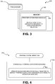
- FIG. 4 shows a flow chart 400 that implements examples of methods for printing an image on a substrate.
- Flow chart 400 includes, at block 402, to dynamically control a deposition sequence for depositing printing fluids (e.g., for treatment and ink) on a substrate location.
- Processor 104 may be responsible of implementing block 402 by accessing control data 114 (see FIGS. 1A ).
- Block 402 includes a sub-block 404 in which a sub-group of nozzles in the nozzle array arrangements are operated to deposit printing fluids onto the substrate according to the deposition sequence.
- the nozzles sub-groups are spatially selected to deposit the printing fluids onto the substrate according to the deposition sequence. More specifically, a nozzle sub-group corresponding to the fluid to be initially deposited can be selected to be spatially located downstream the sub-group corresponding to the fluid to be sub-sequentially deposited (downstream is with respect to the substrate advance direction).
- processor 104 may determine the deposition sequence. For example, it may receive a print mask in which it is specified the sequence into which ink and treatment is to be deposited on a substrate location. Processor 104 may then set the deposition sequence by selecting the nozzles sub-groups. Finally, processor 104 may cause generation of electrical signals into the actuation elements of the nozzles sub-groups to jet the print fluids according to the deposition sequence. Alternatively, processor 104 may receive instructions that indicate which deposition is to be determined. Processor 104 may then follow these instructions to generate or modify the printing mask according to the deposition sequence.
- printing system 100 can be used to implement a deposition sequence corresponding to firstly deposit treatment and subsequently deposit ink on substrate location 112a.
- processor 104 may select nozzle sub-group 110a, corresponding to treatment, to be located downstream of nozzle sub-group 108a, corresponding to ink, so that ink is deposited on treated substrate location 112.
- FIG. 1C printing system 100 can be used to implement a deposition sequence corresponding to firstly deposit ink and subsequently deposit treatment on substrate location 112a.
- processor 104 may selects nozzle sub-group 108a, corresponding to ink, to be located downstream of nozzle sub-group 110a, corresponding to treatment, so that treatment is deposited on inked substrate location 112. Further examples of dynamic control of different deposition sequences are illustrated with respect to FIGS. 6A to 6C .
- Methods for printing an image on a substrate may include setting a deposition sequence.
- Setting a deposition sequence as used herein refers to configure operation of a printing system, so that printing fluid (e.g., for treatment and ink) are deposited according to a specific deposition sequence.
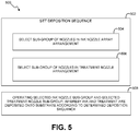
- FIG. 5 is a flow chart 500 that implements examples of methods for printing an image on a substrate, which in particular illustrate setting of a deposition sequence.
- printing fluids are illustrated to correspond to ink fluids and treatment fluids.
- the present disclosure is not limited to a specific selection of printing fluid but it encompasses control of deposition sequence of any printing fluid.
- a deposition sequence for depositing ink and treatment onto a substrate location is set.
- the deposition sequence can be set by selecting (i) a sub-group of nozzles in the ink nozzle array arrangement at sub-block 504, and (ii) selecting a sub-group of nozzles in the treatment nozzle array arrangement at sub-block 506. Thereby, the selection of nozzles sub-groups in the respective arrangements fixes the sequence into which treatment and ink are to be deposited on the substrate location.
- the selected nozzle sub-groups are operated, whereby ink and treatment are deposited on the substrate location according to the deposition sequence.
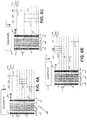
- FIGS. 6A-6C schematically show operation of a printing system (e.g., printing system 200 in FIG. 2A ) for depositing printing fluids according to different deposition sequences.
- the printing fluids correspond to ink and treatment, which includes a pretreatment PT and a post-treatment OC.
- Printhead 106 is shown to include ink nozzle array arrangement 108 and treatment nozzle array arrangement 110.
- ink nozzle array arrangement 108 includes four ink nozzle arrays 602a-602d for jetting, respectively, four different types of ink fluids (e.g., respectively corresponding to cyan, magenta, yellow, and black).
- Treatment nozzle arrangement 110 is shown to include a pre-treatment nozzle array 604 (e.g., corresponding to a fixer) and a post-treatment nozzle array 606 (e.g., corresponding to a coater).
- a sub-group of nozzles for each of the nozzle arrays is selected: a pre-treatment nozzle sub-group 608 is selected for pre-treatment nozzle array 604, an ink nozzle sub-group 610 is selected collectively for ink nozzle arrays 602a-602d, and a post-treatment nozzle sub-group 612 is selected for post-treatment nozzle array 606.
- the same ink nozzle sub-group 610 is selected in each of ink nozzle arrays 602a-602d. It will be understood that different ink nozzle sub-groups can be selected in ink nozzle arrays 602a-602d in order to modify deposition sequence of ink fluids.
- a selection of a nozzle sub-group results in a definition of a corresponding print swath.
- pre-treatment nozzle sub-group 608 defines a pre-treatment print swath 611
- ink nozzle sub-group 610 defines an ink print swath 614
- post-treatment nozzle sub-group 612 defines a post-treatment print swath 616.
- print swaths correspond to a multiple of a substrate advance length 622 (substrate advance is illustrated by parallel lines 620) in order to facilitate a convenient coverage of a substrate location with printing fluids.
- nozzle sub-groups 608, 610, 612 define print swaths corresponding to three times substrate advance length 622.
- Print swaths might correspond to any substrate advance multiple such as, but not limited to, one, two, four, or ten.
- FIG. 6A shows a printing operation in which printing fluids are to be deposited on a substrate location according to the following deposition sequence: first a pre-treatment fluid (e.g. a fixer), second ink fluids, and third a post-treatment fluid (e.g., a coating). Therefore, in this example, pre-treatment nozzle sub-group 608 is selected to be spatially located downstream of ink nozzle sub-group 610, and ink nozzle sub-group 610 is selected to be downstream of post-treatment nozzle sub-group 612 (downstream with respect to substrate advance direction 116).
- pre-treatment nozzle sub-group 608 is selected to be spatially located downstream of ink nozzle sub-group 610
- ink nozzle sub-group 610 is selected to be downstream of post-treatment nozzle sub-group 612 (downstream with respect to substrate advance direction 116).
- a deposition sequence is set in which (i) a substrate location firstly receives pretreatment for treating that substrate location before it receives ink, (ii) the treated substrate location receives ink thereon, and (iii) post-treatment (e.g., a coating) is applied on the inked location.
- post-treatment e.g., a coating
- the level of ink penetration when ink is deposited on a pretreated substrate location might be relatively low.
- nozzle subgroups are selected to set a deposition sequence in which ink is deposited on a substrate location before deposition of a pre-treatment (e.g., a fixer). Such examples are illustrated with respect to FIG. 6B .
- FIG. 6B shows a printing operation in which printing fluids are to be deposited on a substrate location according to the following deposition sequence: first ink fluids, second a pretreatment fluid (e.g. a fixer), and third a post-treatment fluid (e.g., a coating). Therefore, in this example, ink nozzle sub-group 610 is selected to be spatially located downstream of pretreatment nozzle sub-group 608, and pre-treatment nozzle sub-group 608 is selected to be downstream of post-treatment nozzle sub-group 612 (downstream with respect to substrate advance direction 116).
- first ink fluids e.g. a fixer
- third a post-treatment fluid e.g., a coating
- a deposition sequence is set in which, (i) the substrate location firstly receives ink, (ii) ink is allowed to penetrate into the substrate a during a certain time interval (this time interval is proportional to a gap 618 between ink nozzle sub-group 610 and pre-treatment nozzle sub-group 608, as further detailed below), and (iii), subsequently, a post-treatment is applied on deposited ink for, for example, coating of an ink pattern on the substrate.
- the deposition sequence is to quasi-simultaneously deposit printing fluids on a substrate location.
- the print swath can be enlarged in comparison to a simulated staggering as illustrated above and, therefore, printer speed might be improved.
- FIG. 6C A specific example of such an operation is illustrated with respect to FIG. 6C .
- ink and post-treatment are to be to be quasi-simultaneously deposited on a substrate location.
- ink nozzle sub-group 610 and post-treatment nozzle sub-group 612 are selected parallel to each other with equivalent dimensions so that ink and pre-treatment are deposited on a substrate location during the same transition of printhead 106. It will be understood that there is a certain delay between deposition of ink and post-treatment onto a specific substrate location. (This delay is due to the time required for positioning the respective nozzle arrays beneath the substrate location during printhead transition across the substrate width.)
- a time interval between depositions of different printing fluids on a substrate location can be defined by selection of a gap between the nozzles sub-groups with respect to substrate advance direction 116. More specifically, nozzle sub-groups may be selected such that there is a gap 618 between the nozzle sub-groups. The gap between nozzle sub-groups can be set to a multiple of a substrate advance. In FIG. 6A to 6C . (A printing system may be operated to advance substrate 112 a substrate advance length 622 before selected nozzles are fired). Gap 618 defines a time interval between depositions of printing fluids from selected nozzle sub-groups.
- gap 618 is defined between pre-treatment nozzle sub-group 608 and ink nozzle sub-group 610.
- gap 618 results in a time delay between laying down pre-treatment and ink deposition.
- Such a time modulation between pre-treatment and ink may be used to improve efficiency of the pretreatment on some substrate types in which the pre-treatment requires a certain time before ink deposition for achieving a desired effect.
- gap 618 is defined between ink nozzle sub-group 610 and pre-treatment nozzle sub-group 608.
- gap 618 results in a time delay between laying down ink and pre-treatment deposition.
- Such a time modulation between pretreatment and ink may be used to improve absorption of ink by the substrate before treating the ink on the substrate.
Landscapes
- Ink Jet (AREA)
- Ink Jet Recording Methods And Recording Media Thereof (AREA)
Applications Claiming Priority (1)
| Application Number | Priority Date | Filing Date | Title |
|---|---|---|---|
| PCT/EP2012/073959 WO2014082671A1 (en) | 2012-11-29 | 2012-11-29 | Operation of printing systems |
Publications (2)
| Publication Number | Publication Date |
|---|---|
| EP2925527A1 EP2925527A1 (en) | 2015-10-07 |
| EP2925527B1 true EP2925527B1 (en) | 2019-09-11 |
Family
ID=47297225
Family Applications (1)
| Application Number | Title | Priority Date | Filing Date |
|---|---|---|---|
| EP12797853.4A Not-in-force EP2925527B1 (en) | 2012-11-29 | 2012-11-29 | Operation of printing systems |
Country Status (5)
| Country | Link |
|---|---|
| US (2) | US9469125B2 (ja) |
| EP (1) | EP2925527B1 (ja) |
| JP (1) | JP6091640B2 (ja) |
| CN (1) | CN104812583B (ja) |
| WO (1) | WO2014082671A1 (ja) |
Families Citing this family (15)
| Publication number | Priority date | Publication date | Assignee | Title |
|---|---|---|---|---|
| JP6091640B2 (ja) * | 2012-11-29 | 2017-03-08 | ヒューレット−パッカード デベロップメント カンパニー エル.ピー.Hewlett‐Packard Development Company, L.P. | プリンティングシステムの動作 |
| JP6415080B2 (ja) * | 2014-04-11 | 2018-10-31 | キヤノン株式会社 | 画像処理装置、画像処理方法、記録装置及びプログラム |
| WO2016066225A1 (en) * | 2014-10-31 | 2016-05-06 | Hewlett-Packard Development Company, L.P. | Method of printing in a multipass mode and a printing apparatus for implementing such a method |
| JP6589319B2 (ja) * | 2015-03-23 | 2019-10-16 | セイコーエプソン株式会社 | 記録装置 |
| WO2017011004A1 (en) * | 2015-07-15 | 2017-01-19 | Hewlett-Packard Development Company, L.P. | Printer calibration |
| ES2677561T3 (es) * | 2015-07-20 | 2018-08-03 | Angelo Schiestl | Dispositivo y procedimiento para el pretratamiento y la impresión de superficies textiles |
| US10691988B2 (en) * | 2016-09-30 | 2020-06-23 | Hewlett-Packard Development Company, L.P. | Printing of a halftone based on multiple colorant deposition orders |
| JP6916292B2 (ja) | 2017-04-14 | 2021-08-11 | ヒューレット−パッカード デベロップメント カンパニー エル.ピー.Hewlett‐Packard Development Company, L.P. | 起動信号のための遅延要素 |
| WO2018190855A1 (en) | 2017-04-14 | 2018-10-18 | Hewlett-Packard Development Company, L.P. | Mask registers to store mask data patterns |
| US10994531B2 (en) | 2017-04-14 | 2021-05-04 | Hewlett-Packard Development Company, L.P. | Drop weights corresponding to drop weight patterns |
| US10882309B2 (en) * | 2017-07-25 | 2021-01-05 | Illinois Tool Works Inc. | Printing system and method |
| JP7035432B2 (ja) | 2017-09-29 | 2022-03-15 | ブラザー工業株式会社 | 前処理装置 |
| JP7027773B2 (ja) * | 2017-09-29 | 2022-03-02 | ブラザー工業株式会社 | 前処理装置 |
| JP7200704B2 (ja) * | 2019-01-31 | 2023-01-10 | セイコーエプソン株式会社 | 三次元造形装置および三次元造形物の造形方法 |
| US20230322007A1 (en) * | 2020-08-27 | 2023-10-12 | Hewlett-Packard Development Company, L.P. | Pre-treatment fluid application in printing systems |
Family Cites Families (16)
| Publication number | Priority date | Publication date | Assignee | Title |
|---|---|---|---|---|
| US6435639B1 (en) | 1998-04-27 | 2002-08-20 | Canon Kabushiki Kaisha | Ink jet recording method and ink jet recording apparatus |
| JP2000190476A (ja) | 1998-12-28 | 2000-07-11 | Canon Inc | 記録ヘッドおよび記録装置 |
| JP2001239660A (ja) * | 2000-02-29 | 2001-09-04 | Minolta Co Ltd | 立体物印刷装置および立体物印刷方法 |
| US6412935B1 (en) | 2000-05-16 | 2002-07-02 | Hewlett-Packard Company | Application of clear overcoat fluid |
| JP4827317B2 (ja) | 2001-04-26 | 2011-11-30 | キヤノン株式会社 | インクジェット記録方法およびインクジェット記録装置 |
| US7338143B2 (en) * | 2001-10-12 | 2008-03-04 | Seiko Epson Corporation | Ink jet recording apparatus and recording method of the recording apparatus |
| JP4989393B2 (ja) * | 2007-09-21 | 2012-08-01 | キヤノン株式会社 | インクジェット記録装置およびインクジェット記録方法 |
| JP5192335B2 (ja) | 2008-09-26 | 2013-05-08 | 富士フイルム株式会社 | インクジェット記録装置及び色補正方法 |
| JP2011001509A (ja) * | 2009-06-22 | 2011-01-06 | Air Water Inc | エポキシ(メタ)アクリレート樹脂、硬化性樹脂組成物およびその硬化物 |
| JP5636649B2 (ja) * | 2009-08-13 | 2014-12-10 | セイコーエプソン株式会社 | 流体噴射装置、及び、流体噴射方法 |
| JP5326924B2 (ja) * | 2009-08-18 | 2013-10-30 | セイコーエプソン株式会社 | 流体噴射装置、及び、流体噴射方法 |
| JP5560679B2 (ja) * | 2009-12-04 | 2014-07-30 | セイコーエプソン株式会社 | 流体噴射装置、及び、流体噴射方法 |
| US8511777B2 (en) * | 2009-08-13 | 2013-08-20 | Seiko Epson Corporation | Fluid ejecting apparatus and fluid ejecting method |
| JP5385185B2 (ja) * | 2010-03-23 | 2014-01-08 | 大日本スクリーン製造株式会社 | インクジェットプリンタおよび画像記録方法 |
| JP2012061784A (ja) * | 2010-09-17 | 2012-03-29 | Seiko Epson Corp | 液滴吐出装置及び液滴吐出方法 |
| JP6091640B2 (ja) * | 2012-11-29 | 2017-03-08 | ヒューレット−パッカード デベロップメント カンパニー エル.ピー.Hewlett‐Packard Development Company, L.P. | プリンティングシステムの動作 |
-
2012
- 2012-11-29 JP JP2015544364A patent/JP6091640B2/ja not_active Expired - Fee Related
- 2012-11-29 EP EP12797853.4A patent/EP2925527B1/en not_active Not-in-force
- 2012-11-29 CN CN201280077398.8A patent/CN104812583B/zh not_active Expired - Fee Related
- 2012-11-29 US US14/646,270 patent/US9469125B2/en active Active
- 2012-11-29 WO PCT/EP2012/073959 patent/WO2014082671A1/en active Application Filing
-
2016
- 2016-09-16 US US15/268,041 patent/US9873245B2/en active Active
Non-Patent Citations (1)
| Title |
|---|
| None * |
Also Published As
| Publication number | Publication date |
|---|---|
| WO2014082671A1 (en) | 2014-06-05 |
| EP2925527A1 (en) | 2015-10-07 |
| US20170008276A1 (en) | 2017-01-12 |
| US20150314615A1 (en) | 2015-11-05 |
| US9469125B2 (en) | 2016-10-18 |
| JP2016501748A (ja) | 2016-01-21 |
| US9873245B2 (en) | 2018-01-23 |
| CN104812583A (zh) | 2015-07-29 |
| CN104812583B (zh) | 2018-06-12 |
| JP6091640B2 (ja) | 2017-03-08 |
Similar Documents
| Publication | Publication Date | Title |
|---|---|---|
| US9873245B2 (en) | Operation of printing systems | |
| US20140232783A1 (en) | Printing Systems and Printing Methods | |
| EP2632729B1 (en) | Fluid ejection device with circulation pump | |
| EP1720709B1 (en) | Anharmonic stimulation of inkjet drop formation | |
| CN104853924B (zh) | 控制打印系统应用处理 | |
| CN103384600A (zh) | 打印系统和相关方法 | |
| EP3238138B1 (en) | Printer and method of controlling same | |
| US8985735B2 (en) | Deposition of print treatment | |
| US10207497B2 (en) | Selecting nozzles | |
| WO2013056748A1 (en) | Printing systems and methods | |
| US9327535B2 (en) | Print masks for multiple pass print modes | |
| CN102218910B (zh) | 液体喷射设备和控制设备 | |
| US9908328B2 (en) | Assigning firing reservations to primitives | |
| WO2017060902A1 (en) | Concealing missing nozzles | |
| US20160107438A1 (en) | Printer operation for ejection of purging droplets of a printing fluid | |
| JP6579817B2 (ja) | 記録装置、記録方法、及びコンピュータプログラム | |
| US20180022128A1 (en) | Random wave mask generation | |
| US20170372178A1 (en) | Method of printing and printer | |
| US11559984B2 (en) | Increasing temperatures of printing elements |
Legal Events
| Date | Code | Title | Description |
|---|---|---|---|
| PUAI | Public reference made under article 153(3) epc to a published international application that has entered the european phase |
Free format text: ORIGINAL CODE: 0009012 |
|
| 17P | Request for examination filed |
Effective date: 20150519 |
|
| AK | Designated contracting states |
Kind code of ref document: A1 Designated state(s): AL AT BE BG CH CY CZ DE DK EE ES FI FR GB GR HR HU IE IS IT LI LT LU LV MC MK MT NL NO PL PT RO RS SE SI SK SM TR |
|
| AX | Request for extension of the european patent |
Extension state: BA ME |
|
| DAX | Request for extension of the european patent (deleted) | ||
| STAA | Information on the status of an ep patent application or granted ep patent |
Free format text: STATUS: EXAMINATION IS IN PROGRESS |
|
| 17Q | First examination report despatched |
Effective date: 20180503 |
|
| RAP1 | Party data changed (applicant data changed or rights of an application transferred) |
Owner name: HEWLETT-PACKARD DEVELOPMENT COMPANY, L.P. |
|
| GRAP | Despatch of communication of intention to grant a patent |
Free format text: ORIGINAL CODE: EPIDOSNIGR1 |
|
| STAA | Information on the status of an ep patent application or granted ep patent |
Free format text: STATUS: GRANT OF PATENT IS INTENDED |
|
| INTG | Intention to grant announced |
Effective date: 20190613 |
|
| GRAS | Grant fee paid |
Free format text: ORIGINAL CODE: EPIDOSNIGR3 |
|
| GRAA | (expected) grant |
Free format text: ORIGINAL CODE: 0009210 |
|
| STAA | Information on the status of an ep patent application or granted ep patent |
Free format text: STATUS: THE PATENT HAS BEEN GRANTED |
|
| AK | Designated contracting states |
Kind code of ref document: B1 Designated state(s): AL AT BE BG CH CY CZ DE DK EE ES FI FR GB GR HR HU IE IS IT LI LT LU LV MC MK MT NL NO PL PT RO RS SE SI SK SM TR |
|
| REG | Reference to a national code |
Ref country code: GB Ref legal event code: FG4D |
|
| REG | Reference to a national code |
Ref country code: CH Ref legal event code: EP |
|
| REG | Reference to a national code |
Ref country code: AT Ref legal event code: REF Ref document number: 1177936 Country of ref document: AT Kind code of ref document: T Effective date: 20190915 |
|
| REG | Reference to a national code |
Ref country code: DE Ref legal event code: R096 Ref document number: 602012063935 Country of ref document: DE Ref country code: IE Ref legal event code: FG4D |
|
| REG | Reference to a national code |
Ref country code: NL Ref legal event code: MP Effective date: 20190911 |
|
| REG | Reference to a national code |
Ref country code: LT Ref legal event code: MG4D |
|
| PG25 | Lapsed in a contracting state [announced via postgrant information from national office to epo] |
Ref country code: FI Free format text: LAPSE BECAUSE OF FAILURE TO SUBMIT A TRANSLATION OF THE DESCRIPTION OR TO PAY THE FEE WITHIN THE PRESCRIBED TIME-LIMIT Effective date: 20190911 Ref country code: NO Free format text: LAPSE BECAUSE OF FAILURE TO SUBMIT A TRANSLATION OF THE DESCRIPTION OR TO PAY THE FEE WITHIN THE PRESCRIBED TIME-LIMIT Effective date: 20191211 Ref country code: LT Free format text: LAPSE BECAUSE OF FAILURE TO SUBMIT A TRANSLATION OF THE DESCRIPTION OR TO PAY THE FEE WITHIN THE PRESCRIBED TIME-LIMIT Effective date: 20190911 Ref country code: SE Free format text: LAPSE BECAUSE OF FAILURE TO SUBMIT A TRANSLATION OF THE DESCRIPTION OR TO PAY THE FEE WITHIN THE PRESCRIBED TIME-LIMIT Effective date: 20190911 Ref country code: BG Free format text: LAPSE BECAUSE OF FAILURE TO SUBMIT A TRANSLATION OF THE DESCRIPTION OR TO PAY THE FEE WITHIN THE PRESCRIBED TIME-LIMIT Effective date: 20191211 Ref country code: HR Free format text: LAPSE BECAUSE OF FAILURE TO SUBMIT A TRANSLATION OF THE DESCRIPTION OR TO PAY THE FEE WITHIN THE PRESCRIBED TIME-LIMIT Effective date: 20190911 |
|
| PG25 | Lapsed in a contracting state [announced via postgrant information from national office to epo] |
Ref country code: AL Free format text: LAPSE BECAUSE OF FAILURE TO SUBMIT A TRANSLATION OF THE DESCRIPTION OR TO PAY THE FEE WITHIN THE PRESCRIBED TIME-LIMIT Effective date: 20190911 Ref country code: GR Free format text: LAPSE BECAUSE OF FAILURE TO SUBMIT A TRANSLATION OF THE DESCRIPTION OR TO PAY THE FEE WITHIN THE PRESCRIBED TIME-LIMIT Effective date: 20191212 Ref country code: RS Free format text: LAPSE BECAUSE OF FAILURE TO SUBMIT A TRANSLATION OF THE DESCRIPTION OR TO PAY THE FEE WITHIN THE PRESCRIBED TIME-LIMIT Effective date: 20190911 Ref country code: LV Free format text: LAPSE BECAUSE OF FAILURE TO SUBMIT A TRANSLATION OF THE DESCRIPTION OR TO PAY THE FEE WITHIN THE PRESCRIBED TIME-LIMIT Effective date: 20190911 Ref country code: ES Free format text: LAPSE BECAUSE OF FAILURE TO SUBMIT A TRANSLATION OF THE DESCRIPTION OR TO PAY THE FEE WITHIN THE PRESCRIBED TIME-LIMIT Effective date: 20190911 |
|
| REG | Reference to a national code |
Ref country code: AT Ref legal event code: MK05 Ref document number: 1177936 Country of ref document: AT Kind code of ref document: T Effective date: 20190911 |
|
| PG25 | Lapsed in a contracting state [announced via postgrant information from national office to epo] |
Ref country code: IT Free format text: LAPSE BECAUSE OF FAILURE TO SUBMIT A TRANSLATION OF THE DESCRIPTION OR TO PAY THE FEE WITHIN THE PRESCRIBED TIME-LIMIT Effective date: 20190911 Ref country code: PL Free format text: LAPSE BECAUSE OF FAILURE TO SUBMIT A TRANSLATION OF THE DESCRIPTION OR TO PAY THE FEE WITHIN THE PRESCRIBED TIME-LIMIT Effective date: 20190911 Ref country code: AT Free format text: LAPSE BECAUSE OF FAILURE TO SUBMIT A TRANSLATION OF THE DESCRIPTION OR TO PAY THE FEE WITHIN THE PRESCRIBED TIME-LIMIT Effective date: 20190911 Ref country code: PT Free format text: LAPSE BECAUSE OF FAILURE TO SUBMIT A TRANSLATION OF THE DESCRIPTION OR TO PAY THE FEE WITHIN THE PRESCRIBED TIME-LIMIT Effective date: 20200113 Ref country code: EE Free format text: LAPSE BECAUSE OF FAILURE TO SUBMIT A TRANSLATION OF THE DESCRIPTION OR TO PAY THE FEE WITHIN THE PRESCRIBED TIME-LIMIT Effective date: 20190911 Ref country code: NL Free format text: LAPSE BECAUSE OF FAILURE TO SUBMIT A TRANSLATION OF THE DESCRIPTION OR TO PAY THE FEE WITHIN THE PRESCRIBED TIME-LIMIT Effective date: 20190911 Ref country code: RO Free format text: LAPSE BECAUSE OF FAILURE TO SUBMIT A TRANSLATION OF THE DESCRIPTION OR TO PAY THE FEE WITHIN THE PRESCRIBED TIME-LIMIT Effective date: 20190911 |
|
| PG25 | Lapsed in a contracting state [announced via postgrant information from national office to epo] |
Ref country code: CZ Free format text: LAPSE BECAUSE OF FAILURE TO SUBMIT A TRANSLATION OF THE DESCRIPTION OR TO PAY THE FEE WITHIN THE PRESCRIBED TIME-LIMIT Effective date: 20190911 Ref country code: IS Free format text: LAPSE BECAUSE OF FAILURE TO SUBMIT A TRANSLATION OF THE DESCRIPTION OR TO PAY THE FEE WITHIN THE PRESCRIBED TIME-LIMIT Effective date: 20200224 Ref country code: SM Free format text: LAPSE BECAUSE OF FAILURE TO SUBMIT A TRANSLATION OF THE DESCRIPTION OR TO PAY THE FEE WITHIN THE PRESCRIBED TIME-LIMIT Effective date: 20190911 Ref country code: SK Free format text: LAPSE BECAUSE OF FAILURE TO SUBMIT A TRANSLATION OF THE DESCRIPTION OR TO PAY THE FEE WITHIN THE PRESCRIBED TIME-LIMIT Effective date: 20190911 |
|
| REG | Reference to a national code |
Ref country code: DE Ref legal event code: R097 Ref document number: 602012063935 Country of ref document: DE |
|
| REG | Reference to a national code |
Ref country code: CH Ref legal event code: PL |
|
| PLBE | No opposition filed within time limit |
Free format text: ORIGINAL CODE: 0009261 |
|
| STAA | Information on the status of an ep patent application or granted ep patent |
Free format text: STATUS: NO OPPOSITION FILED WITHIN TIME LIMIT |
|
| PG2D | Information on lapse in contracting state deleted |
Ref country code: IS |
|
| PG25 | Lapsed in a contracting state [announced via postgrant information from national office to epo] |
Ref country code: DK Free format text: LAPSE BECAUSE OF FAILURE TO SUBMIT A TRANSLATION OF THE DESCRIPTION OR TO PAY THE FEE WITHIN THE PRESCRIBED TIME-LIMIT Effective date: 20190911 Ref country code: LU Free format text: LAPSE BECAUSE OF NON-PAYMENT OF DUE FEES Effective date: 20191129 Ref country code: LI Free format text: LAPSE BECAUSE OF NON-PAYMENT OF DUE FEES Effective date: 20191130 Ref country code: MC Free format text: LAPSE BECAUSE OF FAILURE TO SUBMIT A TRANSLATION OF THE DESCRIPTION OR TO PAY THE FEE WITHIN THE PRESCRIBED TIME-LIMIT Effective date: 20190911 Ref country code: CH Free format text: LAPSE BECAUSE OF NON-PAYMENT OF DUE FEES Effective date: 20191130 Ref country code: IS Free format text: LAPSE BECAUSE OF FAILURE TO SUBMIT A TRANSLATION OF THE DESCRIPTION OR TO PAY THE FEE WITHIN THE PRESCRIBED TIME-LIMIT Effective date: 20200112 |
|
| 26N | No opposition filed |
Effective date: 20200615 |
|
| REG | Reference to a national code |
Ref country code: BE Ref legal event code: MM Effective date: 20191130 |
|
| PG25 | Lapsed in a contracting state [announced via postgrant information from national office to epo] |
Ref country code: SI Free format text: LAPSE BECAUSE OF FAILURE TO SUBMIT A TRANSLATION OF THE DESCRIPTION OR TO PAY THE FEE WITHIN THE PRESCRIBED TIME-LIMIT Effective date: 20190911 |
|
| PG25 | Lapsed in a contracting state [announced via postgrant information from national office to epo] |
Ref country code: IE Free format text: LAPSE BECAUSE OF NON-PAYMENT OF DUE FEES Effective date: 20191129 |
|
| PG25 | Lapsed in a contracting state [announced via postgrant information from national office to epo] |
Ref country code: BE Free format text: LAPSE BECAUSE OF NON-PAYMENT OF DUE FEES Effective date: 20191130 |
|
| PG25 | Lapsed in a contracting state [announced via postgrant information from national office to epo] |
Ref country code: CY Free format text: LAPSE BECAUSE OF FAILURE TO SUBMIT A TRANSLATION OF THE DESCRIPTION OR TO PAY THE FEE WITHIN THE PRESCRIBED TIME-LIMIT Effective date: 20190911 |
|
| PG25 | Lapsed in a contracting state [announced via postgrant information from national office to epo] |
Ref country code: MT Free format text: LAPSE BECAUSE OF FAILURE TO SUBMIT A TRANSLATION OF THE DESCRIPTION OR TO PAY THE FEE WITHIN THE PRESCRIBED TIME-LIMIT Effective date: 20190911 Ref country code: HU Free format text: LAPSE BECAUSE OF FAILURE TO SUBMIT A TRANSLATION OF THE DESCRIPTION OR TO PAY THE FEE WITHIN THE PRESCRIBED TIME-LIMIT; INVALID AB INITIO Effective date: 20121129 |
|
| PGFP | Annual fee paid to national office [announced via postgrant information from national office to epo] |
Ref country code: GB Payment date: 20211020 Year of fee payment: 10 Ref country code: DE Payment date: 20211020 Year of fee payment: 10 |
|
| PGFP | Annual fee paid to national office [announced via postgrant information from national office to epo] |
Ref country code: FR Payment date: 20211020 Year of fee payment: 10 |
|
| PG25 | Lapsed in a contracting state [announced via postgrant information from national office to epo] |
Ref country code: TR Free format text: LAPSE BECAUSE OF FAILURE TO SUBMIT A TRANSLATION OF THE DESCRIPTION OR TO PAY THE FEE WITHIN THE PRESCRIBED TIME-LIMIT Effective date: 20190911 |
|
| PG25 | Lapsed in a contracting state [announced via postgrant information from national office to epo] |
Ref country code: MK Free format text: LAPSE BECAUSE OF FAILURE TO SUBMIT A TRANSLATION OF THE DESCRIPTION OR TO PAY THE FEE WITHIN THE PRESCRIBED TIME-LIMIT Effective date: 20190911 |
|
| REG | Reference to a national code |
Ref country code: DE Ref legal event code: R119 Ref document number: 602012063935 Country of ref document: DE |
|
| GBPC | Gb: european patent ceased through non-payment of renewal fee |
Effective date: 20221129 |
|
| PG25 | Lapsed in a contracting state [announced via postgrant information from national office to epo] |
Ref country code: GB Free format text: LAPSE BECAUSE OF NON-PAYMENT OF DUE FEES Effective date: 20221129 Ref country code: DE Free format text: LAPSE BECAUSE OF NON-PAYMENT OF DUE FEES Effective date: 20230601 |
|
| PG25 | Lapsed in a contracting state [announced via postgrant information from national office to epo] |
Ref country code: FR Free format text: LAPSE BECAUSE OF NON-PAYMENT OF DUE FEES Effective date: 20221130 |