EP2921615A1 - Pneumatisches Zelt, insbesondere Sternenzelt - Google Patents
Pneumatisches Zelt, insbesondere Sternenzelt Download PDFInfo
- Publication number
- EP2921615A1 EP2921615A1 EP14003918.1A EP14003918A EP2921615A1 EP 2921615 A1 EP2921615 A1 EP 2921615A1 EP 14003918 A EP14003918 A EP 14003918A EP 2921615 A1 EP2921615 A1 EP 2921615A1
- Authority
- EP
- European Patent Office
- Prior art keywords
- tent
- spar
- pneumatic
- particular star
- outer skin
- Prior art date
- Legal status (The legal status is an assumption and is not a legal conclusion. Google has not performed a legal analysis and makes no representation as to the accuracy of the status listed.)
- Granted
Links
- 238000005286 illumination Methods 0.000 claims abstract description 10
- 235000003332 Ilex aquifolium Nutrition 0.000 claims description 36
- 241000209027 Ilex aquifolium Species 0.000 claims description 36
- 239000002131 composite material Substances 0.000 claims description 7
- 230000000149 penetrating effect Effects 0.000 claims description 6
- 229920004934 Dacron® Polymers 0.000 claims description 4
- 238000005299 abrasion Methods 0.000 claims description 4
- 229920000728 polyester Polymers 0.000 claims description 4
- 239000005020 polyethylene terephthalate Substances 0.000 claims description 4
- 239000004576 sand Substances 0.000 claims description 4
- XLYOFNOQVPJJNP-UHFFFAOYSA-N water Substances O XLYOFNOQVPJJNP-UHFFFAOYSA-N 0.000 claims description 4
- 239000010410 layer Substances 0.000 description 17
- 238000010276 construction Methods 0.000 description 13
- 239000007789 gas Substances 0.000 description 12
- IJGRMHOSHXDMSA-UHFFFAOYSA-N Atomic nitrogen Chemical compound N#N IJGRMHOSHXDMSA-UHFFFAOYSA-N 0.000 description 6
- 239000002356 single layer Substances 0.000 description 6
- 239000000463 material Substances 0.000 description 4
- 238000009434 installation Methods 0.000 description 3
- 229910052757 nitrogen Inorganic materials 0.000 description 3
- 239000004814 polyurethane Substances 0.000 description 3
- XAGFODPZIPBFFR-UHFFFAOYSA-N aluminium Chemical compound [Al] XAGFODPZIPBFFR-UHFFFAOYSA-N 0.000 description 2
- 229910052782 aluminium Inorganic materials 0.000 description 2
- 229920002635 polyurethane Polymers 0.000 description 2
- 239000002023 wood Substances 0.000 description 2
- 241000234282 Allium Species 0.000 description 1
- 235000002732 Allium cepa var. cepa Nutrition 0.000 description 1
- 229920000049 Carbon (fiber) Polymers 0.000 description 1
- MYMOFIZGZYHOMD-UHFFFAOYSA-N Dioxygen Chemical compound O=O MYMOFIZGZYHOMD-UHFFFAOYSA-N 0.000 description 1
- 230000006978 adaptation Effects 0.000 description 1
- 230000002411 adverse Effects 0.000 description 1
- 239000004917 carbon fiber Substances 0.000 description 1
- 239000003795 chemical substances by application Substances 0.000 description 1
- 238000009792 diffusion process Methods 0.000 description 1
- 239000004744 fabric Substances 0.000 description 1
- 230000003993 interaction Effects 0.000 description 1
- 238000004519 manufacturing process Methods 0.000 description 1
- VNWKTOKETHGBQD-UHFFFAOYSA-N methane Chemical compound C VNWKTOKETHGBQD-UHFFFAOYSA-N 0.000 description 1
- 239000000203 mixture Substances 0.000 description 1
- 238000012856 packing Methods 0.000 description 1
- 230000001737 promoting effect Effects 0.000 description 1
- 210000002023 somite Anatomy 0.000 description 1
- 125000006850 spacer group Chemical group 0.000 description 1
- 230000000007 visual effect Effects 0.000 description 1
Images



Classifications
-
- E—FIXED CONSTRUCTIONS
- E04—BUILDING
- E04H—BUILDINGS OR LIKE STRUCTURES FOR PARTICULAR PURPOSES; SWIMMING OR SPLASH BATHS OR POOLS; MASTS; FENCING; TENTS OR CANOPIES, IN GENERAL
- E04H15/00—Tents or canopies, in general
- E04H15/20—Tents or canopies, in general inflatable, e.g. shaped, strengthened or supported by fluid pressure
-
- E—FIXED CONSTRUCTIONS
- E04—BUILDING
- E04H—BUILDINGS OR LIKE STRUCTURES FOR PARTICULAR PURPOSES; SWIMMING OR SPLASH BATHS OR POOLS; MASTS; FENCING; TENTS OR CANOPIES, IN GENERAL
- E04H12/00—Towers; Masts or poles; Chimney stacks; Water-towers; Methods of erecting such structures
- E04H12/22—Sockets or holders for poles or posts
- E04H12/2238—Sockets or holders for poles or posts to be placed on the ground
- E04H12/2246—Sockets or holders for poles or posts to be placed on the ground filled with water, sand or the like
-
- E—FIXED CONSTRUCTIONS
- E04—BUILDING
- E04H—BUILDINGS OR LIKE STRUCTURES FOR PARTICULAR PURPOSES; SWIMMING OR SPLASH BATHS OR POOLS; MASTS; FENCING; TENTS OR CANOPIES, IN GENERAL
- E04H15/00—Tents or canopies, in general
- E04H15/02—Tents combined or specially associated with other devices
- E04H15/10—Heating, lighting or ventilating
-
- E—FIXED CONSTRUCTIONS
- E04—BUILDING
- E04H—BUILDINGS OR LIKE STRUCTURES FOR PARTICULAR PURPOSES; SWIMMING OR SPLASH BATHS OR POOLS; MASTS; FENCING; TENTS OR CANOPIES, IN GENERAL
- E04H15/00—Tents or canopies, in general
- E04H15/24—Tents or canopies, in general cone shaped, e.g. teepees
-
- E—FIXED CONSTRUCTIONS
- E04—BUILDING
- E04H—BUILDINGS OR LIKE STRUCTURES FOR PARTICULAR PURPOSES; SWIMMING OR SPLASH BATHS OR POOLS; MASTS; FENCING; TENTS OR CANOPIES, IN GENERAL
- E04H15/00—Tents or canopies, in general
- E04H15/26—Centre-pole supported tents
-
- E—FIXED CONSTRUCTIONS
- E04—BUILDING
- E04H—BUILDINGS OR LIKE STRUCTURES FOR PARTICULAR PURPOSES; SWIMMING OR SPLASH BATHS OR POOLS; MASTS; FENCING; TENTS OR CANOPIES, IN GENERAL
- E04H15/00—Tents or canopies, in general
- E04H15/18—Tents having plural sectional covers, e.g. pavilions, vaulted tents, marquees, circus tents; Plural tents, e.g. modular
-
- E—FIXED CONSTRUCTIONS
- E04—BUILDING
- E04H—BUILDINGS OR LIKE STRUCTURES FOR PARTICULAR PURPOSES; SWIMMING OR SPLASH BATHS OR POOLS; MASTS; FENCING; TENTS OR CANOPIES, IN GENERAL
- E04H15/00—Tents or canopies, in general
- E04H15/32—Parts, components, construction details, accessories, interior equipment, specially adapted for tents, e.g. guy-line equipment, skirts, thresholds
- E04H15/60—Poles
-
- E—FIXED CONSTRUCTIONS
- E04—BUILDING
- E04H—BUILDINGS OR LIKE STRUCTURES FOR PARTICULAR PURPOSES; SWIMMING OR SPLASH BATHS OR POOLS; MASTS; FENCING; TENTS OR CANOPIES, IN GENERAL
- E04H15/00—Tents or canopies, in general
- E04H15/20—Tents or canopies, in general inflatable, e.g. shaped, strengthened or supported by fluid pressure
- E04H2015/201—Tents or canopies, in general inflatable, e.g. shaped, strengthened or supported by fluid pressure with inflatable tubular framework, with or without tent cover
-
- E—FIXED CONSTRUCTIONS
- E04—BUILDING
- E04H—BUILDINGS OR LIKE STRUCTURES FOR PARTICULAR PURPOSES; SWIMMING OR SPLASH BATHS OR POOLS; MASTS; FENCING; TENTS OR CANOPIES, IN GENERAL
- E04H15/00—Tents or canopies, in general
- E04H15/20—Tents or canopies, in general inflatable, e.g. shaped, strengthened or supported by fluid pressure
- E04H2015/209—Structures with a netting or similar for anchorage
Definitions
- Pneumatic tents are usually to be understood as inflatable tents and carrying tents, which are used wherever a simple and fast construction, a low transport weight, small packing dimensions and possibly an increased advertising effectiveness are of significant importance.
- these pneumatic tents are used only briefly, for example as a device tent on large construction sites, as a promotional pavilion, as a tent for military operations, as a medical tent, as emergency shelters, as housing for touring exhibitions, as a festival hostel or as a pavilion for sporting events.
- the first construction is immanent that the tent skin forming the shell of the tent is double-walled and divided into chambers, each chamber being inflated individually or several chambers in the composite.
- the construction differs from a breech block, which is supported by a positive pressure generated by a fan and has a correspondingly formed pressure lock for access.
- the frame construction with inflatable frame is called, in which the frame is at least partially wrapped by an additional tarpaulin as the outer skin.
- Such tent constructions are primarily in the camping, in the advertising industry and sports events their lovers because their functional design and visual appearance are virtually no limits and beyond for their construction no - often cumbersome to handle - linkage is needed.
- Star tents consist essentially of a single, usually made of aluminum or wood, vertically extending, centrally placed pillar and a tent skin, which extends like a dome over the culmination of the column and is distally tightened at several points by means of clamping elements and anchored to the ground ,
- the installation of such a column which naturally has a high weight with a standard length of 4m to 12 m, requires for assembly / disassembly at least two people, which inevitably entails organizational and financial costs.
- the object of the invention is now to propose a pneumatic tent, in particular star tent, which is particularly easy when Transport and assembly / disassembly by one person only.
- the pneumatic tent should have a greater functionality.
- the pneumatic tent in particular a star tent, at least one mounting end position starting from the footprint vertically extending spar and a self-supporting spar dome-like extending tent cover, which is locked with locking means against the footprint and tensioned, the one with overpressure charged filling gas having Holm is formed in one or more layers and has a controllable or controllable lighting device, which is placed within the spar.
- the individual layers are permanently connected to one another, for example in the form of a laminate, and / or lie layer-wise without composite on or against each other according to a so-called "onion skin construction".
- the multi-layered spar with layer-wise composite on or lying on each other layers preferably comprises a first layer, which is designed as a Holm the outer shape giving and acting as a support structure outer skin.
- a second layer is designed as a once filled filling gas reservoir trained inner tube with at least one outer skin penetrating valve, wherein the controllable or controllable illumination device is placed either within the inner tube designed as a fillable Gregasreservoir or between the inner tube and the outer skin.
- nitrogen preferably pure oxygen, nitrogen or a mixture thereof, or air
- nitrogen is of course fully available free of charge, it does
- pure nitrogen over air in which it is only partially present, has the advantage that it has larger molecules that are less prone to diffusion.
- a polyester for example Dacron, is preferably used as a material for the robust outer skin of the spar.
- the outer skin of the spar comprises an abrasion-resistant and mechanical force-resistant foot portion, a middle portion and a standing with the tent cover operatively connected head portion, wherein one or more sections locking means in the form of loops, rings, Velcro or eyelets, the spar over the footprint and on the other hand be able to attach functional elements in the form of bulbs, speakers, banners, brackets or controls on the spar.
- the cylinder-shaped spar is assigned a torus placed on the placement surface whose free cross-section is adapted to the cross-section of the spar, wherein the torus having the weighting means surrounds the foot portion of the spar in a ring-like manner and possibly coupled to the spar.
- a weighting agent for the torus while water or sand is provided, which are almost free of charge at almost every place of installation.
- the support structure of the spar is formed according to the invention by the outer skin made of polyester in interaction with the inner tube placed inside the outer skin, which is completely enveloped by the outer skin.
- the outer skin made of polyester in interaction with the inner tube placed inside the outer skin, which is completely enveloped by the outer skin.
- PU polyurethane
- Such a construction namely the construction of a support structure by means of a high-strength Dacron outer skin and an inner PU film, has proved to be particularly advantageous in countless series of experiments in order to be able to be used even under the most adverse weather conditions.
- Particularly useful is at least one formed in the foot and / or center section of the spar reservoir in which utensils for storage, for example, provided for disposable compressor compressor, power distribution, cables, a control and Regeleinecardi or provided as a replacement locking means are placed.
- utensils for storage for example, provided for disposable compressor compressor, power distribution, cables, a control and Regeleinecardi or provided as a replacement locking means are placed.
- the concept of the invention is also not opposed if the possibly closable reservoir is formed at a height of the spar in the region of the middle section, which corresponds to a user-friendly working height, i. H. between one meter and two meters, corresponds.
- a backlight illumination device of the spar on an adjusting and positioning device to the by means of cables or other conductive elements, for.
- LEDs coupled to each other within the spar exactly in height and in the spacing relative to the outer skin of the spar can.
- the adjusting and positioning device is designed such that it can also be operated in the final assembly position of the pneumatic tent.
- spacers, pulleys, spaced locking means and one or more thread trains are provided, which are in operative connection with each other.
- the spar has an outer skin giving it its outer shape and functioning as a support structure, and at least one inner tube formed as a once-filling gas reservoir with at least one valve penetrating the outer skin.
- the parallel design of the safety system ensures that in case of failure of an inner tube due to an unexpected drop in pressure of the other inner tubes or the ensure the required stability of the tent shell-bearing spar. This minimizes the risk of a common failure of all inner tubes placed in the spar.
- the at least one inner tube comprises a valve penetrating the outer skin, which is designed as an inlet valve with integrated suction-suction function. This means that by switching the flow direction, an inner tube inflated by means of an electric pump, compressed air cylinder or compressor can also be easily emptied or evacuated again.
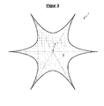
- FIGS. 1 to 3 show a front view, a perspective view and a top view of the pneumatic tent 1 according to the invention in a first embodiment with einlagig trained Holm 2.
- the trained as a typical star tent pneumatic tent 1 has in the example shown in a final assembly position starting from the footprint 8 vertically extending spar. 2 and on the self-supporting spar 2 dome-like extending tent cover 3, which is locked with locking means 4 relative to the footprint 8 and tensioned.
- Holm 2 is placed centrally relative to the tent cover 3, wherein the tent cover 3 spans over the culmination point 1.1 of the beam 2 like a dome.
- the one loaded with pressure filling gas spar 2 is formed in this example only a single layer.
- the single-layer spar 2 or the single-layer wall of the spar 2 gives the spar 2 the outer shape and acts by the introduced, under overpressure filling gas as a support structure.
- the tent cover 3 is constructed in several parts or segment-like, wherein the individual parts or segments are sewn together.
- the spar 2 further comprises an abrasion-resistant foot section 2.4, which is resistant to mechanical force, a middle section 2.5 and a head section 2.6 operatively connected to the tent cover 3.
- the detachable or temporary operative connection between the conically shaped head section 2.6 of the spar 2 and the tent cover 3 is realized by means of a hook-and-loop fastener.
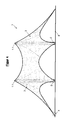
- FIGS. 4 to 6 show a front view, a perspective view and a top view of the pneumatic tent 1 according to the invention in a second embodiment with einlagig trained Holm 2.
- the trained as a typical star tent pneumatic tent 1 has in the illustrated example two in Montageendposition starting from the footprint 8 vertically extending spars 2 and on the two self-supporting spars 2 dome-like extending tent cover 3, which is locked with locking means 4 relative to the footprint 8 and tensioned.
- the two spars 2 are linear, ie placed on a common axis relative to the tent cover 3, wherein the tent cover 3 spans over the respective culmination points 1.1 of the spars 2 like a dome.
- the two each having an over-pressurized filling gas having spars 2 are formed in this example only one layer.
- the two single-layer spars 2 and the single-layer wall of each spar 2 give them the outer shape and act by the introduced, under pressure filling gas also as a support structure.
- the tent cover 3 is constructed in several parts or segment-like, wherein the individual parts or segments are sewn together.
- Each of the two spars 2 further includes an abrasion-resistant and resistant to mechanical force foot section 2.4, a middle section 2.5 and a standing with the tent cover 3 operatively connected head section 2.6.
- the detachable or temporary operative connection between the conically shaped head section 2.6 of each spar 2 and the tent cover 3 is in each case realized by means of a hook-and-loop fastener.
- the Fig. 7 illustrates a perspective view of the foot section 2.4 and center section 2.5 of a multi-layered spar 2, in which the individual layers in layers without composite or lie against each other.
- a first layer is designed as a hollow body 2 giving the outer shape and acting as a support structure outer skin 2.1 and a second layer is formed as a once fillable Golfgasreservoir trained inner tube 2.2 with at least one outer skin 2.1 penetrating valve 2.3.
- the controllable or controllable illumination device 5 is located, for example, within the inner tube 2.2 designed as a fillable filling gas reservoir.
- the inner tube 2.2 of each spar 2 is made of a stretchable PU and the outer skin 2.1 consists of a polyester fabric, here Dacron.
- Both the foot section 2.4 and the Center section 2.5 have locking means 4 in the form of only indicated loops, rings, hook-and-loop fasteners or eyelets in order to be able to attach the spar 2 to the set-up surface 8 and on the other hand functional elements in the form of bulbs, loudspeakers, banners, holders or controls on the spar 2.
- the center section 2.5 comprises a reservoir 7, in which utensils for storage, for example, provided for the disposable filling of the spar 2 compressor, power distribution, cables, a control and Regeleinecardi or provided as a replacement locking means 4 are placed.
- the multiple LED comprehensive and designed as a backlight illumination device 5 of the spar 2 has an adjusting and positioning device 5.1 to align the coupled by means of LEDs LEDs within the beam 2 exactly in height and in the distance from the outer skin 2.1 of the spar 2 can.
- the reference numeral indicates an on-off switch for a vertical lift device of the lighting device 5; Likewise, the on-off switch for the lighting device 5 can be arranged at this point.
- FIG. 8 is a detailed perspective view of a segmented torus 6 can be seen.
- the cylinder-shaped spar 2, see FIGS. 1 . 3 or 7 is preferably assigned to this placed on the footprint 8 torus 6, whose free cross-section is adapted to the cross-section of the spar 2, wherein the weighting torus 2 annularly surrounds the foot section 2.4 of the spar 2 and additionally coupled by means not shown lines with the spar 2 is and thus gives the spar 2 a sufficient stability.
- weighting means for the torus 6 water or sand is provided.
- the torus 6 may in this case consist of a dimensionally stable material supplied from the factory or be made of a material which forms its dimensional stability only after filling with sand or water.
Landscapes
- Engineering & Computer Science (AREA)
- Architecture (AREA)
- Civil Engineering (AREA)
- Structural Engineering (AREA)
- Physics & Mathematics (AREA)
- Fluid Mechanics (AREA)
- Tents Or Canopies (AREA)
Abstract
Description
- Unter pneumatischen Zelten sind üblicherweise aufblasbare Zelte und Tragluftzelte zu verstehen, die überall dort Einsatz finden, wo ein einfacher und schneller Aufbau, ein geringes Transportgewicht, kleine Packmaße und ggf. eine erhöhte Werbewirksamkeit von signifikanter Bedeutung sind.
- Häufig werden diese pneumatischen Zelte nur kurzzeitig, beispielsweise als Gerätezelt auf Großbaustellen, als Werbepavillon, als Einsatzzelt für militärische Operationen, als Sanitätszelt, als Notunterkünfte, als Behausung für Wanderausstellungen, als Festivalherberge oder als Pavillon für Sportevents eingesetzt.
- Für die Konstruktion pneumatischer Zelte konnten sich bislang drei grundlegende Bauweisen auf dem Markt durchsetzen, bei denen zur Aufrechterhaltung des erforderlichen Innendrucks diese entweder nur einmalig mit Luft befüllt und mittels Ventile verschlossen werden oder ein Gebläse/Kompressor permanent betrieben wird.
- Der ersten Konstruktion ist immanent, dass die die Hülle des Zeltes bildende Zelthaut dabei doppelwandig ausgebildet und in Kammern unterteilt ist, wobei jede Kammer einzeln oder mehrere Kammern im Verbund aufgeblasen werden.
- Von dieser doppelwandigen Konstruktion unterscheidet sich die Konstruktion eine Traglufthalle, welche von einem mittels Gebläse erzeugten Überdruck gestützt wird und eine entsprechend ausgebildete Druckschleuse für den Zugang hat.
- Letztlich sei die Rahmenbauweise mit aufblasbarem Rahmen genannt, bei der der Rahmen durch eine zusätzliche Zeltplane als Außenhaut zumindest partiell umhüllt ist. Derartige Zeltkonstruktionen finden vorrangig im Campingbereich, in der Werbebranche und bei Sportveranstaltungen ihre Liebhaber, da ihrer funktionellen Gestaltung und optischen Erscheinung nahezu keine Grenzen gesetzt sind und darüber hinaus für ihren Aufbau kein - oftmals nur umständlich zu handhabendes - Gestänge benötigt wird.
- Die Fertigungsgrenzen der letztgenannten Gattung von pneumatischen Zelten liegen jedoch dort, wo der Wunsch besteht, sogenannte Sternenzelte als rein pneumatische Zelte dem Markt zur Verfügung zu stellen. Sternenzelte unterscheiden sich von anderen Zelten dadurch, dass sie eine größere Bauhöhe haben und somit ein angenehmeres "Raumgefühl" für die Benutzer vermitteln.
- Sternezelte bestehen nämlich im Wesentlichen aus einer einzelnen, meist aus Aluminium oder Holz gefertigten, vertikal sich erstreckenden, zentral platzierten Säule sowie einer Zelthaut, die sich kuppelartig über den Kulminationspunkt der Säule erstreckt und distal an mehreren Stellen mittels Spannelemente abgespannt und dabei am Boden verankert wird. Die Montage einer solchen Säule, die bei einer üblichen Baulänge von 4m bis 12 m naturgemäß ein hohes Eigengewicht aufweist, erfordert zur Montage/Demontage mindestens zwei Personen, was zwangsläufig organisatorischen und finanziellen Aufwand nach sich zieht.
- Mit den derzeit am Markt verfügbaren Lösungen ist es bislang nicht möglich, die schwere, zentrisch platzierte Aluminium- oder Holzsäule gegen eine leichter zu handhabende Konstruktion zu substituieren.
- Die Aufgabe der Erfindung besteht nunmehr darin ein pneumatisches Zelt, insbesondere Sternenzelt vorzuschlagen, welches besonders einfach beim Transport und bei der Montage/Demontage nur durch eine Person zu handhaben. Darüber hinaus soll das pneumatische Zelt eine größere Funktionalität aufweisen.
- Erfindungsgemäß weist das pneumatische Zelt, insbesondere ein Sternenzelt, zumindest einen in Montageendposition ausgehend von der Aufstellfläche sich vertikal erstreckenden Holm sowie eine über den selbsttragenden Holm kuppelartig sich erstreckende Zelthülle auf, die mit Arretierungsmitteln gegenüber der Aufstellfläche arretiert und gespannt wird, wobei der ein mit Überdruck beaufschlagtes Füllgas aufweisende Holm einlagig oder mehrlagig ausgebildet ist und eine steuerbare oder regelbare Beleuchtungseinrichtung aufweist, die innerhalb des Holms platziert ist.
- Bei einem mehrlagig ausgebildeten Holm sind die einzelnen Lagen dauerhaft miteinander, beispielsweise in Gestalt eines Laminats, verbunden und/oder liegen schichtweise ohne Verbund auf- oder aneinander gemäß einer sogenannten "Zwiebelhautkonstruktion".
- Der mehrlagig ausgebildete Holm mit schichtweise ohne Verbund auf- oder aneinander liegenden Lagen umfasst vorzugsweise eine erste Lage, die als eine dem Holm die äußere Form gebende und als Stützstruktur fungierende Außenhaut ausgebildet ist. Eine zweite Lage ist als einmal befüllbares Füllgasreservoir ausgebildeter Innenschlauch mit zumindest einem die Außenhaut durchdringenden Ventil ausgebildet, wobei die steuerbare oder regelbare Beleuchtungseinrichtung entweder innerhalb des als befüllbares Füllgasreservoir ausgebildeten Innenschlauchs oder zwischen dem Innenschlauch und der Außenhaut platziert ist.
- Als Füllgase werden vorzugsweise reiner Sauerstoff, Stickstoff oder ein Gemisch daraus, respektive Luft, eingesetzt. Luft steht im Gegensatz zu Stickstoff zwar naturgemäß uneingeschränkt kostenlos zur Verfügung, doch weist reiner Stickstoff gegenüber Luft, in welchem dieser nur anteilig vorhanden ist, den Vorteil auf, dass es größere Moleküle hat, die weniger zur Diffusion neigen.
- Bei einer bevorzugten Ausgestaltung der Erfindung wird jedoch nur ein relativ zur Zelthülle zentrisch platzierter Holm eingesetzt, über dessen Kulminationspunkt sich die Zelthülle kuppelartig aufspannt. Die äußere Form ähnelt dabei der Form eines nordamerikanischen Indianerzeltes, respektive eines Tipi. Ferner besteht auch die Möglichkeit, zwei Holme vorzusehen, welche dann eingesetzt werden, wenn der Wunsch der Nutzer nach einer größeren "überdachten" Zeltfläche besteht.
- Mit dieser Lösung steht dem Markt erstmals ein pneumatisches Sternenzelt zur Verfügung, bei dem nicht nur die Zelthülle sondern auch der zumindest eine illuminierte Holm, neben seiner Funktion als tragendes Element, als hinterleuchtete Werbefläche genutzt werden kann ohne die Notwendigkeit, zur Aufrechterhaltung des Innendrucks ein Gebläse permanent betreiben zu müssen.
- Als Material für die robuste Außenhaut des Holms wird vorzugsweise ein Polyester, beispielsweise Dacron, eingesetzt.
- Die Außenhaut des Holms umfasst einen abriebfesten und gegen mechanische Krafteinwirkung beständigen Fußabschnitt, einen Mittenabschnitt sowie einen mit der Zelthülle in Wirkverbindung stehenden Kopfabschnitt, wobei einer oder mehrere Abschnitte Arretierungsmittel in Gestalt von Schlaufen, Ringen, Klettverschlüssen oder Ösen aufweisen, um den Holm gegenüber der Aufstellfläche und andererseits Funktionalelemente in Gestalt von Leuchtmitteln, Lautsprechern, Werbebannern, Halterungen oder Bedienelementen am Holm befestigen zu können.
- Es hat sich als besonders vorteilhaft erwiesen, wenn die Wirkverbindung zwischen dem konisch ausgebildeten Kopfabschnitt des Holms und der Zelthülle mittels Klettverschluss realisiert wird.
- Um dem Holm in Montageendposition eine hinreichend gute Standsicherheit zu verleihen ist vorgesehen, dass dem zylinderförmig ausgebildeten Holm ein auf der Aufstellfläche platzierter Torus zugeordnet ist, dessen freier Querschnitt passfähig zum Querschnitt des Holms ausgebildet ist, wobei der Beschwerungsmittel aufweisende Torus ringartig den Fußabschnitt des Holmes umschließt und ggf. mit dem Holm gekoppelt ist. Als Beschwerungsmittel für den Torus ist dabei Wasser oder Sand vorgesehen, die nahezu an jedem Aufstellort in der Regel kostenlos zur Verfügung stehen.
- Die Stützstruktur des Holms wird erfindungsgemäß gebildet durch die aus Polyester gefertigte Außenhaut im Zusammenspiel mit dem innerhalb der Außenhaut platzierten Innenschlauch, der vollständig von der Außenhaut umhüllt ist. Zur Sicherstellung einer optimalen Anpassung des aufgeblasenen Innenschlauchs an die Außenhaut wird als Werkstoff vorzugsweise Polyurethan (PU) in Gestalt einer Folie eingesetzt.
- Eine derartige Konstruktion, nämlich der Aufbau einer Stützstruktur mittels einer hochfesten Dacron-Außenhaut und einer innenliegenden PU-Folie, hat sich in unzähligen Versuchsreihen als besonders vorteilhaft erwiesen, um auch unter widrigsten Wetterbedingungen eingesetzt werden zu können.
- Für ausgewählte Anwendungsfälle des Erfindungsgegenstandes hat sich erfolgreich bewährt, die Zelthülle und/oder die Außenhaut des Holms mehrteilig oder segmentartig auszubilden, wobei die einzelnen Teile oder Segmente miteinander vernäht, verklebt, verschweißt oder mittels Klettverbindung miteinander verbunden sind.
- Besonders praktisch erweist sich zumindest ein im Fußabschnitt und/oder Mittenabschnitt des Holms ausgebildetes Reservoir, in welchem Utensilien zur Ablage, beispielsweise der zur Einmalbefüllung vorgesehene Kompressor, Stromverteiler, Kabel, eine Steuer- und Regeleinerichtung oder als Ersatz vorgesehene Arretierungsmittel platziert sind. Dem Erfindungsgedanken steht auch nicht entgegen, wenn das ggf. verschließbare Reservoir in einer Höhe des Holms im Bereich des Mittenabschnitts ausgebildet ist, welche einer benutzerfreundlichen Arbeitshöhe, d. h. zwischen einem Meter und zwei Meter, entspricht.
- Vorzugsweise weist die mehrere LED umfassende und als Hinterleuchtung ausgebildete Beleuchtungseinrichtung des Holms eine Justier- und Positionierungseinrichtung auf, um die mittels Kabel oder anderen leitfähigen Elementen, z. B. Kohlefaser, miteinander gekoppelten LEDs innerhalb des Holms exakt in der Höhe und in der Beabstandung gegenüber der Außenhaut des Holms ausrichten zu können. Die Justier- und Positionierungseinrichtung ist dabei derart ausgebildet, dass sie auch in Montageendposition des pneumatischen Zelts bedient werden kann. Im einfachsten Fall sind dazu Abstandshalter, Umlenkrollen, voneinander beabstandete Arretierungsmittel und ein oder mehrere Fadenzüge vorgesehen, die miteinander in Wirkverbindung stehen.
- Wie bereits erwähnt, weist der Holm eine ihm die äußere Form gebende und als Stützstruktur fungierende Außenhaut und zumindest einen als einmal befüllbares Füllgasreservoir ausgebildeten Innenschlauch mit zumindest einem die Außenhaut durchdringenden Ventil auf. Aus Gründen der Ausfall-, Funktions- und Betriebssicherheit kann es jedoch auch zweckmäßig sein, mehrere parallel verlaufende Innenschläuche vorzusehen, um eine gewünschte Redundanz zu erzeugen. Die parallele Auslegung des sicherheitstechnischen Systems gewährleistet, dass bei Ausfall eines Innenschlauchs infolge eines unerwarteten Druckluftabfalls der oder die anderen Innenschläuche die erforderliche Stabilität des die Zelthülle tragenden Holms gewährleisten. Dadurch wird das Risiko einer gemeinsamen Störung aller im Holm platzierten Innenschläuche minimiert.
- Der zumindest eine Innenschlauch umfasst ein die Außenhaut durchdringendes Ventil, welches als Einlassventil mit integrierter Rücksaugfunktion ausgebildet ist. Das heißt, dass durch Umschaltung der Strömungsrichtung ein mittels Elektropumpe, Druckluftflasche oder Kompressor aufgepumpter Innenschlauch auch problemlos wieder entleert bzw. evakuiert werden kann.
- Die signifikanten Vorteile und Merkmale der Erfindung gegenüber dem Stand der Technik sind im Wesentlichen:
- kompaktes pneumatisches Zelt mit großer Funktionalität, welches besonders einfach beim Transport und bei der Montage/Demontage nur durch eine Person zu handhaben ist,
- pneumatisches Zelt besteht aus zumindest einem selbstragenden Holm und einer kuppelartig über den Holm sich erstreckenden Zelthülle, wobei der ein mit Überdruck beaufschlagtes Füllgas aufweisende Holm einlagig oder mehrlagig ausgebildet ist und eine steuerbare oder regelbare Beleuchtungseinrichtung aufweist, die innerhalb des Holms platziert ist,
- bei einem mehrlagig ausgebildeten Holm sind die einzelnen Lagen dauerhaft miteinander, beispielsweise in Gestalt eines Laminats, verbunden und/oder liegen schichtweise ohne Verbund auf- oder aneinander,
- bei einem mehrlagig ausgebildeten Holm mit schichtweise ohne Verbund auf- oder aneinander liegenden Lagen ist eine erste Lage als eine dem Holm die äußere Form gebende und als Stützstruktur fungierende Außenhaut eine zweite Lage als einmal befüllbares Füllgasreservoir ausgebildeter Innenschlauch mit zumindest einem die Außenhaut durchdringenden Ventil ausgebildet, wobei die steuerbare oder regelbare Beleuchtungseinrichtung entweder innerhalb des als befüllbares Füllgasreservoir ausgebildeten Innenschlauchs oder zwischen dem Innenschlauch und der Außenhaut platziert ist,
- nicht nur die Zelthülle, sondern auch der illuminierte Holm kann neben seiner Funktion als tragendes Element auch als hinterleuchtete Werbefläche genutzt werden,
- der Holm ist als Einmalbefüllsystem ausgebildet ohne die Notwendigkeit, zur Aufrechterhaltung des Innendrucks ein Gebläse permanent betreiben zu müssen,
- Zelthülle und Holm sind nur temporär miteinander fixiert und stehen ausschließlich durch eine Klettverbindung miteinander in Eingriff, wodurch eine Austauschbarkeit aus verschiedenen Gründen problemlos realisiert werden kann,
- einer oder mehrere Abschnitte des Holms umfassen Arretierungsmittel in Gestalt von Schlaufen, Ringen, Klettverschlüssen oder Ösen, um einerseits den Holm gegenüber der Aufstellfläche und andererseits Funktionalelemente in Gestalt von Leuchtmitteln, Lautsprechern, Werbebannern, Halterungen oder Bedienelementen am Holm befestigen zu können,
- dem zylinderförmig ausgebildeten Holm ist ein auf der Aufstellfläche platzierter Torus zugeordnet, dessen freier Querschnitt passfähig zum Querschnitt des Holmes ausgebildet ist, wobei der Beschwerungsmittel aufweisende Torus ringartig den Fußabschnitt des Holmes umschließt und ggf. mit dem Holm gekoppelt ist und somit dem Holm eine hinreichende Standsicherheit verleiht und
- die Beleuchtungseinrichtung ist als Hinterleuchtung ausgebildet, die innerhalb des als befüllbares Füllgasreservoir ausgebildeten Innenschlauchs oder zwischen dem Innenschlauch und der Außenhaut platziert ist.
- Die zuvor erläuterten Merkmale und Vorteile dieser Erfindung sind nach sorgfältigem Studium der nachfolgenden ausführlichen Beschreibung der hier bevorzugten, nicht einschränkenden Beispielausgestaltungen der Erfindung mit den zugehörigen Zeichnungen besser zu verstehen und zu bewerten, welche zeigen:
- Fig. 1:
- eine Frontansicht des pneumatischen Zelts in einer ersten Ausgestaltung mit einlagig ausgebildetem Holm,
- Fig. 2:
- eine perspektivische Ansicht des pneumatischen Zelts in einer ersten Ausgestaltung mit einlagig ausgebildetem Holm,
- Fig. 3:
- eine Draufsicht auf das pneumatische Zelt in einer ersten Ausgestaltung mit einlagig ausgebildetem Holm,
- Fig. 4:
- eine Frontansicht des pneumatischen Zelts in einer zweiten Ausgestaltung mit einlagig ausgebildetem Holm,
- Fig. 5:
- eine perspektivische Ansicht des pneumatischen Zelts in einer zweiten Ausgestaltung mit einlagig ausgebildetem Holm,
- Fig. 6:
- eine Draufsicht auf das pneumatische Zelt in einer zweiten Ausgestaltung mit einlagig ausgebildetem Holm,
- Fig. 7:
- eine perspektivische Darstellung des Fußabschnitts und Mittenabschnitts eines mehrlagig ausgebildeten Holms und
- Fig. 8:
- eine perspektivische Detaildarstellung des Torus.
- Die
Figuren 1 bis 3 zeigen eine Frontansicht, eine perspektivische Ansicht und eine Draufsicht des erfindungsgemäßen pneumatischen Zelts 1 in einer ersten Ausgestaltung mit einlagig ausgebildetem Holm 2. Das als typisches Sternenzelt ausgebildete pneumatische Zelt 1 weist im dargestellten Beispiel einen in Montageendposition ausgehend von der Aufstellfläche 8 sich vertikal erstreckenden Holm 2 sowie eine über den selbsttragenden Holm 2 kuppelartig sich erstreckende Zelthülle 3 auf, die mit Arretierungsmitteln 4 gegenüber der Aufstellfläche 8 arretiert und gespannt wird. Der hier einzig verwendete Holm 2 ist relativ zur Zelthülle 3 zentrisch platziert, wobei die Zelthülle 3 sich über den Kulminationspunkt 1.1 des Holms 2 kuppelartig aufspannt. Der ein mit Überdruck beaufschlagtes Füllgas aufweisende Holm 2 ist in diesem Beispiel nur einlagig ausgebildet. Der einlagige Holm 2 bzw. die einlagige Wandung des Holms 2 verleiht dem Holm 2 die äußere Form und fungiert durch das eingebrachte, unter Überdruck stehende Füllgas auch als Stützstruktur. Wie ersichtlich, ist die Zelthülle 3 mehrteilig oder segmentartig aufgebaut, wobei die einzelnen Teile oder Segmente miteinander vernäht sind. Der Holm 2 umfasst ferner einen abriebfesten und gegen mechanische Krafteinwirkung beständigen Fußabschnitt 2.4, einen Mittenabschnitt 2.5 sowie einen mit der Zelthülle 3 in Wirkverbindung stehenden Kopfabschnitt 2.6. Die lösbare bzw. temporäre Wirkverbindung zwischen dem konisch ausgebildeten Kopfabschnitt 2.6 des Holms 2 und der Zelthülle 3 ist mittels eines Klettverschlusses realisiert. - Die
Figuren 4 bis 6 zeigen eine Frontansicht, eine perspektivische Ansicht und eine Draufsicht des erfindungsgemäßen pneumatischen Zelts 1 in einer zweiten Ausgestaltung mit einlagig ausgebildetem Holm 2. Das als typisches Sternenzelt ausgebildete pneumatische Zelt 1 weist im dargestellten Beispiel zwei in Montageendposition ausgehend von der Aufstellfläche 8 sich vertikal erstreckende Holme 2 sowie eine über die beiden selbsttragenden Holme 2 kuppelartig sich erstreckende Zelthülle 3 auf, die mit Arretierungsmitteln 4 gegenüber der Aufstellfläche 8 arretiert und gespannt wird. Die beiden Holme 2 sind dabei linear, d. h. auf einer gemeinsamen Achse relativ zur Zelthülle 3 platziert, wobei die Zelthülle 3 sich über die jeweiligen Kulminationspunkte 1.1 der Holme 2 kuppelartig aufspannt. Die beiden jeweils ein mit Überdruck beaufschlagtes Füllgas aufweisenden Holme 2 sind in diesem Beispiel jeweils nur einlagig ausgebildet. Die beiden einlagigen Holme 2 bzw. die einlagige Wandung jedes Holms 2 verleihen ihnen die äußere Form und fungieren durch das eingebrachte, unter Überdruck stehende Füllgas auch als Stützstruktur. Wie ersichtlich, ist die Zelthülle 3 mehrteilig oder segmentartig aufgebaut, wobei die einzelnen Teile oder Segmente miteinander vernäht sind. Jeder der beiden Holme 2 umfasst jeweils ferner einen abriebfesten und gegen mechanische Krafteinwirkung beständigen Fußabschnitt 2.4, einen Mittenabschnitt 2.5 sowie einen mit der Zelthülle 3 in Wirkverbindung stehenden Kopfabschnitt 2.6. Die lösbare bzw. temporäre Wirkverbindung zwischen dem konisch ausgebildeten Kopfabschnitt 2.6 jedes Holms 2 und der Zelthülle 3 ist jeweils mittels eines Klettverschlusses realisiert. - Die
Fig. 7 illustriert eine perspektivische Darstellung des Fußabschnitts 2.4 und Mittenabschnitts 2.5 eines mehrlagig ausgebildeten Holms 2, bei dem die einzelnen Lagen schichtweise ohne Verbund auf- oder aneinander liegen. Eine erste Lage ist dabei als eine dem Holm 2 die äußere Form gebende und als Stützstruktur fungierende Außenhaut 2.1 und eine zweite Lage ist als einmal befüllbares Füllgasreservoir ausgebildeter Innenschlauch 2.2 mit zumindest einem die Außenhaut 2.1 durchdringenden Ventil 2.3 ausgebildet. Die steuerbare oder regelbare Beleuchtungseinrichtung 5 befindet sich exemplarisch innerhalb des als befüllbares Füllgasreservoir ausgebildeten Innenschlauchs 2.2. Der Innenschlauch 2.2 jedes Holms 2 ist aus einer dehnbaren PU-gefertigt und die Außenhaut 2.1 besteht aus einem Polyestergewebe, hier Dacron. Sowohl der Fußabschnitt 2.4 als auch der Mittenabschnitt 2.5 weisen Arretierungsmittel 4 in Gestalt von nur angedeuteten Schlaufen, Ringen, Klettverschlüssen oder Ösen auf, um einerseits den Holm 2 gegenüber der Aufstellfläche 8 und andererseits Funktionalelemente in Gestalt von Leuchtmitteln, Lautsprechern, Werbebannern, Halterungen oder Bedienelementen am Holm 2 befestigen zu können. Der Mittenabschnitt 2.5 umfasst ein Reservoir 7, in welchem Utensilien zur Ablage, beispielsweise der zur Einmalbefüllung des Holms 2 vorgesehene Kompressor, Stromverteiler, Kabel, eine Steuer- und Regeleinerichtung oder als Ersatz vorgesehene Arretierungsmittel 4 platziert sind. Die mehrere LED umfassende und als Hinterleuchtung ausgebildete Beleuchtungseinrichtung 5 des Holms 2 weist eine Justier- und Positionierungseinrichtung 5.1 auf, um die mittels Kabel miteinander gekoppelten LEDs innerhalb des Holms 2 exakt in der Höhe und in der Beabstandung gegenüber der Außenhaut 2.1 des Holms 2 ausrichten zu können. In der dargestelltenFig. 7 zeigt das Bezugszeichen auf einen Ein- und Ausschalter für eine Vertikalaufzugseinrichtung der Beleuchtungseinrichtung 5; ebenso kann an dieser Stelle der Ein- und Ausschalter für die Beleuchtungseinrichtung 5 angeordnet sein. - Aus der
Fig. 8 ist eine perspektivische Detaildarstellung eines segmentartig aufgebauten Torus 6 zu entnehmen. Dem zylinderförmig ausgebildeten Holm 2, sieheFiguren 1 ,3 oder7 , ist vorzugsweise dieser auf der Aufstellfläche 8 platzierte Torus 6 zugeordnet, dessen freier Querschnitt passfähig zum Querschnitt des Holms 2 ausgebildet ist, wobei der Beschwerungsmittel aufweisende Torus 2 ringartig den Fußabschnitt 2.4 des Holms 2 umschließt und zusätzlich mittels nicht dargestellter Leinen mit dem Holm 2 gekoppelt ist und somit dem Holm 2 eine hinreichende Standsicherheit verleiht. Als Beschwerungsmittel für den Torus 6 ist Wasser oder Sand vorgesehen. Der Torus 6 kann hierbei aus einem werkseitig gelieferten formstabilen Material bestehen oder aus einem Material gefertigt sein, welches erst nach dem Befüllen mit Sand oder Wasser seine Formstabilität ausbildet. -
- 1
- Pneumatisches Zelt
- 1.1
- Kulminationspunkt
- 2
- Holm
- 2.1
- Außenhaut
- 2.2
- Innenschlauch
- 2.3
- Ventil
- 2.4
- Fußabschnitt
- 2.5
- Mittenabschnitt
- 2.6
- Kopfabschnitt
- 3
- Zelthülle
- 4
- Arretierungsmittel
- 5
- Beleuchtungseinrichtung
- 5.1
- Justier- und Positionierungseinrichtung
- 6
- Torus
- 7
- Reservoir
- 8
- Aufstellfläche
Claims (13)
- Pneumatisches Zelt (1), insbesondere Sternenzelt, aufweisend zumindest einen in Montageendposition ausgehend von der Aufstellfläche (8) sich vertikal erstreckenden Holm (2) sowie eine über den selbstragenden Holm (2) kuppelartig sich erstreckende Zelthülle (3), die mit Arretierungsmitteln (4) gegenüber der Aufstellfläche (8) arretiert und gespannt wird, wobei der ein mit Überdruck beaufschlagtes Füllgas aufweisende Holm (2) einlagig oder mehrlagig ausgebildet ist und eine steuerbare oder regelbare Beleuchtungseinrichtung (5) aufweist, die innerhalb des Holms (2) platziert ist.
- Pneumatisches Zelt (1), insbesondere Sternenzelt, nach Anspruch 1, dadurch gekennzeichnet, dass bei einem mehrlagig ausgebildeten Holm (2) die einzelnen Lagena. dauerhaft miteinander, beispielsweise in Gestalt eines Laminats, verbunden und/oderb. schichtweise ohne Verbund auf- oder aneinander liegen.
- Pneumatisches Zelt (1), insbesondere Sternenzelt, nach Anspruch 1 oder 2, dadurch gekennzeichnet, dass bei einem mehrlagig ausgebildeten Holm (2) mit schichtweise ohne Verbund auf- oder aneinander liegenden Lagena. eine erste Lage als eine dem Holm (2) die äußere Form gebende und als Stützstruktur fungierende Außenhaut (2.1) undb. eine zweite Lage als einmal befüllbares Füllgasreservoir ausgebildeter Innenschlauch (2.2) mit zumindest einem die Außenhaut durchdringenden Ventil (2.3) ausgebildet ist,wobei die steuerbare oder regelbare Beleuchtungseinrichtung (5) entweder innerhalb des als befüllbares Füllgasreservoir ausgebildeten Innenschlauchs (2.2) oder zwischen dem Innenschlauch (2.2) und der Außenhaut (2.1) platziert ist.
- Pneumatisches Zelt (1), insbesondere Sternenzelt, nach einem der Ansprüche 1 bis 3, dadurch gekennzeichnet, dass bei Verwendung von nur einem Holm (2) die Zelthülle (3) sich über den Kulminationspunkt (1.1) des relativ zur Zelthülle (3) zentrisch platzierten Holms (2) kuppelartig aufspannt.
- Pneumatisches Zelt (1), insbesondere Sternenzelt, nach Anspruch 3 oder 4, dadurch gekennzeichnet, dass die Außenhaut (2.1) des Holms (2) aus Polyester, beispielsweise Dacron, besteht.
- Pneumatisches Zelt (1), insbesondere Sternenzelt, nach einem der Ansprüche 3 bis 5, dadurch gekennzeichnet, dass die Außenhaut (2.1) des Holms (2) einen abriebfesten und gegen mechanische Krafteinwirkung beständigen Fußabschnitt (2.4), einen Mittenabschnitt (2.5) sowie einen mit der Zelthülle (3) in Wirkverbindung stehenden Kopfabschnitt (2.6) umfasst, wobei einer oder mehrere Abschnitte (2.4-2.6) Arretierungsmittel (4) in Gestalt von Schlaufen, Ringen, Klettverschlüssen oder Ösen aufweisen, um einerseits den Holm (2) gegenüber der Aufstellfläche (8) und andererseits Funktionalelemente in Gestalt von Leuchtmitteln, Lautsprechern, Werbebannern, Halterungen oder Bedienelementen am Holm (2) befestigen zu können.
- Pneumatisches Zelt (1), insbesondere Sternenzelt, nach Anspruch 6, dadurch gekennzeichnet, dass die Wirkverbindung zwischen dem konisch ausgebildeten Kopfabschnitt (2.6) des Holms (2) und der Zelthülle (3) mittels Klettverschluss realisiert ist.
- Pneumatisches Zelt (1), insbesondere Sternenzelt, nach einem der Ansprüche 1 bis 7, dadurch gekennzeichnet, dass dem zylinderförmig ausgebildeten Holm (2) ein auf der Aufstellfläche (8) platzierter Torus (6) zugeordnet ist, dessen freier Querschnitt passfähig zum Querschnitt des Holmes (2) ausgebildet ist, wobei der Beschwerungsmittel aufweisende Torus (6) ringartig den Fußabschnitt (2.4) des Holms (2) umschließt und ggf. mit dem Holm (2) gekoppelt ist und somit dem Holm (2) eine hinreichende Standsicherheit verleiht.
- Pneumatisches Zelt (1), insbesondere Sternenzelt, nach einem der Ansprüche 1 bis 8, dadurch gekennzeichnet, dass als Beschwerungsmittel für den Torus (6) Wasser oder Sand vorgesehen ist.
- Pneumatisches Zelt (1), insbesondere Sternenzelt, nach einem der Ansprüche 1 bis 9, dadurch gekennzeichnet, dass der Innenschlauch (2.2) des Holms (2) aus einer dehnbaren PU-Folie besteht.
- Pneumatisches Zelt (1), insbesondere Sternenzelt, nach einem der Ansprüche 1 bis 10, dadurch gekennzeichnet, dass die Zelthülle (3) und/oder die Außenhaut (2.1) des Holms (2) mehrteilig oder segmentartig aufgebaut ist/sind, wobei die einzelnen Teile oder Segmente miteinander vernäht, verklebt, verschweißt oder mittels Klettverbindung miteinander verbunden sind.
- Pneumatisches Zelt (1), insbesondere Sternenzelt, nach einem der Ansprüche 6 bis 11, dadurch gekennzeichnet, dass der Fußabschnitt (2.4) und/oder der Mittenabschnitt (2.5) zumindest ein Reservoir (7) aufweist, in welchem Utensilien zur Ablage, beispielsweise der zur Einmalbefüllung vorgesehene Kompressor, Stromverteiler, Kabel, eine Steuer- und Regeleinerichtung oder als Ersatz vorgesehene Arretierungsmittel (4) platziert sind.
- Pneumatisches Zelt (1), insbesondere Sternenzelt, nach einem der Ansprüche 1 bis 12, dadurch gekennzeichnet, dass die mehrere LED umfassende und als Hinterleuchtung ausgebildete Beleuchtungseinrichtung (5) des Holms (2) eine Justier- und Positionierungseinrichtung (5.1) aufweist, um die mittels Kabel miteinander gekoppelten LEDs innerhalb des Holms (2) exakt in der Höhe und in der Beabstandung gegenüber der Außenhaut (2.1) des Holms (2) ausrichten zu können.
Applications Claiming Priority (1)
| Application Number | Priority Date | Filing Date | Title |
|---|---|---|---|
| DE202014002481.2U DE202014002481U1 (de) | 2014-03-21 | 2014-03-21 | Pneumatisches Zelt, insbesondere Sternenzelt |
Publications (2)
| Publication Number | Publication Date |
|---|---|
| EP2921615A1 true EP2921615A1 (de) | 2015-09-23 |
| EP2921615B1 EP2921615B1 (de) | 2016-04-06 |
Family
ID=50821818
Family Applications (1)
| Application Number | Title | Priority Date | Filing Date |
|---|---|---|---|
| EP14003918.1A Not-in-force EP2921615B1 (de) | 2014-03-21 | 2014-11-21 | Pneumatisches Zelt, insbesondere Sternenzelt |
Country Status (3)
| Country | Link |
|---|---|
| US (1) | US9803387B2 (de) |
| EP (1) | EP2921615B1 (de) |
| DE (1) | DE202014002481U1 (de) |
Families Citing this family (16)
| Publication number | Priority date | Publication date | Assignee | Title |
|---|---|---|---|---|
| USD962376S1 (en) * | 2015-12-01 | 2022-08-30 | Mark Andrew Fraser | Portable shelter frame |
| US20190066573A1 (en) * | 2017-08-28 | 2019-02-28 | Spencer I. Hochberg | Load-bearing interactive pole video display system |
| USD884815S1 (en) * | 2018-08-09 | 2020-05-19 | Jianfeng Hu | Portable tent |
| USD907155S1 (en) * | 2019-01-25 | 2021-01-05 | Earl Senchuk | Open-top tent |
| USD934554S1 (en) * | 2019-02-20 | 2021-11-02 | Aksimo Distribution Ltd. | Umbrella base weight bag |
| USD919955S1 (en) * | 2019-02-20 | 2021-05-25 | Amiram Kohen | Umbrella base weight bag |
| USD919282S1 (en) * | 2019-02-21 | 2021-05-18 | Amiram Kohen | Umbrella base weight bag set |
| USD985094S1 (en) * | 2020-08-25 | 2023-05-02 | Boutique Camping Supplies Limited | Tent |
| FR3114114A1 (fr) * | 2020-09-16 | 2022-03-18 | Vitabri | Construction à couverture souple avec mât central lumineux équipé de LED |
| DE102021112115A1 (de) | 2021-04-09 | 2022-10-13 | X GLOO GmbH & Co. KG | Textile Raumstruktur und Verfahren zum Herstellen einer textilen Raumstruktur |
| USD972062S1 (en) * | 2021-05-13 | 2022-12-06 | Shenzhen Dream Journey Travel Products Co., Ltd. | Tent |
| USD1016330S1 (en) * | 2021-05-25 | 2024-02-27 | Andrea LYNN BROUWERS | Shade structure |
| AU2022206698B9 (en) | 2021-07-20 | 2024-05-30 | Andrea Lynn BROUWERS | Portable wind resistant shade structure |
| GB2615070B (en) | 2022-01-19 | 2025-08-27 | Purple Line Ltd | Camping assembly |
| USD1077964S1 (en) * | 2022-10-13 | 2025-06-03 | Zhejiang Hengfeng Top Leisure Co., Ltd. | Tent |
| FR3142206B1 (fr) * | 2022-11-22 | 2024-11-29 | Michelin & Cie | Structure gonflable et procede de fabrication d’une structure gonflable |
Citations (5)
| Publication number | Priority date | Publication date | Assignee | Title |
|---|---|---|---|---|
| FR2248381A1 (en) * | 1973-10-19 | 1975-05-16 | Chateau Stephane Du | Method of erecting a collapsible circular building - involves raising roof ring with pivotal struts using inflatable column |
| DE20010038U1 (de) * | 2000-06-07 | 2000-08-31 | Pommerenke, Herbert, 79232 March | Zeltartige Vorrichtung zum Unterstellen, insbesondere Umkleidekabine |
| NL1023734C2 (nl) * | 2003-06-24 | 2004-12-28 | Albert Veraart | Opblaasbare semi-permanente structuur met borgmiddelen. |
| CN201666031U (zh) * | 2010-03-24 | 2010-12-08 | 赵馨雨 | 充气帐篷 |
| CN202767617U (zh) * | 2012-09-25 | 2013-03-06 | 浙江理工大学 | 带照明功能的水上帐篷 |
Family Cites Families (23)
| Publication number | Priority date | Publication date | Assignee | Title |
|---|---|---|---|---|
| US3234685A (en) | 1964-04-02 | 1966-02-15 | Ideal Toy Corp | Inflatable self-mounting toy |
| US3415475A (en) * | 1966-10-13 | 1968-12-10 | Robert R. Goodman | Weighted base |
| US4068418A (en) * | 1976-06-11 | 1978-01-17 | Masse Jean Pierre | Collapsible shelter |
| US4179832A (en) * | 1976-12-29 | 1979-12-25 | Lemelson Jerome H | Inflatable displays |
| US4537210A (en) * | 1981-04-06 | 1985-08-27 | Montgomery Rodney L | Shelter |
| US4655008A (en) | 1985-12-19 | 1987-04-07 | The B. F. Goodrich Company | Inflatable shelter lift bag |
| US5036874A (en) * | 1988-11-09 | 1991-08-06 | Lynch James P | Tensioned tent structure and erection method therefor |
| US5234011A (en) * | 1991-08-02 | 1993-08-10 | Lynch James P | Clear span tent structure |
| US5421128A (en) | 1994-01-14 | 1995-06-06 | Sharpless; Garrett C. | Curved, inflated, tubular beam |
| US5918614A (en) * | 1994-01-18 | 1999-07-06 | Lynch; James P. | Configurable shade structure including a kit and method therefor |
| US5477876A (en) * | 1994-02-07 | 1995-12-26 | Bill Moss, Inc. | T-pole support for fabric structure |
| US5482374A (en) * | 1994-02-28 | 1996-01-09 | Innovision, Inc. | Beach towel/carry bag |
| US5555679A (en) * | 1994-10-24 | 1996-09-17 | Scherba; Robert | Inflatable device |
| ITVE980007U1 (it) | 1998-03-16 | 1999-09-16 | Medici Guido | Kit di illuminazione di emergenza con struttura gonfiata con aria sof fiante |
| US6192633B1 (en) * | 1999-09-10 | 2001-02-27 | Clint J. Hilbert | Rapidly deployable protective enclosure |
| JP2002194925A (ja) * | 2000-12-25 | 2002-07-10 | Mizuho Sewing Machine Kk | 簡易設営テント |
| US20100200038A1 (en) * | 2001-06-04 | 2010-08-12 | Roman Kendyl A | Blind with structure for rapid setup |
| FR2839577B1 (fr) * | 2002-05-10 | 2005-06-03 | Jean Luc Pellecuer | Dispositif de support de communication |
| US20040050411A1 (en) * | 2002-09-13 | 2004-03-18 | Buster Lawrence | Inflatable shelter |
| CA2590070A1 (en) * | 2007-05-25 | 2008-11-25 | Thomas Appleton | Inflatable portable lamp |
| EP2655764A4 (de) * | 2010-12-20 | 2017-01-25 | Doble, Simon | Beleuchteter pfosten |
| US8789549B1 (en) * | 2011-09-01 | 2014-07-29 | William Rogers Barnes | Portable canopy anchoring device and system |
| US9125467B2 (en) * | 2013-07-24 | 2015-09-08 | Advanced Promotional Technologies, Inc. | Canopy assembly organizer |
-
2014
- 2014-03-21 DE DE202014002481.2U patent/DE202014002481U1/de not_active Expired - Lifetime
- 2014-11-21 EP EP14003918.1A patent/EP2921615B1/de not_active Not-in-force
- 2014-12-29 US US14/584,682 patent/US9803387B2/en not_active Expired - Fee Related
Patent Citations (5)
| Publication number | Priority date | Publication date | Assignee | Title |
|---|---|---|---|---|
| FR2248381A1 (en) * | 1973-10-19 | 1975-05-16 | Chateau Stephane Du | Method of erecting a collapsible circular building - involves raising roof ring with pivotal struts using inflatable column |
| DE20010038U1 (de) * | 2000-06-07 | 2000-08-31 | Pommerenke, Herbert, 79232 March | Zeltartige Vorrichtung zum Unterstellen, insbesondere Umkleidekabine |
| NL1023734C2 (nl) * | 2003-06-24 | 2004-12-28 | Albert Veraart | Opblaasbare semi-permanente structuur met borgmiddelen. |
| CN201666031U (zh) * | 2010-03-24 | 2010-12-08 | 赵馨雨 | 充气帐篷 |
| CN202767617U (zh) * | 2012-09-25 | 2013-03-06 | 浙江理工大学 | 带照明功能的水上帐篷 |
Also Published As
| Publication number | Publication date |
|---|---|
| EP2921615B1 (de) | 2016-04-06 |
| US20150267436A1 (en) | 2015-09-24 |
| DE202014002481U1 (de) | 2014-05-08 |
| US9803387B2 (en) | 2017-10-31 |
Similar Documents
| Publication | Publication Date | Title |
|---|---|---|
| EP2921615B1 (de) | Pneumatisches Zelt, insbesondere Sternenzelt | |
| EP2554477B1 (de) | Flugzeug mit mindestens einem Gebilde zur Raumunterteilung | |
| DE2108262A1 (de) | Aufpumpbare Umkleidung und Verfahren zum Aufrichten derselben | |
| EP1665204A1 (de) | Werbeträger | |
| DE102020129159A1 (de) | Raumstruktur | |
| DE3029465C2 (de) | ||
| DE2053702C3 (de) | Aufblasbares und ganz oder teilweise einziehbares Schutzdach | |
| EP1191168A2 (de) | Vorzelt mit aufblasbarem Gerüst | |
| DE29610682U1 (de) | Zeltbett | |
| DE202013008404U1 (de) | Mobile Beleuchtungsvorrichtung | |
| DE2225784A1 (de) | Aufblasbares Bauwerk | |
| DE10064873B4 (de) | Vakuumauftriebskörper | |
| DE102021109798A1 (de) | Mobiles Bauwerk | |
| DE29707584U1 (de) | Umhauste Anlage | |
| DE4411491C2 (de) | Verfahren zur Herstellung einer räumlichen gewölbten Konstruktion und Stützvorrichtung zur Durchführung des Verfahrens | |
| DE20114974U1 (de) | Luftkammersystem für Zelte | |
| DE1559112A1 (de) | Selbsttragendes aufblasbares Zelt | |
| EP1630472A2 (de) | Mit Luft aufblasbarer Ballon für Beleuchtungszwecke | |
| DE10332986A1 (de) | Selbsttragende Membrankonstruktion | |
| DE2213869A1 (de) | Tragluftkonstruktion mit einem waermeisolierenden mantel | |
| EP4545735A1 (de) | Mobiles bauwerk | |
| AT18297U1 (de) | Aufblasbarer Sonnenschirm | |
| AT413614B (de) | Halterung für ein plakat | |
| DE9416047U1 (de) | Aufblasbarer Ausstellungsstand | |
| DE4421080A1 (de) | Großraumzelt |
Legal Events
| Date | Code | Title | Description |
|---|---|---|---|
| PUAI | Public reference made under article 153(3) epc to a published international application that has entered the european phase |
Free format text: ORIGINAL CODE: 0009012 |
|
| AK | Designated contracting states |
Kind code of ref document: A1 Designated state(s): AL AT BE BG CH CY CZ DE DK EE ES FI FR GB GR HR HU IE IS IT LI LT LU LV MC MK MT NL NO PL PT RO RS SE SI SK SM TR |
|
| AX | Request for extension of the european patent |
Extension state: BA ME |
|
| 17P | Request for examination filed |
Effective date: 20150910 |
|
| RBV | Designated contracting states (corrected) |
Designated state(s): AL AT BE BG CH CY CZ DE DK EE ES FI FR GB GR HR HU IE IS IT LI LT LU LV MC MK MT NL NO PL PT RO RS SE SI SK SM TR |
|
| GRAP | Despatch of communication of intention to grant a patent |
Free format text: ORIGINAL CODE: EPIDOSNIGR1 |
|
| RIC1 | Information provided on ipc code assigned before grant |
Ipc: E04H 15/10 20060101AFI20151027BHEP Ipc: E04H 15/24 20060101ALI20151027BHEP Ipc: E04H 15/20 20060101ALI20151027BHEP Ipc: E04H 15/26 20060101ALI20151027BHEP Ipc: E04H 12/22 20060101ALI20151027BHEP Ipc: E04H 15/18 20060101ALI20151027BHEP Ipc: E04H 15/60 20060101ALI20151027BHEP |
|
| INTG | Intention to grant announced |
Effective date: 20151203 |
|
| GRAS | Grant fee paid |
Free format text: ORIGINAL CODE: EPIDOSNIGR3 |
|
| GRAA | (expected) grant |
Free format text: ORIGINAL CODE: 0009210 |
|
| AK | Designated contracting states |
Kind code of ref document: B1 Designated state(s): AL AT BE BG CH CY CZ DE DK EE ES FI FR GB GR HR HU IE IS IT LI LT LU LV MC MK MT NL NO PL PT RO RS SE SI SK SM TR |
|
| REG | Reference to a national code |
Ref country code: GB Ref legal event code: FG4D Free format text: NOT ENGLISH |
|
| REG | Reference to a national code |
Ref country code: AT Ref legal event code: REF Ref document number: 788030 Country of ref document: AT Kind code of ref document: T Effective date: 20160415 Ref country code: CH Ref legal event code: EP |
|
| REG | Reference to a national code |
Ref country code: IE Ref legal event code: FG4D Free format text: LANGUAGE OF EP DOCUMENT: GERMAN |
|
| REG | Reference to a national code |
Ref country code: DE Ref legal event code: R096 Ref document number: 502014000546 Country of ref document: DE |
|
| REG | Reference to a national code |
Ref country code: NL Ref legal event code: FP |
|
| REG | Reference to a national code |
Ref country code: SE Ref legal event code: TRGR |
|
| REG | Reference to a national code |
Ref country code: LT Ref legal event code: MG4D |
|
| REG | Reference to a national code |
Ref country code: NO Ref legal event code: T2 Effective date: 20160406 |
|
| REG | Reference to a national code |
Ref country code: NO Ref legal event code: CREP Representative=s name: ONSAGERS AS, POSTBOKS 1813 VIKA, 0123 OSLO, NORGE |
|
| PG25 | Lapsed in a contracting state [announced via postgrant information from national office to epo] |
Ref country code: FI Free format text: LAPSE BECAUSE OF FAILURE TO SUBMIT A TRANSLATION OF THE DESCRIPTION OR TO PAY THE FEE WITHIN THE PRESCRIBED TIME-LIMIT Effective date: 20160406 Ref country code: PL Free format text: LAPSE BECAUSE OF FAILURE TO SUBMIT A TRANSLATION OF THE DESCRIPTION OR TO PAY THE FEE WITHIN THE PRESCRIBED TIME-LIMIT Effective date: 20160406 Ref country code: IS Free format text: LAPSE BECAUSE OF FAILURE TO SUBMIT A TRANSLATION OF THE DESCRIPTION OR TO PAY THE FEE WITHIN THE PRESCRIBED TIME-LIMIT Effective date: 20160806 Ref country code: LT Free format text: LAPSE BECAUSE OF FAILURE TO SUBMIT A TRANSLATION OF THE DESCRIPTION OR TO PAY THE FEE WITHIN THE PRESCRIBED TIME-LIMIT Effective date: 20160406 |
|
| REG | Reference to a national code |
Ref country code: CH Ref legal event code: NV Representative=s name: BRAUNPAT BRAUN EDER AG, CH |
|
| REG | Reference to a national code |
Ref country code: FR Ref legal event code: PLFP Year of fee payment: 3 |
|
| PG25 | Lapsed in a contracting state [announced via postgrant information from national office to epo] |
Ref country code: PT Free format text: LAPSE BECAUSE OF FAILURE TO SUBMIT A TRANSLATION OF THE DESCRIPTION OR TO PAY THE FEE WITHIN THE PRESCRIBED TIME-LIMIT Effective date: 20160808 Ref country code: RS Free format text: LAPSE BECAUSE OF FAILURE TO SUBMIT A TRANSLATION OF THE DESCRIPTION OR TO PAY THE FEE WITHIN THE PRESCRIBED TIME-LIMIT Effective date: 20160406 Ref country code: GR Free format text: LAPSE BECAUSE OF FAILURE TO SUBMIT A TRANSLATION OF THE DESCRIPTION OR TO PAY THE FEE WITHIN THE PRESCRIBED TIME-LIMIT Effective date: 20160707 Ref country code: LV Free format text: LAPSE BECAUSE OF FAILURE TO SUBMIT A TRANSLATION OF THE DESCRIPTION OR TO PAY THE FEE WITHIN THE PRESCRIBED TIME-LIMIT Effective date: 20160406 Ref country code: ES Free format text: LAPSE BECAUSE OF FAILURE TO SUBMIT A TRANSLATION OF THE DESCRIPTION OR TO PAY THE FEE WITHIN THE PRESCRIBED TIME-LIMIT Effective date: 20160406 Ref country code: HR Free format text: LAPSE BECAUSE OF FAILURE TO SUBMIT A TRANSLATION OF THE DESCRIPTION OR TO PAY THE FEE WITHIN THE PRESCRIBED TIME-LIMIT Effective date: 20160406 |
|
| PG25 | Lapsed in a contracting state [announced via postgrant information from national office to epo] |
Ref country code: IT Free format text: LAPSE BECAUSE OF FAILURE TO SUBMIT A TRANSLATION OF THE DESCRIPTION OR TO PAY THE FEE WITHIN THE PRESCRIBED TIME-LIMIT Effective date: 20160406 |
|
| REG | Reference to a national code |
Ref country code: DE Ref legal event code: R097 Ref document number: 502014000546 Country of ref document: DE |
|
| PG25 | Lapsed in a contracting state [announced via postgrant information from national office to epo] |
Ref country code: RO Free format text: LAPSE BECAUSE OF FAILURE TO SUBMIT A TRANSLATION OF THE DESCRIPTION OR TO PAY THE FEE WITHIN THE PRESCRIBED TIME-LIMIT Effective date: 20160406 Ref country code: SK Free format text: LAPSE BECAUSE OF FAILURE TO SUBMIT A TRANSLATION OF THE DESCRIPTION OR TO PAY THE FEE WITHIN THE PRESCRIBED TIME-LIMIT Effective date: 20160406 Ref country code: DK Free format text: LAPSE BECAUSE OF FAILURE TO SUBMIT A TRANSLATION OF THE DESCRIPTION OR TO PAY THE FEE WITHIN THE PRESCRIBED TIME-LIMIT Effective date: 20160406 Ref country code: EE Free format text: LAPSE BECAUSE OF FAILURE TO SUBMIT A TRANSLATION OF THE DESCRIPTION OR TO PAY THE FEE WITHIN THE PRESCRIBED TIME-LIMIT Effective date: 20160406 Ref country code: CZ Free format text: LAPSE BECAUSE OF FAILURE TO SUBMIT A TRANSLATION OF THE DESCRIPTION OR TO PAY THE FEE WITHIN THE PRESCRIBED TIME-LIMIT Effective date: 20160406 |
|
| PLBE | No opposition filed within time limit |
Free format text: ORIGINAL CODE: 0009261 |
|
| STAA | Information on the status of an ep patent application or granted ep patent |
Free format text: STATUS: NO OPPOSITION FILED WITHIN TIME LIMIT |
|
| PG25 | Lapsed in a contracting state [announced via postgrant information from national office to epo] |
Ref country code: BE Free format text: LAPSE BECAUSE OF NON-PAYMENT OF DUE FEES Effective date: 20161130 Ref country code: SM Free format text: LAPSE BECAUSE OF FAILURE TO SUBMIT A TRANSLATION OF THE DESCRIPTION OR TO PAY THE FEE WITHIN THE PRESCRIBED TIME-LIMIT Effective date: 20160406 |
|
| 26N | No opposition filed |
Effective date: 20170110 |
|
| PG25 | Lapsed in a contracting state [announced via postgrant information from national office to epo] |
Ref country code: SI Free format text: LAPSE BECAUSE OF FAILURE TO SUBMIT A TRANSLATION OF THE DESCRIPTION OR TO PAY THE FEE WITHIN THE PRESCRIBED TIME-LIMIT Effective date: 20160406 |
|
| REG | Reference to a national code |
Ref country code: IE Ref legal event code: MM4A |
|
| PG25 | Lapsed in a contracting state [announced via postgrant information from national office to epo] |
Ref country code: LU Free format text: LAPSE BECAUSE OF NON-PAYMENT OF DUE FEES Effective date: 20161130 |
|
| REG | Reference to a national code |
Ref country code: FR Ref legal event code: PLFP Year of fee payment: 4 |
|
| PG25 | Lapsed in a contracting state [announced via postgrant information from national office to epo] |
Ref country code: IE Free format text: LAPSE BECAUSE OF NON-PAYMENT OF DUE FEES Effective date: 20161121 |
|
| REG | Reference to a national code |
Ref country code: DE Ref legal event code: R082 Ref document number: 502014000546 Country of ref document: DE Representative=s name: PATENTANWAELTE TOBIAS KOEHLER UND VOLKMAR MUEL, DE |
|
| REG | Reference to a national code |
Ref country code: BE Ref legal event code: MM Effective date: 20161130 |
|
| REG | Reference to a national code |
Ref country code: CH Ref legal event code: PCAR Free format text: NEW ADDRESS: HOLEESTRASSE 87, 4054 BASEL (CH) |
|
| PG25 | Lapsed in a contracting state [announced via postgrant information from national office to epo] |
Ref country code: HU Free format text: LAPSE BECAUSE OF FAILURE TO SUBMIT A TRANSLATION OF THE DESCRIPTION OR TO PAY THE FEE WITHIN THE PRESCRIBED TIME-LIMIT; INVALID AB INITIO Effective date: 20141121 |
|
| PG25 | Lapsed in a contracting state [announced via postgrant information from national office to epo] |
Ref country code: CY Free format text: LAPSE BECAUSE OF FAILURE TO SUBMIT A TRANSLATION OF THE DESCRIPTION OR TO PAY THE FEE WITHIN THE PRESCRIBED TIME-LIMIT Effective date: 20160406 Ref country code: MK Free format text: LAPSE BECAUSE OF FAILURE TO SUBMIT A TRANSLATION OF THE DESCRIPTION OR TO PAY THE FEE WITHIN THE PRESCRIBED TIME-LIMIT Effective date: 20160406 Ref country code: MC Free format text: LAPSE BECAUSE OF FAILURE TO SUBMIT A TRANSLATION OF THE DESCRIPTION OR TO PAY THE FEE WITHIN THE PRESCRIBED TIME-LIMIT Effective date: 20160406 |
|
| PG25 | Lapsed in a contracting state [announced via postgrant information from national office to epo] |
Ref country code: BG Free format text: LAPSE BECAUSE OF FAILURE TO SUBMIT A TRANSLATION OF THE DESCRIPTION OR TO PAY THE FEE WITHIN THE PRESCRIBED TIME-LIMIT Effective date: 20160406 |
|
| PG25 | Lapsed in a contracting state [announced via postgrant information from national office to epo] |
Ref country code: MT Free format text: LAPSE BECAUSE OF FAILURE TO SUBMIT A TRANSLATION OF THE DESCRIPTION OR TO PAY THE FEE WITHIN THE PRESCRIBED TIME-LIMIT Effective date: 20160406 |
|
| PG25 | Lapsed in a contracting state [announced via postgrant information from national office to epo] |
Ref country code: TR Free format text: LAPSE BECAUSE OF FAILURE TO SUBMIT A TRANSLATION OF THE DESCRIPTION OR TO PAY THE FEE WITHIN THE PRESCRIBED TIME-LIMIT Effective date: 20160406 Ref country code: AL Free format text: LAPSE BECAUSE OF FAILURE TO SUBMIT A TRANSLATION OF THE DESCRIPTION OR TO PAY THE FEE WITHIN THE PRESCRIBED TIME-LIMIT Effective date: 20160406 |
|
| PGFP | Annual fee paid to national office [announced via postgrant information from national office to epo] |
Ref country code: NL Payment date: 20201119 Year of fee payment: 7 |
|
| PGFP | Annual fee paid to national office [announced via postgrant information from national office to epo] |
Ref country code: NO Payment date: 20201119 Year of fee payment: 7 Ref country code: SE Payment date: 20201123 Year of fee payment: 7 Ref country code: GB Payment date: 20201123 Year of fee payment: 7 Ref country code: FR Payment date: 20201119 Year of fee payment: 7 |
|
| PGFP | Annual fee paid to national office [announced via postgrant information from national office to epo] |
Ref country code: DE Payment date: 20210805 Year of fee payment: 8 Ref country code: AT Payment date: 20211117 Year of fee payment: 8 |
|
| PGFP | Annual fee paid to national office [announced via postgrant information from national office to epo] |
Ref country code: CH Payment date: 20211123 Year of fee payment: 8 |
|
| REG | Reference to a national code |
Ref country code: NO Ref legal event code: MMEP |
|
| REG | Reference to a national code |
Ref country code: NL Ref legal event code: MM Effective date: 20211201 |
|
| GBPC | Gb: european patent ceased through non-payment of renewal fee |
Effective date: 20211121 |
|
| PG25 | Lapsed in a contracting state [announced via postgrant information from national office to epo] |
Ref country code: SE Free format text: LAPSE BECAUSE OF NON-PAYMENT OF DUE FEES Effective date: 20211122 Ref country code: NO Free format text: LAPSE BECAUSE OF NON-PAYMENT OF DUE FEES Effective date: 20211130 |
|
| PG25 | Lapsed in a contracting state [announced via postgrant information from national office to epo] |
Ref country code: NL Free format text: LAPSE BECAUSE OF NON-PAYMENT OF DUE FEES Effective date: 20211201 |
|
| PG25 | Lapsed in a contracting state [announced via postgrant information from national office to epo] |
Ref country code: GB Free format text: LAPSE BECAUSE OF NON-PAYMENT OF DUE FEES Effective date: 20211121 |
|
| PG25 | Lapsed in a contracting state [announced via postgrant information from national office to epo] |
Ref country code: FR Free format text: LAPSE BECAUSE OF NON-PAYMENT OF DUE FEES Effective date: 20211130 |
|
| REG | Reference to a national code |
Ref country code: DE Ref legal event code: R082 Ref document number: 502014000546 Country of ref document: DE Representative=s name: WEIDNER STERN JESCHKE PATENTANWAELTE PARTNERSC, DE |
|
| REG | Reference to a national code |
Ref country code: DE Ref legal event code: R119 Ref document number: 502014000546 Country of ref document: DE |
|
| REG | Reference to a national code |
Ref country code: CH Ref legal event code: PL |
|
| REG | Reference to a national code |
Ref country code: AT Ref legal event code: MM01 Ref document number: 788030 Country of ref document: AT Kind code of ref document: T Effective date: 20221121 |
|
| PG25 | Lapsed in a contracting state [announced via postgrant information from national office to epo] |
Ref country code: LI Free format text: LAPSE BECAUSE OF NON-PAYMENT OF DUE FEES Effective date: 20221130 Ref country code: CH Free format text: LAPSE BECAUSE OF NON-PAYMENT OF DUE FEES Effective date: 20221130 Ref country code: AT Free format text: LAPSE BECAUSE OF NON-PAYMENT OF DUE FEES Effective date: 20221121 |
|
| PG25 | Lapsed in a contracting state [announced via postgrant information from national office to epo] |
Ref country code: DE Free format text: LAPSE BECAUSE OF NON-PAYMENT OF DUE FEES Effective date: 20230601 |