EP2920063B1 - Unterseeboot - Google Patents
Unterseeboot Download PDFInfo
- Publication number
- EP2920063B1 EP2920063B1 EP13789543.9A EP13789543A EP2920063B1 EP 2920063 B1 EP2920063 B1 EP 2920063B1 EP 13789543 A EP13789543 A EP 13789543A EP 2920063 B1 EP2920063 B1 EP 2920063B1
- Authority
- EP
- European Patent Office
- Prior art keywords
- rotor
- flange
- auxiliary drive
- servomotor
- gear ring
- Prior art date
- Legal status (The legal status is an assumption and is not a legal conclusion. Google has not performed a legal analysis and makes no representation as to the accuracy of the status listed.)
- Active
Links
- 230000005540 biological transmission Effects 0.000 claims description 14
- 230000033001 locomotion Effects 0.000 claims description 5
- 210000000078 claw Anatomy 0.000 claims description 3
- 230000008878 coupling Effects 0.000 description 7
- 238000010168 coupling process Methods 0.000 description 7
- 238000005859 coupling reaction Methods 0.000 description 7
- 239000012530 fluid Substances 0.000 description 4
- 230000001419 dependent effect Effects 0.000 description 2
- 238000005553 drilling Methods 0.000 description 2
- 230000001360 synchronised effect Effects 0.000 description 2
- 230000007547 defect Effects 0.000 description 1
- 238000011161 development Methods 0.000 description 1
- 230000018109 developmental process Effects 0.000 description 1
Images
Classifications
-
- B—PERFORMING OPERATIONS; TRANSPORTING
- B63—SHIPS OR OTHER WATERBORNE VESSELS; RELATED EQUIPMENT
- B63H—MARINE PROPULSION OR STEERING
- B63H25/00—Steering; Slowing-down otherwise than by use of propulsive elements; Dynamic anchoring, i.e. positioning vessels by means of main or auxiliary propulsive elements
- B63H25/06—Steering by rudders
- B63H25/08—Steering gear
- B63H25/14—Steering gear power assisted; power driven, i.e. using steering engine
- B63H25/26—Steering engines
-
- B—PERFORMING OPERATIONS; TRANSPORTING
- B63—SHIPS OR OTHER WATERBORNE VESSELS; RELATED EQUIPMENT
- B63G—OFFENSIVE OR DEFENSIVE ARRANGEMENTS ON VESSELS; MINE-LAYING; MINE-SWEEPING; SUBMARINES; AIRCRAFT CARRIERS
- B63G8/00—Underwater vessels, e.g. submarines; Equipment specially adapted therefor
- B63G8/14—Control of attitude or depth
- B63G8/18—Control of attitude or depth by hydrofoils
-
- H—ELECTRICITY
- H02—GENERATION; CONVERSION OR DISTRIBUTION OF ELECTRIC POWER
- H02K—DYNAMO-ELECTRIC MACHINES
- H02K7/00—Arrangements for handling mechanical energy structurally associated with dynamo-electric machines, e.g. structural association with mechanical driving motors or auxiliary dynamo-electric machines
- H02K7/10—Structural association with clutches, brakes, gears, pulleys or mechanical starters
-
- B—PERFORMING OPERATIONS; TRANSPORTING
- B63—SHIPS OR OTHER WATERBORNE VESSELS; RELATED EQUIPMENT
- B63H—MARINE PROPULSION OR STEERING
- B63H25/00—Steering; Slowing-down otherwise than by use of propulsive elements; Dynamic anchoring, i.e. positioning vessels by means of main or auxiliary propulsive elements
- B63H25/06—Steering by rudders
- B63H25/08—Steering gear
- B63H25/14—Steering gear power assisted; power driven, i.e. using steering engine
- B63H25/26—Steering engines
- B63H25/28—Steering engines of fluid type
-
- H—ELECTRICITY
- H02—GENERATION; CONVERSION OR DISTRIBUTION OF ELECTRIC POWER
- H02K—DYNAMO-ELECTRIC MACHINES
- H02K2213/00—Specific aspects, not otherwise provided for and not covered by codes H02K2201/00 - H02K2211/00
- H02K2213/06—Machines characterised by the presence of fail safe, back up, redundant or other similar emergency arrangements
Definitions
- Submarines have so far mostly been equipped with hydraulic rowing machines.
- This rowing machines are supplied with hydraulic fluid from a centrally located in the submarine hydraulic system.
- the hydraulic system is usually constructed several times redundant. Should it still come to a failure of the hydraulic system, which prevents the supply of the steering machine with hydraulic fluid, is usually also a compressed air-operated hydraulic pump available, which then ensures the supply of the steering machine with the hydraulic fluid. Even in the event of failure of this compressed air-operated hydraulic pump, the steering machine can still be supplied with the required hydraulic fluid by means of hand pumps.
- DE 20 2005 005 848 U1 discloses a submarine with an electric servomotor which is motion coupled to the rudder and with an auxiliary drive.
- the invention has the object, a submarine whose rudder or rudder systems, which are equipped with an electric servomotor, to improve so that the or the rudder can be operated even in the absence of the servomotor.
- the submarine according to the invention has in the usual way a pressure body and at least one rudder system, which has at least one rudder arranged outside the pressure body, which may be a rudder or a rudder and has a drive coupled to the rudder.
- this drive it is an electric servomotor and preferably a synchronous torque motor whose rotor is connected to a rotatable part of a spindle drive.
- a linearly movable part of the spindle drive, which is preferably the spindle, is guided by a pressure body bushing to the outside of the pressure hull, where this part of the spindle drive is coupled in a known manner via a linkage with the rudder shaft of the rudder.
- an auxiliary drive is provided on the servo motor.
- the arrangement of the auxiliary drive to the servomotor is such that one of the auxiliary drive generated torque can be transmitted directly or indirectly via a transmission to the rotor of the servo motor, so that the rudder adjustment via the auxiliary drive.
- This auxiliary drive can advantageously be an integral part of the servomotor, so that the servo motor and the auxiliary drive form a common structural unit.
- the auxiliary drive may be a separate from the servo motor unit, which is coupled only when needed, ie in case of failure of the servo motor to this, wherein the servo motor has a suitable coupling device in the latter case.
- auxiliary drive in principle all suitable drive motors can be used.
- a manual drive in the form of a rotor connected to the handwheel or a crank as an auxiliary drive is conceivable.
- an air motor is provided as an auxiliary drive. This is expediently connected to the compressed air network usually present in submarines.
- the planetary gear downstream of the compressed air motor to reduce the comparatively high operating speeds of the air motor.
- Such air motors with a downstream planetary gear are available on the market as a compact unit.
- connection of the auxiliary drive with the rotor of the servomotor is provided at a remote from the drive end of the rotor end of the rotor.
- the drive end of the rotor is meant the end of the rotor to which the spindle drive is connected to the rotor.
- the auxiliary drive is preferably connected to an end of the rotor facing away from the spindle drive, which expediently projects out of the stator of the servomotor.
- the auxiliary drive is not connected or connectable directly to the rotor of the servomotor.
- a transmission is provided for connecting the auxiliary drive with the rotor of the servomotor.
- the transmission may be, for example, a reduction gear, with which the speed of the auxiliary drive is transformed down to a lower rotor speed while increasing the torque acting on the rotor.
- the transmission is preferably a gear transmission.
- This is preferably designed as a spur gear, so that a drive shaft of the auxiliary drive is aligned parallel to the rotor of the servomotor.
- the servomotor according to the invention a releasable coupling, which is arranged between a connected to the auxiliary drive drive train of the transmission and connected to the rotor output train of the transmission. This coupling is advantageously provided to release the connection of the auxiliary drive with the rotor of the servo motor with intact servo motor and to connect the auxiliary drive only in case of failure of the servo motor with the rotor of the servo motor.
- a sleeve with a flange formed thereon ie with a over the entire circumference of the sleeve extending radially projecting collar, rotatably connected to the rotor.
- On a flat side of the flange is a form-fitting connection with this gear ring.
- the gear ring which is preferably provided with an external toothing, with one of its end faces on the flat side of the flange to the plant, with form-fitting elements to the gear ring and on the flat side of the flange to create the positive connection of the gear ring and flange.
- the gear ring is part of a gear transmission, via which the auxiliary drive can be connected or connected to the rotor of the servo motor.
- the gear ring and the flange of the sleeve in this case form a releasable coupling, in which the gear ring for separating the connection between the auxiliary drive and the rotor is moved away from the sleeve formed on the flange.
- the flange of the sleeve for forming a positive connection between the gear ring and the extension is brought into contact with the gear ring.
- the flange and the gear ring instead of forming a dog clutch, advantageously also each have a Hirth toothing on a flat side. Accordingly, a toothing is in each case formed on the front side of the toothed wheel ring and of the flange, wherein the two toothings are brought into engagement with one another for the positive connection of toothed wheel ring and flange.
- the auxiliary drive is not connected to the rotor in a normal operation of the servomotor, wherein the gear ring is separated from the flange, so that no positive connection between the gear ring and the flange consists.
- the actuator advantageously has a spring element which is biased arranged such that it separates the positive connection of sleeve and ring gear.
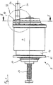
- the in Fig. 1 shown electric servomotor 2 is part of a steering gear of a submarine, with which an outside of the pressure hull of the submarine arranged rudder is provided.
- the rudder may be a rudder or a depth rudder of the submarine. Of the entire steering gear only the electric servomotor is shown.
- a motor housing of the servomotor 2 has a hollow cylindrical body 4.
- the main body 4 of the servo motor 2 which is a synchronous torque motor, a stator 6 and a hollow rotor 8 of the servo motor 2 are arranged.
- At the base 4 closes in Fig. 1 on the left side a flange 10 at.
- a flange 12 of the flange 10 the servo motor 2 is pressure-tightly attached to a pressure body bushing of the submarine.
- the outside of the spindle motor 2 part of the planetary roller spindle 16 is by the pressure body lead-through out of the pressure hull of the submarine and is there connected to a linkage, which in turn is coupled in motion with the rudder supplied by the rudder.
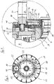
- a sleeve 18 is mounted and rotatably connected to the rotor 8.
- the sleeve 18 thus rotates with a rotation of the rotor 8 with the rotor 8.
- the sleeve 18 has a flange 20.
- the flange 20 is an annular collar extending radially outwardly from the outer surface of the sleeve 18.
- six holes 22 are uniformly distributed over the circumference. These holes 22 are provided for receiving screws, not shown, with which a gear ring 24 is fixed to the flange 20.
- a recess 26 For attachment to the flange 20 of the sleeve 18, the gear ring 24 on a front side, which faces away from the Plantenrollenspindeltrieb, a recess 26.
- the cross section in the recess 26 corresponds to the outer contour of the flange 20.
- the depth of the recess 26 is dimensioned so that a flat side facing away from the stator 6 of the flange 20 with the end face of the gear ring 24 is aligned.
- six holes 28 are also formed on the gear ring 24 for screwing the gear ring 24 with the flange 20.
- the gear ring 24 is provided on its outer periphery with a toothing, which is combed with a gear 30.
- the gear 30 is connected via a keyway-groove connection with a drive shaft 32 of an auxiliary drive 34.
- the auxiliary drive 34 is an air motor with a downstream planetary gear.
- the auxiliary drive 34 is not an integral part of the servo motor 2 and is coupled only in case of failure of the servo motor 2 with the gear 30.
- a subsequent to the drive shaft 32 section of a housing 36 of the auxiliary drive 34 passes through an opening 38 which is formed on a connecting part 40 which is arranged axially outside of the gear 30 on the side facing away from the planetary roller spindle end face of the motor housing of the servo motor 2.
- At the connection part 40 of the auxiliary drive 34 is fixed.
- the gear ring 24 is not fixedly connected by means of a screw connection with the flange 20 of the sleeve 18 fastened to the rotor 8.
- the flange 20 and the gear ring 24 in a contact region 42 in the formed on the gear ring 24 recess 26 form a releasable coupling.
- a dog toothing can be formed to form a dog clutch or a Hirth toothing.
- the auxiliary drive may be an integral part of the servomotor 2, that is permanently fixed to the connecting part 40, but in normal operation of the servo motor 2 no positive connection between the gear ring 24th and the flange 20 of the sleeve 18 and the rotor 8 should exist.
- a spring element not shown, arranged that biased is supported between the cover housing 46 and the gear ring 24 and the gear ring 24 is pushed away from the flange 20, so that no positive connection between the gear ring 24 and the flange 20 is made.
Description
- Unterseeboote sind bislang meist mit hydraulischen Rudermaschinen ausgerüstet. Diese Rudermaschinen werden von einer in dem Unterseeboot zentral angeordneten Hydraulikanlage mit Hydraulikflüssigkeit versorgt. Aus Sicherheitsgründen ist die Hydraulikanlage in der Regel mehrfach redundant aufgebaut. Sollte es dennoch zu einem Ausfall der Hydraulikanlage kommen, der die Versorgung der Rudermaschine mit Hydraulikflüssigkeit verhindert, steht üblicherweise zusätzlich eine druckluftbetriebene Hydraulikpumpe zur Verfügung, die die Versorgung der Rudermaschine mit der Hydraulikflüssigkeit dann gewährleistet. Selbst bei Versagen dieser druckluftbetriebenen Hydraulikpumpe kann der Rudermaschine die erforderliche Hydraulikflüssigkeit noch mit Handpumpen zugeführt werden.
- Eine Alternative zu den hydraulischen Rudermaschinen stellen Rudermaschinen mit einem elektrischen Stellmotor dar, wie er beispielsweise aus
DE 10 2010 015 665 A1 bekannt ist. Bei diesem Stellmotor ist dessen Ruder mit einem Spindeltrieb bewegungsgekoppelt, wobei der linear bewegliche Teil des Spindeltriebs, bei dem es sich wahlweise um die Spindel oder um die Spindelmutter handeln kann, über ein Gelenkgestänge auf das Ruder wirkt. Probleme ergeben sich allerdings bei einem Ausfall des Stellmotors, da dann eine Betätigung des Ruders nicht mehr möglich ist. DieDE 101 58 870 A1 beschreibt eine redundante, elektrische Antriebsvorrichtung zum Antrieb eines Schiffsruders.DE 20 2005 005 848 U1 offenbart ein Unterseeboot mit einem elektrischen Stellmotor, welcher mit dem Ruder bewegungsgekoppelt ist, und mit einem Hilfsantrieb. Vor diesem Hintergrund liegt der Erfindung die Aufgabe zugrunde, ein Unterseeboot, dessen Ruderanlage bzw. Ruderanlagen, die mit einem elektrischen Stellmotor ausgestattet sind, so zu verbessern, dass das bzw. die Ruder auch beim Ausfall des Stellmotors betätigt werden können. - Gelöst wird diese Aufgabe durch ein Unterseeboot mit den in Anspruch 1 angegebenen Merkmalen. Vorteilhafte Weiterbildungen dieses Unterseeboots ergeben sich aus den Unteransprüchen, der nachfolgenden Beschreibung sowie der Zeichnung. Hierbei können die in den Unteransprüchen angegebenen Merkmale jeweils für sich aber auch in geeigneter Kombination miteinander die erfindungsgemäße Lösung nach Anspruch 1 weiter ausgestalten.
- Das erfindungsgemäße Unterseeboot weist in üblicher Weise einen Druckkörper und mindestens eine Ruderanlage auf, die mindestens ein außerhalb des Druckkörpers angeordnetes Ruder, bei dem es sich um ein Seitenruder oder um ein Tiefenruder handeln kann und einen mit dem Ruder bewegungsgekoppelten Antrieb aufweist. Bei diesem Antrieb handelt es sich um einen elektrischen Stellmotor und vorzugsweise um einen Synchron-Torque-Motor, dessen Rotor mit einem drehbeweglichen Teil eines Spindeltriebs verbunden ist. Ein linearbeweglicher Teil des Spindeltriebs, bei dem es sich vorzugsweise um die Spindel handelt, ist durch eine Druckkörperdurchführung nach außerhalb des Druckkörpers geführt, wo dieser Teil des Spindeltriebs in bekannter Weise über ein Gelenkgestänge mit dem Ruderschaft des Ruders bewegungsgekoppelt ist.
- Um das Ruder auch bei einem Defekt des Stellmotors oder bei einem Ausfall der Spannungsversorgung des Stellmotors betätigen zu können, ist an dem Stellmotor ein Hilfsantrieb vorgesehen. Die Anordnung des Hilfsantriebs an den Stellmotor ist derart, dass ein von dem Hilfsantrieb erzeugtes Drehmoment unmittelbar oder mittelbar über ein Getriebe auf den Rotor des Stellmotors übertragen werden kann, so dass die Rudereinstellung über den Hilfsantrieb erfolgt. Dieser Hilfsantrieb kann vorteilhaft ein fester Bestandteil des Stellmotors sein, so dass der Stellmotor und der Hilfsantrieb eine gemeinsame Baueinheit bilden. Alternativ hierzu kann der Hilfsantrieb ein von dem Stellmotor separates Aggregat sein, welches nur bei Bedarf, d. h. bei einem Ausfall des Stellmotors an diesen angekoppelt wird, wobei der Stellmotor in letztgenanntem Fall eine hierfür geeignete Koppeleinrichtung aufweist.
- Als Hilfsantrieb können prinzipiell alle hierfür geeigneten Antriebsmotoren eingesetzt werden. So können z. B. elektrisch oder hydraulisch betätigte Motoren als Hilfsantrieb mit dem Rotor verbunden bzw. verbindbar sein. Daneben ist auch ein Handantrieb in Form eines mit dem Rotor verbundenen Handrads oder eine Kurbel als Hilfsantrieb denkbar. Bevorzugt ist als Hilfsantrieb aber ein Druckluftmotor vorgesehen. Dieser ist zweckmäßigerweise an dem in Unterseebooten üblicherweise vorhandenen Druckluftnetz angeschlossen. Vorteilhaft ist dem Druckluftmotor ein Planetengetriebe nachgeschaltet, um die vergleichsweisen hohen Betriebsdrehzahlen des Druckluftmotors herabzusetzen. Solche Druckluftmotoren mit einem nachgeschalteten Planetengetriebe sind am Markt als kompakte Baueinheit erhältlich.
- Zweckmäßigerweise ist die Verbindung des Hilfsantriebs mit dem Rotor des Stellmotors an einem von dem Antriebsende des Rotors abgewandten Ende des Rotors vorgesehen. Hierbei ist unter dem Antriebsende des Rotors das Ende des Rotors zu verstehen, an dem der Spindeltrieb mit dem Rotor verbunden ist. Die Verbindung des Hilfsantriebs erfolgt demnach vorzugsweise an einem von dem Spindeltrieb abgewandten Ende des Rotors, das zweckmäßigerweise aus dem Stator des Stellmotors herausragt. Erfindungsgemäß ist der Hilfsantrieb nicht direkt mit dem Rotor des Stellmotors verbunden bzw. verbindbar. Stattdessen ist zur Verbindung des Hilfsantriebs mit dem Rotor des Stellmotors ein Getriebe vorgesehen. Bei dem Getriebe kann es sich beispielsweise um ein Untersetzungsgetriebe handeln, mit dem die Drehzahl des Hilfsantriebs auf eine niedrigere Rotordrehzahl bei gleichzeitiger Erhöhung des auf den Rotor wirkenden Drehmoments herunter transformiert wird.
- Grundsätzlich können zur Drehmomentübertragung von dem Hilfsantrieb zu dem Rotor alle hierfür geeigneten Getriebe verwendet werden. Bevorzugt ist das Getriebe allerdings ein Zahnradgetriebe. Dieses ist vorzugsweise als ein Stirnradgetriebe ausgebildet, so dass eine Antriebswelle des Hilfsantriebs parallel zu dem Rotor des Stellmotors ausgerichtet ist. Insbesondere bei einer Ausgestaltung, bei der der Hilfsantrieb fester Bestandteil des Stellmotors ist, weist der Stellmotor erfindungsgemäß eine lösbare Kupplung auf, die zwischen einem mit dem Hilfsantrieb verbundenen Antriebsstrang des Getriebes und einem mit dem Rotor verbundenen Abtriebsstrang des Getriebes angeordnet ist. Diese Kupplung ist vorteilhaft dafür vorgesehen, die Verbindung des Hilfsantriebs mit dem Rotor des Stellmotors bei intaktem Stellmotor zu lösen und den Hilfsantrieb nur bei einem Ausfall des Stellmotors mit dem Rotor des Stellmotors zu verbinden.
- In vorteilhafter Weiterbildung dieser Ausgestaltung ist eine Hülse mit einem daran ausgebildeten Flansch, d. h. mit einem sich über den gesamten Umfang der Hülse erstreckenden radial auskragenden Kragen, drehfest mit dem Rotor verbunden. An einer Flachseite des Flansches ist mit dieser ein Zahnradring formschlüssig verbindbar. Hierbei kommt der Zahnradring, der vorzugsweise mit einer Außenverzahnung versehen ist, mit einer seiner Stirnseiten an der Flachseite des Flansches zur Anlage, wobei Formschlusselemente an den Zahnradring und an der Flachseite des Flansches die formschlüssige Verbindung von Zahnradring und Flansches schaffen. Der Zahnradring ist Teil eines Zahnradgetriebes, über das der Hilfsantrieb mit dem Rotor des Stellmotors verbindbar bzw. verbunden ist. Der Zahnradring und der Flansch der Hülse bilden hierbei eine lösbare Kupplung, bei der der Zahnradring zur Trennung der Verbindung zwischen dem Hilfsantrieb und dem Rotor von dem an der Hülse ausgebildeten Flansch wegbewegt wird. Umgekehrt wird zum Verbinden des Hilfsantriebs mit dem Rotor des Stellmotors der Flansch der Hülse zur Bildung eines Formschlusses zwischen den Zahnradring und der Erweiterung mit dem Zahnradring in Kontakt gebracht.
- Zur Bildung eines Formschlusses zwischen dem Zahnradring und dem Flansch können der Flansch und der Zahnradring vorteilhaft eine Klauenkupplung bilden. Demnach sind an dem Zahnradring und/oder dem Flansch an der Stirn- bzw. Flachseite vorstehende Klauen ausgebildet, die in Ausnehmungen an dem jeweils anderen Teil von Zahnradring und Flansch eingreifen oder einen dort ausgebildeten Vorsprung formschlüssig hintergreifen. Mit der so gebildeten Klauenkupplung lassen sich besonders gut Drehmomente von dem Hilfsantrieb auf die Hülse und damit einhergehend auf den Rotor des Stellmotors übertragen.
- Eine gleichermaßen gute Drehmomentübertragung ermöglicht auch eine Hirth-Verzahnung. So können der Flansch und der Zahnradring, anstatt eine Klauenkupplung zu bilden, vorteilhaft auch jeweils an einer Flachseite eine Hirth-Verzahnung aufweisen. Demzufolge ist stirnseitig des Zahnradrings und des Flansches jeweils eine Verzahnung ausgebildet, wobei die beiden Verzahnungen zur formschlüssigen Verbindung von Zahnradring und Flansch miteinander in Eingriff gebracht werden.
- Vorzugsweise ist vorgesehen, dass der Hilfsantrieb bei einem Normalbetrieb des Stellmotors nicht mit dessen Rotor verbunden ist, wobei der Zahnradring von dem Flansch getrennt ist, so dass kein Formschluss zwischen dem Zahnradring und dem Flansch besteht. Zu diesem Zweck weist der Stellmotor vorteilhafterweise ein Federelement auf, welches vorgespannt derart angeordnet ist, dass es die formschlüssige Verbindung von Hülse und Zahnradring trennt.
- Nachfolgend ist die Erfindung anhand eines in der Zeichnung dargestellten Ausführungsbeispiels näher erläutert. In der Zeichnung zeigt:
- Fig. 1
- in einer schematisch vereinfachten Seitenansicht einen Stellmotor einer Ruderanlage eines Unterseeboots mit einem daran angeordneten Hilfsantrieb,
- Fig. 2
- eine Schnittansicht entlang der Schnittlinie II - II in
Fig. 1 und - Fig. 3
- stark vergrößert eine Einzelheit III aus
Fig. 1 . - Der in
Fig. 1 dargestellte elektrische Stellmotor 2 ist Teil einer Ruderanlage eines Unterseeboots, mit der ein außerhalb des Druckkörpers des Unterseeboots angeordnetes Ruder gestellt wird. Bei dem Ruder kann es sich um ein Seitenruder oder um ein Tiefenruder des Unterseeboots handeln. Von der gesamten Ruderanlage ist nur der elektrische Stellmotor dargestellt. - Ein Motorgehäuse des Stellmotors 2 weist einen hohlzylindrischen Grundkörper 4 auf. In dem Grundkörper 4 des Stellmotors 2, bei dem es sich um einen Synchron-Torque-Motor handelt, sind ein Stator 6 und ein hohl ausgebildeter Rotor 8 des Stellmotors 2 angeordnet. An dem Grundkörper 4 schließt sich in
Fig. 1 linksseitig ein Flanschteil 10 an. Über einen Flansch 12 des Flanschteils 10 ist der Stellmotor 2 druckdicht an einer Druckkörperdurchführung des Unterseeboots befestigt. - An einer von dem Grundkörper 4 abgewandten Stirnseite des Flansches 12 ragt aus dem Flanschteil 10 eine mit dem Rotor 8 des Stellmotors 2 fest verbundene Spindelmutter 14 eines Plantenrollenspindeltriebs aus dem Motorgehäuse heraus. Durch die Spindelmutter 14, die bei Drehung des Rotors 8 des Stellmotors 2 die Drehbewegung des Rotors 8 ausführt, führt eine linearbewegbare Planetenrollenspindel 16 des Planetenrollenspindeltriebs in das Innere des Spindelmotors 2. Der außerhalb des Spindelmotors 2 befindliche Teil der Planetenrollenspindel 16 ist durch die Druckkörperdurchführung nach außerhalb des Druckkörpers des Unterseeboots geführt und ist dort mit einem Gelenkgestänge verbunden, welches wiederum mit dem von der Ruderanlage zustellenden Ruder bewegungsgekoppelt ist.
- Wie in
Fig. 3 dargestellt, ragt ein von dem Planetenrollenspindeltrieb abgewandtes Ende des Rotors 8 aus dem Stator 6 heraus. Auf dieses Ende des Rotors 8 ist eine Hülse 18 aufgesetzt und drehfest mit dem Rotor 8 verbunden. Die Hülse 18 dreht somit bei einer Drehung des Rotors 8 mit dem Rotor 8 mit. An ihrem dem Stator 6 zugewandten Ende weist die Hülse 18 einen Flansch 20 auf. Bei dem Flansch 20 handelt es sich um einen ringförmigen Kragen, der sich ausgehend von der äußeren Mantelfläche der Hülse 18 radial nach Außen erstreckt. An dem Flansch 20 sind gleichmäßig über deren Umfang verteilt sechs Bohrungen 22 ausgebildet. Diese Bohrungen 22 sind zur Aufnahme von nicht dargestellten Schrauben vorgesehen, mit denen ein Zahnradring 24 an dem Flansch 20 befestigt ist. - Zur Befestigung an dem Flansch 20 der Hülse 18 weist der Zahnradring 24 an einer Stirnseite, die von dem Plantenrollenspindeltrieb abgewandt ist, eine Ausnehmung 26 auf. Der Querschnitt in der Ausnehmung 26 korrespondiert mit der Außenkontur des Flansches 20. Die Tiefe der Ausnehmung 26 ist so bemessen, dass eine von dem Stator 6 abgewandte Flachseite des Flansches 20 mit der Stirnseite des Zahnradrings 24 fluchtet. Korrespondierend zur Lage der an dem Flansch 20 ausgebildeten Bohrungen 22 sind auch an dem Zahnradring 24 sechs Bohrungen 28 zur Verschraubung des Zahnradrings 24 mit dem Flansch 20 ausgebildet.
- Der Zahnradring 24 ist an seinem Außenumfang mit einer Verzahnung versehen, die mit einem Zahnrad 30 gekämmt wird. Das Zahnrad 30 ist über eine Passfeder-Nut-Verbindung mit einer Antriebswelle 32 eines Hilfsantriebs 34 verbunden. Bei dem Hilfsantrieb 34 handelt es sich um einen Druckluftmotor mit einem nachgeschalteten Planetengetriebe.
- Der Hilfsantrieb 34 ist nicht fester Bestandteil des Stellmotors 2 und wird nur bei einem Ausfall des Stellmotors 2 mit dem Zahnrad 30 gekoppelt. In diesem Fall durchgreift ein an die Antriebswelle 32 anschließender Abschnitt eines Gehäuses 36 des Hilfsantriebs 34 eine Durchbrechung 38, die an einem Anschlussteil 40 ausgebildet ist, welches axial außenseitig des Zahnrads 30 an der von dem Planetenrollenspindeltrieb abgewandten Stirnseite des Motorgehäuses des Stellmotors 2 angeordnet ist. An dem Anschlussteil 40 ist der Hilfsantrieb 34 festgelegt.
- Alternativ zu der in der Zeichnung dargestellten Ausgestaltung ist der Zahnradring 24 nicht mittels einer Schraubverbindung mit dem Flansch 20 der an dem Rotor 8 befestigten Hülse 18 fest verbunden. Stattdessen bilden der Flansch 20 und der Zahnradring 24 in einem Kontaktbereich 42 in der an dem Zahnradring 24 ausgebildeten Ausnehmung 26 eine lösbare Kupplung. Hierzu kann an der Bodenfläche der Ausnehmung 26 und an dem diese Bodenfläche kontaktierenden Bereich des Flansches 20 eine Klauenverzahnung zur Bildung einer Klauenkupplung oder eine Hirth-Verzahnung ausgebildet sein. In diesem Fall kann der Hilfsantrieb fester Bestandteil des Stellmotors 2 sein, also dauerhaft an dem Anschlussteil 40 festgelegt sein, wobei aber bei Normalbetrieb des Stellmotors 2 keine formschlüssige Verbindung zwischen dem Zahnradring 24 und dem Flansch 20 der Hülse 18 bzw. dem Rotor 8 bestehen soll. Zu diesem Zweck ist in einem Raum 44, der an der von dem Planentenrollenspindeltrieb abgewandten Seite des Flansches 20 und des Zahnradrings 24 ausgebildet ist, und außenseitig von einer die Hülse 18 radial umgebenden Abdeckgehäuse 46 begrenzt wird, ein nicht dargestelltes Federelement angeordnet, dass sich vorgespannt zwischen dem Abdeckgehäuse 46 und dem Zahnradring 24 abstützt und den Zahnradring 24 von dem Flansch 20 wegdrückt, so dass keine formschlüssige Verbindung zwischen dem Zahnradring 24 und dem Flansch 20 besteht. Bei einem Ausfall des Stellmotors 2 wird mit dem Druckluftmotor des Hilfsantriebs 34 Druckluft in einen freien Raum 48 geleitet, der an der dem Planetenrollenspindeltriebs zugewandten Seite des Zahnrads 30 und des Zahnradrings 24 ausgebildet ist und hierdurch der Zahnradring 24 gegen die Federkraft des in dem Raum 44 angeordneten Federelements in Richtung des Flansches 20 gedrückt, wo sich der Zahnradring 24 formschlüssig mit dem Flansch 20 verbindet, so dass nun eine Bewegungskopplung des Hilfsantriebs 34 mit dem Rotor 8 des Stellmotors 2 besteht.
-
- 2
- - Stellmotor
- 4
- - Grundkörper
- 6
- - Stator
- 8
- - Rotor
- 10
- - Flanschteil
- 12
- - Flansch
- 14
- - Spindelmutter
- 16
- - Planetenrollenspindel
- 18
- - Hülse
- 20
- - Flansch
- 22
- - Bohrung
- 24
- - Zahnradring
- 26
- - Ausnehmung
- 28
- - Bohrung
- 30
- - Zahnrad
- 32
- - Antriebswelle
- 34
- - Hilfsantrieb
- 36
- - Gehäuse
- 38
- - Durchbrechung
- 40
- - Anschlussteil
- 42
- - Kontaktbereich
- 44
- - Raum
- 46
- - Abdeckgehäuse
- 48
- - Raum
Claims (9)
- Unterseeboot mit einem Druckkörper, mit mindestens einem außerhalb des Druckkörpers angeordneten Ruder und mit einem in dem Druckkörper angeordneten elektrischen Stellmotor (2), welcher mit dem Ruder bewegungsgekoppelt ist und an welchem ein Hilfsantrieb (34) vorgesehen ist dadurch gekennzeichnet, dass zur Verbindung des Hilfsantriebs (34) mit dem Rotor (8) des Stellmotor (2) ein Getriebe vorgesehen ist, und dass der Stellmotor (2) eine lösbare Kupplung aufweist, die zwischen einem mit dem Hilfsantrieb (34) verbundenen Antriebsstrang des Getriebes und einem mit dem Rotor (8) verbundenen Abtriebsstrang des Getriebes anneordnet ist
- Unterseeboot nach Anspruch 1, dadurch gekennzeichnet, dass eine Verbindung des Hilfsantriebs (34) mit einem Rotor (8) des Stellmotors (2) an einem von dem Antriebsende des Rotors (8) abgewandten Ende des Rotors (8) vorgesehen ist.
- Unterseeboot nach Anspruch 2, dadurch gekennzeichnet, dass das Getriebe ein Zahnradaetriebe ist.
- Unterseeboot nach einem der vorangehenden Ansprüche, dadurch gekennzeichnet, dass der Hilfsantrieb (34) fester Bestandteil des Stellmotors (2) ist.
- Unterseeboot nach einem der vorangehenden Ansprüche, dadurch gekennzeichnet, dass der Hilfsantrieb (34) einen Druckluftmotor aufweist.
- Unterseeboot nach einem der vorangehenden Ansprüche, dadurch gekennzeichnet, dass mit dem Rotor (8) eine Hülse (18) drehfest verbunden ist, welche einen Flansch (20) aufweist, wobei ein Zahnradring (24) an einer Flachseite des Flansches (20) formschlüssig mit der Hülse (18) kupplungsverhindbar ist
- Unterseeboot nach Anspruch 6, dadurch gekennzeichnet, dass der Flansch (20) und der Zahnradring (24) eine Klauenkiupplung hilden.
- Unterseeboot nach Anspruch 6, dadurch gekennzeichnet, dass der Flansch (20) und der Zahnradring (24) jeweils an einer Flanhseite eine Hirth-Verzahnung aufweist.
- Unterseeboot nach einem der Ansprüche 6 bis 8, dadurch gekennzeichnet, dass der Stellmotor (2) ein Federelement aufweist, welches vorgespannt derart angeordnet ist, dass es die formschlüssige Verbindung von Hülse (18) und Zahnradring (24) trennt.
Applications Claiming Priority (2)
| Application Number | Priority Date | Filing Date | Title |
|---|---|---|---|
| DE102012220918.2A DE102012220918B3 (de) | 2012-11-15 | 2012-11-15 | Unterseeboot |
| PCT/EP2013/073469 WO2014076025A1 (de) | 2012-11-15 | 2013-11-11 | Unterseeboot |
Publications (2)
| Publication Number | Publication Date |
|---|---|
| EP2920063A1 EP2920063A1 (de) | 2015-09-23 |
| EP2920063B1 true EP2920063B1 (de) | 2018-08-08 |
Family
ID=49578288
Family Applications (1)
| Application Number | Title | Priority Date | Filing Date |
|---|---|---|---|
| EP13789543.9A Active EP2920063B1 (de) | 2012-11-15 | 2013-11-11 | Unterseeboot |
Country Status (7)
| Country | Link |
|---|---|
| EP (1) | EP2920063B1 (de) |
| KR (1) | KR101954488B1 (de) |
| AU (1) | AU2013346967B2 (de) |
| DE (1) | DE102012220918B3 (de) |
| ES (1) | ES2688524T3 (de) |
| TR (1) | TR201816337T4 (de) |
| WO (1) | WO2014076025A1 (de) |
Families Citing this family (1)
| Publication number | Priority date | Publication date | Assignee | Title |
|---|---|---|---|---|
| KR20190072371A (ko) | 2017-12-15 | 2019-06-25 | 대우조선해양 주식회사 | 잠수함 추진장치 |
Family Cites Families (10)
| Publication number | Priority date | Publication date | Assignee | Title |
|---|---|---|---|---|
| GB191210241A (en) * | 1912-04-30 | 1912-09-05 | Vittorio Locarni | Steering Gear, particularly for Submarine Boats. |
| GB191327471A (en) * | 1912-11-30 | 1915-01-07 | Anonima Italiana Gio Ansaldo & | Improvements in Motion Transmission Mechanism applicable to the Steering of Ships. |
| US1213153A (en) * | 1913-12-19 | 1917-01-23 | Engrenages Citroen Sa Des | Submarine steering apparatus. |
| DE449909C (de) * | 1925-03-17 | 1927-09-23 | Sterry Baines Freeman | Schiffssteuerungsgetriebe |
| GB2348630B (en) * | 1998-09-09 | 2002-12-04 | Luk Lamellen & Kupplungsbau | Drive train |
| DE10158870A1 (de) * | 2001-11-14 | 2003-05-22 | Bosch Rexroth Ag | Redundante elektrische Antriebsvorrichtung, insbesondere zum Antrieb eines Ruders an einem Schiff |
| DE202005005848U1 (de) * | 2005-04-12 | 2006-08-17 | Moog Gmbh | Rudermaschinenantrieb für ein Schiff |
| KR101115124B1 (ko) * | 2009-07-09 | 2012-02-24 | 대우조선해양 주식회사 | 출몰식 방향타를 가지는 무인잠수정 |
| DE102010015665A1 (de) * | 2010-04-16 | 2011-10-20 | Esw Gmbh | Linearantrieb für eine Schiffsrudermaschine |
| KR101177680B1 (ko) * | 2012-01-09 | 2012-08-27 | 김현호 | 안전성이 강화된 전동 꺼꾸리 운동장치 |
-
2012
- 2012-11-15 DE DE102012220918.2A patent/DE102012220918B3/de not_active Expired - Fee Related
-
2013
- 2013-11-11 AU AU2013346967A patent/AU2013346967B2/en active Active
- 2013-11-11 EP EP13789543.9A patent/EP2920063B1/de active Active
- 2013-11-11 WO PCT/EP2013/073469 patent/WO2014076025A1/de active Application Filing
- 2013-11-11 KR KR1020157015683A patent/KR101954488B1/ko active IP Right Grant
- 2013-11-11 ES ES13789543.9T patent/ES2688524T3/es active Active
- 2013-11-11 TR TR2018/16337T patent/TR201816337T4/tr unknown
Non-Patent Citations (1)
| Title |
|---|
| None * |
Also Published As
| Publication number | Publication date |
|---|---|
| KR20150085021A (ko) | 2015-07-22 |
| AU2013346967A1 (en) | 2015-05-28 |
| AU2013346967B2 (en) | 2017-06-22 |
| DE102012220918B3 (de) | 2014-03-13 |
| EP2920063A1 (de) | 2015-09-23 |
| TR201816337T4 (tr) | 2018-11-21 |
| ES2688524T3 (es) | 2018-11-05 |
| WO2014076025A1 (de) | 2014-05-22 |
| KR101954488B1 (ko) | 2019-03-05 |
Similar Documents
| Publication | Publication Date | Title |
|---|---|---|
| EP3189237B1 (de) | Exzenterschneckenpumpe | |
| EP3548349B1 (de) | Elektrohydraulischer fremdkraft-druckerzeuger | |
| EP3077706B1 (de) | Linearaktuator | |
| EP2384839B1 (de) | Spanneinrichtung | |
| EP1637260B1 (de) | Spanneinrichtung für Werkzeugmaschinen | |
| DE102014009833B4 (de) | Antriebseinheit für ein elektrisch unterstütztes Fahrrad. | |
| DE102016011361B4 (de) | Elektronische scheibenbremse | |
| DE102016011359B4 (de) | Elektronische scheibenbremse | |
| WO2020089208A1 (de) | Kugelumlauflenkung | |
| EP2041430B1 (de) | Bremsvorrichtung | |
| DE102010032902A1 (de) | Elektromechanischer Bremskraftverstärker und Bremssystem | |
| EP3191293B1 (de) | Antrieb einer maschine, drehmomentmotor, kupplungseinrichtung, vorrichtung zum bearbeiten von werkstoffen und verwendung eines torquemotors | |
| EP2920063B1 (de) | Unterseeboot | |
| WO2008138505A1 (de) | Motorbetriebene arbeits-spindel für eine werkzeug-maschine | |
| EP2398698B1 (de) | Bootsantrieb mit steuereinrichtung | |
| DE102015211477B4 (de) | Hydrostatischer Kupplungsaktor | |
| DE102007057391A1 (de) | Zahnstangen-Hilfskraftlenkung | |
| DE102013210793B4 (de) | Unterseeboot | |
| WO2014187664A1 (de) | Lenkgetriebe mit hydraulischer unterstützung mittels eines drehkolbens | |
| DE102014219361B4 (de) | Kupplungsbetätigungssystem | |
| DE102012220920B3 (de) | Unterseeboot | |
| DE102015217050A1 (de) | Nutzfahrzeuglenkung | |
| DE102007053694B4 (de) | Fahrzeug-Lenksystem | |
| DE102020114804B4 (de) | Lenksystem für einen Außenbordmotor | |
| DE102014108948B3 (de) | Servolenkbaugruppe mit Lenkmomentüberlagerung |
Legal Events
| Date | Code | Title | Description |
|---|---|---|---|
| PUAI | Public reference made under article 153(3) epc to a published international application that has entered the european phase |
Free format text: ORIGINAL CODE: 0009012 |
|
| 17P | Request for examination filed |
Effective date: 20150416 |
|
| AK | Designated contracting states |
Kind code of ref document: A1 Designated state(s): AL AT BE BG CH CY CZ DE DK EE ES FI FR GB GR HR HU IE IS IT LI LT LU LV MC MK MT NL NO PL PT RO RS SE SI SK SM TR |
|
| AX | Request for extension of the european patent |
Extension state: BA ME |
|
| DAX | Request for extension of the european patent (deleted) | ||
| RIC1 | Information provided on ipc code assigned before grant |
Ipc: B63H 25/26 20060101AFI20180301BHEP Ipc: B63G 8/18 20060101ALI20180301BHEP Ipc: H02K 7/00 20060101ALI20180301BHEP Ipc: H02K 7/10 20060101ALI20180301BHEP |
|
| GRAP | Despatch of communication of intention to grant a patent |
Free format text: ORIGINAL CODE: EPIDOSNIGR1 |
|
| INTG | Intention to grant announced |
Effective date: 20180409 |
|
| GRAS | Grant fee paid |
Free format text: ORIGINAL CODE: EPIDOSNIGR3 |
|
| GRAA | (expected) grant |
Free format text: ORIGINAL CODE: 0009210 |
|
| AK | Designated contracting states |
Kind code of ref document: B1 Designated state(s): AL AT BE BG CH CY CZ DE DK EE ES FI FR GB GR HR HU IE IS IT LI LT LU LV MC MK MT NL NO PL PT RO RS SE SI SK SM TR |
|
| REG | Reference to a national code |
Ref country code: GB Ref legal event code: FG4D Free format text: NOT ENGLISH |
|
| REG | Reference to a national code |
Ref country code: CH Ref legal event code: EP Ref country code: AT Ref legal event code: REF Ref document number: 1026671 Country of ref document: AT Kind code of ref document: T Effective date: 20180815 |
|
| REG | Reference to a national code |
Ref country code: IE Ref legal event code: FG4D Free format text: LANGUAGE OF EP DOCUMENT: GERMAN |
|
| REG | Reference to a national code |
Ref country code: DE Ref legal event code: R096 Ref document number: 502013010819 Country of ref document: DE |
|
| REG | Reference to a national code |
Ref country code: ES Ref legal event code: FG2A Ref document number: 2688524 Country of ref document: ES Kind code of ref document: T3 Effective date: 20181105 |
|
| REG | Reference to a national code |
Ref country code: SE Ref legal event code: TRGR |
|
| REG | Reference to a national code |
Ref country code: NL Ref legal event code: MP Effective date: 20180808 Ref country code: DE Ref legal event code: R084 Ref document number: 502013010819 Country of ref document: DE |
|
| REG | Reference to a national code |
Ref country code: LT Ref legal event code: MG4D |
|
| PG25 | Lapsed in a contracting state [announced via postgrant information from national office to epo] |
Ref country code: PL Free format text: LAPSE BECAUSE OF FAILURE TO SUBMIT A TRANSLATION OF THE DESCRIPTION OR TO PAY THE FEE WITHIN THE PRESCRIBED TIME-LIMIT Effective date: 20180808 Ref country code: RS Free format text: LAPSE BECAUSE OF FAILURE TO SUBMIT A TRANSLATION OF THE DESCRIPTION OR TO PAY THE FEE WITHIN THE PRESCRIBED TIME-LIMIT Effective date: 20180808 Ref country code: LT Free format text: LAPSE BECAUSE OF FAILURE TO SUBMIT A TRANSLATION OF THE DESCRIPTION OR TO PAY THE FEE WITHIN THE PRESCRIBED TIME-LIMIT Effective date: 20180808 Ref country code: NL Free format text: LAPSE BECAUSE OF FAILURE TO SUBMIT A TRANSLATION OF THE DESCRIPTION OR TO PAY THE FEE WITHIN THE PRESCRIBED TIME-LIMIT Effective date: 20180808 Ref country code: BG Free format text: LAPSE BECAUSE OF FAILURE TO SUBMIT A TRANSLATION OF THE DESCRIPTION OR TO PAY THE FEE WITHIN THE PRESCRIBED TIME-LIMIT Effective date: 20181108 Ref country code: GR Free format text: LAPSE BECAUSE OF FAILURE TO SUBMIT A TRANSLATION OF THE DESCRIPTION OR TO PAY THE FEE WITHIN THE PRESCRIBED TIME-LIMIT Effective date: 20181109 Ref country code: FI Free format text: LAPSE BECAUSE OF FAILURE TO SUBMIT A TRANSLATION OF THE DESCRIPTION OR TO PAY THE FEE WITHIN THE PRESCRIBED TIME-LIMIT Effective date: 20180808 Ref country code: IS Free format text: LAPSE BECAUSE OF FAILURE TO SUBMIT A TRANSLATION OF THE DESCRIPTION OR TO PAY THE FEE WITHIN THE PRESCRIBED TIME-LIMIT Effective date: 20181208 Ref country code: NO Free format text: LAPSE BECAUSE OF FAILURE TO SUBMIT A TRANSLATION OF THE DESCRIPTION OR TO PAY THE FEE WITHIN THE PRESCRIBED TIME-LIMIT Effective date: 20181108 |
|
| PG25 | Lapsed in a contracting state [announced via postgrant information from national office to epo] |
Ref country code: HR Free format text: LAPSE BECAUSE OF FAILURE TO SUBMIT A TRANSLATION OF THE DESCRIPTION OR TO PAY THE FEE WITHIN THE PRESCRIBED TIME-LIMIT Effective date: 20180808 Ref country code: LV Free format text: LAPSE BECAUSE OF FAILURE TO SUBMIT A TRANSLATION OF THE DESCRIPTION OR TO PAY THE FEE WITHIN THE PRESCRIBED TIME-LIMIT Effective date: 20180808 Ref country code: AL Free format text: LAPSE BECAUSE OF FAILURE TO SUBMIT A TRANSLATION OF THE DESCRIPTION OR TO PAY THE FEE WITHIN THE PRESCRIBED TIME-LIMIT Effective date: 20180808 |
|
| PG25 | Lapsed in a contracting state [announced via postgrant information from national office to epo] |
Ref country code: RO Free format text: LAPSE BECAUSE OF FAILURE TO SUBMIT A TRANSLATION OF THE DESCRIPTION OR TO PAY THE FEE WITHIN THE PRESCRIBED TIME-LIMIT Effective date: 20180808 Ref country code: CZ Free format text: LAPSE BECAUSE OF FAILURE TO SUBMIT A TRANSLATION OF THE DESCRIPTION OR TO PAY THE FEE WITHIN THE PRESCRIBED TIME-LIMIT Effective date: 20180808 Ref country code: EE Free format text: LAPSE BECAUSE OF FAILURE TO SUBMIT A TRANSLATION OF THE DESCRIPTION OR TO PAY THE FEE WITHIN THE PRESCRIBED TIME-LIMIT Effective date: 20180808 |
|
| REG | Reference to a national code |
Ref country code: DE Ref legal event code: R097 Ref document number: 502013010819 Country of ref document: DE |
|
| PG25 | Lapsed in a contracting state [announced via postgrant information from national office to epo] |
Ref country code: SK Free format text: LAPSE BECAUSE OF FAILURE TO SUBMIT A TRANSLATION OF THE DESCRIPTION OR TO PAY THE FEE WITHIN THE PRESCRIBED TIME-LIMIT Effective date: 20180808 Ref country code: DK Free format text: LAPSE BECAUSE OF FAILURE TO SUBMIT A TRANSLATION OF THE DESCRIPTION OR TO PAY THE FEE WITHIN THE PRESCRIBED TIME-LIMIT Effective date: 20180808 Ref country code: SM Free format text: LAPSE BECAUSE OF FAILURE TO SUBMIT A TRANSLATION OF THE DESCRIPTION OR TO PAY THE FEE WITHIN THE PRESCRIBED TIME-LIMIT Effective date: 20180808 |
|
| PLBE | No opposition filed within time limit |
Free format text: ORIGINAL CODE: 0009261 |
|
| STAA | Information on the status of an ep patent application or granted ep patent |
Free format text: STATUS: NO OPPOSITION FILED WITHIN TIME LIMIT |
|
| REG | Reference to a national code |
Ref country code: CH Ref legal event code: PL |
|
| 26N | No opposition filed |
Effective date: 20190509 |
|
| PG25 | Lapsed in a contracting state [announced via postgrant information from national office to epo] |
Ref country code: LU Free format text: LAPSE BECAUSE OF NON-PAYMENT OF DUE FEES Effective date: 20181111 Ref country code: MC Free format text: LAPSE BECAUSE OF FAILURE TO SUBMIT A TRANSLATION OF THE DESCRIPTION OR TO PAY THE FEE WITHIN THE PRESCRIBED TIME-LIMIT Effective date: 20180808 |
|
| REG | Reference to a national code |
Ref country code: BE Ref legal event code: MM Effective date: 20181130 |
|
| REG | Reference to a national code |
Ref country code: IE Ref legal event code: MM4A |
|
| PG25 | Lapsed in a contracting state [announced via postgrant information from national office to epo] |
Ref country code: SI Free format text: LAPSE BECAUSE OF FAILURE TO SUBMIT A TRANSLATION OF THE DESCRIPTION OR TO PAY THE FEE WITHIN THE PRESCRIBED TIME-LIMIT Effective date: 20180808 Ref country code: LI Free format text: LAPSE BECAUSE OF NON-PAYMENT OF DUE FEES Effective date: 20181130 Ref country code: CH Free format text: LAPSE BECAUSE OF NON-PAYMENT OF DUE FEES Effective date: 20181130 |
|
| REG | Reference to a national code |
Ref country code: DE Ref legal event code: R081 Ref document number: 502013010819 Country of ref document: DE Owner name: THYSSENKRUPP MARINE SYSTEMS GMBH, DE Free format text: FORMER OWNER: THYSSENKRUPP MARINE SYSTEMS GMBH, 24143 KIEL, DE |
|
| PG25 | Lapsed in a contracting state [announced via postgrant information from national office to epo] |
Ref country code: IE Free format text: LAPSE BECAUSE OF NON-PAYMENT OF DUE FEES Effective date: 20181111 |
|
| PG25 | Lapsed in a contracting state [announced via postgrant information from national office to epo] |
Ref country code: BE Free format text: LAPSE BECAUSE OF NON-PAYMENT OF DUE FEES Effective date: 20181130 |
|
| REG | Reference to a national code |
Ref country code: AT Ref legal event code: MM01 Ref document number: 1026671 Country of ref document: AT Kind code of ref document: T Effective date: 20181111 |
|
| PG25 | Lapsed in a contracting state [announced via postgrant information from national office to epo] |
Ref country code: AT Free format text: LAPSE BECAUSE OF NON-PAYMENT OF DUE FEES Effective date: 20181111 Ref country code: MT Free format text: LAPSE BECAUSE OF FAILURE TO SUBMIT A TRANSLATION OF THE DESCRIPTION OR TO PAY THE FEE WITHIN THE PRESCRIBED TIME-LIMIT Effective date: 20180808 |
|
| PG25 | Lapsed in a contracting state [announced via postgrant information from national office to epo] |
Ref country code: PT Free format text: LAPSE BECAUSE OF FAILURE TO SUBMIT A TRANSLATION OF THE DESCRIPTION OR TO PAY THE FEE WITHIN THE PRESCRIBED TIME-LIMIT Effective date: 20180808 |
|
| PG25 | Lapsed in a contracting state [announced via postgrant information from national office to epo] |
Ref country code: HU Free format text: LAPSE BECAUSE OF FAILURE TO SUBMIT A TRANSLATION OF THE DESCRIPTION OR TO PAY THE FEE WITHIN THE PRESCRIBED TIME-LIMIT; INVALID AB INITIO Effective date: 20131111 Ref country code: MK Free format text: LAPSE BECAUSE OF NON-PAYMENT OF DUE FEES Effective date: 20180808 Ref country code: CY Free format text: LAPSE BECAUSE OF FAILURE TO SUBMIT A TRANSLATION OF THE DESCRIPTION OR TO PAY THE FEE WITHIN THE PRESCRIBED TIME-LIMIT Effective date: 20180808 |
|
| PGFP | Annual fee paid to national office [announced via postgrant information from national office to epo] |
Ref country code: ES Payment date: 20230125 Year of fee payment: 10 |
|
| PGFP | Annual fee paid to national office [announced via postgrant information from national office to epo] |
Ref country code: GB Payment date: 20231123 Year of fee payment: 11 |
|
| PGFP | Annual fee paid to national office [announced via postgrant information from national office to epo] |
Ref country code: TR Payment date: 20231110 Year of fee payment: 11 Ref country code: SE Payment date: 20231120 Year of fee payment: 11 Ref country code: IT Payment date: 20231124 Year of fee payment: 11 Ref country code: FR Payment date: 20231120 Year of fee payment: 11 Ref country code: DE Payment date: 20231121 Year of fee payment: 11 |
|
| PGFP | Annual fee paid to national office [announced via postgrant information from national office to epo] |
Ref country code: ES Payment date: 20240129 Year of fee payment: 11 |