EP2920053B1 - A fin plug for a water craft - Google Patents
A fin plug for a water craft Download PDFInfo
- Publication number
- EP2920053B1 EP2920053B1 EP13855957.0A EP13855957A EP2920053B1 EP 2920053 B1 EP2920053 B1 EP 2920053B1 EP 13855957 A EP13855957 A EP 13855957A EP 2920053 B1 EP2920053 B1 EP 2920053B1
- Authority
- EP
- European Patent Office
- Prior art keywords
- fin
- fin plug
- plug
- foam
- top surface
- Prior art date
- Legal status (The legal status is an assumption and is not a legal conclusion. Google has not performed a legal analysis and makes no representation as to the accuracy of the status listed.)
- Active
Links
Images












Classifications
-
- B—PERFORMING OPERATIONS; TRANSPORTING
- B63—SHIPS OR OTHER WATERBORNE VESSELS; RELATED EQUIPMENT
- B63B—SHIPS OR OTHER WATERBORNE VESSELS; EQUIPMENT FOR SHIPPING
- B63B32/00—Water sports boards; Accessories therefor
- B63B32/60—Board appendages, e.g. fins, hydrofoils or centre boards
- B63B32/66—Arrangements for fixation to the board, e.g. fin boxes or foil boxes
Definitions
- the present invention relates to a fin plug, for installation in a water craft, such as a surfboard or the like, adapted to enable a fin to be removably attached to the water craft.
- a water craft such as a surf-craft, particularly one on which a person stands, kneels or sits, when traversing water or riding a wave, generally has at least one fin in an underside of the craft, generally near the tail end of the craft.
- Such fins have a number of functions, including: enabling the craft to travel in a desired direction; facilitating the turning of the craft; preventing the craft from slipping sideways; and providing greater control over the movement of the craft, such as when riding a wave.
- Some surf craft have the fins integrally formed on the surf craft and, for many years, this was the standard means for incorporating fins into such surfcraft. In the last twenty years or so, it has become more common for surfcraft to incorporate a removable fin or, more commonly, fin systems which include a number of removable fins. Such fin systems have numerous benefits, including enabling the fins to be removed for transportation and travelling, allowing damaged fins to be easily replaced and enabling fins of different shapes or styles to be selectively used.
- Such fin systems typically include at least one fin plug embedded into the underside of the surfcraft. This fin plug generally has at least one cavity adapted to receive a base portion (or a base element) of a surfcraft fin. The surfcraft fin is attached to the surfcraft by securing the base portion (or base element) of the fin into the cavity (or cavities) of the fin plug.
- There are numerous known fin systems which adopt this general arrangement.
- fins having 2 projecting base elements (or tabs) and, for each fin, two fin plugs installed in the underside of the surfcraft.
- Each of the fin plugs has a cavity for receiving one of the base elements.
- Each fin plug also includes means for securing the base element into the cavity.
- fin systems comprise a single fin plug, with a single cavity, for each fin.
- a fin system has quite a large fin plug with an elongated fin cavity for receiving the base element of the fin.
- the fin plug of such systems also typically includes an upper flat portion having an opening from which the fin cavity extends inwardly and a flange section extending laterally about the opening. This flange section has a particular width. Extending downwardly from an underside of the flat upper portion is a body portion which surrounds the fin cavity.
- the shape of such a fin plug generally requires two cavities to be routed into the underside of the surfcraft in a two-step process.
- a relatively wide, shallow cavity needs to be formed, the dimensions of which substantially correspond to the shape of the flange section.
- the depth of this first cavity will substantially correspond with the width of the flange section.
- a narrow, deeper cavity needs to be formed in the first mentioned cavity, which is adapted to receive the body portion of the fin plug.
- fin plugs Another problem with known fin plugs is that the bond formed between the fin plug and the resinous material with which the fin plug is typically secured within a surfboard blank can be, or can become, flawed, particularly as a result of pressure placed upon the surfcraft fin (which, in use, is connected to the fin plug).
- the means by which a fin plug is secured within a surfcraft is typically by means of a harden-able liquid resinous material between external surfaces of the fin plug and the wall(s) of the cavity into which the fin plug is inserted.
- each of the fin plugs has a top surface (being the surface on which the opening to the cavity is located) and following installation in the surfcraft, this top surface is exposed, being flush with the surface of the underside of the surfcraft.
- each fin plug has a top surface (again being the surface on which the opening to each cavity is located). Following installation in the surfcraft, this top surface is not exposed but, rather, sits under a fibreglass layer. This fiberglass layer above the fin plug top surface is generally continuous with the fibreglass layer of the underside of the surfcraft. The fiberglass layer which sits over the top surface of the fin plug enhances the secure fixation of the fin plug to the surfcraft.
- a further problem with most known fin plugs is that, when installed in a surfcraft, they are surrounded by the relatively low density foam of which the surfcraft is formed.
- foam may not generally provide sufficient strength to support the loads placed upon the fin plug, due to forces applied to the attached fin, without some deformation, weakening or crushing of the surrounding foam over time.
- Such deformation or weakening of the foam may cause the fin plug to sink into the foam or to shift out of alignment, with consequential reduction in performance of the attached fin. This can also cause the fibreglass skin, in the vicinity of the fin plug, to crack or shatter.
- the fin plug sinks into the foam body, it can cause the top surface of the fin plug to separate from the adjoining fiberglass layer.
- Surfcraft fins can be subject to very substantial forces (especially lateral forces) when the surfcraft is undergoing a turn or upon impact with some other object and these forces are then transferred to the corresponding fin plugs to which the fins are attached. These forces can place very substantial strains on the connections (formed of hardened resinous material) between the fin plug and the surfcraft. In turn, these connections can be weakened and, in some cases, the hardened resinous material can crack). These strains upon the abovementioned connections are generally in inverse proportion to the total area of the external surfaces of the fin plug. Accordingly, the smaller this area, the greater will be the strain placed upon the relevant connection.
- the present invention is directed towards ameliorating at least some of the above described problems associated with prior art fin plugs and, consequently, the methods of installing these.
- one object of the present invention is directed towards providing a fin plug assembly which is adapted to form a stronger bond with the resinous material with which it is secured to a surfcraft.
- a composite fin plug mounting for a fin including:
- the fin plug includes a plurality of said holes extending between the top surface and the bottom surface. It is further preferred that the fin plug includes a planar portion, having said top surface and bottom surface, and a base portion extending from said bottom surface and surrounding said at least one fin cavity.
- the planar portion of the fin plug preferably includes a flange extending laterally from said a least one opening to an external perimeter.
- the fin plug includes two fin cavities for receiving two base elements of a water craft fin, said fin cavities extending inwardly from two openings in the top surface of said planar portion.
- the holes extend through the flange of the planar portion.
- a composite fin plug mounting as previously described wherein the fin plug has a honeycomb-like structure and comprises a plurality of apertures extending from the top surface to a base surface of a base portion of the fin plug, the base portion substantially including the at least one fin cavity, wherein the foam material is located in at least some of the plurality of apertures.
- the holes Preferably, the holes have a length of up to about 2 cm.
- the holes are located in the planar portion of the fin plug and, in this embodiment; the holes have a length of up to about 0.5 cm. Preferably, the length of these holes is about 0.3 cm. As will be appreciated, the length of the holes is effectively the distance from the top surface to the bottom surface.
- the base portion of said fin plug includes a plurality of rib elements on an external surface thereof.
- the main purpose of these rib elements is to enhance the strength and/or structural integrity of the fin plug.
- the rib elements may also enhance the bonding of the fin plug to a surrounding foam body.
- This base portion preferably includes a wall section and a floor section which are of substantially uniform thickness. A benefit of this uniform thickness is that it reduces the risk of any deformation of these sections of the fin plug during the cooling of the fin plug (following an injection moulding manufacturing process).
- the fin plug will typically contain fin retention means serving to keep the fin connected to the water craft (as desired).
- the fin retention means includes a grub screw located within a screw hole which extends from the top surface and communicates with said at least one fin cavity.
- the fin retention means of the fin plug may include one grub screw located within a screw hole which extends from the top surface and communicates with one of said two fin cavities.
- the fin retention means may include two grub screws located within two screw holes, one of which extends from the top surface and communicates with one of said two fin cavities and the other of which extends from the top surface and communicates with the other of said two fin cavities.
- the fin retention means includes a biasing means adapted to impose a lateral force on the base element of the fin located in said fin cavity.
- This biasing means may include a resilient biasing rod and a protruding member cooperating with the biasing rod, said protruding member being adapted to abut the base portion of said fin when received in said fin cavity. If the fin plug contains two fin cavities it is preferred that the biasing means is adapted only to impose the stated lateral force on the base element of the fin in one of the fin cavities (although it is possible that such a lateral force could be applied within both of the cavities).
- the biasing rod may be formed of any suitable material such as titanium, steel, marine grade steel, fiberglass, carbon fiber, plastic and reinforced engineering plastic.
- the fin plug may incorporate both of the fin retention means described in the above two paragraphs.
- the fin plug may further include fin removal inhibiting means including a ledge portion, within said fin cavity, adapted to overlie a section of the base element of said fin, thereby inhibiting removal of the fin.
- the fin plug may be formed of any suitable material, although plastic, thermosets and thermoplastic materials will generally be preferred. Suitable thermoplastic materials include polyamide ('nylon'), acrylonitrile butadiene styrene ('ABS'), polyurethane, polyvinyl chloride ('PVC'), polybutylene terepthalate ('PBT'), polyurethane and polyethylene terephthalate ('PET').
- Suitable thermoplastic materials include polyamide ('nylon'), acrylonitrile butadiene styrene ('ABS'), polyurethane, polyvinyl chloride ('PVC'), polybutylene terepthalate ('PBT'), polyurethane and polyethylene terephthalate ('PET').
- a method of installing into a water craft a composite fin plug mounting including the steps: providing the composite fin plug mounting; protecting or blocking-up each fin cavity of the fin plug with a material to inhibit fluid material entering into said fin cavity; providing a water craft blank; making position markings on an underside of the water craft blank corresponding to the desired positions for the composite fin plug mounting in the water craft blank; route out a plug hole in the underside of water craft blank, said plug hole being adapted to receive the composite fin plug mounting; pouring a sufficient amount of resinous material into the plughole to form a layer of resinous material between the surfaces of the plug hole and the corresponding surfaces of the composite fin plug mounting; inserting the composite fin plug mounting into the plug hole so that the top surface of the mounting is substantially flush with an exterior surface of the water craft blank; connecting an installation jig to the composite fin plug mounting by inserting one or more tabs of said installation jig into the at least one fin cavity of the composite fin plug mounting; adjusting
- any such cavity may be blocked by having (removable) plastic in-fills inserted into them or a sticker sheet or tape applied to the opening of the cavity.
- the material used to block up each cavity is a cavity in-fill which may be formed of the same material as the fin plug.
- the water craft is a surfboard and the shaped foam water craft blank will be a shaped foam surfboard blank.
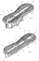
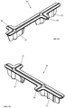
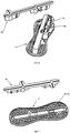
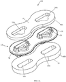
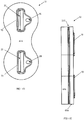
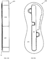
- FIG. 1A An example fin plug 10 is shown in Figures 1A, 1B , and 2A to 2H .
- the fin plug 10 of Figure 1A and 1B includes a top surface 15 and a bottom surface 20.
- the fin plug 10 further includes at least one fin cavity 25 for receiving a base element of a surfcraft fin (not shown).
- the at least one cavity 25 typically extends inwardly from at least one opening 30 in the top surface 15.
- the fin plug 10 also includes at least one hole 35 extending between the top surface 15 and the bottom surface 20, where the hole 35 is adapted to be filled with foam 40, first described with respect to Figure 3A and further with respect to Figures 10A to 10H .
- top surface 15 may be curved or otherwise shaped to correspond to the surface profile of a foam blank of a water craft or a surf craft in the position where the fin plug 10 is to be installed. Installation and other details of the fin plug are described in detail further below.
- Figures 1A and 1B also show that the fin plug 10 can include a plurality of holes 35 which extend between the top surface 15 and the bottom surface 20.
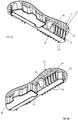
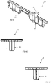
- Figures 2A to 2C show that the fin plug 10 can have a planar portion 16 which includes the top surface 15 and the bottom surface 20.
- the fin plug 10 can also include a base portion 18 which extends from the bottom surface 20 and surrounds the at least one fin cavity 25.
- the planar portion 16 can include a flange 19 extending laterally from the at least one opening 30 to an external perimeter 22 of the fin plug 10.
- one or more holes 35 can extend through the flange 19 of the planar portion 16. For example as can been seen in Figures 2A and 2C .
- the fin plug 10 can include two fin cavities 25 which extend inwardly from two separate openings 30 in the top surface 15 of the planar portion 16.
- the one or more holes 35 are located in the planar portion and have a length or depth of up to 0.5 cm. And yet in a further example, the holes can have a length of about 0.3 cm. As can be seen, the lengths or depths of the holes are substantially equivalent to the distance between the top surface 15 and the bottom surface of the flange 19.
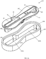
- Figures 2C and 2D further show that the base portion 18 of the fin plug 10 can include a plurality of rib elements 24 on an external surface 26 of the base portion 18.
- the rib elements 24 are described in detail below with respect to Figures 3A and 3B .
- the base portion 18 can also include a wall section and a floor section which are of substantially uniform thickness.
- the fin plug 10 can also include a fin retention means or otherwise termed a securing means.
- the fin retention means can include a grub screw (not shown) which is configured to be inserted and located into a screw hole 28, which typically extends from the top surface 15 and communicates with the at least one fin cavity 25 to hold a fin of a surfcraft therein.
- one of the grub screws can extend from the top surface 15 and communicate with one of said two fin cavities 25 and the other of the grub screws can extend from the top surface 15 and communicates with the other of said two fin cavities 25.
- the inclusion of the screw holes 28 (and the grub screws) in the fin plug described above are optional inclusions and may be done, primarily, to accommodate certain known surf craft fins which have fin tabs which extend into the fin cavities 25 and which are typically held in place by means of the grub screws.
- the fin tabs may not entirely fill the fin cavities and, consequently, there may be an empty space in the relevant fin cavity.
- a small cavity insert may (optionally) be inserted into the fin cavity to 'fill in' any such space when the water craft or surf craft is fitted with a fin/s and in use.
- FIGS 17A to 17G and 18A to 18G Examples of such, other cavity inserts are shown in Figures 17A to 17G and 18A to 18G .
- These fin cavity inserts in Figures 17A to 18G are different to the cavity inserts 50 first described below with respect to Figures 3A and 3B .
- the cavity inserts 50 are used during the manufacture of the water craft or surf craft.
- the fin retention means can also include a biasing means 45, which is configured to impose a lateral force on the base element of a fin (not shown) which is located in the cavity 25.
- the biasing means is described in PCT Patent Application No. PCT/AU2013/000738 , "A Fin Plug for Water Craft” filed 5 July 2013, the contents of which are incorporated herein by reference.
- the biasing means 45 includes a resilient biasing rod and a protruding member 46 (as shown in Figure 6 ) which cooperates with the biasing rod.
- the protruding member is typically configured to abut the base portion of the fin, when the fin is received in the fin cavity 25.
- the resilient biasing rod is formed of material selected from titanium, steel, marine grade steel, fiberglass, carbon fibre, plastic and reinforced engineering plastic.
- the fin plug 10 can also include a fin removal inhibiting means, described below with respect to Figure 8 .
- the fin removal inhibiting means can have a ledge portion, within said fin cavity 25, where the ledge portion is configured to overlie a section of the base element of the fin, when the fin is inserted within the cavity 25.
- the fin removal inhibiting means can substantially inhibit the removal of the fin from within the cavity 25, once inserted therein.
- the fin plug 10 may be formed of a thermoplastic, thermoset or plastic material, including but not limited to: a rigid thermoplastic, polyamide ('nylon'), acrylonitrile butadiene styrene ('ABS'), polyethylene, polyvinyl chloride ('PVC'), polyurethane, polybutylene terephthalate ('PBT') and polyethylene terephthalate ('PET').
- a rigid thermoplastic including but not limited to: a rigid thermoplastic, polyamide ('nylon'), acrylonitrile butadiene styrene ('ABS'), polyethylene, polyvinyl chloride ('PVC'), polyurethane, polybutylene terephthalate ('PBT') and polyethylene terephthalate ('PET').
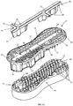
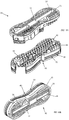
- FIGs 3A and 3B are exploded views of a composite foam and fin plug assembly.
- the fin plug assembly includes a fin plug 10 and a foam body 40.
- the fin plug 10 includes a plurality of holes 35 extending between the top surface 15 and the bottom surface 22.
- the foam body includes a plurality of hole in-fills 42 or projections. These in-fills 42 are positioned in the corresponding holes 35 of the fin plug 10.
- the foam body 40 may be formed about and within the fin plug 10 by a foam injection moulding process as described below with respect to Figures 10B to 10H and the manufacturing techniques further below.
- An example of a composite foam and fin plug assembly 90 is shown below with respect to Figure 10B .
- the foam body may be pre-formed separately to the fin plug.
- the pre-formed foam body 40 may then be suitably joined or bonded with an adhesive to the fin plug to form a composite foam and fin plug assembly.
- the pre-formed foam body 40 may be joined with the fin plug prior to installation in the water craft foam blank or separately installed as described further below.
- a purpose of the rib elements 24 is to enhance the strength and/or structural integrity of the fin plug 10.
- the rib elements 24 may also enhance the bonding of the fin plug and mechanical coupling of the fin plug to a surrounding foam body as shown in Figures 3A and 3B and further in Figures 10A to 10H , 15A to 15J and 16A to 16H .
- the rib elements 24 increase the surface area of interaction between the fin plug and the foam body / foam infill 40 which has advantages in bonding and transmitting of high forces between the fin, the fin plug, the foam body/ foam infill and the foam blank of the body of the water craft or surf craft.
- a cavity insert 50 (for example Figures 3A , 3B and 4A to 4H ) can be used to inhibit resinous material from entering the cavities 25 from the final stages of the manufacturing process.
- the final stages often includes inserting the fin plug 10 or the fin plug assembly (as described herein) into the underside of a surf craft and then pouring resinous material over the surface of the underside of the surf craft and, consequently, over the fin plug 10 or fin plug assembly.
- the resinous material can be kept out of the cavities.
- the cavity inserts can subsequently be removed (e.g.
- the cavity insert 50 when inserted into the fin cavity 25 is flush to the top surface 15 of the fin plug.
- the cavity inserts also feature cross hair markings 54, shown in Figures 3A and 3B , which may be used to aid in positioning cutting tools used in the installation process for the fin plug. Examples of installation procedures are described further below.
- the cavity insert may be made of the same or similar materials to that described above for the fin plug.
- the cavity insert is formed of a material which has poor adhesion to the resinous material, other adhesives and the foam.
- a person skilled in the art may select an appropriate material for the cavity insert and the application of the glass layer 60, resins, adhesives and fillers.
- Figures 4A to 4H show various views of the cavity insert 50
- Figures 3A and 3B show examples of how the cavity insert 50 can be inserted into the cavities 25.
- the cavity insert 50 is formed to have legs 51, which are formed so as to be received in the corresponding cavities 25, for instance by way of a friction fit or snap-fit.
- the cavity insert 50 can be elongate and is formed to cover both cavities 25, and further can also include a necked portion 52 to cover holes where grub screws or the like are to be inserted into.
- two separate cavity inserts one for each cavity 25 can also be used.
- Figure 5A shows an example fin plug assembly 10 before installation into a surfcraft.
- Figures 5B , 5C and 5D show examples of the fin plug 10 once installed, with a glass layer 60 which can be a layer or coating of fibreglass matt or fibres with impregnating resin.
- the cavity insert 50 is shown protecting the fin cavity 25 during the installation of the fin plug and application of the glass layers 60.
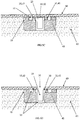
- Figure 5C is a cross-sectional transverse view through a fin cavity 25 of an installed fin plug 10 where the glass layer 60 covers the whole of the fin plug 10.
- a masking tape 55 or a similar shaped sticker may be applied to the fin cavity 25 opening 30 before the application of the glass layer 60, as described below with respect to figures 10A to 10H .
- FIG. 5D is another cross-sectional view of Figure 5C showing an example of the fin plug 10 after a glass routing process to provide the opening 30 to the fin cavity 25. It will be appreciated that the process of installation and manufacture, as described herein can allow for: increased bonding to the foam compared with a surface of the fin plug, an increased surface area for the glass layer 60 to cover the top surface 15 of the fin plug 10 and a flat installation (where there is no or limited tenting 64 of the glass 60).
- Figure 8 is a longitudinal, side cross-sectional view of Figure 5C where alternatively the flush cavity insert 50 of Figures 3A , 3B and 4A to 4H is inserted into the fin cavity 25.
- a fin removal inhibiting means 810 is shown.
- the fin removal inhibiting means may include a ledge portion, within said fin cavity, adapted to overlie a section of the base element of said fin or to engage with a base element or tab of the fin.
- Figure 9 is an alternate embodiment of Figure 8 where a raised top cavity insert 50A is inserted in the fin cavity 25.
- the raised top cavity insert 50A is not flush to the top surface 15 of the fin plug and accordingly causes a slight tenting 64 of the glass layer 60 over the raised top cavity insert 50A. This may provide an advantage in indicating the position of the cavity insert 50A when removing the glass layer 60 from above the cavity insert 50A.
- the fin plug 10 as described herein can include a ramp 70, lip, or the like formed at least partially or wholly around the surface of the cavity 25 opening 30.
- Examples of the ramp 70 are shown in Figures 10D , 11D , 11E and 12A .
- the ramp 70 includes a slightly raised surface from the top surface 15 of the fin plug 10.
- the ramp 70 forms a small ridge or raised lip about each fin cavity which helps to inhibit resinous material entering the cavity when the resin is poured or impregnated in the fibreglass matt to form the glass layer 60 , in the manufacturing process.
- FIGS 10A to 10H show that the ramp 70 can be integrated with the fin plug 10, it will be appreciated that the fin plug 10 can also include a cap which forms the ramp or raised lip (that is, as a part of the cavity insert 50, 50A), and thus the fin plug 10 can include a flat top surface 15 with a cap or the raised top cavity insert 50A which forms the ramp 70.
- the top surface with the cap or the flush cavity insert 50 can be completely flat and the cavities are routed after the board has been glassed.
- masking tape or a shaped blanking sticker/s may be applied to the opening 30 to prevent resinous material and other unwanted matter entering the fin cavity 25 during the water craft manufacture and fin plug installation.
- FIG 10A is an exploded view of the fin plug assembly according to a preferred embodiment of the second aspect of this invention.
- This fin plug assembly includes the fin plug 10 and the foam body 40.
- the fin plug 10 includes a plurality of holes 35 extending between the top surface 15 and the bottom surface 22.
- the foam body includes a plurality of hole in-fills 42 or projections. These in-fills 42 are positioned in the corresponding holes 35 of the fin plug 10.
- Figures 10B to 10H show examples of the composite fin plug assembly 90 including the fin plug10 and the foam body 40, in which the foam in-fills 42 of the foam body 40 are located within corresponding holes 35 in the fin plug 10.
- the fin plug assembly 90 is typically formed by inserting the fin plug 10 into a mould and liquid foam is injected into the mould so as to enable the foam to form and bond around the underside of the fin plug 10 and into the holes 35.
- the foam may then be heated to promote curing of the foam, thereby forming the composite foam and fin plug assembly 90.
- the foam body 40 is therefore, typically, moulded around the underside of the fin plug 10.
- the foam in-fills 42 occupy the holes 35 and, as shown in Figures 10B and 10D , a top end 44 of the foam in-fills 42 may be substantially flush with the top surface 15 of the fin plug 10 in order to effectively bond with glass layer 60.
- Figures 5C and 5D provide a cross-sectional view of the flange 19 with holes 35 and foam in-fills 42 bonding with the glass layer 60.
- the exposed top ends 44 of the foam in-fills result in improved adhesion with resinous material which is subsequently placed over the fin plug assembly 90. This is because resinous material generally forms a stronger chemical and mechanical bond with foam than with the hard plastic-type material typically used for a fin plug.
- the resinous material also may penetrate, in part at least, the foam in-fills 42 within the holes 35 so as to provide further mechanical keying to the applied glass layer 60.
- the glass layer 60 applied to the composite fin plug assembly is shown in Figures 5B , 5C , 5D , 8 and 9 . Accordingly the top surface 15 and flange 19 of the fin plug 10 is additionally bonded and additionally mechanically connected to the rest of the water craft body by the glass layer 60.
- the foam 42 within the holes 35 may not entirely fill the holes 35 to be flush with the top surface 15, but may be a sufficient filling of the hole to allow sufficient bonding with the glass layer 60.
- the glass layer 60 may also partially enter the holes 35.
- the foam infills 42 may also overfill the holes 35 such that foam 42 protrudes above the top surface 15.
- the foam infill 42 may protrude up to approximately 3 mm above the top surface 15 or more preferably up to approximately 1 mm above the top surface 15.
- the geometry or shape of the holes 35 with the foam in-fills 42 may be varied and still achieve the desired bonding and mechanical connection between the fin plug 10, the glass layer 60 and the rest of the body of the water craft.
- the shape, arrangement and number of the holes may be optimised and varied to improve the desired bonding and mechanical connections between the fin cavities and the glass layer 60, whilst maintaining the structural integrity of the planar portion 16 and the flange 19.
- the hole cross-sectional shape may be as shown in the Figures as: circular, semi-circular, portions of a circle and hexagonal.
- Further cross-sectional shapes include: slots, ellipses, rectangular, square, irregular shapes, polygonal and the like to provide the function required for providing a foam surface for bonding with the glass layer 60.
- planar portion 16 and the flange 19 may in part at least be a lattice of holes or apertures where the holes or the apertures may be of different shapes depending on: a form of the lattice or a framework which forms the lattice.
- the top surface 15 may alternatively be rippled or corrugated.
- the wells formed by the rippled surface or corrugations may contain foam for bonding with the glass layer 60.
- a use of a second moulding process may be used to apply the foam to holes which are blind.
- the holes are only open at one end at the top surface 15.
- the holes or apertures may only extend part of a thickness of the flange 19 or of the planar portion 16.
- blind holes may also include recesses in the top surface of the fin plug.
- Figures 19A to 20B show blind holes 1935 in the planar portion 16 and flange 19 of the fin plug.
- the corresponding foam body 1940, 40 has foam inflls 1942 for the blind holes which are shown as free standing to the foam bodies in Figures 19A and 20A . If the foam body is preformed, that is not injection moulded about the fin plug, then the foam infills 1942 for the blind holes may be supplied also as preformed foam infills 1942.
- the fin plug assembly 90 has exposed foam surfaces at the top and at the bottom of the assembly as well as around the sidewall(s) 92 of corresponding to the foam body 40. These exposed foam surfaces of the bottom and sidewalls 92 of the composite fin plug assembly 90 enhance the ability of the fin plug assembly to bond with resinous material, which is typically applied about the fin plug assembly 90 when it is being installed in a surf craft. Example installation procedures are described in detail further below.
- the foam used to form the foam body or foam infill 40 may be the same or substantially similar or compatible with that used for the foam used for foam blanks 62 of surfboards and water crafts.
- closed cell polyurethane (PU) closed cell expanded polystyrene (EPS) and closed cell extruded polystyrene foams may approximately range from 15 to 50 kg/m 3 .
- the foam body or foam infill 40 may be a higher strength and a higher stiffness closed foam that than that used for the foam blank of the water craft or the surf craft.
- Such higher strength or higher stiffness foams typically correspond to higher density foams compared with those used for water craft and surfboard blanks.
- a foam density of greater than approximately 50 kg/m 3 may be used or more preferably greater than approximately 70 kg/m 3 .
- the higher density foam may be of the same or similar type as that described above for the foam blanks as well as including epoxy foams, polyethylene terephthalate (PET) foams and polyvinyl chloride (PVC) foams. It will be readily appreciated that a person skilled in the art may select or design a suitable performing foam.
- a higher density foam for the foam body or foam infill compared with the foam blank may provide a number of advantages in the performance of the composite foam and fin plug assembly within the water craft or surf craft. For example a stiffer or higher strength foam within the holes 35 of the top surface may more effectively transmit and withstand higher forces in the bonding between the glass layer 60 and the composite foam and fin plug assembly. With respect to the sidewalls and bottom of the foam body of foam infill 40 the advantages are as disclosed in PCT Patent Application No. PCT/AU2008/001132 , "A Fin Plug Assembly and Method of Installation” filed 5 August 2008, the contents of which are incorporated herein by reference.
- the profile of the sidewalls 92 of the foam body 40 are shown in Figures 10A to 10H as being substantially the same as the external perimeter 22 of the flange 19 of the fin plug 10. It will be readily appreciated that the profile of the sidewalls 92 may also be convex, serrated (sawtooth), corrugated, undercut or otherwise recessed 94 to improve the function of the side wall and the interaction of the sidewall with the foam blank.
- Figure 19A and 19B show a foam body 1940 with a straight side wall 1992.
- FIGS 11A to 11H show an alternative composite fin plug assembly 100, in which the fin plug 110 includes first foam section 40A or layer and a second foam section 40B or layer.
- the fin plug 110 includes first foam section 40A or layer and a second foam section 40B or layer.
- a rigid (e.g. plastic) fin plug 110 is sandwiched and adhered between, or encapsulated by, foam sections 40A and 40B.
- the first foam section 40A has holes 25A there through which align with the fin cavities 25 of the fin plug 110.
- the second foam section 40B has recesses 18A adapted to receive base portions 18A of the fin plug 110.
- the fin plug 110 may be adhered to the foam sections 40A and 40B by means of a resinous material (or any other suitable adhesive material).
- the fin plug assembly 100 has exposed foam surfaces at the top and at the bottom of the assembly as well as around the sidewall(s) of it. These exposed foam surfaces enhance the ability of the fin plug assembly to bond with resinous material, which is typically located about the fin plug assembly 100 when it is being installed in a surf craft. As described for Figures 10 to 10D , the glass layer 60 bonds and mechanically connects the rest of the water craft body to the first foam section 40A, with the fin plug 110 top surface.
- the foam sections 40A, 40B may be injection moulded about the fin plug 110 as described above for Figures 10A to 10H .
- the fin plug assembly 100 shown in Figures 11A to 11H can be achieved by forming foam around the fin plug 110 (e.g. in a mould) or by bonding suitably two pre-cut pieces of foam to the fin plug 10.
- the first foam section 40A may have additional holes, slots or a connected arrangement of recesses (not shown) to further improve the bonding and the mechanical keying of the glass layer 60 to the alternative fin plug assembly 100.
- FIGs 12A to 12G show a further alternative composite fin plug assembly 200, having a fin plug 210 and a foam body 240.
- the foam body 240 has a plug cavity 250 adapted to receive the fin plug 210.
- the plug cavity includes a shallow cavity 250A, for receiving a planar portion 16C of the fin plug 210, and a deeper cavity 250B, for receiving a base portion 18C in which the fin plug 210.
- the fin plug 210 is positioned in the foam body 240 such that the foam body forms a wall of foam 244 or a peripheral ridge around the planar portion 16C fin plug 210.
- the fin plug 210 may be adhered to the foam body 240 by means of a resinous material (or any other suitable adhesive material).
- the fin plug assembly 200 has exposed foam surfaces at the top of the foam wall 244 and at the bottom of the assembly as well as around the sidewall(s) 1292 of the foam body 240. These exposed foam surfaces and the peripheral ridge 244 enhances the ability of the fin plug assembly to bond with resinous material, which is typically located about the fin plug assembly 200 when it is being installed in a surf craft.
- first foam section 40A may also be applied to the top surface of the planar portion 16C of the fin plug 210 in Figures 12A to 12G .
- An alternative first foam section or layer to the fin plug 210 may further improve the bonding and mechanical connection between the fin plug 210, the glass layer 60 and the rest of the body of the water craft or surf craft.
- Figures 19A, 19B , 20A and 20B show a peripheral ridge 344 of foam as an extension of the sidewall 92, 1992.
- the peripheral ridge 344 forms a wall of foam about the planar portion 16 of the flange 19 of the fin plug 10.
- the peripheral ridge 344 will also bond and mechanically connect with the glass layer 60 to further improve transmission of forces between the fin, fin plug 10 and the body of the water craft or surf craft.
- Figures 13A to 13G show another example of a fin plug 310.
- the holes 35 form a honeycomb like structure when the fin plug 310 is viewed from above (as in Figure 13B , for example).
- this particular example has a skirting 311 which forms around the external perimeter 22 of the fin plug 310.
- the skirting comprises a plurality of skirting elements 320 and a plurality of voids 321 between the skirting elements.
- the skirting 311 extends from the top surface 15 down at a length which is similar to the length of the cavities 25 within the base portion 18A (for securing the fins of a surf craft).
- the foam when filled with the foam, can fill in the voids 321 between the skirting elements 320.
- the outer perimeter 22 may have a rough surface of plastic skirting elements 320 and foam (in the adjoining voids).
- the foam may also fill in the holes of the honeycomb like structure about the fin cavities 25.
- the foam may also extend below the honeycomb structure into the volume bounded by the skirting 311 and the base portion 18A, as shown in Figure 13F .
- An alternative composite foam and fin plug assembly 310 can then be formed.
- Figures 14A to 14G show an example of a fin plug 410, having a plurality of holes 35, in which the fin plug has a solid border or perimeter 22.
- the holes 35 of the fin plug 410 are filled with foam, the foam is only visible on the top surface 15 and the bottom surface 20 of the composite foam and fin plug assembly.
- Figures 15A to 15J and Figures 16A to 16H are other embodiments of Figures 10A to 10H .
- Figures 15A to 15J and Figures 16A to 16H show further examples of a fin plug 510 having a plurality of holes 35.
- the holes of the fin plug 510 are configured to be filled with the foam 540 as shown in Figure 16A.
- Figures 16B to 16H show an example of a fin plug assembly 500 formed when the foam fills the holes of the fin plug 510 forming a foam body 540.
- the foam body 540 includes one or more channels 541 in a sidewall thereof.
- the channels 541 are moulded into the foam body 540 such that when the fin plug assembly 500 is inserted into the surf craft, any extra resin may flow upwards and outwards through the channels 541 and can be directed away from the surface of the foam blank.
- the one or more channels 541 are formed to make it easier for the assembly 500 to be inserted into the surf craft as the space in the channels 541 forms a void for excess resin when the fin plug assembly 500 is inserted.
- the channels 541 can include a ramped portion 543.
- Steps which may be taken in a manufacturing of the fin plug of the above Figures includes:
- the surfboard foam blank has been shaped with the fin/s position/s marked on the underside by the shaper of the surfboard.
- the foam blank may or may not have one or more glass layers.
- the steps to subsequently install the composite foam and fin plug assembly may include:
- An alternative to the first example manufacturing technique is to sacrifice the first cavity insert at step 6) when excess foam is being removed.
- a new cavity insert may be used to replace the cavity insert used in foam moulding.
- the new cavity insert would also have the cross hair markers 54 for guiding the positioning of the second template guide when using a router to obtain access to the fin cavities through the glass layer 60.
- a sacrificial cavity insert may then be used for the forming of the composite foam and fin plug assembly of the first example for the example Figures referenced. It may be particularly useful where the excess of foam to the top surface 15 is so much that the cavity insert cannot be seen.
- Sacrificial cavity inserts may also be used for the composite foam and fin plugs assemblies of Figures 11A to 11H and 12A to 12G where an alternate first foam layer 40A, without holes 25A, is applied or injection moulded to the top surface of the fin plug. The subsequent opening of the holes 25A for the fin cavities may be done with reduced care to the cavity insert integrity.
- a second cavity insert may be used to replace the sacrificed cavity insert, prior to installation into the foam blank.
- An alternative to the first example installation technique is the separate installation of the pre-formed foam body 40, 40B, 24, 540, 1940 into the foam blank prior to the fin plug 10. It has been described above that the foam body for the fin plug may be pre-formed to the fin plug. The pre-formed foam body may be separately installed into the foam blank with an appropriate installation jig as per steps II to IV of the first example. Then additional steps may be included to then separately install the fin plug by joining or otherwise adhering the fin plug to the foam body, which is already installed in the foam blank.
- the pre-formed foam body may be supplied as in an assembly kit that includes a fin plug, a pre-formed foam body, adhesive/s, cutting or routing templates, suitable installation jigs and instructions.
- the assembly kit may also be suitable for also assembling a composite foam and fin plug assembly which then may be installed into the foam blank as described for the first example installation technique.
Landscapes
- Chemical & Material Sciences (AREA)
- Engineering & Computer Science (AREA)
- Combustion & Propulsion (AREA)
- Mechanical Engineering (AREA)
- Ocean & Marine Engineering (AREA)
- Laminated Bodies (AREA)
- Moulds For Moulding Plastics Or The Like (AREA)
- Moulding By Coating Moulds (AREA)
Description
- The present invention relates to a fin plug, for installation in a water craft, such as a surfboard or the like, adapted to enable a fin to be removably attached to the water craft.
- A water craft, such as a surf-craft, particularly one on which a person stands, kneels or sits, when traversing water or riding a wave, generally has at least one fin in an underside of the craft, generally near the tail end of the craft. Such fins have a number of functions, including: enabling the craft to travel in a desired direction; facilitating the turning of the craft; preventing the craft from slipping sideways; and providing greater control over the movement of the craft, such as when riding a wave.
- The following discussion is directed mainly to surf-craft, such as surfboards, but it is to be understood that the discussion applies equally to other water craft (and surf craft) which are adapted to include fins, such as sail boards, paddle boards, kite surf boards, rescue boards, surf skis, kayaks, and the like.
- Some surf craft have the fins integrally formed on the surf craft and, for many years, this was the standard means for incorporating fins into such surfcraft. In the last twenty years or so, it has become more common for surfcraft to incorporate a removable fin or, more commonly, fin systems which include a number of removable fins. Such fin systems have numerous benefits, including enabling the fins to be removed for transportation and travelling, allowing damaged fins to be easily replaced and enabling fins of different shapes or styles to be selectively used. Such fin systems typically include at least one fin plug embedded into the underside of the surfcraft. This fin plug generally has at least one cavity adapted to receive a base portion (or a base element) of a surfcraft fin. The surfcraft fin is attached to the surfcraft by securing the base portion (or base element) of the fin into the cavity (or cavities) of the fin plug. There are numerous known fin systems which adopt this general arrangement.
- One such known fin system is described in
US 5,464,359 in the name of Fin Control Systems Pty Ltd. This system includes fins having 2 projecting base elements (or tabs) and, for each fin, two fin plugs installed in the underside of the surfcraft. Each of the fin plugs has a cavity for receiving one of the base elements. Each fin plug also includes means for securing the base element into the cavity. - An alternative fin system is described in
PCT/AU2008/001132 - Other known fin systems comprise a single fin plug, with a single cavity, for each fin. Typically, such a fin system has quite a large fin plug with an elongated fin cavity for receiving the base element of the fin. The fin plug of such systems also typically includes an upper flat portion having an opening from which the fin cavity extends inwardly and a flange section extending laterally about the opening. This flange section has a particular width. Extending downwardly from an underside of the flat upper portion is a body portion which surrounds the fin cavity. The shape of such a fin plug generally requires two cavities to be routed into the underside of the surfcraft in a two-step process. Firstly, a relatively wide, shallow cavity needs to be formed, the dimensions of which substantially correspond to the shape of the flange section. The depth of this first cavity will substantially correspond with the width of the flange section. Secondly, a narrow, deeper cavity needs to be formed in the first mentioned cavity, which is adapted to receive the body portion of the fin plug. As most surfcraft are designed to accommodate three fins, having to adopt this two-step process for forming each fin plug cavity in the surfcraft substantially slows down the installation process.
- Another problem with known fin plugs is that the bond formed between the fin plug and the resinous material with which the fin plug is typically secured within a surfboard blank can be, or can become, flawed, particularly as a result of pressure placed upon the surfcraft fin (which, in use, is connected to the fin plug). The means by which a fin plug is secured within a surfcraft is typically by means of a harden-able liquid resinous material between external surfaces of the fin plug and the wall(s) of the cavity into which the fin plug is inserted.
- In the fin system described in
US 5,464,359 , each of the fin plugs has a top surface (being the surface on which the opening to the cavity is located) and following installation in the surfcraft, this top surface is exposed, being flush with the surface of the underside of the surfcraft. - In the fin system described in PCT patent application number
PCT/AU2008/001132 WO 2009/021267 A1 , each fin plug has a top surface (again being the surface on which the opening to each cavity is located). Following installation in the surfcraft, this top surface is not exposed but, rather, sits under a fibreglass layer. This fiberglass layer above the fin plug top surface is generally continuous with the fibreglass layer of the underside of the surfcraft. The fiberglass layer which sits over the top surface of the fin plug enhances the secure fixation of the fin plug to the surfcraft. - A further problem with most known fin plugs (such as those disclosed in
US 5,464,359 ) is that, when installed in a surfcraft, they are surrounded by the relatively low density foam of which the surfcraft is formed. Such foam may not generally provide sufficient strength to support the loads placed upon the fin plug, due to forces applied to the attached fin, without some deformation, weakening or crushing of the surrounding foam over time. Such deformation or weakening of the foam may cause the fin plug to sink into the foam or to shift out of alignment, with consequential reduction in performance of the attached fin. This can also cause the fibreglass skin, in the vicinity of the fin plug, to crack or shatter. Also, when the fin plug sinks into the foam body, it can cause the top surface of the fin plug to separate from the adjoining fiberglass layer. - Surfcraft fins can be subject to very substantial forces (especially lateral forces) when the surfcraft is undergoing a turn or upon impact with some other object and these forces are then transferred to the corresponding fin plugs to which the fins are attached. These forces can place very substantial strains on the connections (formed of hardened resinous material) between the fin plug and the surfcraft. In turn, these connections can be weakened and, in some cases, the hardened resinous material can crack). These strains upon the abovementioned connections are generally in inverse proportion to the total area of the external surfaces of the fin plug. Accordingly, the smaller this area, the greater will be the strain placed upon the relevant connection.
- The present invention is directed towards ameliorating at least some of the above described problems associated with prior art fin plugs and, consequently, the methods of installing these. In particular, one object of the present invention is directed towards providing a fin plug assembly which is adapted to form a stronger bond with the resinous material with which it is secured to a surfcraft.
- Any reference herein to known prior art does not, unless the contrary indication appears, constitute an admission that such prior art is commonly known by those skilled in the art to which the invention relates, at the priority date of this application.
- According to a first aspect of the present invention, there is provided a composite fin plug mounting for a fin, as according to the accompanying claims.
- According to a first embodiment of the present invention, there is provided a composite fin plug mounting for a fin including:
- a fin plug of plastics material, having a top surface and a bottom surface surrounding at least one fin cavity in the fin plug for receiving a base element of the fin, the at least one fin cavity extending inwardly from at least one opening in the top surface;
- at least one of a recess or an aperture in the top surface;
characterised in that said at least one recess or aperture in the top surface is filled with a foam material, - Preferably, the fin plug includes a plurality of said holes extending between the top surface and the bottom surface. It is further preferred that the fin plug includes a planar portion, having said top surface and bottom surface, and a base portion extending from said bottom surface and surrounding said at least one fin cavity. The planar portion of the fin plug preferably includes a flange extending laterally from said a least one opening to an external perimeter.
- In a preferred embodiment, the fin plug includes two fin cavities for receiving two base elements of a water craft fin, said fin cavities extending inwardly from two openings in the top surface of said planar portion.
- It is particularly preferred that at least some of the holes extend through the flange of the planar portion.
- In a further aspect of the invention, a composite fin plug mounting as previously described is provided, wherein the fin plug has a honeycomb-like structure and comprises a plurality of apertures extending from the top surface to a base surface of a base portion of the fin plug, the base portion substantially including the at least one fin cavity, wherein the foam material is located in at least some of the plurality of apertures.. Preferably, the holes have a length of up to about 2 cm.
- Preferably, the holes are located in the planar portion of the fin plug and, in this embodiment; the holes have a length of up to about 0.5 cm. Preferably, the length of these holes is about 0.3 cm. As will be appreciated, the length of the holes is effectively the distance from the top surface to the bottom surface.
- It is further preferred that the base portion of said fin plug includes a plurality of rib elements on an external surface thereof. The main purpose of these rib elements is to enhance the strength and/or structural integrity of the fin plug. The rib elements may also enhance the bonding of the fin plug to a surrounding foam body. This base portion preferably includes a wall section and a floor section which are of substantially uniform thickness. A benefit of this uniform thickness is that it reduces the risk of any deformation of these sections of the fin plug during the cooling of the fin plug (following an injection moulding manufacturing process).
- The fin plug will typically contain fin retention means serving to keep the fin connected to the water craft (as desired).
- In one preferred embodiment, the fin retention means includes a grub screw located within a screw hole which extends from the top surface and communicates with said at least one fin cavity. In an embodiment of the invention in which the fin plug contains two fin cavities, the fin retention means of the fin plug may include one grub screw located within a screw hole which extends from the top surface and communicates with one of said two fin cavities. In a variation of this embodiment, the fin retention means may include two grub screws located within two screw holes, one of which extends from the top surface and communicates with one of said two fin cavities and the other of which extends from the top surface and communicates with the other of said two fin cavities.
- In an alternative preferred embodiment, the fin retention means includes a biasing means adapted to impose a lateral force on the base element of the fin located in said fin cavity. This biasing means may include a resilient biasing rod and a protruding member cooperating with the biasing rod, said protruding member being adapted to abut the base portion of said fin when received in said fin cavity. If the fin plug contains two fin cavities it is preferred that the biasing means is adapted only to impose the stated lateral force on the base element of the fin in one of the fin cavities (although it is possible that such a lateral force could be applied within both of the cavities). The biasing rod may be formed of any suitable material such as titanium, steel, marine grade steel, fiberglass, carbon fiber, plastic and reinforced engineering plastic.
- It is possible that the fin plug may incorporate both of the fin retention means described in the above two paragraphs.
- In a further preferred embodiment, the fin plug may further include fin removal inhibiting means including a ledge portion, within said fin cavity, adapted to overlie a section of the base element of said fin, thereby inhibiting removal of the fin.
- The fin plug may be formed of any suitable material, although plastic, thermosets and thermoplastic materials will generally be preferred. Suitable thermoplastic materials include polyamide ('nylon'), acrylonitrile butadiene styrene ('ABS'), polyurethane, polyvinyl chloride ('PVC'), polybutylene terepthalate ('PBT'), polyurethane and polyethylene terephthalate ('PET').
- According to a further aspect of this invention, there is provided a method of installing into a water craft a composite fin plug mounting as previously described including the steps: providing the composite fin plug mounting; protecting or blocking-up each fin cavity of the fin plug with a material to inhibit fluid material entering into said fin cavity; providing a water craft blank; making position markings on an underside of the water craft blank corresponding to the desired positions for the composite fin plug mounting in the water craft blank; route out a plug hole in the underside of water craft blank, said plug hole being adapted to receive the composite fin plug mounting; pouring a sufficient amount of resinous material into the plughole to form a layer of resinous material between the surfaces of the plug hole and the corresponding surfaces of the composite fin plug mounting; inserting the composite fin plug mounting into the plug hole so that the top surface of the mounting is substantially flush with an exterior surface of the water craft blank; connecting an installation jig to the composite fin plug mounting by inserting one or more tabs of said installation jig into the at least one fin cavity of the composite fin plug mounting; adjusting a cant angle and a toe angle for the fin as desired; securing the installation jig in a desired orientation for the desired cant and toe angles of the fin; once resinous material has set, removing the installation jig; applying fibreglass and coating of resinous material to external surfaces of the water craft blank, including over the top surface of the composite fin plug mounting; performing sanding of the external surface of the water craft as required; and removing a layer of fibreglass and resinous material above each fin cavity opening, including the protection or block-up for each fin cavity.
- In order to inhibit unwanted resinous material from entering into the fin cavity (or fin cavities) of the fin plug assembly, said cavities are covered or blocked. For instance, any such cavity may be blocked by having (removable) plastic in-fills inserted into them or a sticker sheet or tape applied to the opening of the cavity.
- Preferably, the material used to block up each cavity is a cavity in-fill which may be formed of the same material as the fin plug.
- Typically, the water craft is a surfboard and the shaped foam water craft blank will be a shaped foam surfboard blank.
- A detailed description of preferred embodiments of the present invention are given hereinafter, while referring to the figures .
-
Figures 1A and 1B are top perspective views of an example fin plug according to a preferred embodiment of the first aspect of this invention; -
Figures 2A and 2B are further top perspective views of the example fin plug ofFigures 1A and 1B . -
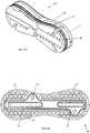
Figures 2C and 2D are bottom perspective views of the example fin plug ofFigures 2A and 2B ; -
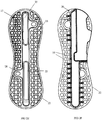
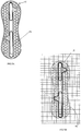
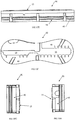
Figure 2E is a top plan view of the example fin plug ofFigures 2A and 2B ; -
Figure 2F is a bottom view of the example fin plug ofFigures 2A and 2B ; -
Figure 2G is a front view of the example fin plug ofFigures 2A and 2B ; -
Figure 2H is a side view of the example fin plug ofFigures 2A and 2B ; -
Figure 3A is an exploded perspective view of an example composite foam and fin plug assembly according to the invention and including a cavity insert for attachment to the fin plug assembly; -
Figure 3B is another exploded perspective view of an the example fin plug assembly shown inFigure 3A , again showing the cavity insert for attachment to the fin plug assembly; -
Figures 4A and 4B are top perspective views of an example cavity insert which can be used with the fin plug and/or fin plug assembly described herein; -
Figure 4C is a top view of the example cavity insert ofFigures 4A and 4B ; -
Figure 4D is a side view of the example cavity insert ofFigures 4A and 4B ; -
Figure 4E is a bottom view of the example cavity insert ofFigures 4A and 4B ; -
Figure 4F is a bottom perspective view of the example cavity insert ofFigures 4A and 4B ; -
Figures 4G and 4H are front end and rear end views of the example cavity insert ofFigures 4A and 4B ; -
Figure 5A is a top plan view of an example composite foam and fin plug assembly with a cavity insert prior to installation into a surf craft; -
Figure 5B is a top plan view of the example fin plug assembly ofFigure 5A installed within a section of a surf craft. -
Figure 5C is a cross-sectional view transversely through a fin cavity of another example of a composite foam and fin plug assembly; -
Figure 5D is another transverse cross-sectional view of the fin plug assembly as shown inFigure 5C , after the opening to the fin cavity has been restored; -
Figures 6 and 7 are further perspective views of the fin plug and the cavity insert; -
Figure 8 is a cross-sectional longitudinal side view ofFigure 5C where alternatively the flush cavity insert ofFigures 3A ,3B and4A to 4H is inserted into the fin cavity; -
Figure 9 is an alternate embodiment ofFigure 8 where a raised top cavity insert is inserted in the fin cavity; -
Figure 10A is an exploded perspective view of another example composite foam and fin plug assembly according to an embodiment of the second aspect of this invention; -
Figure 10B is a front perspective view of the example fin plug assembly ofFigure 10A ; -
Figure 10C is a back perspective view of the example fin plug assembly ofFigure 10A ; -
Figure 10D is a top plan view of the example fin plug assembly ofFigure 10A ; -
Figure 10E is a side view of the example fin plug assembly ofFigure 10A ; -
Figure 10F is a bottom view of the example fin plug assembly ofFigure 10A ; -
Figures 10G and 10H are front end and rear end views of the fin plug ofFigure 10A ; -
Figure 11A is an exploded perspective view of yet another example fin plug assembly as described herein; -
Figure 11B is a top perspective view of the example fin plug assembly ofFigure 11A ; -
Figure 11C is a bottom perspective view of the example fin plug assembly ofFigure 11A ; -
Figure 11D is top plan view of the example fin plug assembly ofFigure 11A ; -
Figures 11E and11G are side views of the example fin plug assembly ofFigure 11A ; -
Figure 11F is a bottom view of the example fin plug assembly ofFigure 11A ; -
Figure 11G is a side view of the example fin plug assembly ofFigure 11A ; -
Figure 11H is a front end view of the example fin plug assembly ofFigure 11A ; -
Figure 12A is an exploded perspective view of another example fin plug assembly as described herein; -
Figure 12B is a top perspective view of the example fin plug assembly ofFigure 12A ; -
Figure 12C is a top plan view of the example fin plug assembly ofFigure 12A ; -
Figures 12D and12F are side views of the example fin plug assembly ofFigure 12A ; -
Figure 12E is a bottom view of the example fin plug assembly ofFigure 12A ; -
Figure 12G is a front end view of the example fin plug ofFigure 12A ; -
Figures 13A to 13G show a further example of a fin plug according to an alternative embodiment of the first aspect of this invention. In particular,Figure 13A is a top perspective view,Figure 13B is a plan view,Figure 13C is an end front view,Figure 13D is a side view from the left,Figure 13E is an end rear view,Figure 13F is a bottom perspective view, andFigure 13G is a bottom view; -
Figures 14A to 14G show yet a further example of another fin plug according to another alternative embodiment of the first aspect of this invention. In particular,Figure 14A is a top perspective view,Figure 14B is a view from below;Figure 14C is a front end view,Figure 14D is a side view,Figure 14E is a back end view, andFigure 14F is a plan view; -
Figure 15A to 15J show yet another example of another fin plug according to another alternative embodiment of the first aspect of this invention. In particular,Figure 15A is a top perspective view,Figure 15B is a view from below,Figure 15C is another top perspective view,Figure 15D is a front end view,Figure 15E is a side view from the left,Figure 15F is rear end view,Figure 15G is another side view from the right,Figure 15H is a bottom perspective view,Figure 15I is a plan view, andFigure 15J is another bottom perspective view; -
Figure 16A is an exploded perspective view of another example of the fin plug assembly according to an alternative embodiment ofFigures 10A and 10B ; -
Figures 16B to 16H show the example fin plug assembly ofFigure 16A , once formed. In particular,Figure 16B is a top perspective view,Figure 16C is a bottom perspective view,Figure 16D is a side view from the left,Figure 16E is a plan view,Figure 16F is a side view from the right,Figure 16G is an end view, andFigure 16H is a bottom view; and, -
Figures 17A to 18G are views of examples of other cavity inserts which may be used, in certain circumstances (as described further below), in some embodiments of the invention. In particular,Figure 17A is a rear perspective view of an example cavity insert,Figure 17B is a front perspective view,Figure 17C is a bottom view,Figure 17D is a plan view,Figure 17E is a left side view,Figure 17F is a right side view, andFigure 17G is an end view of the example cavity insert ofFigure 17A . Further,Figure 18A is a back perspective view of an example cavity insert with a tag,Figure 18B is an example front perspective view,Figure 18C is a plan view,Figure 18D is a left side view,Figure 18E is a right side view,Figure 18F is an end view, andFigure 18G is a bottom view of the example cavity insert ofFigure 18A . -
Figures 19A and 19B are respective exploded and assembled perspective views of a composite foam fin plug with a straight side wall and a peripheral ridge about the fin plug flange. -
Figures 20A and 20B are an alternate embodiment ofFigures 19A and 19B , without the straight side wall of the foam body. - An
example fin plug 10 is shown inFigures 1A, 1B , and2A to 2H . - The fin plug 10 of
Figure 1A and 1B includes atop surface 15 and abottom surface 20. The fin plug 10 further includes at least onefin cavity 25 for receiving a base element of a surfcraft fin (not shown). The at least onecavity 25 typically extends inwardly from at least oneopening 30 in thetop surface 15. The fin plug 10 also includes at least onehole 35 extending between thetop surface 15 and thebottom surface 20, where thehole 35 is adapted to be filled withfoam 40, first described with respect toFigure 3A and further with respect toFigures 10A to 10H . - It will be readily appreciated that the
top surface 15 may be curved or otherwise shaped to correspond to the surface profile of a foam blank of a water craft or a surf craft in the position where thefin plug 10 is to be installed. Installation and other details of the fin plug are described in detail further below. -
Figures 1A and 1B also show that thefin plug 10 can include a plurality ofholes 35 which extend between thetop surface 15 and thebottom surface 20. Furthermore,Figures 2A to 2C show that thefin plug 10 can have aplanar portion 16 which includes thetop surface 15 and thebottom surface 20. The fin plug 10 can also include abase portion 18 which extends from thebottom surface 20 and surrounds the at least onefin cavity 25. - In one particular example, the
planar portion 16 can include aflange 19 extending laterally from the at least oneopening 30 to anexternal perimeter 22 of thefin plug 10. Thus, in this particular example, one ormore holes 35 can extend through theflange 19 of theplanar portion 16. For example as can been seen inFigures 2A and2C . - It will further be appreciated that the
fin plug 10 can include twofin cavities 25 which extend inwardly from twoseparate openings 30 in thetop surface 15 of theplanar portion 16. - According to one particular example, the one or
more holes 35 are located in the planar portion and have a length or depth of up to 0.5 cm. And yet in a further example, the holes can have a length of about 0.3 cm. As can be seen, the lengths or depths of the holes are substantially equivalent to the distance between thetop surface 15 and the bottom surface of theflange 19. -
Figures 2C and 2D further show that thebase portion 18 of thefin plug 10 can include a plurality ofrib elements 24 on anexternal surface 26 of thebase portion 18. Therib elements 24 are described in detail below with respect toFigures 3A and3B . Notably, thebase portion 18 can also include a wall section and a floor section which are of substantially uniform thickness. - The fin plug 10 can also include a fin retention means or otherwise termed a securing means. In one particular example, as shown in
Figures 1A, 1B ,2A, and 2B the fin retention means can include a grub screw (not shown) which is configured to be inserted and located into ascrew hole 28, which typically extends from thetop surface 15 and communicates with the at least onefin cavity 25 to hold a fin of a surfcraft therein. - Notably, there can be provided two or more grub screws located within respective two or more screw holes 28. In this particular example, one of the grub screws can extend from the
top surface 15 and communicate with one of said twofin cavities 25 and the other of the grub screws can extend from thetop surface 15 and communicates with the other of said twofin cavities 25. - The inclusion of the screw holes 28 (and the grub screws) in the fin plug described above are optional inclusions and may be done, primarily, to accommodate certain known surf craft fins which have fin tabs which extend into the
fin cavities 25 and which are typically held in place by means of the grub screws. When such known surf craft fins are secured to the fin plug, the fin tabs may not entirely fill the fin cavities and, consequently, there may be an empty space in the relevant fin cavity. In order to minimise or avoid the presence of any such empty space, a small cavity insert may (optionally) be inserted into the fin cavity to 'fill in' any such space when the water craft or surf craft is fitted with a fin/s and in use. Examples of such, other cavity inserts are shown inFigures 17A to 17G and 18A to 18G . These fin cavity inserts inFigures 17A to 18G are different to the cavity inserts 50 first described below with respect toFigures 3A and3B . In contrast the cavity inserts 50 are used during the manufacture of the water craft or surf craft. - In yet a further example, as shown particularly in
Figures 1B ,6 and 7 , the fin retention means can also include a biasing means 45, which is configured to impose a lateral force on the base element of a fin (not shown) which is located in thecavity 25. The biasing means is described in PCT Patent Application No.PCT/AU2013/000738 - Typically, the biasing means 45 includes a resilient biasing rod and a protruding member 46 (as shown in
Figure 6 ) which cooperates with the biasing rod. The protruding member is typically configured to abut the base portion of the fin, when the fin is received in thefin cavity 25. According to one particular example, the resilient biasing rod is formed of material selected from titanium, steel, marine grade steel, fiberglass, carbon fibre, plastic and reinforced engineering plastic. - In yet a further example of the above reference, the
fin plug 10 can also include a fin removal inhibiting means, described below with respect toFigure 8 .. The fin removal inhibiting means can have a ledge portion, within saidfin cavity 25, where the ledge portion is configured to overlie a section of the base element of the fin, when the fin is inserted within thecavity 25. Thus it can be appreciated that the fin removal inhibiting means can substantially inhibit the removal of the fin from within thecavity 25, once inserted therein. - It will be appreciated by persons skilled in the art that the
fin plug 10 may be formed of a thermoplastic, thermoset or plastic material, including but not limited to: a rigid thermoplastic, polyamide ('nylon'), acrylonitrile butadiene styrene ('ABS'), polyethylene, polyvinyl chloride ('PVC'), polyurethane, polybutylene terephthalate ('PBT') and polyethylene terephthalate ('PET'). -
Figures 3A and3B are exploded views of a composite foam and fin plug assembly. The fin plug assembly includes afin plug 10 and afoam body 40. As described above, thefin plug 10 includes a plurality ofholes 35 extending between thetop surface 15 and thebottom surface 22. As shown inFigure 3A and3B , the foam body includes a plurality of hole in-fills 42 or projections. These in-fills 42 are positioned in the correspondingholes 35 of thefin plug 10. - The
foam body 40 may be formed about and within thefin plug 10 by a foam injection moulding process as described below with respect toFigures 10B to 10H and the manufacturing techniques further below. An example of a composite foam andfin plug assembly 90 is shown below with respect toFigure 10B . Alternatively the foam body may be pre-formed separately to the fin plug. Thepre-formed foam body 40 may then be suitably joined or bonded with an adhesive to the fin plug to form a composite foam and fin plug assembly. Thepre-formed foam body 40 may be joined with the fin plug prior to installation in the water craft foam blank or separately installed as described further below. - A purpose of the
rib elements 24 is to enhance the strength and/or structural integrity of thefin plug 10. Therib elements 24 may also enhance the bonding of the fin plug and mechanical coupling of the fin plug to a surrounding foam body as shown inFigures 3A and3B and further inFigures 10A to 10H ,15A to 15J and16A to 16H . In those Figures it is readily apparent that therib elements 24 increase the surface area of interaction between the fin plug and the foam body /foam infill 40 which has advantages in bonding and transmitting of high forces between the fin, the fin plug, the foam body/ foam infill and the foam blank of the body of the water craft or surf craft. - It will be appreciated that, when in the final stages of manufacturing the surf craft, as described below, a cavity insert 50 (for example
Figures 3A ,3B and4A to 4H ) can be used to inhibit resinous material from entering thecavities 25 from the final stages of the manufacturing process. The final stages often includes inserting thefin plug 10 or the fin plug assembly (as described herein) into the underside of a surf craft and then pouring resinous material over the surface of the underside of the surf craft and, consequently, over thefin plug 10 or fin plug assembly. Thus, by inserting acavity insert 50 into thecavities 25, prior to the pouring of the resinous material; the resinous material can be kept out of the cavities. The cavity inserts can subsequently be removed (e.g. by sanding or routing) enabling the cavities to be revealed. Thecavity insert 50 when inserted into thefin cavity 25 is flush to thetop surface 15 of the fin plug. The cavity inserts also featurecross hair markings 54, shown inFigures 3A and3B , which may be used to aid in positioning cutting tools used in the installation process for the fin plug. Examples of installation procedures are described further below. - The cavity insert may be made of the same or similar materials to that described above for the fin plug. Preferably the cavity insert is formed of a material which has poor adhesion to the resinous material, other adhesives and the foam. Alternatively a person skilled in the art may select an appropriate material for the cavity insert and the application of the
glass layer 60, resins, adhesives and fillers. -
Figures 4A to 4H show various views of thecavity insert 50, andFigures 3A and3B show examples of how thecavity insert 50 can be inserted into thecavities 25. Thus, in this particular example, thecavity insert 50 is formed to havelegs 51, which are formed so as to be received in the correspondingcavities 25, for instance by way of a friction fit or snap-fit. - Furthermore, as shown in
Figures 3A to 4G , thecavity insert 50 can be elongate and is formed to cover bothcavities 25, and further can also include anecked portion 52 to cover holes where grub screws or the like are to be inserted into. However, it will be appreciated that two separate cavity inserts (one for each cavity 25) can also be used. -
Figure 5A shows an examplefin plug assembly 10 before installation into a surfcraft.Figures 5B ,5C and 5D show examples of thefin plug 10 once installed, with aglass layer 60 which can be a layer or coating of fibreglass matt or fibres with impregnating resin. In the plan view ofFigure 5B thecavity insert 50 is shown protecting thefin cavity 25 during the installation of the fin plug and application of the glass layers 60.Figure 5C is a cross-sectional transverse view through afin cavity 25 of an installedfin plug 10 where theglass layer 60 covers the whole of thefin plug 10. A masking tape 55 or a similar shaped sticker may be applied to thefin cavity 25opening 30 before the application of theglass layer 60, as described below with respect tofigures 10A to 10H . Alternatively thecavity insert 50 may also be used. It will be appreciated that theholes 35 together with thefoam 42 create a surface which can better adhere to theglass layer 60 as described below with respect toFigures 10A to 10H .Figure 5D is another cross-sectional view ofFigure 5C showing an example of thefin plug 10 after a glass routing process to provide theopening 30 to thefin cavity 25. It will be appreciated that the process of installation and manufacture, as described herein can allow for: increased bonding to the foam compared with a surface of the fin plug, an increased surface area for theglass layer 60 to cover thetop surface 15 of thefin plug 10 and a flat installation (where there is no orlimited tenting 64 of the glass 60). -
Figure 8 is a longitudinal, side cross-sectional view ofFigure 5C where alternatively theflush cavity insert 50 ofFigures 3A ,3B and4A to 4H is inserted into thefin cavity 25. A finremoval inhibiting means 810 is shown. The fin removal inhibiting means may include a ledge portion, within said fin cavity, adapted to overlie a section of the base element of said fin or to engage with a base element or tab of the fin. -
Figure 9 is an alternate embodiment ofFigure 8 where a raised top cavity insert 50A is inserted in thefin cavity 25. The raised top cavity insert 50A is not flush to thetop surface 15 of the fin plug and accordingly causes aslight tenting 64 of theglass layer 60 over the raisedtop cavity insert 50A. This may provide an advantage in indicating the position of the cavity insert 50A when removing theglass layer 60 from above thecavity insert 50A. - Notably, the
fin plug 10 as described herein can include aramp 70, lip, or the like formed at least partially or wholly around the surface of thecavity 25opening 30. Examples of theramp 70 are shown inFigures 10D ,11D ,11E and12A . Thus, theramp 70 includes a slightly raised surface from thetop surface 15 of thefin plug 10. Theramp 70 forms a small ridge or raised lip about each fin cavity which helps to inhibit resinous material entering the cavity when the resin is poured or impregnated in the fibreglass matt to form theglass layer 60 , in the manufacturing process. - Although
Figures 10A to 10H show that theramp 70 can be integrated with thefin plug 10, it will be appreciated that thefin plug 10 can also include a cap which forms the ramp or raised lip (that is, as a part of thecavity insert fin plug 10 can include a flattop surface 15 with a cap or the raisedtop cavity insert 50A which forms theramp 70. Alternatively, the top surface with the cap or theflush cavity insert 50 can be completely flat and the cavities are routed after the board has been glassed. Alternatively masking tape or a shaped blanking sticker/s may be applied to theopening 30 to prevent resinous material and other unwanted matter entering thefin cavity 25 during the water craft manufacture and fin plug installation. - Further examples of possible manufacturing and installation techniques of the fin plugs shown in the Figures are described below.
-
Figure 10A is an exploded view of the fin plug assembly according to a preferred embodiment of the second aspect of this invention. This fin plug assembly includes thefin plug 10 and thefoam body 40. As described above, thefin plug 10 includes a plurality ofholes 35 extending between thetop surface 15 and thebottom surface 22. As shown inFigure 10A , the foam body includes a plurality of hole in-fills 42 or projections. These in-fills 42 are positioned in the correspondingholes 35 of thefin plug 10. -
Figures 10B to 10H show examples of the compositefin plug assembly 90 including the fin plug10 and thefoam body 40, in which the foam in-fills 42 of thefoam body 40 are located within correspondingholes 35 in thefin plug 10. - The
fin plug assembly 90 is typically formed by inserting thefin plug 10 into a mould and liquid foam is injected into the mould so as to enable the foam to form and bond around the underside of thefin plug 10 and into theholes 35. The foam may then be heated to promote curing of the foam, thereby forming the composite foam andfin plug assembly 90. Thefoam body 40 is therefore, typically, moulded around the underside of thefin plug 10. Thus, as described herein, together thefoam body 40 and thefin plug 10 form the composite foam and fin plug assembly 90 (as shown inFigures 10B to 10H ). - The foam in-
fills 42 occupy theholes 35 and, as shown inFigures 10B and10D , atop end 44 of the foam in-fills 42 may be substantially flush with thetop surface 15 of thefin plug 10 in order to effectively bond withglass layer 60.Figures 5C and 5D provide a cross-sectional view of theflange 19 withholes 35 and foam in-fills 42 bonding with theglass layer 60. The exposed top ends 44 of the foam in-fills result in improved adhesion with resinous material which is subsequently placed over thefin plug assembly 90. This is because resinous material generally forms a stronger chemical and mechanical bond with foam than with the hard plastic-type material typically used for a fin plug. The resinous material also may penetrate, in part at least, the foam in-fills 42 within theholes 35 so as to provide further mechanical keying to the appliedglass layer 60. Theglass layer 60 applied to the composite fin plug assembly is shown inFigures 5B ,5C ,5D ,8 and 9 . Accordingly thetop surface 15 andflange 19 of thefin plug 10 is additionally bonded and additionally mechanically connected to the rest of the water craft body by theglass layer 60. - It will be readily appreciated that the
foam 42 within theholes 35 may not entirely fill theholes 35 to be flush with thetop surface 15, but may be a sufficient filling of the hole to allow sufficient bonding with theglass layer 60. Theglass layer 60 may also partially enter theholes 35. Alternatively it will also be appreciated that the foam infills 42 may also overfill theholes 35 such thatfoam 42 protrudes above thetop surface 15. For example thefoam infill 42 may protrude up to approximately 3 mm above thetop surface 15 or more preferably up to approximately 1 mm above thetop surface 15. - It will also be readily appreciated that the geometry or shape of the
holes 35 with the foam in-fills 42 may be varied and still achieve the desired bonding and mechanical connection between thefin plug 10, theglass layer 60 and the rest of the body of the water craft. The shape, arrangement and number of the holes may be optimised and varied to improve the desired bonding and mechanical connections between the fin cavities and theglass layer 60, whilst maintaining the structural integrity of theplanar portion 16 and theflange 19. For example the hole cross-sectional shape may be as shown in the Figures as: circular, semi-circular, portions of a circle and hexagonal. Further cross-sectional shapes include: slots, ellipses, rectangular, square, irregular shapes, polygonal and the like to provide the function required for providing a foam surface for bonding with theglass layer 60. Alternatively theplanar portion 16 and theflange 19 may in part at least be a lattice of holes or apertures where the holes or the apertures may be of different shapes depending on: a form of the lattice or a framework which forms the lattice. - The
top surface 15 may alternatively be rippled or corrugated. The wells formed by the rippled surface or corrugations may contain foam for bonding with theglass layer 60. - It will also be further appreciated that a use of a second moulding process, described in detail below, may be used to apply the foam to holes which are blind. For example the holes are only open at one end at the
top surface 15. In other words the holes or apertures may only extend part of a thickness of theflange 19 or of theplanar portion 16. Alternatively blind holes may also include recesses in the top surface of the fin plug.Figures 19A to 20B showblind holes 1935 in theplanar portion 16 andflange 19 of the fin plug. The correspondingfoam body foam inflls 1942 for the blind holes which are shown as free standing to the foam bodies inFigures 19A and20A . If the foam body is preformed, that is not injection moulded about the fin plug, then the foam infills 1942 for the blind holes may be supplied also as preformedfoam infills 1942. - As can be seen from the
Figures 10D to 10H , thefin plug assembly 90 has exposed foam surfaces at the top and at the bottom of the assembly as well as around the sidewall(s) 92 of corresponding to thefoam body 40. These exposed foam surfaces of the bottom and sidewalls 92 of the compositefin plug assembly 90 enhance the ability of the fin plug assembly to bond with resinous material, which is typically applied about thefin plug assembly 90 when it is being installed in a surf craft. Example installation procedures are described in detail further below. - The foam used to form the foam body or
foam infill 40 may be the same or substantially similar or compatible with that used for the foam used forfoam blanks 62 of surfboards and water crafts. For example closed cell polyurethane (PU) closed cell expanded polystyrene (EPS) and closed cell extruded polystyrene foams. The density of such foams may approximately range from 15 to 50 kg/m3. - In an alternate embodiment the foam body or
foam infill 40 may be a higher strength and a higher stiffness closed foam that than that used for the foam blank of the water craft or the surf craft. Such higher strength or higher stiffness foams typically correspond to higher density foams compared with those used for water craft and surfboard blanks. For example a foam density of greater than approximately 50 kg/m3 may be used or more preferably greater than approximately 70 kg/m3. - The higher density foam may be of the same or similar type as that described above for the foam blanks as well as including epoxy foams, polyethylene terephthalate (PET) foams and polyvinyl chloride (PVC) foams. It will be readily appreciated that a person skilled in the art may select or design a suitable performing foam.
- A higher density foam for the foam body or foam infill compared with the foam blank may provide a number of advantages in the performance of the composite foam and fin plug assembly within the water craft or surf craft. For example a stiffer or higher strength foam within the
holes 35 of the top surface may more effectively transmit and withstand higher forces in the bonding between theglass layer 60 and the composite foam and fin plug assembly. With respect to the sidewalls and bottom of the foam body offoam infill 40 the advantages are as disclosed in PCT Patent Application No.PCT/AU2008/001132 - The profile of the
sidewalls 92 of thefoam body 40 are shown inFigures 10A to 10H as being substantially the same as theexternal perimeter 22 of theflange 19 of thefin plug 10. It will be readily appreciated that the profile of thesidewalls 92 may also be convex, serrated (sawtooth), corrugated, undercut or otherwise recessed 94 to improve the function of the side wall and the interaction of the sidewall with the foam blank.Figure 19A and 19B show afoam body 1940 with astraight side wall 1992. -
Figures 11A to 11H show an alternative compositefin plug assembly 100, in which thefin plug 110 includesfirst foam section 40A or layer and asecond foam section 40B or layer. Thus, in this particular example, a rigid (e.g. plastic)fin plug 110 is sandwiched and adhered between, or encapsulated by,foam sections first foam section 40A hasholes 25A there through which align with thefin cavities 25 of thefin plug 110. Thesecond foam section 40B hasrecesses 18A adapted to receivebase portions 18A of thefin plug 110. Thefin plug 110 may be adhered to thefoam sections - As can be seen from the
Figures 11A to 11H , thefin plug assembly 100 has exposed foam surfaces at the top and at the bottom of the assembly as well as around the sidewall(s) of it. These exposed foam surfaces enhance the ability of the fin plug assembly to bond with resinous material, which is typically located about thefin plug assembly 100 when it is being installed in a surf craft. As described forFigures 10 to 10D , theglass layer 60 bonds and mechanically connects the rest of the water craft body to thefirst foam section 40A, with thefin plug 110 top surface. - Alternatively the
foam sections fin plug 110 as described above forFigures 10A to 10H . It will be appreciated that thefin plug assembly 100 shown inFigures 11A to 11H can be achieved by forming foam around the fin plug 110 (e.g. in a mould) or by bonding suitably two pre-cut pieces of foam to thefin plug 10. It will also be appreciated that thefirst foam section 40A may have additional holes, slots or a connected arrangement of recesses (not shown) to further improve the bonding and the mechanical keying of theglass layer 60 to the alternativefin plug assembly 100. -
Figures 12A to 12G show a further alternative compositefin plug assembly 200, having afin plug 210 and afoam body 240. Thefoam body 240 has aplug cavity 250 adapted to receive thefin plug 210. As can be seen fromFigure 12A , the plug cavity includes ashallow cavity 250A, for receiving aplanar portion 16C of thefin plug 210, and adeeper cavity 250B, for receiving abase portion 18C in which thefin plug 210. Thefin plug 210 is positioned in thefoam body 240 such that the foam body forms a wall offoam 244 or a peripheral ridge around theplanar portion 16C fin plug 210. Thefin plug 210 may be adhered to thefoam body 240 by means of a resinous material (or any other suitable adhesive material). As can be seen from theFigures 12A to 12G , thefin plug assembly 200 has exposed foam surfaces at the top of thefoam wall 244 and at the bottom of the assembly as well as around the sidewall(s) 1292 of thefoam body 240. These exposed foam surfaces and theperipheral ridge 244 enhances the ability of the fin plug assembly to bond with resinous material, which is typically located about thefin plug assembly 200 when it is being installed in a surf craft. - It will be readily appreciated that an alternative
first foam section 40A may also be applied to the top surface of theplanar portion 16C of thefin plug 210 inFigures 12A to 12G . An alternative first foam section or layer to thefin plug 210 may further improve the bonding and mechanical connection between thefin plug 210, theglass layer 60 and the rest of the body of the water craft or surf craft. -
Figures 19A, 19B ,20A and 20B show aperipheral ridge 344 of foam as an extension of thesidewall peripheral ridge 344 forms a wall of foam about theplanar portion 16 of theflange 19 of thefin plug 10. Theperipheral ridge 344 will also bond and mechanically connect with theglass layer 60 to further improve transmission of forces between the fin,fin plug 10 and the body of the water craft or surf craft. -
Figures 13A to 13G show another example of afin plug 310. In this particular example, theholes 35 form a honeycomb like structure when thefin plug 310 is viewed from above (as inFigure 13B , for example). Further, this particular example has a skirting 311 which forms around theexternal perimeter 22 of thefin plug 310. The skirting comprises a plurality of skirtingelements 320 and a plurality ofvoids 321 between the skirting elements. As can be seen, the skirting 311 extends from thetop surface 15 down at a length which is similar to the length of thecavities 25 within thebase portion 18A (for securing the fins of a surf craft). It will be appreciated that in this particular example, when filled with the foam, the foam can fill in thevoids 321 between the skirtingelements 320. Once filled, theouter perimeter 22 may have a rough surface ofplastic skirting elements 320 and foam (in the adjoining voids). In addition the foam may also fill in the holes of the honeycomb like structure about thefin cavities 25. The foam may also extend below the honeycomb structure into the volume bounded by the skirting 311 and thebase portion 18A, as shown inFigure 13F . An alternative composite foam and fin plug assembly 310 can then be formed. - In yet a further example,
Figures 14A to 14G show an example of afin plug 410, having a plurality ofholes 35, in which the fin plug has a solid border orperimeter 22. In this particular example, when theholes 35 of thefin plug 410 are filled with foam, the foam is only visible on thetop surface 15 and thebottom surface 20 of the composite foam and fin plug assembly. -
Figures 15A to 15J andFigures 16A to 16H are other embodiments ofFigures 10A to 10H .Figures 15A to 15J andFigures 16A to 16H show further examples of afin plug 510 having a plurality ofholes 35. In this particular example, the holes of thefin plug 510 are configured to be filled with thefoam 540 as shown inFigure 16A. Figures 16B to 16H show an example of afin plug assembly 500 formed when the foam fills the holes of thefin plug 510 forming afoam body 540. - In the example of
Figures 16A to 16H , thefoam body 540 includes one ormore channels 541 in a sidewall thereof. Thechannels 541 are moulded into thefoam body 540 such that when thefin plug assembly 500 is inserted into the surf craft, any extra resin may flow upwards and outwards through thechannels 541 and can be directed away from the surface of the foam blank. It will further be appreciated that the one ormore channels 541 are formed to make it easier for theassembly 500 to be inserted into the surf craft as the space in thechannels 541 forms a void for excess resin when thefin plug assembly 500 is inserted. As shown in the examples, thechannels 541 can include a rampedportion 543. - First Example Manufacturing technique of the Composite Foam and Fin Plug Assembly in
Figures 1A to 1B ,2A to 2H ,3A and3B ,4A to 4H ,10A to 10H ,13A to 13G ,14A to 14G ,19A with19B and20A with20B . - Steps which may be taken in a manufacturing of the fin plug of the above Figures includes:
- 1) Form the fin plug by use of injection moulding the fin plug in a rigid thermoplastic.
- 2) Assemble components for the tool-less mechanism application of the biasing means 45, as referenced earlier
PCT/AU2013/000738 - 3) Use injection moulding to form the cavity insert out of a rigid thermoplastic.
- 4) Snap fit the cavity insert into the fin plug
- 5) Insert the fin plug with cavity insert/s into a secondary mould and blow foam around the assembled fin plug and cavity inserts. The foam fills all the exposed voids/ holes in the fin plug and bonds to the desired surfaces of the fin plug. The secondary mould is designed to preferably exclude foam from bonding to undesirable surfaces of the fin plug and the cavity infill.
- 6) Machine / cut any excess foam from the fin plug so that the upper and lower surfaces (e.g.
top surface 15 and bottom surface 20) of the plug are exposed and the forms of the composite foam and fin plug assembly as described above are ready for service. - It will be readily appreciated that a similar manufacturing technique may be used where a
pre-formed foam body 40 is desired which is then subsequently joined or bonded with a fin plug. For example the subsequent joining as illustrated and described above with respect toFigures 3A and3B with 10A to 10H. - Typically prior to the installation of a fin plug into a surfboard the surfboard foam blank has been shaped with the fin/s position/s marked on the underside by the shaper of the surfboard. The foam blank may or may not have one or more glass layers. The steps to subsequently install the composite foam and fin plug assembly may include:
- I. Use a router to make rebates in the surfboard foam blank to correspond to the foam body of the composite foam and fin plug assembly. The fin position marks may be referenced to position a specific router template guide for making the rebates. The router template guide may be used to guide the router to the corresponding sidewall profile of the foam body and the corresponding depth of the foam body and fin plug assembly.
- II. Insert an installation jig into and about each of the rebates for the composite foam and fin plug assemblies (if a multi-fin surfboard for example). The installation jig is used to adjust a cant and a toe angle of the fin plug for the fin that will be later inserted into the fin plug. The installation jig may be taped in place until the resin used to secure the composite foam and the fin plug assembly has set
- III. Pour a mix of resin and filler (cabosil, milled or chopped fibreglass matt fibres, etc.) into the rebate cavity and press the composite foam and fin plug assembly into the rebate until the
top surface 15 of the fin plug is flush with exterior surface of the foam blank of the surfboard. - IV. Adjust the toe and the cant angles of the fin plug with the aid of installation jig.
- V. Once the resin has set remove the installation jigs and continue to apply
glass layers 60 to the surfboard as is usually done in surfboard or water craft manufacture. For example to the overall surfboard apply fibreglass fabric / matt layers and successively impregnate with resin. Then apply a final filler or finish coat of a glass layer and then sand and polish to a final finish. - VI. The
openings 30 for thefin cavities 25 may be opened up by: using the cross hair marks 54 on thecavity insert 50 to align a second router template guide over the fin plug, then using a router to remove theglass layer 60 immediately above thecavity insert 50. Alternatively where tenting 64 of theglass layer 60 is present then a skilled craftsman may sand back the raised glass layer of thetented region 64 until theglass layer 60 above the raisedtop cavity infill 50A has been sufficiently removed for the raisedcavity infill 50A to be extracted cleanly. - VII. Appropriately finish the edges of the
opening 30 in theglass layer 60 to thefin cavity 25. - The following advantages may be provided:
- (a) No stickers are required to cover the
openings 30 of thefin cavities 25. The use of stickers or masking tape may be time consuming and prone to failure leading to resin and the like flowing into the fin cavities. - (b) As the fin plug sits flush with the foam blank surface of the surf board it is quicker and easier to apply the
glass layer 60 to and about the composite foam and fin plug assembly. More attention is required to remove air bubbles and position the glass layer around fin plugs which have a raised lip about the openings to the fin cavities. - (c) It is easier to sand fibreglass laps during a glassing process and the final sanding and polishing process.
- (d) The glass layer covers the whole surface of the composite foam and fin plug
top surface 15, except theopenings 30 to thefin cavities 25. This provides a stronger mechanical coupling between thetop surface 15 and the rest of the surfboard by increasing the surface area for theglass layer 60 to bond and mechanically key to thetop surface 15. Prior art fin plugs with a ramp or a raised lip about the openings to the fin cavities may suffer from the glass layer about the openings receding or feathering away from the openings and fin cavities when sanded. - (e) The chemical and mechanical bonding of the resin to the foam at the top surface provides an improved bonding compared with bonding only to a plastic or otherwise surface of prior art fin plugs.
- (f) The use of a
cavity insert 50 facilitates the use of the installation jig to adjust the cant and toe angles of the fin plug by providing a flush reference surface to adjust the angles against. - (g) Improved aesthetic qualities of having the preferably high density, structural foam becoming an appealing feature as well as indicating that a superior fin plug and installation process has been used for the particular water craft or surfboard.
- An alternative to the first example manufacturing technique is to sacrifice the first cavity insert at step 6) when excess foam is being removed. In situations where the foam has covered the
top surface 15 and thecavity insert 50, it may be more economic and time efficient to use a router or other tool to remove the foam above the cavity insert without precautions to maintain the integrity of the cavity insert. A new cavity insert may be used to replace the cavity insert used in foam moulding. The new cavity insert would also have thecross hair markers 54 for guiding the positioning of the second template guide when using a router to obtain access to the fin cavities through theglass layer 60. - The use of a sacrificial cavity insert may then be used for the forming of the composite foam and fin plug assembly of the first example for the example Figures referenced. It may be particularly useful where the excess of foam to the
top surface 15 is so much that the cavity insert cannot be seen. - Sacrificial cavity inserts may also be used for the composite foam and fin plugs assemblies of
Figures 11A to 11H and12A to 12G where an alternatefirst foam layer 40A, withoutholes 25A, is applied or injection moulded to the top surface of the fin plug. The subsequent opening of theholes 25A for the fin cavities may be done with reduced care to the cavity insert integrity. A second cavity insert may be used to replace the sacrificed cavity insert, prior to installation into the foam blank. - An alternative to the first example installation technique is the separate installation of the
pre-formed foam body fin plug 10. It has been described above that the foam body for the fin plug may be pre-formed to the fin plug. The pre-formed foam body may be separately installed into the foam blank with an appropriate installation jig as per steps II to IV of the first example. Then additional steps may be included to then separately install the fin plug by joining or otherwise adhering the fin plug to the foam body, which is already installed in the foam blank. - Where the pre-formed foam body is separately installed then it may be supplied as in an assembly kit that includes a fin plug, a pre-formed foam body, adhesive/s, cutting or routing templates, suitable installation jigs and instructions.
- The assembly kit may also be suitable for also assembling a composite foam and fin plug assembly which then may be installed into the foam blank as described for the first example installation technique.
- In this specification, terms denoting direction, such as vertical, up, down, left, right etc. or rotation, should be taken to refer to the directions or rotations relative to the corresponding drawing rather than to absolute directions or rotations unless the context require otherwise.
- Where ever it is used, the word "comprising" is to be understood in its "open" sense, that is, in the sense of "including", and thus not limited to its "closed" sense, that is the sense of "consisting only of". A corresponding meaning is to be attributed to the corresponding words "comprise", "comprised" and "comprises" where they appear.
- It will be understood that the invention disclosed and defined herein extends to all alternative combinations of two or more of the individual features mentioned or evident from the text. All of these different combinations constitute various alternative aspects of the invention.
- While particular embodiments of this invention have been described, it will be evident to those skilled in the art that the present invention may be embodied in other specific forms without departing from the essential characteristics thereof. The present embodiments and examples are therefore to be considered in all respects as illustrative and not restrictive, and all modifications which would be obvious to those skilled in the art are therefore intended to be embraced therein.
Claims (17)
- A composite fin plug (10, 40) mounting for a fin including:• a fin plug (10) of plastics material, having a top surface (15) and a bottom surface (20) surrounding at least one fin cavity (25) in the fin plug (10) for receiving a base element of the fin, the at least one fin cavity (25) extending inwardly from at least one opening (30) in the top surface (15);• at least one of a recess (35) or an aperture (35) in the top surface (15);characterised in that said at least one recess (35) or aperture (35) in the top surface (15) is filled with a foam material (40, 42),
wherein the foam material (40, 42) in the top surface (15) is adapted to form, in use, a surface for bonding with an overlying glass layer (60) of a water craft when the composite fin plug (10, 40) mounting is installed in the water craft. - A composite fin plug (10, 40) mounting according to claim 1, wherein said fin plug (10) includes a plurality of said apertures (35) in the top surface (15), with the foam material (40, 42) located in at least some of the plurality of apertures (35).
- A composite fin plug (10, 40) mounting according to claim 1 or 2, wherein said fin plug (10) includes further a planar portion (16), having said top surface (15) and said bottom surface (20), and a base portion (18) extending from said bottom surface (20) and surrounding said at least one fin cavity (25); and
wherein the foam material (42) located in at least some apertures (35) is integrally formed with a foam body (40) which underlies the planar portion (16) of the fin plug (10). - A composite fin plug (10, 40) mounting according to claim 3, further including the foam body (40) substantially surrounding said base portion (18) of the fin plug (10.
- A composite fin plug (10, 40) mounting according to claim 3 or 4, wherein the foam body (40, 42) has a sidewall (92, 1992) extending about the foam body (40, 42).
- A composite fin plug (10, 40) mounting according to any one of claims 3 to 5, wherein the foam body sidewall (92, 1992) has a profile which is substantially continuous with an external perimeter of the top surface (15).
- A composite fin plug (10, 40) mounting according to any one of claims 3 to 6, wherein the foam body (40, 42) has a thickness which is substantially equivalent to a distance from the top surface (15) to a lowermost surface of the base portion (18) of the fin plug (10).
- A composite fin plug (10, 40) mounting according to any one of claims 1 to 7, wherein the foam material (42) located within the at least one recess (35) or aperture (35) in the top surface (15) is substantially flush with said top surface (15) or protrudes above the top surface (15).
- A composite fin plug (10, 40) mounting according to any one of claims 1 to 8 wherein the fin plug includes a ramp (70) formed partially or wholly around the surface of the cavity (24), said ramp (70) including a slightly raised surface from the top surface (15).
- A composite fin plug (10, 40) mounting according to any one of claims 2 to 9, wherein at least a portion of the top surface (15) is a lattice formed by the plurality of apertures (35).
- A composite fin plug (10, 40) mounting according to any one of the preceding claims, wherein said fin plug (10) includes two fin cavities for receiving two base elements of the fin, the fin cavities (25) extending inwardly from two openings (30) in the top surface (15) and downwardly into the base portion (18).
- A composite fin plug (10, 40) mounting according to any one of claims 1 to 11, wherein the apertures (35) have a length of up to about 0.5 cm.
- A composite fin plug (10, 40) mounting according to any one of claims 1 to 11, wherein the top surface (15) defines a flange (19) adjacent a fin plug cavity (25) opening (30).
- A composite fin plug (10, 40) mounting according to claim 1, wherein the fin plug (10) has a honeycomb-like structure and comprises a plurality of apertures (35) extending from the top surface (15) to a base surface of a base portion (18A) of the fin plug (10), the base portion (18A) substantially including the at least one fin cavity (25),
wherein the foam material (40, 42) is located in at least some of the plurality of apertures. - A composite fin plug (10, 40) mounting according to claim 14, further including the foam material (40, 42) substantially surrounding the fin cavity (25) and filling the base portion (18A).
- A composite fin plug (10, 40) mounting according to claim 14 or 15, wherein the apertures (35) have a length of up to about 2 cm.
- A method of installing into a water craft a composite fin plug (10, 40) mounting, of any one of claims 1 to 16, said method including the steps:• provide the composite fin plug (10, 40) mounting;• protect or block-up each fin cavity (25) of the fin plug (10) with a material to inhibit fluid material entering into said fin cavity (25);• provide a water craft blank (62);• make position markings on an underside of the water craft blank (62) corresponding to the desired positions for the composite fin plug (10, 40) mounting in the water craft blank;• route out a plug hole in the underside of water craft blank (62), said plug hole being adapted to receive the composite fin plug (10, 40) mounting;• pour a sufficient amount of resinous material into the plughole to form a layer of resinous material between the surfaces of the plug hole and the corresponding surfaces of the composite fin plug (10, 40) mounting;• insert the composite fin plug (10, 40) mounting into the plug hole so that the top surface (15) of the mounting is substantially flush with an exterior surface of the water craft blank (62);• connect an installation jig to the composite fin plug (10, 40) mounting by inserting one or more tabs of said installation jig into the at least one fin cavity (25) of the composite fin plug (10, 40) mounting;• adjust a cant angle and a toe angle for the fin as desired;• secure the installation jig in a desired orientation for the desired cant and toe angles of the fin;• once resinous material has set, remove the installation jig;• apply fibreglass and coating of resinous material to external surfaces of the water craft blank (62), including over the top surface (15) of the composite fin plug (10, 40) mounting;• perform sanding of the external surface of the water craft as required; and• remove a layer of fibreglass and resinous material above each fin cavity (25) opening (30), including the protection or block-up for each fin cavity (25).
Applications Claiming Priority (2)
| Application Number | Priority Date | Filing Date | Title |
|---|---|---|---|
| AU2012905008A AU2012905008A0 (en) | 2012-11-14 | A Fin Plug for a Surfcraft | |
| PCT/AU2013/001314 WO2014075138A1 (en) | 2012-11-14 | 2013-11-14 | A fin plug for a water craft |
Publications (3)
| Publication Number | Publication Date |
|---|---|
| EP2920053A1 EP2920053A1 (en) | 2015-09-23 |
| EP2920053A4 EP2920053A4 (en) | 2016-08-10 |
| EP2920053B1 true EP2920053B1 (en) | 2019-04-03 |
Family
ID=50730401
Family Applications (1)
| Application Number | Title | Priority Date | Filing Date |
|---|---|---|---|
| EP13855957.0A Active EP2920053B1 (en) | 2012-11-14 | 2013-11-14 | A fin plug for a water craft |
Country Status (8)
| Country | Link |
|---|---|
| US (1) | US9957021B2 (en) |
| EP (1) | EP2920053B1 (en) |
| JP (1) | JP6529434B2 (en) |
| CN (1) | CN104995086B (en) |
| AU (2) | AU2013204755A1 (en) |
| ES (1) | ES2738273T3 (en) |
| PT (1) | PT2920053T (en) |
| WO (1) | WO2014075138A1 (en) |
Families Citing this family (10)
| Publication number | Priority date | Publication date | Assignee | Title |
|---|---|---|---|---|
| ZA201407595B (en) * | 2014-02-12 | 2016-05-25 | Mair Designs LLC | Watercraft fin plug assembly |
| AU2016204305A1 (en) * | 2015-06-23 | 2017-01-19 | Mair Designs LLC | Sandwich construction fin mounting |
| KR101821588B1 (en) * | 2016-04-22 | 2018-01-25 | 주식회사 코아비스 | Fuel pump module and method for improving radiant heat |
| TWI636919B (en) * | 2017-09-07 | 2018-10-01 | 葉宗殷 | Surfboard structure and its rudder combination |
| US10279874B1 (en) * | 2017-11-01 | 2019-05-07 | John Field | Quick-connect fin retention system for a water craft |
| US10633060B2 (en) * | 2018-02-28 | 2020-04-28 | Fin Puller | Tool device system and method for watercraft fin insertion and removal |
| US10773775B2 (en) * | 2018-10-25 | 2020-09-15 | Robert A. Stehlik | Foil strongbox |
| US12509191B1 (en) | 2019-07-02 | 2025-12-30 | Bryan Austin Powers | Insert for kinetic infinity mount system |
| USD1020952S1 (en) * | 2021-11-18 | 2024-04-02 | Darren Watson | Fin plug assembly for a surfcraft |
| USD1044986S1 (en) * | 2022-05-31 | 2024-10-01 | Darren Watson | Fin plug assembly for a surfcraft |
Family Cites Families (244)
| Publication number | Priority date | Publication date | Assignee | Title |
|---|---|---|---|---|
| CH508565A (en) | 1966-11-30 | 1971-06-15 | Kureha Chemical Ind Co Ltd | Prepn of vinyl chloride from acetylene ethylene formed |
| US3516099A (en) | 1968-06-17 | 1970-06-23 | Thomas H Morey | Mounting structure for removable surfboard fin |
| US3564632A (en) | 1968-10-17 | 1971-02-23 | William L Bahne Jr | Adjustable surfboard fin holder |
| US3579681A (en) | 1969-04-01 | 1971-05-25 | Karl D Pope | Sectional and longitudinally adjustable surfboard fin assembly |
| US3659300A (en) | 1969-07-25 | 1972-05-02 | W A V E Corp | Fin attachment structure for surfboards |
| US3585663A (en) | 1969-08-13 | 1971-06-22 | W A V E Corp | Longitudinally adjustable surfboard fin with self-contained locking mechanism |
| US3879782A (en) | 1973-08-06 | 1975-04-29 | Clifford Clinton Oliver | Surfboard with removable tail surface area portion |
| US3890661A (en) | 1974-02-21 | 1975-06-24 | Robert F Johnson | Surfboard rudder-fin combination |
| US3965514A (en) | 1975-01-30 | 1976-06-29 | Shafer Arthur B | Adjustable and/or removable fin for surfboards |
| US4044416A (en) | 1976-06-14 | 1977-08-30 | Brewer Charles A | Surfboard with adjustable fin |
| DE2722547A1 (en) | 1977-05-18 | 1978-11-23 | Hans Joachim Prof Dr Petzold | Tilt adjustment for sailing boat centre-board - uses endless belt drive linked to board and has slider control with retaining ratchet |
| GB2010189A (en) | 1977-12-16 | 1979-06-27 | Marker Hannes | Centre boards |
| DE3045412A1 (en) | 1978-09-29 | 1982-07-01 | Hannes 8100 Garmisch-Partenkirchen Marker | Sail-board dagger board box - has one guideway edge tangential to hull recess edge, with board trunnions deformed to enter |
| US4320546A (en) | 1979-07-23 | 1982-03-23 | Knox Carleton R | Surfboard |
| DE2932750A1 (en) | 1979-08-13 | 1981-03-26 | Hannes 82467 Garmisch-Partenkirchen Marker | Elastic mounting for wind surfer keel - has pivoted coupling to handgrip with access through top of board |
| DE2933802A1 (en) | 1979-08-21 | 1981-03-12 | Hannes 8100 Garmisch-Partenkirchen Marker | Sail-board dagger board housing allowing various board positions - has pin and groove arrangement holding spacer plugs when board is in place |
| FR2476587A1 (en) | 1980-02-22 | 1981-08-28 | Diziere Bernard | NEW DEVICE FOR FASTENING AN AILERON OR A DRIFT ON A SAILBOARD |
| US4325154A (en) | 1980-03-31 | 1982-04-20 | Collum Jr William E | Surfboard fin |
| DE3016927A1 (en) | 1980-05-02 | 1981-11-05 | Armin Dipl.-Ing. Gohritz | Nozzle-type surf-board stabilising fin - consists of low-profile convergent nozzle with dorsal connecting plate modifiable to suit board |
| DE3107896A1 (en) | 1980-11-14 | 1982-09-16 | AKUTEC Angewandte Kunststofftechnik GmbH, 8000 München | Sailboard with a fastening arrangement |
| DE3043052A1 (en) | 1980-11-14 | 1982-07-08 | AKUTEC Angewandte Kunststofftechnik GmbH, 8000 München | SAILING BOARD WITH A FIN FIXING ARRANGEMENT |
| DE3043734A1 (en) | 1980-11-20 | 1982-07-08 | Dieter 7505 Ettlingen Frank | Sail-board with variable-length hull - has long forward and short after parts rigidly but releasably joined, both parts having fins underneath |
| US4379703A (en) | 1981-05-04 | 1983-04-12 | California Fin Systems | Apparatus for securing fins to a surfboard |
| AU8415382A (en) | 1981-05-27 | 1982-12-02 | John Robert Davies | Fin for buoyant support |
| US4421492A (en) | 1981-06-16 | 1983-12-20 | Leva Donn W | Adjustable fin system |
| DE3126371C2 (en) | 1981-07-03 | 1986-04-03 | Mistral Windsurfing AG, Nürensdorf | Device for course stabilization and reducing drift of watercraft, in particular sword or fin for sailing boards |
| AU8447182A (en) | 1981-07-15 | 1983-01-20 | Victor Christian Ford | Surf board |
| JPS5815032A (en) | 1981-07-17 | 1983-01-28 | Toshiba Corp | Manufacturing apparatus for tantalum pentoxide |
| FR2510968A1 (en) | 1981-08-06 | 1983-02-11 | Mazerot Patrick | Keel fin fixing for sail board - is adjustably fitted in slot in board via pin and screw fixings |
| DE3149288A1 (en) | 1981-12-12 | 1983-08-25 | Oosthuizen, Johannes H., Melbourne | Swivel mechanism for surfboards and windsurfing boards |
| DE3206057C2 (en) | 1982-02-19 | 1984-02-02 | Cowabanga Sportartikel Handelsgesellschaft mbH, 8000 München | Holder for the fin of a sail surfer |
| US4493665A (en) * | 1982-06-07 | 1985-01-15 | Liddle Edward M | Hydrofoil |
| DE3239441A1 (en) | 1982-10-25 | 1984-05-24 | Heko Kunststoffteilevertriebs GmbH, 8091 Ramerberg | Fin box for a surfboard |
| DE3246126A1 (en) | 1982-12-13 | 1984-06-14 | Franz 8011 Neukeferloh Hegele | Fin for a windsurfing board |
| FR2539377A1 (en) | 1983-01-18 | 1984-07-20 | Ellipse | Individually manufactured sailboard |
| DE3307412A1 (en) | 1983-03-02 | 1984-09-06 | Franz 8011 Neukeferloh Hegele | Device for the releasable attachment of a skeg to a sailboard |
| FR2546243A1 (en) | 1983-05-16 | 1984-11-23 | Lopez Francis | Device for removably fastening a sailboard or surfboard fin or centre board |
| DE3326894C2 (en) | 1983-07-26 | 1985-08-22 | Klepper Beteiligungs Gmbh & Co Bootsbau Kg, 8200 Rosenheim | Fin with clamp bracket |
| US4493655A (en) | 1983-08-05 | 1985-01-15 | Groff James W | Radio-controlled teaching device |
| DE3339686A1 (en) | 1983-11-02 | 1985-05-09 | A. Börner GmbH, 5561 Landscheid | Device for adjusting the position of members fastened to a surfboard |
| WO1985003237A1 (en) | 1984-01-26 | 1985-08-01 | Star Fin Pty. Limited | Surfboard and fin |
| SE8401506L (en) | 1984-03-19 | 1985-09-20 | Bengt Silfversparre | DEVICE FOR CHANGING THE SIZE OF THE BOTTOM NEWS AND FORM OF A WINDSURING WIDTH |
| DE3425233A1 (en) | 1984-07-09 | 1986-01-16 | Mistral Windsurfing AG, Nürensdorf | Device for stabilising the direction of travel of watercraft, in particular a centreboard or fin for windsurfing boards |
| GB8422952D0 (en) | 1984-09-11 | 1984-10-17 | Hunt J | Performance wing |
| DE3440553A1 (en) | 1984-11-07 | 1985-03-28 | Wolf-Dietrich 2300 Altenholz Zander | Variable keel-fin system for a surfboard |
| DE3442921A1 (en) | 1984-11-24 | 1986-06-05 | Gerd-Peter 2242 Büsum Ferring | Fin for fast watercraft such as, in particular, surfboards |
| FR2576867A1 (en) | 1985-02-06 | 1986-08-08 | Lepoen Francois | Sailboard aileron equipped with a depth regulator |
| US4805546A (en) * | 1986-01-21 | 1989-02-21 | Kransco Manufacturing, Inc. | Retractable water board fin |
| US4733496A (en) | 1986-02-18 | 1988-03-29 | Peter Wallner | Pivoting surfboard fin |
| FR2594785B3 (en) | 1986-02-21 | 1988-07-22 | Cessou Yves Michel | STABILIZATION AND GUIDANCE DEVICE FOR A FLOATING NAUTICAL MACHINE |
| US4701144A (en) | 1986-03-13 | 1987-10-20 | Dewitt Iii Glen A | Breakaway surfboard fin holder |
| DD258710A3 (en) | 1986-03-25 | 1988-08-03 | Ammendorf Waggonbau | SWORD BOX TRAINING FOR RECEIVING A SWORD BOX INSERT, ESPECIALLY ON SAILBOARDS |
| DE3621933A1 (en) | 1986-06-30 | 1988-01-07 | Mistral Windsurfing Ag | Lip arrangement for a sailboard |
| DE3634445A1 (en) | 1986-10-09 | 1988-04-14 | Willibald Hergeth | Fin for a surfboard |
| US4804347A (en) | 1987-01-28 | 1989-02-14 | Ross Melvin C | Surfboard fin mount |
| AU8118387A (en) | 1987-02-06 | 1988-03-10 | John Gudgeon | Improved fin assembly |
| ES2004721A6 (en) | 1987-04-03 | 1989-02-01 | Miro Bravo Vicente | Device for adjusting the proximity of a trailer to a tractor |
| JPH02502987A (en) | 1987-04-13 | 1990-09-20 | ビーチャム、クリストファー ジェームズ | Flange fin for boats |
| NL8701265A (en) | 1987-05-27 | 1988-12-16 | Wilhelmus Aloysius Maria Van H | FIN OR SWORD FOR SAILING VESSEL, IN PARTICULAR A SAILBOARD. |
| US4850917A (en) | 1987-08-10 | 1989-07-25 | Wilson Kurt D | Sailboard fin |
| DE3729065A1 (en) | 1987-09-01 | 1989-03-09 | Peter Rohr | Fin with clamp fastening |
| US4789368A (en) | 1987-09-30 | 1988-12-06 | Onofrio Vincent G D | Rescue fin |
| US4964826A (en) | 1988-01-20 | 1990-10-23 | Lobe Henry J | Sailboard fin retaining member |
| US4846745A (en) | 1988-01-20 | 1989-07-11 | Lobe Henry J | Sailboard fin retaining member |
| DE3801747A1 (en) | 1988-01-22 | 1989-08-03 | Brian Hinde | Fin box with a fin for surfboards |
| US4854904A (en) | 1988-06-29 | 1989-08-08 | Wahl Eric R | Sailboard with adjustable keel mechanism |
| CH675567A5 (en) | 1988-07-13 | 1990-10-15 | Jean Bouldoires | Fin for surfboard with elastic rear region - hinges on top side of bottom section in fin passing recess |
| CH674826A5 (en) | 1988-07-14 | 1990-07-31 | Jean Bouldoires | |
| WO1990002589A1 (en) | 1988-09-14 | 1990-03-22 | Selwyn Charles Burrows | An improved fin fitting method |
| FR2639897B1 (en) | 1988-12-02 | 1991-03-01 | S R Ind | DEVICE FOR ATTACHING A FIN TO THE SURFACE OF A WINDSURF BOARD OR THE LIKE |
| GB2227461A (en) | 1989-01-31 | 1990-08-01 | Robert J C Brookes | Emergency folding fin |
| US4904215A (en) * | 1989-02-09 | 1990-02-27 | Fiberfoam Inc. | Surfboard fin retainer |
| DE3907876A1 (en) | 1989-03-10 | 1990-09-13 | Mistral Windsurfing Ag | Sailboard with an adjustable fin (skeg) |
| WO1990013472A1 (en) | 1989-05-09 | 1990-11-15 | Zander Wolf Dietrich | Device for releasably fastening a fin shaft |
| US5032096A (en) | 1989-08-10 | 1991-07-16 | Scott David A | Laminar device and method for making same |
| US5148761A (en) | 1989-09-29 | 1992-09-22 | Bic Corporation | Daggerfin adjustable sailboard skeg |
| FR2659931A1 (en) | 1989-12-01 | 1991-09-27 | Bachelier Bernard | Device allowing the fastening and adjustment of a sailboard fin |
| DE4038517A1 (en) | 1989-12-06 | 1991-06-13 | Zander Wolf Dietrich | Sailboard fin-mounting adaptor - has recess of cross=section matching fin shank and fits in bottom recess |
| DE3943407A1 (en) | 1989-12-30 | 1991-07-04 | Scharwaechter Gmbh Co Kg | DOOR FASTENER FOR MOTOR VEHICLE DOORS |
| AU7698091A (en) | 1990-04-10 | 1991-10-30 | Posi Trak Channel Systems | Surfboard control ridge |
| WO1991017080A1 (en) | 1990-04-30 | 1991-11-14 | Robert James Cross | Variable angle fin |
| US5176096A (en) | 1990-05-18 | 1993-01-05 | F2 International Ges.M.B.H. | Assembly for fastening a fin to a sailboard |
| DE4121541A1 (en) | 1990-07-31 | 1992-02-06 | Liborio Strazzeri | Rudder for wind surfer - has two principal parts of forward fixed element and rear movable element connected to control shaft |
| DE4029938C1 (en) | 1990-09-08 | 1992-01-09 | Schuetz-Werke Gmbh & Co Kg, 5418 Selters, De | |
| FR2667292A1 (en) | 1990-09-28 | 1992-04-03 | Bic Sport | Fin for nautical craft board and system for fixing it |
| US5133681A (en) | 1991-05-10 | 1992-07-28 | Lobe Henry J | Frangible sailboard fin retaining member |
| GB2255937B (en) | 1991-05-21 | 1994-11-09 | Andrew Thomas Kinnaird | Sailboards |
| US5176553A (en) | 1991-05-22 | 1993-01-05 | Tuttle Lawrence J | Sailboard fin box adapter |
| US5242322A (en) | 1991-06-03 | 1993-09-07 | John P. Chellemi | Safety fin water sports boards |
| DE4122000C1 (en) | 1991-07-03 | 1992-10-29 | Schuetz-Werke Gmbh & Co Kg, 5418 Selters, De | Fin keel mount for surfboards - has U=shaped cross=section with two side walls, slightly inclined outwards from mount bottom |
| DE4135173C1 (en) | 1991-10-24 | 1993-01-14 | Peter 8990 Lindau De Veh | |
| US5306188A (en) | 1991-11-06 | 1994-04-26 | Surfco Hawaii | Method of applying a safety/maneuver enhancing fin to a surfboard |
| US5273472A (en) | 1991-11-06 | 1993-12-28 | Surfco Hawaii | Surfboard fins with flexible edges |
| US5215488A (en) | 1992-01-22 | 1993-06-01 | Bailey Steven J | Locking device for releasably retaining fins onto sailboards and like water craft |
| US5328397A (en) | 1992-03-09 | 1994-07-12 | Fin Control Systems Pty. Limited | Surf fin fixing system |
| AU669096B3 (en) | 1992-03-09 | 1996-05-23 | Fin Control Systems Pty. Limited | Surf fin fixing system |
| US5464359A (en) | 1992-03-09 | 1995-11-07 | Fin Control Systems Pty. Limited | Surf fin fixing system |
| DE4219213C2 (en) | 1992-06-12 | 1995-04-20 | Loehr & Bromkamp Gmbh | Bearing arrangement for a wheel hub-constant velocity joint unit |
| DE9212799U1 (en) | 1992-09-23 | 1993-05-13 | Zistl, Peter, 82064 Straßlach-Dingharting | Hydrofoil paragliders |
| FR2698673B1 (en) | 1992-12-02 | 1995-01-20 | Skf France | Freewheel mounting in tandem with single central bearing. |
| AU709493B2 (en) | 1993-05-07 | 1999-08-26 | Hwwc Holdings Limited | Vegetation control method and apparatus |
| US5356324A (en) | 1993-09-13 | 1994-10-18 | Cunningham Eugene F | Retractable, and adjustable fin box mechanism |
| AUPM299693A0 (en) | 1993-12-15 | 1994-01-20 | Newline Surf Pty Ltd | A fin assembly |
| FR2718705A1 (en) | 1994-04-14 | 1995-10-20 | Menetrier Vincent | Temporary fixing system for fin of waterborne craft |
| WO1995031366A1 (en) | 1994-05-17 | 1995-11-23 | Robert John Waters | A fin unit |
| US5493989A (en) | 1994-06-27 | 1996-02-27 | Anderson; Steven C. | Adjustable fin box system |
| US5503581A (en) | 1995-01-04 | 1996-04-02 | Mccullough; Robert P. | Apparatus for adjustable fin and fin block |
| AU693962B2 (en) | 1995-01-06 | 1998-07-09 | Jim Banks | Pivotable fin system |
| US5649846A (en) | 1995-01-06 | 1997-07-22 | Harper; Derek | Pivotable fin system |
| US5597337A (en) | 1995-02-21 | 1997-01-28 | The United States Of America As Represented By The Secretary Of The Navy | Quick change fin assembly for buoyant test vehicles |
| US5480331A (en) | 1995-04-17 | 1996-01-02 | John R. Nickel | Flexible surfboard fin |
| US5567190A (en) | 1995-05-22 | 1996-10-22 | Oates; Kenneth W. | Variable angle of attack finbox assembly for surfboards and the like |
| FR2744981A1 (en) | 1996-02-19 | 1997-08-22 | Thuault Xavier | Damper for windsurfing board wing setting on sail-assisted wind surfboards |
| AUPN922296A0 (en) | 1996-04-12 | 1996-05-02 | Ladd, Paul Vincent | Improved keel system on sailcraft and hitherto unknown, adaptions on motorised craft and vessels |
| DE19622223A1 (en) | 1996-06-03 | 1997-12-04 | Colin Patterson | Surf or sail board and process for its manufacture |
| AUPO269596A0 (en) | 1996-10-01 | 1996-10-24 | Sunbum Pty. Limited | Removable surf fin system |
| US5830025A (en) | 1997-09-15 | 1998-11-03 | Fleming; Marc W. | Fin box for a water sports board and method of installation |
| GB2346843B (en) | 1997-10-27 | 2002-01-09 | Pat Tech Pty Ltd | Fin assembly |
| US20020039866A1 (en) | 1997-12-09 | 2002-04-04 | Pat-Tech Pty Ltd | Fin assembly |
| US5934962A (en) * | 1998-01-20 | 1999-08-10 | Daum; Terry R. | Shallow draft surfboard fin mount |
| AUPP210698A0 (en) | 1998-03-02 | 1998-03-26 | Webber, Gregory Mark | Fin |
| US6767266B2 (en) | 1998-06-17 | 2004-07-27 | Robert Bolen | Stabilizing element for use on mobile devices |
| US6106346A (en) | 1998-06-17 | 2000-08-22 | Bolen; Robert | Stabilizing fin for a water planing device |
| US5951347A (en) | 1998-08-03 | 1999-09-14 | Surfco Hawaii | Watersport board fin construction |
| US5934963A (en) | 1998-08-06 | 1999-08-10 | Frizzell; Marvin Dean | Surfboard fin quick release system |
| US5997376A (en) | 1998-11-24 | 1999-12-07 | Block; Larry A. | Surboard fin mounting system |
| FI109278B (en) | 1998-11-25 | 2002-06-28 | Veikkaus Ab Oy | Method and arrangement for organizing electronic instant lottery |
| DE19854550C5 (en) | 1998-11-26 | 2011-03-17 | Hauni Maschinenbau Ag | Resonator housing for microwaves |
| AUPP744198A0 (en) | 1998-12-01 | 1998-12-24 | Milne, John De Courcey | Surfboards and improvements to surfboards |
| FR2792280B1 (en) | 1999-04-13 | 2001-06-01 | Xavier Thuault | BOARD-HYDROPTERY VEHICLE MACHINE, SUPPORTING ON FOUR CARRIER POINTS, PROVIDED WITH A HYDRODYNAMIC AILER SETTING DAMPING DEVICE |
| GB9908516D0 (en) | 1999-04-15 | 1999-06-09 | Hicks Steve | Surfboard fin system |
| US6053789A (en) | 1999-05-28 | 2000-04-25 | Miyashiro; Lawrence | Surfboard fin pivotal mechanism |
| US6386933B1 (en) | 1999-09-30 | 2002-05-14 | Stephen S. Rewald | Enhanced customizable surfboards with adjustable fins and methods for making the same |
| WO2001032499A2 (en) | 1999-11-02 | 2001-05-10 | Lee Bishop | Water vehicle stabilizer and accelerator |
| US6213004B1 (en) | 1999-12-08 | 2001-04-10 | Gene Franco | Portable broiling device |
| US6244921B1 (en) | 2000-01-24 | 2001-06-12 | Karl D. Pope | Fin attachment system allowing roll angle alignment |
| US6213044B1 (en) * | 2000-02-07 | 2001-04-10 | John M. Rodgers | Water craft with adjustable fin |
| AUPQ569200A0 (en) | 2000-02-18 | 2000-03-09 | Burns, Steve Daniel | Hydrodynamic device |
| AUPQ637700A0 (en) | 2000-03-22 | 2000-04-15 | Low Pressure Systems | Spring locking surfboard fin system |
| US6247985B1 (en) | 2000-08-28 | 2001-06-19 | Larry A. Block | Surfboard box cover |
| FR2823117A1 (en) | 2000-11-14 | 2002-10-11 | Pharmascience Lab | PHARMACEUTICAL OR COSMETIC COMPOSITION AND USE OF AT LEAST ONE ACTIVE COMPOUND FOR INHIBITING MIGRATION OF LANGERHANS CELLS |
| AU9711301A (en) | 2000-12-08 | 2002-06-13 | Smith, David Jonathan | Detachable fin system |
| WO2002047971A1 (en) | 2000-12-11 | 2002-06-20 | Rosebank Holdings Pty Ltd | Self-adjusting board fin |
| AUPR447401A0 (en) | 2001-04-18 | 2001-05-17 | Macnamara Marketing Pty Ltd | A fin assembly |
| US6439940B1 (en) | 2001-04-24 | 2002-08-27 | Alexander Pouchkarev | Fin and watercraft system |
| DE60206050D1 (en) | 2001-06-29 | 2005-10-13 | Dean Geraghty | METHOD AND DEVICE FOR FIXING A FINN ON A SMALL WATER VEHICLE |
| DE10132721C1 (en) | 2001-07-05 | 2003-01-23 | Horn P Hartmetall Werkzeugfab | cutter |
| FR2829046B1 (en) | 2001-08-28 | 2005-01-14 | Commissariat Energie Atomique | METHOD OF GRAFTING AND GROWING A CONDUCTIVE ORGANIC FILM ON A SURFACE |
| US6695662B2 (en) | 2001-11-07 | 2004-02-24 | Benjamin D. Kelley | Surfing craft with removable fin |
| US20030092334A1 (en) | 2001-11-13 | 2003-05-15 | Mccausland Bill | Removable and adjustable surf fin system |
| US20030092333A1 (en) | 2001-11-13 | 2003-05-15 | Mccausland Bill | Removable and adjustable surf fin system |
| EP1474325A4 (en) | 2002-01-14 | 2010-11-24 | C & C Fin Designs Pty Ltd | A fin assembly |
| US6691537B2 (en) | 2002-02-22 | 2004-02-17 | Calvin Conrad Tan | Sportsboard locking apparatus |
| JP3633908B2 (en) | 2002-04-16 | 2005-03-30 | 義一 相川 | Marine board fin mounting member and marine board fin mounting structure |
| US6722764B2 (en) | 2002-04-29 | 2004-04-20 | Xerox Corporation | Feed guidance and identification for ink stick |
| AUPS216302A0 (en) | 2002-05-07 | 2002-06-06 | Batt, Michael | Surfboard fin adjustment system |
| US6752674B2 (en) | 2002-05-23 | 2004-06-22 | Oam, Llc | Sportboard fin attachment system |
| US6595817B1 (en) | 2002-06-17 | 2003-07-22 | Kung-Chao Chang | Surfboard |
| US20030236039A1 (en) | 2002-06-19 | 2003-12-25 | Banys Victor Julio | Coupling keel for surfboards and the like |
| EP1522072B1 (en) | 2002-07-08 | 2009-04-29 | Koninklijke Philips Electronics N.V. | Media drive clamping device provided with communication means |
| US6991503B2 (en) | 2002-07-17 | 2006-01-31 | Antonio Garcia | Constructive disposition of adjustment of the removable lateral fins in surfboard |
| US6746292B2 (en) | 2002-10-09 | 2004-06-08 | David G. Panzer | Bottom fin for a watersports board |
| WO2004035377A1 (en) | 2002-10-17 | 2004-04-29 | Decourcey Pty Ltd | Surfboard fin box |
| US6764364B1 (en) | 2002-10-21 | 2004-07-20 | Scott Noble Hickman | Surf craft snap-in fin system |
| US20040092180A1 (en) | 2002-11-07 | 2004-05-13 | Turkington Britt Keith | Surfboard fin |
| US6918806B2 (en) | 2002-12-19 | 2005-07-19 | Surfco Hawaii | Safety fin over mold system and safety fin sleeve for surfboard and other recreational vehicles |
| US20040248482A1 (en) | 2003-06-09 | 2004-12-09 | Rosebank Holdings Pty. Ltd. | Self-adjusting board fin |
| GB0315841D0 (en) | 2003-07-05 | 2003-08-13 | Scopenext Ltd | Variable dose dispenser pump |
| AU2004203516A1 (en) | 2003-07-30 | 2005-02-17 | Ding Goes Pty Ltd | A plug for a surf craft |
| US6837763B1 (en) | 2003-08-08 | 2005-01-04 | William T. Masteller | Adjustable fin positioning system |
| JP2005074026A (en) | 2003-09-01 | 2005-03-24 | Goddess International Kk | How to attach and detach fins such as surfboards |
| US6935910B2 (en) | 2003-09-12 | 2005-08-30 | John Laine | Watersport board fin assembly and methods of using same |
| US20050064775A1 (en) | 2003-09-22 | 2005-03-24 | William White | Surfboard fin box with detachable, leashed fin |
| US7117699B2 (en) | 2003-10-01 | 2006-10-10 | Bistline Donald A | Method and apparatus for securing a sports board fin to a sports board |
| JP2005112206A (en) | 2003-10-08 | 2005-04-28 | Goddess International Kk | A method for attaching and detaching a fin such as a surfboard |
| US7001236B2 (en) | 2003-12-23 | 2006-02-21 | Blake Jr David T | Dynamic fin system for watercraft |
| US20050142961A1 (en) | 2003-12-29 | 2005-06-30 | Tan Calvin C. | Sportsboard locking arrangement |
| US6896570B1 (en) | 2004-03-04 | 2005-05-24 | O'keefe Thomas L. | Fin for a watersport board |
| USD502522S1 (en) | 2004-03-05 | 2005-03-01 | Dalton Sperafico | Fin insert for a surfboard |
| WO2005105566A1 (en) | 2004-04-30 | 2005-11-10 | Berenguer Monzon Pedro | Articulated device for connecting skegs to rigid surfboards |
| US20050272326A1 (en) | 2004-06-02 | 2005-12-08 | Hopper Brian D | Fin mounting system |
| US20050287888A1 (en) | 2004-06-24 | 2005-12-29 | Tom Balester | Surfboard fin assembly |
| US20050287222A1 (en) | 2004-06-24 | 2005-12-29 | Henry Aoki | Method for producing water containing extracted ingredients from plant, animal, or mineral matter |
| NL1026677C2 (en) | 2004-07-19 | 2006-01-23 | Klaas Boudewijn Van Gelder | Self-adjusting asymmetrical keel, sword, or rudder for a vessel. |
| US7285031B2 (en) | 2004-07-20 | 2007-10-23 | Larry William Allison | Fin systems |
| US6991504B1 (en) | 2004-08-16 | 2006-01-31 | English James A | Surfboard fin mounting system |
| WO2006021029A1 (en) | 2004-08-25 | 2006-03-02 | Decourcey Pty Ltd | Improved surfboard fin box and fin attachment system |
| US7497752B2 (en) | 2004-12-13 | 2009-03-03 | John Field | Fin attachment system and method |
| AU2005100116B4 (en) | 2004-12-13 | 2005-09-08 | Hyperaktiv Inc | Fin Attachment System |
| AU2006101078B4 (en) | 2004-12-13 | 2009-10-29 | John Field | Fin Attachment System |
| WO2006077470A2 (en) | 2004-12-13 | 2006-07-27 | John Field | Fin attachment system |
| AU2004240183A1 (en) | 2004-12-16 | 2006-07-06 | Goddess International Co., Ltd. | Method for fixing or removing surfboard fin |
| US7037154B1 (en) | 2004-12-16 | 2006-05-02 | Tadashi Suzuki | Method for fixing or removing surfboard fin, and surfboard fin |
| AU2004240184A1 (en) | 2004-12-16 | 2006-07-06 | Goddess International Co., Ltd. | Method for fixing or removing surfboard fin, and surfboard fin |
| US7029352B1 (en) | 2004-12-16 | 2006-04-18 | Tadashi Suzuki | Method for fixing or removing surfboard fin |
| AU2004242515B2 (en) | 2004-12-24 | 2007-02-22 | Keng-Hsun Hsieh | Snappingly assembled surf fins |
| US7025645B1 (en) | 2004-12-29 | 2006-04-11 | Keng-Hsun Hsieh | Snappingly assembled surf fins |
| US20060178061A1 (en) | 2005-01-10 | 2006-08-10 | Caldwell James M | Flex and resonance controlled watercraft |
| US20060178062A1 (en) * | 2005-01-13 | 2006-08-10 | Caldwell James M | Multifunctional hydrofoil surfboard |
| US7311576B2 (en) | 2005-01-25 | 2007-12-25 | Pope Karl D | Adjustable watercraft fin apparatus and method having three degrees of freedom |
| FR2882338A1 (en) | 2005-02-24 | 2006-08-25 | Paire Yoann Le | Removable aileron device for e.g. surfboard type craft, has tightening systems with screws, and case with ball housing orifice whose depth is such that aileron has its base raised relative to case for being covered with flexible base plate |
| US7182661B2 (en) | 2005-02-24 | 2007-02-27 | David Bryan Sams | Detachable surfboard fin system |
| JP4209401B2 (en) | 2005-04-05 | 2009-01-14 | 剛之 川本 | Surfboard fin mounting structure |
| DE102005022015A1 (en) | 2005-05-12 | 2006-11-30 | Čečatka, Oliver | Fin for water sporting device, has wider surface or circular support in both transverse and longitudinal sections of fin, where fin is seamlessly attached at both ends of board in driving direction and includes edge that is not sharp |
| FR2885875B1 (en) | 2005-05-18 | 2009-04-03 | Hugo Heesterman | WING ASSEMBLY WITH ELASTIC ATTACHMENT SYSTEM ON BOAT CARINE |
| NZ540706A (en) | 2005-06-13 | 2007-09-28 | Cameron Grant Jones | Fin for surfing apparatus |
| US7524225B1 (en) | 2005-07-07 | 2009-04-28 | Randal Robert Richenberg | Hydrodynamic ridge devices for small watercraft |
| US7121911B1 (en) | 2005-07-26 | 2006-10-17 | Scott Noble Hickman | Surfcraft removable fin system improved plug installation |
| BRPI0504815A (en) | 2005-10-18 | 2007-06-26 | Antonio Garcia | Constructive provisions applied to fins for fixing fins to surfboards |
| AU2006308493B2 (en) | 2005-10-24 | 2009-06-04 | Aussie Assets Pty Limited | A watercraft fin system |
| US7244157B2 (en) | 2005-10-25 | 2007-07-17 | Douglas James Simpson | High-lift, low drag fin for surfboard and other watercraft |
| US20090199375A1 (en) | 2006-01-20 | 2009-08-13 | Fred Koelling | Latching system |
| US20080220672A1 (en) | 2006-01-20 | 2008-09-11 | Fred Koelling | Releasable spring-locking mechanism for rapid watercraft fin attachment |
| US20100136860A1 (en) | 2006-07-11 | 2010-06-03 | 3D Surf Accessories Pty Ltd | Fin assembly |
| US7654168B2 (en) | 2006-10-20 | 2010-02-02 | Chrysler Group Llc | Detent spring |
| US20080191423A1 (en) | 2007-02-13 | 2008-08-14 | Binyamin Cohen | Sealant template for use in sealing joints and method of sealing joints |
| US8469757B2 (en) * | 2007-06-13 | 2013-06-25 | Fin & Fin Surf Board Fin Company | Modular fin for a surfboard, sailboard or other water-borne device |
| WO2009011066A1 (en) | 2007-07-19 | 2009-01-22 | Tomitech Kk | Structure for attaching fin, and fin |
| US8393928B2 (en) | 2007-07-20 | 2013-03-12 | Katsuyoshi Kumano | Fin attachment structure |
| JP2009041609A (en) | 2007-08-07 | 2009-02-26 | Bando Chem Ind Ltd | V belt for high load transmission |
| US8920204B2 (en) * | 2007-08-10 | 2014-12-30 | Fin Control Systems Pty. Limited | Fin plug assembly and method of installation |
| AU2007251906A1 (en) | 2007-08-22 | 2009-03-12 | Hyperaktiv Inc | Fin Attachment System |
| WO2009070852A1 (en) | 2007-12-07 | 2009-06-11 | John Gene Foster | A watercraft stability control device |
| JP5368472B2 (en) | 2007-12-14 | 2013-12-18 | オリジン フィン システムズ ピーティーワイ リミテッド | Fin box |
| AU2009214814A1 (en) | 2008-02-11 | 2009-08-20 | 3Dfins Pty Ltd | Surfboard fin |
| US20090253319A1 (en) | 2008-04-03 | 2009-10-08 | Massimo Ferru | Floating hydrodynamic fin system |
| NL1035464C2 (en) | 2008-05-23 | 2009-11-24 | Tom Lausman | Fin connection. |
| DE102008039846B3 (en) | 2008-08-27 | 2009-11-26 | Aichinger, Jürgen | Fin for surfboard e.g. equestrian board, has shear pin comprising predetermined breaking points and rigidly interconnecting fin head and fin blade in positive manner, where pin is arranged in boreholes of fin head and fin shaft |
| US8096846B2 (en) | 2008-11-12 | 2012-01-17 | Scott Posner | Auto-fastening removable fin system |
| US20100159759A1 (en) | 2008-12-22 | 2010-06-24 | Graden Howard N | Shark fin |
| TW201026560A (en) * | 2009-01-08 | 2010-07-16 | Tzong-In Yeh | Surf fin retaining structure |
| AU2009100060A4 (en) | 2009-01-20 | 2009-02-19 | Heard, Ian Godfrey Mr | Magnetic Fin Attachment System |
| NL2002486C2 (en) | 2009-02-03 | 2010-08-04 | Klaas Boudewijn Van Gelder | Dynamic fin comprising coupled fin sections. |
| US20100279563A1 (en) | 2009-02-18 | 2010-11-04 | Ian Godfrey Heard | Magnetic Fin Attachment System |
| CN102458978A (en) | 2009-04-09 | 2012-05-16 | 冲浪器材国际私人有限公司 | Fin devices |
| AU2010245389B2 (en) | 2009-05-08 | 2015-03-12 | Cameron Grant Jones | Waterborne craft and fin incorporating air conduits for drag reduction |
| US20110053443A1 (en) | 2009-05-11 | 2011-03-03 | Mctavish Robin Alistair | System for Fin Placement on Surfboards |
| US8083560B2 (en) | 2009-06-05 | 2011-12-27 | Foulke Robert W | Pivotal surfboard fin assembly |
| CN201559803U (en) | 2009-07-13 | 2010-08-25 | 王柏竣 | Tail rudder of surfboard and fixing seat structure thereof |
| US20110039464A1 (en) | 2009-08-14 | 2011-02-17 | Mctavish Robin Alistair | System for Placement of Surfboard Fin Attachment for Multiple Foot Sizes |
| AU2011200169B2 (en) | 2009-08-25 | 2013-09-26 | Surf Composites Pty Ltd | Fin |
| WO2011050378A2 (en) | 2009-10-30 | 2011-05-05 | Gerhard Tevini | Fin, water sport device, and installation device therefor |
| AU2013204785C1 (en) | 2012-07-09 | 2019-09-05 | Fin Control Systems Pty. Limited | Fin Plug for Water Craft |
| JP6192550B2 (en) | 2014-01-29 | 2017-09-06 | オリンパス株式会社 | Medical device and medical system |
-
2013
- 2013-04-12 AU AU2013204755A patent/AU2013204755A1/en not_active Abandoned
- 2013-11-14 ES ES13855957T patent/ES2738273T3/en active Active
- 2013-11-14 CN CN201380069752.7A patent/CN104995086B/en active Active
- 2013-11-14 AU AU2013344820A patent/AU2013344820B2/en active Active
- 2013-11-14 PT PT13855957T patent/PT2920053T/en unknown
- 2013-11-14 US US14/442,587 patent/US9957021B2/en active Active
- 2013-11-14 EP EP13855957.0A patent/EP2920053B1/en active Active
- 2013-11-14 WO PCT/AU2013/001314 patent/WO2014075138A1/en not_active Ceased
- 2013-11-14 JP JP2015540966A patent/JP6529434B2/en active Active
Non-Patent Citations (1)
| Title |
|---|
| None * |
Also Published As
| Publication number | Publication date |
|---|---|
| PT2920053T (en) | 2019-06-27 |
| US20160288882A1 (en) | 2016-10-06 |
| CN104995086A (en) | 2015-10-21 |
| AU2013344820A1 (en) | 2015-06-11 |
| AU2013344820B2 (en) | 2018-01-18 |
| US9957021B2 (en) | 2018-05-01 |
| EP2920053A1 (en) | 2015-09-23 |
| JP6529434B2 (en) | 2019-06-12 |
| AU2013204755A1 (en) | 2014-05-29 |
| JP2015536274A (en) | 2015-12-21 |
| CN104995086B (en) | 2018-02-16 |
| EP2920053A4 (en) | 2016-08-10 |
| ES2738273T3 (en) | 2020-01-21 |
| WO2014075138A1 (en) | 2014-05-22 |
Similar Documents
| Publication | Publication Date | Title |
|---|---|---|
| US9957021B2 (en) | Fin plug for a water craft | |
| US5464359A (en) | Surf fin fixing system | |
| CN102667030B (en) | Shuttering element with edge protection and method for the manufacture thereof | |
| US8246406B2 (en) | Fin retention system for a water craft | |
| US8920204B2 (en) | Fin plug assembly and method of installation | |
| WO1999067126A1 (en) | Soft wakeboard and method | |
| US4904215A (en) | Surfboard fin retainer | |
| US9663198B2 (en) | Watercraft fin plug assembly | |
| EP3131752B1 (en) | Injection molded surfboard insert having pre-impregnated composite fiber matrix structure | |
| US3889918A (en) | Moulding of shells | |
| US6948444B2 (en) | Hull reinforcing system | |
| AU2013101586B4 (en) | Fin Plug Assembly and Method of Installation | |
| JPS61158446A (en) | Manufacture of fiber reinforced plastic laminate | |
| AU9711301A (en) | Detachable fin system | |
| US20070056336A1 (en) | Contoured composite structure locking system | |
| AU2016204305A1 (en) | Sandwich construction fin mounting |
Legal Events
| Date | Code | Title | Description |
|---|---|---|---|
| PUAI | Public reference made under article 153(3) epc to a published international application that has entered the european phase |
Free format text: ORIGINAL CODE: 0009012 |
|
| 17P | Request for examination filed |
Effective date: 20150611 |
|
| AK | Designated contracting states |
Kind code of ref document: A1 Designated state(s): AL AT BE BG CH CY CZ DE DK EE ES FI FR GB GR HR HU IE IS IT LI LT LU LV MC MK MT NL NO PL PT RO RS SE SI SK SM TR |
|
| AX | Request for extension of the european patent |
Extension state: BA ME |
|
| DAX | Request for extension of the european patent (deleted) | ||
| RA4 | Supplementary search report drawn up and despatched (corrected) |
Effective date: 20160712 |
|
| RIC1 | Information provided on ipc code assigned before grant |
Ipc: B63B 35/73 20060101ALI20160706BHEP Ipc: B63B 35/79 20060101AFI20160706BHEP Ipc: B63B 35/85 20060101ALI20160706BHEP |
|
| STAA | Information on the status of an ep patent application or granted ep patent |
Free format text: STATUS: EXAMINATION IS IN PROGRESS |
|
| 17Q | First examination report despatched |
Effective date: 20171205 |
|
| GRAP | Despatch of communication of intention to grant a patent |
Free format text: ORIGINAL CODE: EPIDOSNIGR1 |
|
| STAA | Information on the status of an ep patent application or granted ep patent |
Free format text: STATUS: GRANT OF PATENT IS INTENDED |
|
| INTG | Intention to grant announced |
Effective date: 20181012 |
|
| GRAS | Grant fee paid |
Free format text: ORIGINAL CODE: EPIDOSNIGR3 |
|
| GRAA | (expected) grant |
Free format text: ORIGINAL CODE: 0009210 |
|
| STAA | Information on the status of an ep patent application or granted ep patent |
Free format text: STATUS: THE PATENT HAS BEEN GRANTED |
|
| AK | Designated contracting states |
Kind code of ref document: B1 Designated state(s): AL AT BE BG CH CY CZ DE DK EE ES FI FR GB GR HR HU IE IS IT LI LT LU LV MC MK MT NL NO PL PT RO RS SE SI SK SM TR |
|
| REG | Reference to a national code |
Ref country code: GB Ref legal event code: FG4D |
|
| REG | Reference to a national code |
Ref country code: CH Ref legal event code: EP Ref country code: AT Ref legal event code: REF Ref document number: 1115407 Country of ref document: AT Kind code of ref document: T Effective date: 20190415 |
|
| REG | Reference to a national code |
Ref country code: DE Ref legal event code: R096 Ref document number: 602013053453 Country of ref document: DE |
|
| REG | Reference to a national code |
Ref country code: IE Ref legal event code: FG4D |
|
| REG | Reference to a national code |
Ref country code: PT Ref legal event code: SC4A Ref document number: 2920053 Country of ref document: PT Date of ref document: 20190627 Kind code of ref document: T Free format text: AVAILABILITY OF NATIONAL TRANSLATION Effective date: 20190617 |
|
| REG | Reference to a national code |
Ref country code: NL Ref legal event code: MP Effective date: 20190403 |
|
| REG | Reference to a national code |
Ref country code: LT Ref legal event code: MG4D |
|
| REG | Reference to a national code |
Ref country code: AT Ref legal event code: MK05 Ref document number: 1115407 Country of ref document: AT Kind code of ref document: T Effective date: 20190403 |
|
| PG25 | Lapsed in a contracting state [announced via postgrant information from national office to epo] |
Ref country code: NL Free format text: LAPSE BECAUSE OF FAILURE TO SUBMIT A TRANSLATION OF THE DESCRIPTION OR TO PAY THE FEE WITHIN THE PRESCRIBED TIME-LIMIT Effective date: 20190403 |
|
| PG25 | Lapsed in a contracting state [announced via postgrant information from national office to epo] |
Ref country code: AL Free format text: LAPSE BECAUSE OF FAILURE TO SUBMIT A TRANSLATION OF THE DESCRIPTION OR TO PAY THE FEE WITHIN THE PRESCRIBED TIME-LIMIT Effective date: 20190403 Ref country code: SE Free format text: LAPSE BECAUSE OF FAILURE TO SUBMIT A TRANSLATION OF THE DESCRIPTION OR TO PAY THE FEE WITHIN THE PRESCRIBED TIME-LIMIT Effective date: 20190403 Ref country code: FI Free format text: LAPSE BECAUSE OF FAILURE TO SUBMIT A TRANSLATION OF THE DESCRIPTION OR TO PAY THE FEE WITHIN THE PRESCRIBED TIME-LIMIT Effective date: 20190403 Ref country code: NO Free format text: LAPSE BECAUSE OF FAILURE TO SUBMIT A TRANSLATION OF THE DESCRIPTION OR TO PAY THE FEE WITHIN THE PRESCRIBED TIME-LIMIT Effective date: 20190703 Ref country code: HR Free format text: LAPSE BECAUSE OF FAILURE TO SUBMIT A TRANSLATION OF THE DESCRIPTION OR TO PAY THE FEE WITHIN THE PRESCRIBED TIME-LIMIT Effective date: 20190403 Ref country code: LT Free format text: LAPSE BECAUSE OF FAILURE TO SUBMIT A TRANSLATION OF THE DESCRIPTION OR TO PAY THE FEE WITHIN THE PRESCRIBED TIME-LIMIT Effective date: 20190403 Ref country code: CZ Free format text: LAPSE BECAUSE OF FAILURE TO SUBMIT A TRANSLATION OF THE DESCRIPTION OR TO PAY THE FEE WITHIN THE PRESCRIBED TIME-LIMIT Effective date: 20190403 |
|
| REG | Reference to a national code |
Ref country code: DE Ref legal event code: R079 Ref document number: 602013053453 Country of ref document: DE Free format text: PREVIOUS MAIN CLASS: B63B0035790000 Ipc: B63B0032000000 |
|
| PG25 | Lapsed in a contracting state [announced via postgrant information from national office to epo] |
Ref country code: RS Free format text: LAPSE BECAUSE OF FAILURE TO SUBMIT A TRANSLATION OF THE DESCRIPTION OR TO PAY THE FEE WITHIN THE PRESCRIBED TIME-LIMIT Effective date: 20190403 Ref country code: LV Free format text: LAPSE BECAUSE OF FAILURE TO SUBMIT A TRANSLATION OF THE DESCRIPTION OR TO PAY THE FEE WITHIN THE PRESCRIBED TIME-LIMIT Effective date: 20190403 Ref country code: BG Free format text: LAPSE BECAUSE OF FAILURE TO SUBMIT A TRANSLATION OF THE DESCRIPTION OR TO PAY THE FEE WITHIN THE PRESCRIBED TIME-LIMIT Effective date: 20190703 Ref country code: GR Free format text: LAPSE BECAUSE OF FAILURE TO SUBMIT A TRANSLATION OF THE DESCRIPTION OR TO PAY THE FEE WITHIN THE PRESCRIBED TIME-LIMIT Effective date: 20190704 Ref country code: PL Free format text: LAPSE BECAUSE OF FAILURE TO SUBMIT A TRANSLATION OF THE DESCRIPTION OR TO PAY THE FEE WITHIN THE PRESCRIBED TIME-LIMIT Effective date: 20190403 |
|
| PG25 | Lapsed in a contracting state [announced via postgrant information from national office to epo] |
Ref country code: IS Free format text: LAPSE BECAUSE OF FAILURE TO SUBMIT A TRANSLATION OF THE DESCRIPTION OR TO PAY THE FEE WITHIN THE PRESCRIBED TIME-LIMIT Effective date: 20190803 Ref country code: AT Free format text: LAPSE BECAUSE OF FAILURE TO SUBMIT A TRANSLATION OF THE DESCRIPTION OR TO PAY THE FEE WITHIN THE PRESCRIBED TIME-LIMIT Effective date: 20190403 |
|
| REG | Reference to a national code |
Ref country code: DE Ref legal event code: R097 Ref document number: 602013053453 Country of ref document: DE |
|
| REG | Reference to a national code |
Ref country code: ES Ref legal event code: FG2A Ref document number: 2738273 Country of ref document: ES Kind code of ref document: T3 Effective date: 20200121 |
|
| PG25 | Lapsed in a contracting state [announced via postgrant information from national office to epo] |
Ref country code: EE Free format text: LAPSE BECAUSE OF FAILURE TO SUBMIT A TRANSLATION OF THE DESCRIPTION OR TO PAY THE FEE WITHIN THE PRESCRIBED TIME-LIMIT Effective date: 20190403 Ref country code: DK Free format text: LAPSE BECAUSE OF FAILURE TO SUBMIT A TRANSLATION OF THE DESCRIPTION OR TO PAY THE FEE WITHIN THE PRESCRIBED TIME-LIMIT Effective date: 20190403 Ref country code: RO Free format text: LAPSE BECAUSE OF FAILURE TO SUBMIT A TRANSLATION OF THE DESCRIPTION OR TO PAY THE FEE WITHIN THE PRESCRIBED TIME-LIMIT Effective date: 20190403 Ref country code: SK Free format text: LAPSE BECAUSE OF FAILURE TO SUBMIT A TRANSLATION OF THE DESCRIPTION OR TO PAY THE FEE WITHIN THE PRESCRIBED TIME-LIMIT Effective date: 20190403 |
|
| PLBE | No opposition filed within time limit |
Free format text: ORIGINAL CODE: 0009261 |
|
| STAA | Information on the status of an ep patent application or granted ep patent |
Free format text: STATUS: NO OPPOSITION FILED WITHIN TIME LIMIT |
|
| PG25 | Lapsed in a contracting state [announced via postgrant information from national office to epo] |
Ref country code: IT Free format text: LAPSE BECAUSE OF FAILURE TO SUBMIT A TRANSLATION OF THE DESCRIPTION OR TO PAY THE FEE WITHIN THE PRESCRIBED TIME-LIMIT Effective date: 20190403 Ref country code: SM Free format text: LAPSE BECAUSE OF FAILURE TO SUBMIT A TRANSLATION OF THE DESCRIPTION OR TO PAY THE FEE WITHIN THE PRESCRIBED TIME-LIMIT Effective date: 20190403 |
|
| 26N | No opposition filed |
Effective date: 20200106 |
|
| PG25 | Lapsed in a contracting state [announced via postgrant information from national office to epo] |
Ref country code: TR Free format text: LAPSE BECAUSE OF FAILURE TO SUBMIT A TRANSLATION OF THE DESCRIPTION OR TO PAY THE FEE WITHIN THE PRESCRIBED TIME-LIMIT Effective date: 20190403 |
|
| PG25 | Lapsed in a contracting state [announced via postgrant information from national office to epo] |
Ref country code: SI Free format text: LAPSE BECAUSE OF FAILURE TO SUBMIT A TRANSLATION OF THE DESCRIPTION OR TO PAY THE FEE WITHIN THE PRESCRIBED TIME-LIMIT Effective date: 20190403 |
|
| REG | Reference to a national code |
Ref country code: DE Ref legal event code: R119 Ref document number: 602013053453 Country of ref document: DE |
|
| REG | Reference to a national code |
Ref country code: CH Ref legal event code: PL |
|
| PG25 | Lapsed in a contracting state [announced via postgrant information from national office to epo] |
Ref country code: LI Free format text: LAPSE BECAUSE OF NON-PAYMENT OF DUE FEES Effective date: 20191130 Ref country code: MC Free format text: LAPSE BECAUSE OF FAILURE TO SUBMIT A TRANSLATION OF THE DESCRIPTION OR TO PAY THE FEE WITHIN THE PRESCRIBED TIME-LIMIT Effective date: 20190403 Ref country code: CH Free format text: LAPSE BECAUSE OF NON-PAYMENT OF DUE FEES Effective date: 20191130 Ref country code: LU Free format text: LAPSE BECAUSE OF NON-PAYMENT OF DUE FEES Effective date: 20191114 |
|
| REG | Reference to a national code |
Ref country code: BE Ref legal event code: MM Effective date: 20191130 |
|
| PG25 | Lapsed in a contracting state [announced via postgrant information from national office to epo] |
Ref country code: IE Free format text: LAPSE BECAUSE OF NON-PAYMENT OF DUE FEES Effective date: 20191114 Ref country code: DE Free format text: LAPSE BECAUSE OF NON-PAYMENT OF DUE FEES Effective date: 20200603 |
|
| PG25 | Lapsed in a contracting state [announced via postgrant information from national office to epo] |
Ref country code: BE Free format text: LAPSE BECAUSE OF NON-PAYMENT OF DUE FEES Effective date: 20191130 |
|
| PG25 | Lapsed in a contracting state [announced via postgrant information from national office to epo] |
Ref country code: CY Free format text: LAPSE BECAUSE OF FAILURE TO SUBMIT A TRANSLATION OF THE DESCRIPTION OR TO PAY THE FEE WITHIN THE PRESCRIBED TIME-LIMIT Effective date: 20190403 |
|
| PG25 | Lapsed in a contracting state [announced via postgrant information from national office to epo] |
Ref country code: MT Free format text: LAPSE BECAUSE OF FAILURE TO SUBMIT A TRANSLATION OF THE DESCRIPTION OR TO PAY THE FEE WITHIN THE PRESCRIBED TIME-LIMIT Effective date: 20190403 Ref country code: HU Free format text: LAPSE BECAUSE OF FAILURE TO SUBMIT A TRANSLATION OF THE DESCRIPTION OR TO PAY THE FEE WITHIN THE PRESCRIBED TIME-LIMIT; INVALID AB INITIO Effective date: 20131114 |
|
| PG25 | Lapsed in a contracting state [announced via postgrant information from national office to epo] |
Ref country code: MK Free format text: LAPSE BECAUSE OF FAILURE TO SUBMIT A TRANSLATION OF THE DESCRIPTION OR TO PAY THE FEE WITHIN THE PRESCRIBED TIME-LIMIT Effective date: 20190403 |
|
| PGFP | Annual fee paid to national office [announced via postgrant information from national office to epo] |
Ref country code: PT Payment date: 20251106 Year of fee payment: 13 |
|
| PGFP | Annual fee paid to national office [announced via postgrant information from national office to epo] |
Ref country code: GB Payment date: 20251121 Year of fee payment: 13 |
|
| PGFP | Annual fee paid to national office [announced via postgrant information from national office to epo] |
Ref country code: FR Payment date: 20251125 Year of fee payment: 13 |
|
| PGFP | Annual fee paid to national office [announced via postgrant information from national office to epo] |
Ref country code: ES Payment date: 20251229 Year of fee payment: 13 |