EP2919950B1 - Food slicer - Google Patents
Food slicer Download PDFInfo
- Publication number
- EP2919950B1 EP2919950B1 EP13815730.0A EP13815730A EP2919950B1 EP 2919950 B1 EP2919950 B1 EP 2919950B1 EP 13815730 A EP13815730 A EP 13815730A EP 2919950 B1 EP2919950 B1 EP 2919950B1
- Authority
- EP
- European Patent Office
- Prior art keywords
- rotor
- shaft
- blade
- drive
- cutting blade
- Prior art date
- Legal status (The legal status is an assumption and is not a legal conclusion. Google has not performed a legal analysis and makes no representation as to the accuracy of the status listed.)
- Active
Links
- 235000013305 food Nutrition 0.000 title claims description 6
- 238000005520 cutting process Methods 0.000 claims description 125
- 230000033001 locomotion Effects 0.000 claims description 27
- 239000000969 carrier Substances 0.000 claims description 2
- 238000010276 construction Methods 0.000 description 6
- 230000008859 change Effects 0.000 description 5
- 238000006073 displacement reaction Methods 0.000 description 4
- 230000003993 interaction Effects 0.000 description 4
- 239000000463 material Substances 0.000 description 3
- 230000009471 action Effects 0.000 description 2
- 230000004323 axial length Effects 0.000 description 2
- 235000013351 cheese Nutrition 0.000 description 2
- 230000000694 effects Effects 0.000 description 2
- 230000010354 integration Effects 0.000 description 2
- 235000013580 sausages Nutrition 0.000 description 2
- 230000008901 benefit Effects 0.000 description 1
- 230000005540 biological transmission Effects 0.000 description 1
- 238000004140 cleaning Methods 0.000 description 1
- 230000001419 dependent effect Effects 0.000 description 1
- 238000005516 engineering process Methods 0.000 description 1
- 230000005484 gravity Effects 0.000 description 1
- 235000013372 meat Nutrition 0.000 description 1
- 230000007246 mechanism Effects 0.000 description 1
- 238000005457 optimization Methods 0.000 description 1
- 238000012856 packing Methods 0.000 description 1
- 230000003068 static effect Effects 0.000 description 1
- WFKWXMTUELFFGS-UHFFFAOYSA-N tungsten Chemical compound [W] WFKWXMTUELFFGS-UHFFFAOYSA-N 0.000 description 1
- 229910052721 tungsten Inorganic materials 0.000 description 1
- 239000010937 tungsten Substances 0.000 description 1
- 239000011800 void material Substances 0.000 description 1
Images


Classifications
-
- B—PERFORMING OPERATIONS; TRANSPORTING
- B26—HAND CUTTING TOOLS; CUTTING; SEVERING
- B26D—CUTTING; DETAILS COMMON TO MACHINES FOR PERFORATING, PUNCHING, CUTTING-OUT, STAMPING-OUT OR SEVERING
- B26D1/00—Cutting through work characterised by the nature or movement of the cutting member or particular materials not otherwise provided for; Apparatus or machines therefor; Cutting members therefor
- B26D1/01—Cutting through work characterised by the nature or movement of the cutting member or particular materials not otherwise provided for; Apparatus or machines therefor; Cutting members therefor involving a cutting member which does not travel with the work
- B26D1/12—Cutting through work characterised by the nature or movement of the cutting member or particular materials not otherwise provided for; Apparatus or machines therefor; Cutting members therefor involving a cutting member which does not travel with the work having a cutting member moving about an axis
- B26D1/14—Cutting through work characterised by the nature or movement of the cutting member or particular materials not otherwise provided for; Apparatus or machines therefor; Cutting members therefor involving a cutting member which does not travel with the work having a cutting member moving about an axis with a circular cutting member, e.g. disc cutter
- B26D1/157—Cutting through work characterised by the nature or movement of the cutting member or particular materials not otherwise provided for; Apparatus or machines therefor; Cutting members therefor involving a cutting member which does not travel with the work having a cutting member moving about an axis with a circular cutting member, e.g. disc cutter rotating about a movable axis
- B26D1/16—Cutting through work characterised by the nature or movement of the cutting member or particular materials not otherwise provided for; Apparatus or machines therefor; Cutting members therefor involving a cutting member which does not travel with the work having a cutting member moving about an axis with a circular cutting member, e.g. disc cutter rotating about a movable axis mounted on a movable arm or the like
-
- B—PERFORMING OPERATIONS; TRANSPORTING
- B26—HAND CUTTING TOOLS; CUTTING; SEVERING
- B26D—CUTTING; DETAILS COMMON TO MACHINES FOR PERFORATING, PUNCHING, CUTTING-OUT, STAMPING-OUT OR SEVERING
- B26D1/00—Cutting through work characterised by the nature or movement of the cutting member or particular materials not otherwise provided for; Apparatus or machines therefor; Cutting members therefor
- B26D1/01—Cutting through work characterised by the nature or movement of the cutting member or particular materials not otherwise provided for; Apparatus or machines therefor; Cutting members therefor involving a cutting member which does not travel with the work
- B26D1/12—Cutting through work characterised by the nature or movement of the cutting member or particular materials not otherwise provided for; Apparatus or machines therefor; Cutting members therefor involving a cutting member which does not travel with the work having a cutting member moving about an axis
- B26D1/14—Cutting through work characterised by the nature or movement of the cutting member or particular materials not otherwise provided for; Apparatus or machines therefor; Cutting members therefor involving a cutting member which does not travel with the work having a cutting member moving about an axis with a circular cutting member, e.g. disc cutter
- B26D1/157—Cutting through work characterised by the nature or movement of the cutting member or particular materials not otherwise provided for; Apparatus or machines therefor; Cutting members therefor involving a cutting member which does not travel with the work having a cutting member moving about an axis with a circular cutting member, e.g. disc cutter rotating about a movable axis
-
- B—PERFORMING OPERATIONS; TRANSPORTING
- B26—HAND CUTTING TOOLS; CUTTING; SEVERING
- B26D—CUTTING; DETAILS COMMON TO MACHINES FOR PERFORATING, PUNCHING, CUTTING-OUT, STAMPING-OUT OR SEVERING
- B26D2210/00—Machines or methods used for cutting special materials
- B26D2210/02—Machines or methods used for cutting special materials for cutting food products, e.g. food slicers
- B26D2210/08—Idle cutting
-
- Y—GENERAL TAGGING OF NEW TECHNOLOGICAL DEVELOPMENTS; GENERAL TAGGING OF CROSS-SECTIONAL TECHNOLOGIES SPANNING OVER SEVERAL SECTIONS OF THE IPC; TECHNICAL SUBJECTS COVERED BY FORMER USPC CROSS-REFERENCE ART COLLECTIONS [XRACs] AND DIGESTS
- Y10—TECHNICAL SUBJECTS COVERED BY FORMER USPC
- Y10T—TECHNICAL SUBJECTS COVERED BY FORMER US CLASSIFICATION
- Y10T83/00—Cutting
- Y10T83/768—Rotatable disc tool pair or tool and carrier
- Y10T83/7755—Carrier for rotatable tool movable during cutting
- Y10T83/7788—Tool carrier oscillated or rotated
Definitions
- the invention relates to a device for slicing food products, in particular high-performance slicer. Furthermore, the invention relates to a system with such a slicing device and with at least two differently shaped cutting blade carriers, which are each releasably attachable to a rotor shaft.
- Such slicing devices are basically known and serve to slice food products such as sausage, meat and cheese into slices at high speed. Typical cutting speeds are between several hundred to several thousand cuts per minute.
- Modern high-performance slicers differ, inter alia, in the design of the cutting blade and in the manner of the rotary drive for the cutting blade. So-called sickle or spiral blades rotate only about a blade axis, this blade axis itself performs no additional movement.
- the circular blade rotating about a knife axis circulate in a planetary manner in addition to this self-rotation about a further axis spaced apart from the knife axis-here called a rotation axis.
- Which blade type or type of drive is to be preferred depends on the respective application. In general, it can be said that higher cutting speeds can be achieved with only rotating sickle knives, whereas rotating and additionally planetary rotating circular knives can be used more universally without sacrificing cutting quality.
- the invention relates to slicing with a planetary rotating circular blade.
- Typical cutting speeds here are in the range of about 350 to 800 revolutions per minute, i. With such a slicer, about 350 to 800 slices per minute can be separated from a product.
- the circular blade containing cutting head has a relatively complex structure and is axially adjustable as a whole.
- the cutting head has a non-rotatable axis, wherein a rotationally driven by a rotary drive hub, which simultaneously represents the blade holder, can be rotated about this non-rotatable axis.
- This known circular knife slicer discloses a general basic problem, which in principle precludes a tactile design of a circular blade slicer, namely the requirement not only to circulate the circular blade planetary, but also to provide a self-rotation. Consequently, the circular blade not only has to be driven in a planetary orbit, but also has to be set in rotation around its own knife axis. This results in an already complex drive technology, which requires a much higher design effort, if in addition the circular blade should be adjusted quickly and precisely axially in order to perform idle cuts can.
- Circular knife slicers are thus, in principle, significantly less time-critical in terms of axial adjustment. However, so far has hardly been trying to develop practical concepts for tactile circular knife slicer.
- the object of the invention is to provide a slicing device, which is based on the principle of a planetary rotating circular knife and is capable of a blank cutting operation, which also should be given a simple, compact and hygienic design and in particular the full functionality of modern high-performance slicer ,
- the slicing device comprises a rotor shaft which rotates about an axis of rotation and is axially adjustable during operation, a rotor driven by the rotor shaft, a rotor carried by the cutting blade which rotates planetary about the axis of rotation and additionally rotates relative to the rotor about a knife axis parallel to the rotation axis, and a rotary drive for the rotor shaft.
- the invention is based on the idea, in departure from the above-described concept according to WO 2008/034513 A1 not to adjust the entire cutting head in the axial direction, but to axially adjust a rotor shaft supporting the cutting blade via a rotor, ie to provide an axially adjustable rotor shaft.
- This concept allows - especially in certain specific embodiments, as explained in more detail below - surprisingly a simple, almost minimalist construction of a tactile circular knife Slicers, which is also compact, meets the highest standards of hygiene and beyond - despite omission from other high-performance slicers with comparable performance, yet fulfilling a very high level of functionality.
- the concept according to the invention also and precisely allows a concentration on an optimal axial displacement of the blade, whereby important functions such as e.g. the cutting gap setting can be taken over, so that e.g. no axially adjustable cutting edge is needed. It is also not necessary to retract the product since the blade can be adjusted axially for a blank cutting operation. Finally, for this reason, even expensive tractors or conveyor belts for the product can be omitted.
- a peculiarity of the invention is that a circular blade slicer, which actually requires no Messeraxialver ein due to the cutting speed, is nevertheless optimized with respect to a Messeraxialver ein, since it was recognized that clever basic design and a circular blade slicer with a fast and reliable functioning Axial adjustment for the knife are provided and these axial adjustment can also take over essential functions, which in turn can be omitted otherwise necessary components, which - and so closes the circle - the optimization of the axial adjustment at least facilitated.
- a combined axial and rotary bearing for the rotor shaft is provided, relative to which the rotor shaft is rotatable and can be adjusted axially.
- the axial and rotary bearings may comprise a fixed hub or be associated with a fixed hub.
- the hub can thus form part of the axial and pivot bearing or be considered as a cooperating with the axial and pivot bearing component.
- this hub can be used for a plurality of functions.
- the rotor shaft can be supported on a fixed frame or frame part, for example a housing wall, of the device.
- the hub can serve as a support for other components, for example for components which cooperate with a rotary drive for the self-rotation of the cutting blade or form a stationary part of such a rotary drive.
- a particularly compact, in particular in the axial direction comparatively short construction arrangement can be achieved if, according to another embodiment, a front portion of a hub for the rotor shaft and at least one rotary bearing for the cutting blade comprehensive range of the rotor axially engage, and if also a on rear part of the hub arranged stationary part of a rotary drive for the cutting blade and a rotor-side part of the rotary drive axially engage with each other.
- the rotary shaft providing the rotor shaft and the blade axis defining the blade for the self-rotation of the rotary drive are radially spaced.
- This arrangement thus enables the respective axial engagement of the components and overall provides for a somewhat “nested" structure or a high packing density of the respective components.
- the available space, especially in the axial direction is thereby used optimally.
- the relatively short length of such a construction also reduces the required supporting forces, which in particular must be absorbed by the hub.
- a hub provided for the rotor shaft which ensures the axial and rotational mounting of the rotor shaft, can be carried by a fixed frame or frame part of the device.
- a hub for the rotor shaft is exposed to the outside and a combined axial and rotary bearing for the rotor shaft between the hub and the rotor shaft is sealed from the environment.
- the rotor shaft is in particular passed through a fixed frame or frame part, on one side of the rotary drive and on the other side of the rotor is arranged.
- the drive region of the rotor shaft is separated from the cutting region by means of the frame or frame part designed in particular as a housing or housing wall, which is advantageous in particular from a hygienic point of view.
- a rotary drive which is responsible for the self-rotation of the cutting blade is decoupled from the rotor shaft.
- the rotary drive for the cutting blade is derived from the rotational movement of the rotor.
- the rotational movement of the rotor which in any case takes place, can thus be used to additionally set the blade, which rotates planetaryly due to the rotational movement of the rotor, into a self-rotation relative to the rotor.
- a blade detachably connected to the knife shaft can be exploited to give the knife or the knife shaft a self-rotation.
- the rotary drive for the cutting blade may comprise a stationary part and a rotor-side part, wherein the stationary part and the rotor-side part cooperate with the rotor mounted on the rotor shaft.
- the given due to the planetary circulation relative movement of the rotor-side part of the rotary drive with respect to the stationary part can thereby be converted into a rotational movement of the rotor-side part and thus the blade or the blade shaft.
- the interaction between the stationary part and the rotor-side part is in particular designed such that relative movements in the axial direction between the two parts are permitted. This makes it possible, in particular for the implementation of blank sections and / or for cutting gap adjustment and / or assembly or disassembly of the rotor, the rotor shaft together with knife and rotor wornem part to adjust the rotary drive axially, without the rotary drive would oppose.
- the rotor shaft prefferably be axially adjustable relative to the stationary part of the rotary drive for the cutting blade.
- the stationary part of the rotary drive for the cutting blade may be carried by a combined axial and rotary bearings and / or by a hub for the rotor shaft. In this way, the hub can contribute to the self-rotation of the cutting blade.
- a rotor-side part of the rotary drive which carries out the rotary movement together with the rotor, may be formed by a blade shaft of the cutting blade, so that it is the blade shaft, which cooperates with the stationary part of the rotary drive.
- the stationary part of the rotary drive may comprise a ring on which the blade shaft rolls. It is particularly provided that the ring is designed as a toothed ring, which cooperates with a gear of the knife shaft.
- rotary drive for the self-rotation of the rotary blade is a coaxial with the rotor shaft arranged drive shaft or drive axle provided, with a blade shaft of the cutting blade is driven, for example via a belt and / or gear arrangement.
- a separate rotary drive is provided for the drive shaft.
- the axis can be a fixed, ie non-rotating, drive axis relative to which the rotor rotates, this relative movement being converted into the intrinsic rotation of the blade or of the blade shaft.
- the drive shaft or the drive shaft may be telescopic, in order to allow in this way an axial adjustment, in particular for performing blank cuts and / or for cutting gap adjustment.
- the drive shaft or the drive axle as a whole can be axially adjustable.
- the rotor shaft is designed as a hollow shaft through which the drive shaft or the drive axle extends.
- the interaction between the drive shaft or drive shaft for the self-rotation of the cutting blade with the blade shaft can be carried out within the rotor in a further embodiment, wherein the drive shaft or drive shaft extends into the rotor.
- both the rotor shaft and the drive shaft or drive shaft are at least partially axially adjustable.
- the rotor shaft and the drive shaft or drive axle are simultaneously or jointly axially adjustable.
- the cutting blade is offset radially outwards relative to the rotor shaft which sets the rotor in rotation and thus with respect to the axis of rotation of the rotor, ie the cutting blade is arranged eccentrically.
- the rotor has an imbalance caused by the cutting blade.
- the slicing must be balanced in all planes.
- the slicing device according to the invention in particular in one embodiment, as has been explained above with reference to possible embodiments, enables a particularly simple and effective balancing concept which satisfies the mentioned requirements.
- the invention in particular comes without complex constructions and without expensive materials such as e.g. Tungsten for the balancing masses out.
- Axial distances that is, along the axis of rotation or the knife axis measured distances relative to a cutting blade relate here, unless otherwise stated, to a defined by the blade or the cutting edge cutting plane, while the axial position of a balancing mass or imbalance refers to a plane which is perpendicular to the axis of rotation or knife axis and in which the center of mass of the balancing mass or imbalance.
- a balancing mass or imbalance refers to a plane which is perpendicular to the axis of rotation or knife axis and in which the center of mass of the balancing mass or imbalance.
- here statements relating to the position or direction of action of a balancing mass also refer to the unbalance produced by the balancing mass or by the component or assembly in which the balancing mass in question is integrated.
- At least two balancing masses are provided for compensating for an imbalance of the rotor caused by the cutting blade, all balancing masses being arranged on the side of the cutting blade opposite the dismounting side of the cutting blade and preferably axially spaced from one another.
- the rotor forms a balancing mass and the rotor has an asymmetrical rotational geometry with respect to the axis of rotation.
- the rotor itself which forms a balancing mass serving for balancing the blade, ie the rotor itself at least partially compensates for its imbalance caused by the eccentrically arranged blade.
- This makes it possible to position the required balancing mass on the one hand axially close to the knife and on the other hand radially relatively far outward.
- a particularly efficient balancing concept can be realized overall. Due to the asymmetric design of the rotor can At a relatively low total weight of the rotor, a sufficiently large imbalance can be generated.
- the rotor in favor of as far as possible radially outward balancing mass, can deviate extremely from a circular outer contour and, to a certain extent, highly top-heavy - with respect to the radial direction - be formed, i. be associated with a relatively large unbalance or imbalance mass, for example - figuratively speaking - like a rotating hammer.
- the construction is particularly simple.
- the balancing mass is also in this way axially particularly close to the cutting plane. Another, separate balancing mass in the axial vicinity of the cutting blade is therefore not necessary.
- the slicing device is thus particularly easy to adapt to various applications. This makes it easy to use different weight knives.
- a further balancing mass can be formed by the rotary drive, in particular by a drive pulley or by a hub which can be set in rotation by means of a drive motor via a drive belt.
- the rotary drive performs another function by not only the rotor shaft is set in rotation, but also a part of the imbalance of the rotor is compensated.
- the rotational drive forms due to the balancing mass or unbalance together with the rotor and circular blade a mass system that can be designed in terms of dimensioning and arrangement such that the overall center of gravity of the rotating system is located on that side of the cutting blade on which also the rotary drive located is.
- this focus is "pulled” by the imbalance in the rotary drive on its side. Consequently, it is possible to arrange the further balancing mass also on this side of the cutting blade, so that all balancing masses are only on one side of the cutting blade.
- the balancing mass of the rotary drive can be arranged in a relatively large axial distance from the cutting plane. This results in a sense, a relatively large leverage effect of this balancing mass, which itself must therefore have only a comparatively low weight, which in turn facilitates their integration into the rotary drive in practice or even made possible.
- the balancing mass formed by the rotary drive in combination with the balancing mass formed by the rotor and thus axially extremely close to the cutting plane optimal balancing of the entire rotating system in all planes and cause both static and dynamic, and this in an extremely compact design overall arrangement.
- Another advantage is that by modifying the rotary drive, for example, by replacing the drive pulley or the hub, a knife with a different weight and thus a different imbalance causing knife can be balanced.
- the rotor itself serving as a balancing mass in addition to the rotary drive does not necessarily have to be replaced, but it is possible to change both the rotor and the drive disk or the hub in a blade change, the latter in particular if it is not possible or not desired is to compensate for the change associated with a blade change of the unbalance to be compensated exclusively by replacing the rotor.
- the first balancing mass is formed by the rotor and the second balancing mass is integrated in the rotary drive, then it is provided in particular that the two balancing masses are arranged on different sides of a fixed frame or frame part.
- the arrangement of the two balancing masses takes place in particular such that the first balancing mass and the imbalance of the rotor are at least approximately effective in opposite radial directions, while the second balancing mass is at least approximately effective in the same radial direction as the imbalance of the rotor. It is provided in particular that the first balancing mass is arranged closer to the cutting blade in the axial direction than the second balancing mass.
- the first balancing mass in the axial direction at least approximately in the amount of a combined axial and rotary bearing for the rotor shaft and / or integrated in the rotor pivot bearing for the cutting blade is arranged.
- the solution of the object underlying the invention also takes place by the above-mentioned system comprising a slicing device and at least two differently shaped cutting blade carrier, which are each releasably attachable to a rotor shaft of the slicing device.
- the one carrier is designed as a knife holder for a cutting blade, in particular for a sickle or spiral knife, which rotates about the axis of rotation during operation, which performs only a self-rotation about the axis of rotation, whereas the other carrier as rotating in operation about the axis of rotation rotor for a Cutting knife, in particular circular blade, is formed, which rotates planetary about the rotation axis and additionally rotates relative to the rotor about a parallel offset from the axis of rotation knife axis.
- This concept creates a universally applicable slicing device that can be used either as a sickle knife slicer or as a circular knife slicer. It is therefore one and the same basic structure, which in particular includes the axially adjustable rotor shaft including rotary drive for the rotor shaft and the fixed hub, including axial and pivot bearing, either used with a blade holder for a sickle blade or with a rotor for a circular blade.
- the rotor shaft on the one hand and the blade receptacle or the rotor on the other hand in each case comprise a coordinated interface which allows a change from a sickle blade operation to a circular blade operation, and vice versa, in the simplest possible way.
- a rotary drive provided for the self-rotation of the circular blade is designed according to the principle explained above with reference to an embodiment, according to which the slicing device comprises a stationary part of the rotary drive which, with the rotor mounted, ie in circular blade operation, with a rotor-side Part of the rotary drive cooperates and with attached blade holder, so in sickle blade operation, ineffective on the device remains.
- the interaction between the stationary part and the rotor-side part of the rotary drive which allows an axial displacement movement in the circular knife operation, in particular for carrying out blank cuts and / or for cutting gap adjustment, also allow a simple disassembly of the circular blade rotor in order to disassemble the circular blade rotor to connect a blade receptacle of a sickle blade with the rotor shaft belonging to the basic structure of the slicing device.
- this sickle blade operation of the stationary part of the rotary drive is therefore unused, but is not the sickle blade operation in the way.
- both concepts can advantageously be combined with one another if in each case the first balancing mass is integrated into the relevant support or is formed by the support, i. if both the blade holder for the sickle blade and the rotor for the circular blade includes a matched to the respective blade and on the integrated in the basic structure of the slicing second balancing mass first balancing mass.
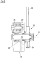
- Fig. 1 shows a designated as a knife or cutting head part of a slicer (slicer) for slicing food products, especially sausage, ham or cheese in a sectional side view.
- a hub 23 is fixed to a housing or a fixed housing wall 31. Inside the hub 23, a combined axial and rotary bearing 21 is arranged for a rotor shaft 13, which defines an axis of rotation 11 of the slicer. The rotor shaft 13 is thus rotatable about the axis of rotation 11 and axially adjustable within the hub 23 in the direction of the axis of rotation 11.
- a not-shown axial drive 71 is provided, which engages the rear end of the rotor shaft 13.
- a rotary drive 33 for the rotor shaft 13 In a located behind the housing wall 31 area is a rotary drive 33 for the rotor shaft 13.
- the rotary drive 33 comprises a provided with an external toothed drive pulley 51 which is mounted in the rear region of the rotor shaft 13 and cooperates with a drive toothed belt 53, which is not a driven drive motor is driven to enable the rotor shaft 13 in rotation about the axis of rotation 11.
- a rotor 15 is fixed. Radially spaced from the axis of rotation 11, the rotor 15 includes a pivot bearing 25 for a blade shaft 35 which defines a blade axis 19 which is parallel to the axis of rotation 11.
- the front, located outside of the rotor 15 end of the cutter shaft 35 is as formed a knife receptacle on which a trained as a circular knife cutting blade 17 is releasably attached.
- the rearwardly projecting end of the blade shaft 35 is formed as a gear 29, which forms a rotor-side part of a rotary drive for the blade shaft 35 and thus for the cutting blade 17.
- a stationary part 27 of this rotary drive is a fixed sprocket, which is supported by the fixed hub 23 or attached to the housing wall 31.
- the annular gear rim 27, which is arranged concentrically to the axis of rotation 11, is provided with an internal toothing which interacts with the external toothing of the toothed wheel 29 of the knife shaft 35.
- the cutting blade 17 thus performs a planetary orbital motion about the axis of rotation 11 and additionally a self-rotation about the knife axis 19 defined by the blade shaft 35.
- the eccentric arrangement of the cutting blade 17 with respect to the axis of rotation 11 of the rotor shaft results in an imbalance UM of the rotor 15.
- this imbalance UM is compensated by a counterweight comprising two balancing masses 47, 49.
- a first balance mass 47 is formed by the rotor 15.
- the first balance mass 47 generates an imbalance U1, that of the imbalance Is at least approximately opposite in the radial direction.
- the second balancing mass 49 is formed by the drive pulley 51 and is at least approximately effective in the same radial direction as the imbalance UM (see also FIG Fig. 5 ).
- the slicing device according to the invention consequently has a simple, compact and extremely hygienic design.
- the housing wall 31 separates the drive area from the cutting area.
- a seal 55 seals the axial and pivot bearing 21 from the environment.
- the axial "nesting" of lying outside the housing wall 31 components provides an extremely compact structure with low axial length: With its rear, located on the housing wall 31 area, the hub 23 is located within the ring gear 27, in which the cutter shaft 35 with the gear 29 engages axially. The hub 23 itself and the rotor 15 also engage axially with each other.
- the pivot bearing 25 for the cutting blade 17 is located axially in the amount of the front portion of the hub 23 and in the amount of the axial and pivot bearing 21st
- the rotor shaft 13 together with the rotor 15 and cutting blade 17 and cutter shaft 35 and gear 29 is adjusted in the axial direction.
- the rotary drive for the cutting blade 17 formed by the fixed ring gear 27 and the gear 29 of the blade shaft 35 allows such axial adjustment movement while maintaining the rotary drive by interaction of ring gear 27 and gear 29.
- this embodiment of the rotary drive allows the rotor 15 together with the cutting blade 17 and blade shaft 35 to be removed simply by loosening the screw connection between the rotor 15 and the front end of the rotor shaft 13, i. can be deducted in the axial direction, can.
- the imbalance U1 of the balancing mass 47 in the rotor 15 and the imbalance UM of the rotor 15 caused by the cutting blade 17 are matched to one another and to the imbalance U2 of the balancing mass 49 integrated in the rotary drive 33.
- the blade holder (not shown) carrying the sickle blade is likewise provided with a balancing mass which is tuned to the respective imbalance of the sickle blade such that, in cooperation with the unbalance integrated in the rotary drive 33 U2 the balancing mass 49 is again given in all levels and statically and dynamically balanced rotating overall system.
- the unbalance U1 of the rotor 15 is located substantially closer to the cutting plane 61 defined by the cutting blade 17 than the unbalance U2 of the rotary drive 33.
- the unbalance U1 of the rotor 15 is also relatively far radially outward. This geometric arrangement of the balancing masses 47, 49 thus makes it possible to use relatively small balancing masses.
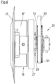
- Fig. 2 shows the slicing device according to the invention without the housing wall 31 and without cutting blade 17. It is again the particular compactness of both radially and axially around the fixed hub 23 around grouping components to recognize.
- Fig. 3 shows the side view of Fig. 3 , in turn, the housing wall 31 is not shown, in particular shows the advantageous under hygienic aspects open design of the located in the cutting area components.
- the rotary bearing for the knife shaft 35 protruding into the sprocket 27 in the rear is provided with a housing 63.
- Fig. 5 shows the strong top-heavy design of the rotor 17 with a relatively heavy portion formed by the first balance mass 47, which is connected via a comparatively light central portion with a diametrically opposite portion, on which the rotary bearing for the blade shaft of the cutting blade 17 is mounted, wherein of the pivot bearing in turn the housing 63 is shown.
- the Fig. 6 and 7 show front views with ( Fig. 6 ) and without ( Fig. 7 ) Cutting knife 17.
- the Fig. 7 in particular, the anchor-like shape of the rotor 15 can be seen.
- the internal toothing of the stationary ring gear 27 is shown.
- FIG. 8 and 9 each show a further embodiment of a slicing device according to the invention, in which for the rotary drive of the circular blade 17 a fixed axis 39 (FIG. Fig. 8 ) or a rotationally driven drive shaft 40 (FIG. Fig. 9 ) is provided.
- the rotor shaft 13 for the rotor 15 is formed as a hollow shaft which carries at a rear portion of a drive pulley 51 which is displaceable via a drive belt 53 by means of a motor not shown in rotation about the rotation axis 11.
- the axis 39 or shaft 40 extends through the hollow shaft 13 and into the rotor 15.
- Fig. 8 carries the axis 39 a likewise fixed with respect to rotation toothed belt wheel 41, on which a rotating toothed belt 43 rotates with a rotating rotor 15, which cooperates with a toothing 45 which is formed on the circular blade 17 bearing blade shaft 35.
- the planetary orbital motion of the blade shaft 35 due to the rotational movement of the rotor 15 relative to the fixed toothed belt wheel 41 is thus used to set the blade shaft 35 and thus the circular blade 17 in rotation about the blade axis 19 relative to the rotor 15.
- the rotor 15 is formed in two parts. This also applies to the embodiment of Fig. 9 ,
- Fig. 8 is the hub 23 together with combined axial and pivot bearing 21 for the rotor shaft designed as a hollow shaft 13 within a housing, that is not open to the outside.
- the hub 23 is fixed to a wall 31 of the housing.
- the rotor shaft 13 is provided with a Anlenkabêt 65 for a turn again only indicated axial drive 71, which serves to axially adjust the rotor shaft 13 together with the rotor 15 and circular blade 17. This is again indicated by double arrows.
- the fixed axis 39 is not axially adjustable as a whole, but telescopically formed, so that the toothed belt 41 bearing front portion of the shaft 39 can be adjusted axially together with the rotor shaft 13, in particular to carry out idle cuts or make a cutting gap setting.
- the hub 23 is formed by a fixed housing wall 31, wherein alternatively, the hub 23 may be formed as a separate component which is fixed to the housing wall 31.
- the drive shaft 40 extending through the rotor shaft 13 designed as a hollow shaft is provided with a toothed belt wheel 67 at its rear end and can be set in rotation by a toothed belt 69 by a separate drive motor, not shown, independently of the rotary drive 33 for the rotor shaft 13.
- the transmission of the rotational movement of the drive shaft 40 to the blade shaft 35 takes place within the rotor 15 via a toothed belt 43 which cooperates with a toothing 45 of the cutter shaft 35 and with a toothed belt wheel 41 of the drive shaft 40.
- a common drive motor be provided with intermediate gear, whereby the belts 53 and 69 are driven.
- a common axial adjustment of the rotor shaft 13 and the drive shaft 40 is effected by an axial drive 71, again not shown, which acts on an articulation section 65 of the rotor shaft 13.
- the above in the introduction part and in connection with the embodiment of Fig. 1 to 7 explained balancing concept is also in the embodiments according to Fig. 8 and Fig. 9 realized:
- the rotor 15 is in each case provided with a first balancing mass 47, while a second balancing mass 49 is respectively integrated into the drive pulley 51 of the rotary drive 33 for the rotor shaft 13 formed here as a hollow shaft.
- the belt drives for the rotor shafts 15 and for the drive shaft 40 of the axial adjustment does not oppose, since in this case only relatively short axial travel are required and consequently the drive belt 53, 69 can be deflected accordingly.
Description
Die Erfindung betrifft eine Vorrichtung zum Aufschneiden von Lebensmittelprodukten, insbesondere Hochleistungs-Slicer. Des Weiteren betrifft die Erfindung ein System mit einer derartigen Aufschneidevorrichtung und mit wenigstens zwei unterschiedlich ausgebildeten Schneidmesserträgern, die jeweils lösbar an einer Rotorwelle anbringbar sind.The invention relates to a device for slicing food products, in particular high-performance slicer. Furthermore, the invention relates to a system with such a slicing device and with at least two differently shaped cutting blade carriers, which are each releasably attachable to a rotor shaft.
Derartige Aufschneidevorrichtungen sind grundsätzlich bekannt und dienen dazu, Lebensmittelprodukte wie beispielsweise Wurst, Fleisch und Käse mit hoher Geschwindigkeit in Scheiben zu schneiden. Typische Schnittgeschwindigkeiten liegen zwischen mehreren 100 bis einigen 1.000 Schnitten pro Minute.Such slicing devices are basically known and serve to slice food products such as sausage, meat and cheese into slices at high speed. Typical cutting speeds are between several hundred to several thousand cuts per minute.
Moderne Hochleistungs-Slicer unterscheiden sich unter anderem in der Ausgestaltung des Schneidmessers sowie in der Art und Weise des Rotationsantriebs für das Schneidmesser. So genannte Sichel- oder Spiralmesser rotieren lediglich um eine Messerachse, wobei diese Messerachse selbst keine zusätzliche Bewegung ausführt. Bei Slicern mit Kreis- oder Orbitalmessern ist dagegen vorgesehen, das um eine Messerachse rotierende Kreismesser zusätzlich zu dieser Eigenrotation um eine von der Messerachse beabstandete weitere Achse - hier als Drehachse bezeichnet - planetarisch umlaufen zu lassen. Welchem Messertyp bzw. welcher Antriebsart der Vorzug zu geben ist, ist von der jeweiligen Anwendung abhängig. Generell lässt sich sagen, dass mit lediglich rotierenden Sichelmessern höhere Schnittgeschwindigkeiten erzielt werden können, wohingegen rotierende und zusätzlich planetarisch umlaufende Kreismesser ohne Einbußen bei der Schneidqualität universeller einsetzbar sind.Modern high-performance slicers differ, inter alia, in the design of the cutting blade and in the manner of the rotary drive for the cutting blade. So-called sickle or spiral blades rotate only about a blade axis, this blade axis itself performs no additional movement. In slicers with circular or orbital knives, on the other hand, it is provided that the circular blade rotating about a knife axis circulate in a planetary manner in addition to this self-rotation about a further axis spaced apart from the knife axis-here called a rotation axis. Which blade type or type of drive is to be preferred depends on the respective application. In general, it can be said that higher cutting speeds can be achieved with only rotating sickle knives, whereas rotating and additionally planetary rotating circular knives can be used more universally without sacrificing cutting quality.
Die Erfindung betrifft Aufschneidevorrichtungen mit einem planetarisch umlaufenden Kreismesser. Typische Schnittgeschwindigkeiten liegen hier im Bereich von etwa 350 bis 800 Umdrehungen pro Minute, d.h. mit einem solchen Slicer können etwa 350 bis 800 Scheiben pro Minute von einem Produkt abgetrennt werden.The invention relates to slicing with a planetary rotating circular blade. Typical cutting speeds here are in the range of about 350 to 800 revolutions per minute, i. With such a slicer, about 350 to 800 slices per minute can be separated from a product.
Etwa ab derartigen Schnittgeschwindigkeiten wird es erforderlich, dass bei einem portionsweisen Aufschneiden von Produkten so genannte Leerschnitte durchgeführt werden, in denen sich das Messer weiterhin bewegt, d.h. seine Schneidbewegung ausführt, dabei jedoch nicht in das Produkt, sondern ins "Leere" schneidet, damit vorübergehend keine Scheiben vom Produkt abgetrennt werden und diese "Schneidpausen" dazu genutzt werden können, eine mit den zuvor abgetrennten Scheiben gebildete Portion, beispielsweise einen Scheibenstapel oder geschindelt angeordnete Scheiben, abzutransportieren. Die zwischen zwei aufeinanderfolgend abgetrennten Scheiben verstreichende Zeit reicht ab einer bestimmten Schneidleistung bzw. Schnittgeschwindigkeit für einen ordnungsgemäße Abtransport der Scheibenportionen nicht mehr aus. Die Länge dieser "Schneidpausen" und die Anzahl der Leerschnitte pro "Schneidpause" sind von der jeweiligen Anwendung abhängig.From about such cutting speeds, it is required that, when slicing products in portions, so-called idle cuts are made in which the knife continues to move, i. performs his cutting motion, but not in the product, but in the "void" cuts, so temporarily no slices are separated from the product and these "cutting breaks" can be used to a formed with the previously separated slices portion, such as a stack of discs or shingles arranged discs to be transported away. The time passing between two consecutively separated slices is no longer sufficient for a proper cutting performance or cutting speed for a proper removal of the slice portions. The length of these "cutting breaks" and the number of idle cuts per "cutting break" depend on the particular application.
Wie bereits erwähnt, wird in der Praxis ein solcher Leerschnittbetrieb ab einer gewissen Grenzschnittgeschwindigkeit oder Grenzdrehzahl des Messers erforderlich, die typischerweise zwischen etwa 350 und 600 Umläufen pro Minute beträgt. Dies ist der Grund dafür, dass moderne Sichelmesser-Slicer, mit denen weitaus höhere Schnittgeschwindigkeiten erzielt werden können, generell mit einem Axialantrieb versehen sind, mit dem das Messer ausreichend schnell vom Produkt wegbewegt werden kann, um Leerschnitte auszuführen. Man spricht in diesem Zusammenhang auch von einem "Wegtakten" des Messers bzw. der das Messer tragenden Messeraufnahme, und derartige Slicer werden auch als "taktbare" Slicer bezeichnet.As already mentioned, in practice, such a blank cut operation is required beyond a certain cut edge speed or knife limit speed, which is typically between about 350 and 600 revolutions per minute. This is why modern sickle knife slicers, which can achieve much higher cutting speeds, are generally provided with an axial drive that allows the knife to be moved away from the product fast enough to make idle cuts. In this context, one also speaks of a "displacement action" of the knife or of the blade-carrying knife receptacle, and such slicers are also referred to as "tactile" slicers.
Obwohl moderne Kreismesser-Slicer - wie erwähnt - meist in einem Drehzahlbereich arbeiten, in welchem ein Wegtakten des Messers zur Durchführung von Leerschnitten zumindest für die meisten Anwendungen nicht zwingend erforderlich ist, wurden derartige taktbare Kreismesser-Slicer bereits vorgeschlagen. Eine Möglichkeit, einen solchen taktbaren Kreismesser-Slicer zu realisieren, ist in
Dieser bekannte Kreismesser-Slicer offenbart ein generelles Grundproblem, welches einer taktbaren Ausgestaltung eines Kreismesser-Slicers prinzipiell entgegensteht, nämlich das Erfordernis, das Kreismesser nicht nur planetarisch umlaufen zu lassen, sondern außerdem mit einer Eigenrotation zu versehen. Das Kreismesser muss folglich nicht nur planetarisch umlaufend angetrieben, sondern außerdem in Rotation um die eigene Messerachse versetzt werden. Hieraus resultiert eine ohnehin schon komplexe Antriebstechnik, die einen ungleich höheren konstruktiven Aufwand erfordert, wenn zusätzlich das Kreismesser schnell und präzise axial verstellt werden soll, um Leerschnitte durchführen zu können.This known circular knife slicer discloses a general basic problem, which in principle precludes a tactile design of a circular blade slicer, namely the requirement not only to circulate the circular blade planetary, but also to provide a self-rotation. Consequently, the circular blade not only has to be driven in a planetary orbit, but also has to be set in rotation around its own knife axis. This results in an already complex drive technology, which requires a much higher design effort, if in addition the circular blade should be adjusted quickly and precisely axially in order to perform idle cuts can.
Die Anforderungen an eine axiale Verstellbarkeit bei Kreismesser-Slicern werden darüber hinaus noch weiter dadurch erhöht, dass Kreismesser - anders als Sichelmesser - auf einem anderen Schneidprinzip basieren: Während bei Sichelmessern die für das Schneiden erforderliche Relativbewegung zwischen Messerschneide und Produkt durch die Sichel- oder Spiralform des lediglich um die Messerachse rotierenden Messers erzeugt wird, ist es bei Kreismessern die planetarische Umlaufbewegung, welche die erforderliche Schneidebewegung erzeugt. Dies hat zur Folge, dass bei Kreismessern im Vergleich zu Sichelmessern pro Umlauf mehr Zeit zur Verfügung steht, in welcher sich das Messer außerhalb des Produktbereiches befindet und somit axial verstellt werden kann. Bei Kreismessern beträgt der entsprechende Drehwinkelbereich, der auch als Freiwinkel bezeichnet wird, oft mehr als 180°, wohingegen bei Sichelmessern, die zudem mit einer höheren Drehzahl betrieben werden, nur ein Freiwinkel von typischerweise knapp 100° zu Verfügung steht.The requirements for axial adjustability in circular knife slicers are further increased by the fact that circular knives - unlike sickle knives - are based on a different cutting principle: While in sickle knives the relative movement between knife edge and product required for cutting by the sickle or spiral shape of the knife rotating only around the knife axis, in circular knives it is the planetary orbital motion which produces the required cutting motion. This has the consequence that in circular knives compared to sickle blades per round more time is available, in which the knife outside the product range is located and thus can be adjusted axially. For circular knives, the corresponding rotation angle range, which is also referred to as clearance angle, often more than 180 °, whereas in sickle blades, which are also operated at a higher speed, only a clearance angle of typically just under 100 ° is available.
Kreismesser-Slicer sind folglich, was eine Axialverstellung angeht, im Prinzip insgesamt deutlich weniger zeitkritisch. Gleichwohl ist bislang kaum versucht worden, für die Praxis taugliche Konzepte für taktbare Kreismesser-Slicer zu entwickeln.Circular knife slicers are thus, in principle, significantly less time-critical in terms of axial adjustment. However, so far has hardly been trying to develop practical concepts for tactile circular knife slicer.
Ergänzend sei auf
Aufgabe der Erfindung ist es, eine Aufschneidevorrichtung zu schaffen, die auf dem Prinzip eines planetarisch umlaufenden Kreismessers beruht und zu einem Leerschnittbetrieb in der Lage ist, wobei außerdem ein einfacher, kompakter und hygienischer Aufbau sowie insbesondere die volle Funktionalität moderner Hochleistungs-Slicer gegeben sein soll.The object of the invention is to provide a slicing device, which is based on the principle of a planetary rotating circular knife and is capable of a blank cutting operation, which also should be given a simple, compact and hygienic design and in particular the full functionality of modern high-performance slicer ,
Die Lösung dieser Aufgabe erfolgt durch die Merkmale der Ansprüche 1 und 15.The solution of this object is achieved by the features of
Erfindungsgemäß umfasst die Aufschneidevorrichtung eine im Betrieb um eine Drehachse rotierende und axial verstellbare Rotorwelle, einen von der Rotorwelle angetriebenen Rotor, ein vom Rotor getragenes Schneidmesser, das um die Drehachse planetarisch umläuft und zusätzlich relativ zum Rotor um eine parallel versetzt zur Drehachse verlaufende Messerachse rotiert, und einen Rotationsantrieb für die Rotorwelle.According to the invention, the slicing device comprises a rotor shaft which rotates about an axis of rotation and is axially adjustable during operation, a rotor driven by the rotor shaft, a rotor carried by the cutting blade which rotates planetary about the axis of rotation and additionally rotates relative to the rotor about a knife axis parallel to the rotation axis, and a rotary drive for the rotor shaft.
Die Erfindung basiert auf dem Gedanken, in Abkehr von dem vorstehend erläuterten Konzept gemäß
Dieses Konzept ermöglicht - vor allem bei bestimmten konkreten Ausgestaltungen, wie sie nachstehend näher erläutert werden - in überraschender Weise einen einfachen, geradezu minimalistischen Aufbau eines taktbaren Kreismesser-Slicers, der zudem kompakt ist, höchsten Anforderungen an die Hygiene entspricht und darüber hinaus - trotz Weglassens von an anderen Hochleistungs-Slicern mit vergleichbarer Leistungsfähigkeit vorhandenen Komponenten - gleichwohl ein sehr hohes Maß an Funktionalität erfüllt. Das erfindungsgemäß Konzept ermöglicht auch und gerade eine Konzentration auf eine optimale Axialverstellung des Messers, wodurch wichtige Funktionen wie z.B. die Schneidspalteinstellung mit übernommen werden können, so dass z.B. keine axial verstellbare Schneidkante benötigt wird. Auch ein Zurückziehen des Produktes ist nicht erforderlich, da für einen Leerschnittbetrieb das Messer axial verstellt werden kann. Schließlich können aus diesem Grund auch aufwendige Traktoren bzw. Förderbänder für das Produkt weggelassen werden.This concept allows - especially in certain specific embodiments, as explained in more detail below - surprisingly a simple, almost minimalist construction of a tactile circular knife Slicers, which is also compact, meets the highest standards of hygiene and beyond - despite omission from other high-performance slicers with comparable performance, yet fulfilling a very high level of functionality. The concept according to the invention also and precisely allows a concentration on an optimal axial displacement of the blade, whereby important functions such as e.g. the cutting gap setting can be taken over, so that e.g. no axially adjustable cutting edge is needed. It is also not necessary to retract the product since the blade can be adjusted axially for a blank cutting operation. Finally, for this reason, even expensive tractors or conveyor belts for the product can be omitted.
Mit anderen Worten ist eine Besonderheit der Erfindung, dass ein Kreismesser-Slicer, der aufgrund der Schnittgeschwindigkeit eigentlich keine Messeraxialverstellung benötigt, gleichwohl hinsichtlich einer Messeraxialverstellung optimiert wird, da erkannt wurde, dass bei geschicktem Grundaufbau auch ein Kreismesser-Slicer mit einer schnell und zuverlässig funktionierenden Axialverstellung für das Messer versehen werden und diese Axialverstellung zudem wesentliche Funktionen mit übernehmen kann, wodurch wiederum ansonsten notwendige Komponenten weggelassen werden können, was - und so schließt sich der Kreis - die Optimierung der Axialverstellung zumindest erleichtert.In other words, a peculiarity of the invention is that a circular blade slicer, which actually requires no Messeraxialverstellung due to the cutting speed, is nevertheless optimized with respect to a Messeraxialverstellung, since it was recognized that clever basic design and a circular blade slicer with a fast and reliable functioning Axial adjustment for the knife are provided and these axial adjustment can also take over essential functions, which in turn can be omitted otherwise necessary components, which - and so closes the circle - the optimization of the axial adjustment at least facilitated.
Mögliche Ausgestaltungen der erfindungsgemäßen Aufschneidevorrichtung sind in den abhängigen Ansprüchen, der Beschreibung sowie der Zeichnung angegeben.Possible embodiments of the slicing device according to the invention are specified in the dependent claims, the description and the drawings.
In einem Ausführungsbeispiel ist ein kombiniertes Axial- und Drehlager für die Rotorwelle vorgesehen, relativ zu welchem die Rotorwelle drehbar ist und axial verstellt werden kann. Dabei kann insbesondere das Axial- und Drehlager eine feststehende Nabe umfassen oder einer feststehenden Nabe zugeordnet sein. Die Nabe kann folglich einen Bestandteil des Axial- und Drehlagers bilden oder als ein mit dem Axial- und Drehlager zusammenwirkendes Bauteil angesehen werden. Ein derartiges kombiniertes Lager für die Drehbewegung der Rotorwelle einerseits und die Axialbewegung der Rotorwelle andererseits ermöglicht einen einfachen und kompakten Aufbau.In one embodiment, a combined axial and rotary bearing for the rotor shaft is provided, relative to which the rotor shaft is rotatable and can be adjusted axially. In particular, the axial and rotary bearings may comprise a fixed hub or be associated with a fixed hub. The hub can thus form part of the axial and pivot bearing or be considered as a cooperating with the axial and pivot bearing component. Such a combined bearing for the rotational movement of the rotor shaft on the one hand and the axial movement of the rotor shaft on the other hand allows a simple and compact structure.
Wenn eine feststehende Nabe für das Axial- und Drehlager vorgesehen ist, dann kann diese Nabe für eine Mehrzahl von Funktionen genutzt werden. Mittels der Nabe kann die Rotorwelle an einem feststehenden Gestell- oder Rahmenteil, beispielsweise einer Gehäusewand, der Vorrichtung abgestützt werden. Alternativ oder zusätzlich kann die Nabe als Stütze für wietere Komponenten dienen, beispielsweise für Komponenten, die mit einem Drehantrieb für die Eigenrotation des Schneidmessers zusammenwirken oder einen stationären Teil eines solchen Drehantriebs bilden.If a fixed hub for the thrust and pivot bearing is provided, then this hub can be used for a plurality of functions. By means of the hub, the rotor shaft can be supported on a fixed frame or frame part, for example a housing wall, of the device. Alternatively or additionally, the hub can serve as a support for other components, for example for components which cooperate with a rotary drive for the self-rotation of the cutting blade or form a stationary part of such a rotary drive.
Eine besonders kompakte, insbesondere in axialer Richtung vergleichsweise kurz bauende Anordnung kann erzielt werden, wenn gemäß einem weiteren Ausführungsbeispiel ein vorderer Bereich einer Nabe für die Rotorwelle und zumindest ein ein Drehlager für das Schneidmesser umfassender Bereich des Rotors axial ineinander greifen, und wenn außerdem ein am hinteren Bereich der Nabe angeordneter stationärer Teil eines Drehantriebs für das Schneidmesser und ein rotorseitiger Teil des Drehantriebs axial ineinander greifen.A particularly compact, in particular in the axial direction comparatively short construction arrangement can be achieved if, according to another embodiment, a front portion of a hub for the rotor shaft and at least one rotary bearing for the cutting blade comprehensive range of the rotor axially engage, and if also a on rear part of the hub arranged stationary part of a rotary drive for the cutting blade and a rotor-side part of the rotary drive axially engage with each other.
Hierbei wird der Umstand ausgenutzt, dass die die Drehachse für den Rotor bereitstellende Rotorwelle und der die Messerachse für die Eigenrotation des Messers definierende Drehantrieb radial beabstandet sind. Diese Anordnung ermöglicht folglich das jeweilige axiale Ineinandergreifen der Bauteile und sorgt insgesamt für einen gewissermaßen "verschachtelten" Aufbau bzw. eine hohe Packungsdichte der betreffenden Komponenten. Der zur Verfügung stehende Bauraum insbesondere in axialer Richtung wird hierdurch optimal genutzt. Die relativ kurze Baulänge einer derartigen Konstruktion verringert außerdem die erforderlichen Stützkräfte, die insbesondere von der Nabe aufgenommen werden müssen.In this case, the fact is utilized that the rotary shaft providing the rotor shaft and the blade axis defining the blade for the self-rotation of the rotary drive are radially spaced. This arrangement thus enables the respective axial engagement of the components and overall provides for a somewhat "nested" structure or a high packing density of the respective components. The available space, especially in the axial direction is thereby used optimally. The relatively short length of such a construction also reduces the required supporting forces, which in particular must be absorbed by the hub.
Wie bereits erwähnt, kann eine für die Rotorwelle vorgesehene Nabe, die für die Axial- und Drehlagerung der Rotorwelle sorgt, von einem feststehenden Gestell- oder Rahmenteil der Vorrichtung getragen sein.As already mentioned, a hub provided for the rotor shaft, which ensures the axial and rotational mounting of the rotor shaft, can be carried by a fixed frame or frame part of the device.
Insbesondere unter hygienischen Gesichtspunkten besonders vorteilhaft ist eine bevorzugte Anordnung, wonach eine Nabe für die Rotorwelle nach außen offen liegt und ein kombiniertes Axial- und Drehlager für die Rotorwelle zwischen der Nabe und der Rotorwelle gegenüber der Umgebung abgedichtet ist.Particularly advantageous from a hygienic point of view is a preferred arrangement, according to which a hub for the rotor shaft is exposed to the outside and a combined axial and rotary bearing for the rotor shaft between the hub and the rotor shaft is sealed from the environment.
Die Rotorwelle ist insbesondere durch ein feststehendes Gestell- oder Rahmenteil hindurchgeführt, auf dessen einer Seite der Rotationsantrieb und auf dessen anderer Seite der Rotor angeordnet ist. Hierdurch wird mittels des insbesondere als Gehäuse oder Gehäusewand ausgebildeten Gestell- oder Rahmenteils der Antriebsbereich der Rotorwelle vom Schneidebereich getrennt, was insbesondere unter hygienischen Gesichtspunkten vorteilhaft ist.The rotor shaft is in particular passed through a fixed frame or frame part, on one side of the rotary drive and on the other side of the rotor is arranged. As a result, the drive region of the rotor shaft is separated from the cutting region by means of the frame or frame part designed in particular as a housing or housing wall, which is advantageous in particular from a hygienic point of view.
In einem besonders vorteilhaften Ausführungsbeispiel der Erfindung ist ein für die Eigenrotation des Schneidmessers sorgender Drehantrieb von der Rotorwelle entkoppelt. Hierdurch ist es nicht erforderlich, den Drehantrieb für das Messer unmittelbar durch die Rotorwelle zu bewirken. Deshalb ist es möglich, konstruktiv aufwendige Riemen- oder Zahnradanordnungen zu vermeiden, die anderenfalls vorgesehen sein müssten, um den Drehantrieb für die Eigenrotation des Messers unmittelbar durch die Rotorwelle bereitzustellen.In a particularly advantageous exemplary embodiment of the invention, a rotary drive which is responsible for the self-rotation of the cutting blade is decoupled from the rotor shaft. As a result, it is not necessary to effect the rotary drive for the knife directly through the rotor shaft. Therefore It is possible to avoid structurally complex belt or gear arrangements, which would otherwise have to be provided to provide the rotary drive for the self-rotation of the knife directly through the rotor shaft.
Besonders bevorzugt ist es, wenn der Drehantrieb für das Schneidmesser von der Drehbewegung des Rotors abgeleitet wird.It is particularly preferred if the rotary drive for the cutting blade is derived from the rotational movement of the rotor.
Die ohnehin erfolgende Umlaufbewegung des Rotors kann so dazu benutzt werden, das aufgrund der Drehbewegung des Rotors planetarisch umlaufende Messer zusätzlich relativ zum Rotor in eine Eigenrotation zu versetzen. Mit anderen Worten kann die aufgrund des planetarischen Umlaufs des Kreismessers gegebene Relativbewegung des Messers, insbesondere einer mit dem Messer lösbar verbundenen Messerwelle, ausgenutzt werden, um dem Messer bzw. der Messerwelle eine Eigenrotation zu verleihen.The rotational movement of the rotor, which in any case takes place, can thus be used to additionally set the blade, which rotates planetaryly due to the rotational movement of the rotor, into a self-rotation relative to the rotor. In other words, given due to the planetary rotation of the circular blade relative movement of the knife, in particular a blade detachably connected to the knife shaft can be exploited to give the knife or the knife shaft a self-rotation.
In einem Ausführungsbeispiel kann der Drehantrieb für das Schneidmesser einen stationären Teil und einen rotorseitigen Teil umfassen, wobei der stationäre Teil und der rotorseitige Teil bei an der Rotorwelle angebrachtem Rotor zusammenwirken. Die aufgrund des planetarischen Umlaufs gegebene Relativbewegung des rotorseitigen Teils des Drehantriebs bezüglich des stationären Teils kann hierdurch in eine Drehbewegung des rotorseitigen Teils und somit des Messers bzw. der Messerwelle umgesetzt werden.In one embodiment, the rotary drive for the cutting blade may comprise a stationary part and a rotor-side part, wherein the stationary part and the rotor-side part cooperate with the rotor mounted on the rotor shaft. The given due to the planetary circulation relative movement of the rotor-side part of the rotary drive with respect to the stationary part can thereby be converted into a rotational movement of the rotor-side part and thus the blade or the blade shaft.
Das Zusammenwirken zwischen dem stationären Teil und dem rotorseitigen Teil ist insbesondere derart ausgestaltet, dass Relativbewegungen in axialer Richtung zwischen den beiden Teilen zugelassen sind. Hierdurch ist es möglich, insbesondere für die Durchführung von Leerschnitten und/oder zur Schneidspalteinstellung und/oder zur Montage oder Demontage des Rotors, die Rotorwelle samt Messer und rotorseitigem Teil des Drehantriebs axial zu verstellen, ohne dass der Drehantrieb dem entgegenstehen würde.The interaction between the stationary part and the rotor-side part is in particular designed such that relative movements in the axial direction between the two parts are permitted. This makes it possible, in particular for the implementation of blank sections and / or for cutting gap adjustment and / or assembly or disassembly of the rotor, the rotor shaft together with knife and rotorseitigem part to adjust the rotary drive axially, without the rotary drive would oppose.
Hierbei ist insbesondere vorgesehen, dass die Rotorwelle relativ zu dem stationären Teil des Drehantriebs für das Schneidmesser axial verstellbar ist.In this case, provision is made in particular for the rotor shaft to be axially adjustable relative to the stationary part of the rotary drive for the cutting blade.
Der stationäre Teil des Drehantriebs für das Schneidmesser kann von einem kombinierten Axial- und Drehlager und/oder von einer Nabe für die Rotorwelle getragen sein. Auf diese Weise kann die Nabe zur Eigenrotation des Schneidmessers beitragen.The stationary part of the rotary drive for the cutting blade may be carried by a combined axial and rotary bearings and / or by a hub for the rotor shaft. In this way, the hub can contribute to the self-rotation of the cutting blade.
Ein rotorseitiger Teil des Drehantriebs, der zusammen mit dem Rotor die Drehbewegung ausführt, kann von einer Messerwelle des Schneidmessers gebildet sein, so dass es die Messerwelle ist, die mit dem stationären Teil des Drehantriebs zusammenwirkt.A rotor-side part of the rotary drive, which carries out the rotary movement together with the rotor, may be formed by a blade shaft of the cutting blade, so that it is the blade shaft, which cooperates with the stationary part of the rotary drive.
Der stationäre Teil des Drehantriebs kann einen Ring umfassen, an welchem die Messerwelle abrollt. Dabei ist insbesondere vorgesehen, dass der Ring als Zahnkranz ausgebildet ist, der mit einem Zahnrad der Messerwelle zusammenwirkt.The stationary part of the rotary drive may comprise a ring on which the blade shaft rolls. It is particularly provided that the ring is designed as a toothed ring, which cooperates with a gear of the knife shaft.
Dieses Konzept zur Realisierung des Drehantriebs für die Eigenrotation des Messers ist konstruktiv einfach und zuverlässig, wobei außerdem der zur Verfügung stehende Bauraum optimal ausgenutzt wird, ohne dass eine komplizierte Mechanik zur Übertragung der Rotationsbewegung der Rotorwelle in radialer Richtung nach außen auf die Messerwelle erforderlich wäre. Komplexe Riemen- oder Zahnradanordnungen werden hierdurch vermieden.This concept for the realization of the rotary drive for the self-rotation of the blade is structurally simple and reliable, wherein also the available space is optimally utilized without a complicated mechanism for transmitting the rotational movement of the rotor shaft in the radial direction would be required outwardly on the blade shaft. Complex belt or gear arrangements are thereby avoided.
In einer alternativen Ausgestaltung des Drehantriebs für die Eigenrotation des Drehmessers ist gemäß einem weiteren Ausführungsbeispiel der Erfindung eine koaxial zur Rotorwelle angeordnete Antriebswelle oder Antriebsachse vorgesehen, mit der eine Messerwelle des Schneidmessers antreibbar ist, beispielsweise über eine Riemen- und/oder Zahnradanordnung. Dabei ist es möglich, aber nicht zwingend, dass für die Antriebswelle ein separater Drehantrieb vorgesehen wird. Bei der Achse kann es sich um eine feststehende, d.h. nicht rotierende, Antriebsachse handeln, relativ zu welcher sich der Rotor dreht, wobei diese Relativbewegung in die Eigenrotation des Messers bzw. der Messerwelle umgesetzt wird.In an alternative embodiment of the rotary drive for the self-rotation of the rotary blade according to a further embodiment of the invention is a coaxial with the rotor shaft arranged drive shaft or drive axle provided, with a blade shaft of the cutting blade is driven, for example via a belt and / or gear arrangement. It is possible, but not mandatory, for the drive shaft, a separate rotary drive is provided. The axis can be a fixed, ie non-rotating, drive axis relative to which the rotor rotates, this relative movement being converted into the intrinsic rotation of the blade or of the blade shaft.
Die Antriebswelle oder die Antriebsachse kann teleskopierbar ausgebildet sein, um auf diese Weise eine Axialverstellung insbesondere zur Durchführung von Leerschnitten und/oder zur Schneidspalteinstellung zu ermöglichen. Alternativ kann die Antriebswelle bzw. die Antriebsachse als Ganzes axial verstellbar sein.The drive shaft or the drive shaft may be telescopic, in order to allow in this way an axial adjustment, in particular for performing blank cuts and / or for cutting gap adjustment. Alternatively, the drive shaft or the drive axle as a whole can be axially adjustable.
Bei einer besonders vorteilhaften Ausgestaltung ist die Rotorwelle als eine Hohlwelle ausgebildet, durch welche sich die Antriebswelle oder die Antriebsachse hindurch erstreckt.In a particularly advantageous embodiment, the rotor shaft is designed as a hollow shaft through which the drive shaft or the drive axle extends.
Das Zusammenwirken zwischen der Antriebswelle oder Antriebsachse für die Eigenrotation des Schneidmessers mit der Messerwelle kann in einem weiteren Ausführungsbeispiel innerhalb des Rotors erfolgen, wobei sich die Antriebswelle oder Antriebsachse in den Rotor hinein erstreckt.The interaction between the drive shaft or drive shaft for the self-rotation of the cutting blade with the blade shaft can be carried out within the rotor in a further embodiment, wherein the drive shaft or drive shaft extends into the rotor.
Insbesondere für die Durchführung von Leerschnitten und/oder zur Schneidspalteinstellung ist bevorzugt vorgesehen, dass sowohl die Rotorwelle als auch die Antriebswelle oder Antriebsachse zumindest teilweise axial verstellbar sind. Insbesondere sind die Rotorwelle und die Antriebswelle oder Antriebsachse gleichzeitig oder gemeinsam axial verstellbar.In particular, for the implementation of empty cuts and / or for cutting gap adjustment is preferably provided that both the rotor shaft and the drive shaft or drive shaft are at least partially axially adjustable. In particular, the rotor shaft and the drive shaft or drive axle are simultaneously or jointly axially adjustable.
Bei einer Aufschneidevorrichtung mit planetarisch umlaufendem Schneidmesser ist das Schneidmesser gegenüber der den Rotor in Drehung versetzenden Rotorwelle und somit gegenüber der Drehachse des Rotors radial nach außen versetzt, d.h. das Schneidmesser ist exzentrisch angeordnet. Hierdurch weist der Rotor eine durch das Schneidmesser bedingte Unwucht auf. Um insbesondere bei den hohen Drehzahlen im Schneidebetrieb einen vibrationsfreien Lauf des Rotors bzw. des Messers zu gewährleisten, muss die Aufschneidevorrichtung in allen Ebenen ausgewuchtet sein.In a slicing device with a planetary rotating cutting blade, the cutting blade is offset radially outwards relative to the rotor shaft which sets the rotor in rotation and thus with respect to the axis of rotation of the rotor, ie the cutting blade is arranged eccentrically. As a result, the rotor has an imbalance caused by the cutting blade. In order to ensure a vibration-free running of the rotor or the knife, especially at the high speeds in the cutting operation, the slicing must be balanced in all planes.
Die erfindungsgemäße Aufschneidevorrichtung, insbesondere bei einer Ausgestaltung, wie sie vorstehend anhand möglicher Ausführungsformen erläutert wurde, ermöglicht ein besonders einfaches und wirkungsvolles Wuchtkonzept, das den erwähnten Anforderungen genügt. Im Unterschied zu bekannten Wuchtkonzepten kommt die Erfindung insbesondere ohne komplexe Konstruktionen und ohne teure Materialien wie z.B. Wolfram für die Wuchtmassen aus.The slicing device according to the invention, in particular in one embodiment, as has been explained above with reference to possible embodiments, enables a particularly simple and effective balancing concept which satisfies the mentioned requirements. In contrast to known balancing concepts, the invention in particular comes without complex constructions and without expensive materials such as e.g. Tungsten for the balancing masses out.
Unter dem Begriff "Unwucht" ist im Folgenden auch allgemein je nach Zusammenhang eine Unwuchtmasse, eine Unwuchtlage und/oder eine bei der Rotation aufgrund der Unwuchtmasse wirksame Kraft hinsichtlich Betrag und Richtung zu verstehen.The term "imbalance" in the following also generally depending on the context of an imbalance mass, an imbalance position and / or effective in the rotation due to the imbalance mass force in terms of magnitude and direction to understand.
Axiale Abstände, also längs der Drehachse bzw. der Messerachse gemessene Abstände, relativ zu einem Schneidmesser beziehen sich hier, sofern nichts anderes angegeben ist, auf eine durch das Messer bzw. die Messerschneide definierte Schneidebene, während sich die axiale Lage einer Wuchtmasse bzw. Unwucht auf eine Ebene bezieht, die senkrecht zur Drehachse bzw. Messerachse verläuft und in welcher der Massenschwerpunkt der Wuchtmasse bzw. Unwucht liegt. Generell beziehen sich hier Angaben zur Lage oder Wirkungsrichtung einer Wuchtmasse, sofern nichts anderes angegeben ist, auch auf die durch die Wuchtmasse bzw. durch die Komponente oder Baugruppe, in welche die betreffende Wuchtmasse integriert ist, erzeugte Unwucht.Axial distances, that is, along the axis of rotation or the knife axis measured distances relative to a cutting blade relate here, unless otherwise stated, to a defined by the blade or the cutting edge cutting plane, while the axial position of a balancing mass or imbalance refers to a plane which is perpendicular to the axis of rotation or knife axis and in which the center of mass of the balancing mass or imbalance. In general, here statements relating to the position or direction of action of a balancing mass, unless stated otherwise, also refer to the unbalance produced by the balancing mass or by the component or assembly in which the balancing mass in question is integrated.
Wenn eine Integration einer Wuchtmasse in eine Komponente oder Baugruppe der Vorrichtung im Sinne eines gezielten Hinzufügens einer zusätzlichen Masse verstanden wird, dann ist für den Fachmann klar, dass dies gleichbedeutend ist mit einer gezielten Wegnahme von Material von einer Komponente oder Baugruppe, mathematisch gesprochen also mit einem gezielten Hinzufügen einer "negativen Wuchtmasse", allgemein also mit der gezielten Erzeugung einer Unwucht an oder in der betreffenden Komponente bzw. Baugruppe.If an integration of a balancing mass in a component or assembly of the device in the sense of a targeted addition of an additional Mass is understood, then it is clear to those skilled in the art that this is synonymous with a targeted removal of material from a component or assembly, mathematically speaking with a targeted addition of a "negative balancing mass", in general so with the targeted generation of an imbalance or in the relevant component or module.
Gemäß einem Ausführungsbeispiel der Erfindung sind zum Ausgleichen einer durch das Schneidmesser hervorgerufenen Unwucht des Rotors wenigstens zwei Wuchtmassen vorgesehen, wobei alle Wuchtmassen auf der der Demontageseite des Schneidmessers gegenüberliegenden Seite des Schneidmessers angeordnet und vorzugsweise axial voneinander beabstandet sind.According to one exemplary embodiment of the invention, at least two balancing masses are provided for compensating for an imbalance of the rotor caused by the cutting blade, all balancing masses being arranged on the side of the cutting blade opposite the dismounting side of the cutting blade and preferably axially spaced from one another.
Dies bedeutet eine Abkehr von solchen bekannten Wuchtkonzepten, bei denen das Gegengewicht zum Ausgleichen der Unwucht auf beide Messerseiten aufgeteilt, also zumindest eine Wuchtmasse vor und wenigstens eine weitere Wuchtmasse hinter dem Messer angeordnet ist. Zudem ermöglicht es dieses Konzept, ohne komplexe Konstruktionen und ohne teure Materialien für die Wuchtmassen auszukommen.This means a departure from such known balancing concepts in which the counterweight for balancing the unbalance divided on both sides of the knife, so at least one balancing mass before and at least one further balancing mass is arranged behind the knife. In addition, this concept makes it possible to manage without complex constructions and without expensive materials for the balancing masses.
In einem vorteilhaften Ausführungsbeispiel der Erfindung bildet der Rotor eine Wuchtmasse und weist der Rotor bezüglich der Drehachse eine asymmetrische Rotationsgeometrie auf.In an advantageous embodiment of the invention, the rotor forms a balancing mass and the rotor has an asymmetrical rotational geometry with respect to the axis of rotation.
Hierbei ist es der Rotor selbst, der eine zum Auswuchten des Messers dienende Wuchtmasse bildet, d.h. der Rotor selbst gleicht seine durch das exzentrisch angeordnete Messer bedingte Unwucht zumindest teilweise aus. Hierdurch wird es ermöglicht, die benötigte Wuchtmasse einerseits axial nahe am Messer und andererseits radial relativ weit außen zu positionieren. Hierdurch wird insgesamt ein besonders effizientes Wuchtkonzept realisierbar. Durch die asymmetrische Ausbildung des Rotors kann bei relativ geringem Gesamtgewicht des Rotors eine ausreichend große Unwucht erzeugt werden.In this case, it is the rotor itself which forms a balancing mass serving for balancing the blade, ie the rotor itself at least partially compensates for its imbalance caused by the eccentrically arranged blade. This makes it possible to position the required balancing mass on the one hand axially close to the knife and on the other hand radially relatively far outward. As a result, a particularly efficient balancing concept can be realized overall. Due to the asymmetric design of the rotor can At a relatively low total weight of the rotor, a sufficiently large imbalance can be generated.
Insbesondere zugunsten einer möglichst weit radial außen liegenden Wuchtmasse kann der Rotor von einer kreisförmigen Außenkontur extrem abweichen und gewissermaßen stark kopflastig - bezogen auf die radiale Richtung - ausgebildet werden, d.h. mit einer relativ großen Unwucht bzw. Unwuchtmasse behaftet sein, beispielsweise - bildlich gesprochen - wie ein rotierender Hammer.In particular, in favor of as far as possible radially outward balancing mass, the rotor can deviate extremely from a circular outer contour and, to a certain extent, highly top-heavy - with respect to the radial direction - be formed, i. be associated with a relatively large unbalance or imbalance mass, for example - figuratively speaking - like a rotating hammer.
Indem der Rotor selbst eine Wuchtmasse bildet, gestaltet sich die Konstruktion besonders einfach. Die Wuchtmasse befindet sich außerdem auf diese Weise axial besonders nahe an der Schneidebene. Eine weitere, separate Wuchtmasse in axialer Nähe des Schneidmessers ist somit nicht notwendig.By the rotor itself forms a balancing mass, the construction is particularly simple. The balancing mass is also in this way axially particularly close to the cutting plane. Another, separate balancing mass in the axial vicinity of the cutting blade is therefore not necessary.
Bei einem Austausch eines Messers durch ein Messer mit einem anderen Gewicht, womit folglich eine andere Unwucht hervorgerufen wird, braucht lediglich der Rotor ausgetauscht zu werden. Die Aufschneidevorrichtung ist somit besonders einfach an verschiedene Anwendungen anpassbar. Auf einfache Weise können dadurch Messer mit unterschiedlichem Gewicht eingesetzt werden.When replacing a knife by a knife with a different weight, thus resulting in a different imbalance, only the rotor needs to be replaced. The slicing device is thus particularly easy to adapt to various applications. This makes it easy to use different weight knives.
Dadurch, dass lediglich der Rotor ausgetauscht werden muss, können die weiteren Komponenten der Aufschneidevorrichtung beibehalten werden. Insbesondere kann eine zusätzlich vorgesehene weitere Wuchtmasse in derselben Position verbleiben.The fact that only the rotor needs to be replaced, the other components of the slicer can be maintained. In particular, an additionally provided further balancing mass can remain in the same position.
Gemäß einem Ausführungsbeispiel der Erfindung kann eine weitere Wuchtmasse von dem Rotationsantrieb gebildet werden, insbesondere von einer Antriebsscheibe oder von einer Nabe, die mittels eines Antriebsmotors über einen Antriebsriemen in Rotation versetzbar ist. Hierdurch erfüllt der Rotationsantrieb eine weitere Funktion, indem nicht nur die Rotorwelle in Rotation versetzt wird, sondern außerdem ein Teil der Unwucht des Rotors ausgeglichen wird.According to one embodiment of the invention, a further balancing mass can be formed by the rotary drive, in particular by a drive pulley or by a hub which can be set in rotation by means of a drive motor via a drive belt. As a result, the rotary drive performs another function by not only the rotor shaft is set in rotation, but also a part of the imbalance of the rotor is compensated.
Folglich bildet der Rotationsantrieb aufgrund der Wuchtmasse bzw. der Unwucht zusammen mit dem Rotor samt Kreismesser ein Massensystem, das derart hinsichtlich Dimensionierung und Anordnung ausgelegt werden kann, dass sich der Gesamtschwerpunkt des rotierenden Systems auf derjenigen Seite des Schneidmessers befindet, auf der auch der Rotationsantrieb gelegen ist. Mit anderen Worten wird dieser Schwerpunkt durch die Unwucht im Rotationsantrieb auf dessen Seite "gezogen". Folglich ist es möglich, die weitere Wuchtmasse ebenfalls auf dieser Seite des Schneidmessers anzuordnen, so dass sich alle Wuchtmassen nur auf einer Seite des Schneidmessers befinden.Consequently, the rotational drive forms due to the balancing mass or unbalance together with the rotor and circular blade a mass system that can be designed in terms of dimensioning and arrangement such that the overall center of gravity of the rotating system is located on that side of the cutting blade on which also the rotary drive located is. In other words, this focus is "pulled" by the imbalance in the rotary drive on its side. Consequently, it is possible to arrange the further balancing mass also on this side of the cutting blade, so that all balancing masses are only on one side of the cutting blade.
Bezogen auf die axiale Länge der Gesamtanordnung - gemessen zwischen Schneidebene und Ebene des Rotationsantriebs - kann die Wuchtmasse des Rotationsantriebs in relativ großer axialer Entfernung von der Schneidebene angeordnet werden. Hieraus resultiert gewissermaßen eine relativ große Hebelwirkung dieser Wuchtmasse, die damit selbst nur ein vergleichsweise geringes Gewicht aufzuweisen braucht, was wiederum in der Praxis ihre Integration in den Rotationsantrieb erleichtert oder überhaupt erst ermöglicht.Based on the axial length of the overall arrangement - measured between the cutting plane and plane of the rotary drive - the balancing mass of the rotary drive can be arranged in a relatively large axial distance from the cutting plane. This results in a sense, a relatively large leverage effect of this balancing mass, which itself must therefore have only a comparatively low weight, which in turn facilitates their integration into the rotary drive in practice or even made possible.
Folglich kann die von dem Rotationsantrieb gebildete Wuchtmasse in Kombination mit der vom Rotor gebildeten und somit axial extrem nahe an der Schneidebene befindlichen Wuchtmasse eine optimale Auswuchtung des rotierenden Gesamtsystems in allen Ebenen und sowohl statisch als auch dynamisch bewirken, und dies bei einem äußerst kompakten Aufbau der Gesamtanordnung.Consequently, the balancing mass formed by the rotary drive, in combination with the balancing mass formed by the rotor and thus axially extremely close to the cutting plane optimal balancing of the entire rotating system in all planes and cause both static and dynamic, and this in an extremely compact design overall arrangement.
Ein weiterer Vorteil ist, dass durch Modifizieren des Rotationsantriebs, beispielsweise durch einen Austausch der Antriebsscheibe oder der Nabe, ein Messer mit einem anderen Gewicht und somit ein eine andere Unwucht hervorrufendes Messer ausgewuchtet werden kann. Der zusätzlich zum Rotationsantrieb als Wuchtmasse dienende Rotor selbst muss dabei nicht zwingend ausgetauscht werden, wobei es aber möglich ist, bei einem Messerwechsel sowohl den Rotor als auch die Antriebsscheibe bzw. die Nabe zu wechseln, letzteres insbesondere dann, wenn es nicht möglich oder nicht gewünscht ist, die mit einem Messerwechsel verbundene Änderung der auszugleichenden Unwucht ausschließlich durch Austauschen des Rotors zu kompensieren.Another advantage is that by modifying the rotary drive, for example, by replacing the drive pulley or the hub, a knife with a different weight and thus a different imbalance causing knife can be balanced. The rotor itself serving as a balancing mass in addition to the rotary drive does not necessarily have to be replaced, but it is possible to change both the rotor and the drive disk or the hub in a blade change, the latter in particular if it is not possible or not desired is to compensate for the change associated with a blade change of the unbalance to be compensated exclusively by replacing the rotor.
Wenn die erste Wuchtmasse von dem Rotor gebildet wird und die zweite Wuchtmasse in den Rotationsantrieb integriert ist, dann ist insbesondere vorgesehen, dass die beiden Wuchtmassen auf unterschiedlichen Seiten eines feststehenden Gestell- oder Rahmenteils angeordnet sind.If the first balancing mass is formed by the rotor and the second balancing mass is integrated in the rotary drive, then it is provided in particular that the two balancing masses are arranged on different sides of a fixed frame or frame part.
Die Anordnung der beiden Wuchtmassen erfolgt insbesondere derart, dass die erste Wuchtmasse und die Unwucht des Rotors zumindest näherungsweise in entgegengesetzte radiale Richtungen wirksam sind, während die zweite Wuchtmasse zumindest näherungsweise in die gleiche radiale Richtung wirksam ist wie die Unwucht des Rotors. Dabei ist insbesondere vorgesehen, dass die erste Wuchtmasse in axialer Richtung näher am Schneidmesser angeordnet ist als die zweite Wuchtmasse.The arrangement of the two balancing masses takes place in particular such that the first balancing mass and the imbalance of the rotor are at least approximately effective in opposite radial directions, while the second balancing mass is at least approximately effective in the same radial direction as the imbalance of the rotor. It is provided in particular that the first balancing mass is arranged closer to the cutting blade in the axial direction than the second balancing mass.
Insbesondere bei der "verschachtelten" Anordnung der Komponenten, wie sie vorstehend erläutert wurde, kann vorgesehen sein, dass die erste Wuchtmasse in axialer Richtung zumindest näherungsweise in Höhe eines kombinierten Axial- und Drehlagers für die Rotorwelle und/oder eines in den Rotor integrierten Drehlagers für das Schneidmesser angeordnet ist.In particular, in the "nested" arrangement of the components, as explained above, it can be provided that the first balancing mass in the axial direction at least approximately in the amount of a combined axial and rotary bearing for the rotor shaft and / or integrated in the rotor pivot bearing for the cutting blade is arranged.
Durch die erfindungsgemäß mögliche geometrische Anordnung der Wuchtmassen kann folglich ein in allen Ebenen und sowohl statisch als auch dynamisch ausgewuchtetes System auch bei einem vergleichsweise kompakt und relativ einfach aufgebautem Slicer realisiert werden.As a result of the geometrical arrangement of the balancing masses which is possible according to the invention, a system balanced in all planes and both statically and dynamically balanced can be realized even with a comparatively compact and relatively simply constructed slicer.
Die Lösung der der Erfindung zugrunde liegenden Aufgabe erfolgt außerdem durch das eingangs erwähnte System, das eine Aufschneidevorrichtung sowie wenigstens zwei unterschiedlich ausgebildete Schneidmesserträger umfasst, die jeweils lösbar an einer Rotorwelle der Aufschneidevorrichtung anbringbar sind.The solution of the object underlying the invention also takes place by the above-mentioned system comprising a slicing device and at least two differently shaped cutting blade carrier, which are each releasably attachable to a rotor shaft of the slicing device.
Dabei ist der eine Träger als im Betrieb um die Drehachse rotierende Messeraufnahme für ein Schneidmesser, insbesondere für ein Sichel- oder Spiralmesser, ausgebildet, das lediglich eine Eigenrotation um die Drehachse ausführt, wohingegen der andere Träger als im Betrieb um die Drehachse rotierender Rotor für ein Schneidmesser, insbesondere Kreismesser, ausgebildet ist, das um die Drehachse planetarisch umläuft und zusätzlich relativ zum Rotor um eine parallel versetzt zur Drehachse verlaufende Messerachse rotiert.In this case, the one carrier is designed as a knife holder for a cutting blade, in particular for a sickle or spiral knife, which rotates about the axis of rotation during operation, which performs only a self-rotation about the axis of rotation, whereas the other carrier as rotating in operation about the axis of rotation rotor for a Cutting knife, in particular circular blade, is formed, which rotates planetary about the rotation axis and additionally rotates relative to the rotor about a parallel offset from the axis of rotation knife axis.
Durch dieses Konzept wird eine universell einsetzbare Aufschneidevorrichtung geschaffen, die wahlweise als Sichelmesser-Slicer oder als Kreismesser-Slicer eingesetzt werden kann. Es wird folglich ein und derselbe Grundaufbau, der insbesondere die axial verstellbare Rotorwelle samt Rotationsantrieb für die Rotorwelle sowie die feststehende Nabe samt Axial- und Drehlager umfasst, entweder mit einer Messeraufnahme für ein Sichelmesser oder mit einem Rotor für ein Kreismesser verwendet. Die Rotorwelle einerseits und die Messeraufnahme bzw. der Rotor andererseits umfassen hierbei jeweils eine aufeinander abgestimmte Schnittstelle, die auf denkbar einfache Weise einen Wechsel von einem Sichelmesserbetrieb in einen Kreismesserbetrieb, und umgekehrt, ermöglicht.This concept creates a universally applicable slicing device that can be used either as a sickle knife slicer or as a circular knife slicer. It is therefore one and the same basic structure, which in particular includes the axially adjustable rotor shaft including rotary drive for the rotor shaft and the fixed hub, including axial and pivot bearing, either used with a blade holder for a sickle blade or with a rotor for a circular blade. The rotor shaft on the one hand and the blade receptacle or the rotor on the other hand in each case comprise a coordinated interface which allows a change from a sickle blade operation to a circular blade operation, and vice versa, in the simplest possible way.
Besonders einfach kann dieses Universalprinzip realisiert werden, wenn ein für die Eigenrotation des Kreismessers vorgesehener Drehantrieb entsprechend dem vorstehend anhand eines Ausführungsbeispiels erläuterten Prinzip ausgestaltet ist, wonach die Aufschneidevorrichtung einen stationären Teil des Drehantriebs umfasst, der bei angebrachtem Rotor, also im Kreismesserbetrieb, mit einem rotorseitigen Teil des Drehantriebs zusammenwirkt und bei angebrachter Messeraufnahme, also im Sichelmesserbetrieb, unwirksam an der Vorrichtung verbleibt.This universal principle can be realized in a particularly simple manner if a rotary drive provided for the self-rotation of the circular blade is designed according to the principle explained above with reference to an embodiment, according to which the slicing device comprises a stationary part of the rotary drive which, with the rotor mounted, ie in circular blade operation, with a rotor-side Part of the rotary drive cooperates and with attached blade holder, so in sickle blade operation, ineffective on the device remains.
Mit anderen Worten kann in einem bevorzugten Ausführungsbeispiel dasjenige Zusammenwirken zwischen stationärem Teil und rotorseitigem Teil des Drehantriebs, das im Kreismesserbetrieb eine axiale Verstellbewegung insbesondere zur Durchführung von Leerschnitten und/oder zur Schneidspalteinstellung, gestattet, auch eine einfache Demontage des Kreismesserrotors ermöglichen, um nach der Demontage des Kreismesserrotors eine Messeraufnahme eines Sichelmessers mit der zum Grundaufbau der Aufschneidevorrichtung gehörenden Rotorwelle zu verbinden. In diesem Sichelmesserbetrieb bleibt der stationäre Teil des Drehantriebs dann folglich ungenutzt, steht dem Sichelmesserbetrieb aber auch nicht im Wege.In other words, in a preferred embodiment, the interaction between the stationary part and the rotor-side part of the rotary drive, which allows an axial displacement movement in the circular knife operation, in particular for carrying out blank cuts and / or for cutting gap adjustment, also allow a simple disassembly of the circular blade rotor in order to disassemble the circular blade rotor to connect a blade receptacle of a sickle blade with the rotor shaft belonging to the basic structure of the slicing device. In this sickle blade operation of the stationary part of the rotary drive is therefore unused, but is not the sickle blade operation in the way.
Das vorstehend erläuterte Wuchtkonzept steht diesem Universalprinzip ebenfalls nicht entgegen. Vielmehr lassen sich beide Konzepte vorteilhafterweise miteinander kombinieren, wenn jeweils die erste Wuchtmasse in den betreffenden Träger integriert oder von dem Träger gebildet ist, d.h. wenn sowohl die Messeraufnahme für das Sichelmesser als auch der Rotor für das Kreismesser eine auf das jeweilige Messer und auf die in den Grundaufbau der Aufschneidevorrichtung integrierte zweite Wuchtmasse abgestimmte erste Wuchtmasse beinhaltet.The balancing concept explained above also does not contradict this universal principle. On the contrary, both concepts can advantageously be combined with one another if in each case the first balancing mass is integrated into the relevant support or is formed by the support, i. if both the blade holder for the sickle blade and the rotor for the circular blade includes a matched to the respective blade and on the integrated in the basic structure of the slicing second balancing mass first balancing mass.
Die Erfindung wird im Folgenden beispielhaft unter Bezugnahme auf die Zeichnung beschrieben. Es zeigen:
- Fig. 1 bis 7
- verschiedene Ansichten eines Teils einer erfindungsgemäßen Aufschneidevorrichtung gemäß einem Ausführungsbeispiel,
- Fig. 8
- eine geschnittene Seitenansicht eines Teils einer erfindungsgemäßen Aufschneidevorrichtung gemäß einer weiteren Ausführungsform, und
- Fig. 9
- eine geschnittene Seitenansicht eines Teils einer erfindungsgemäßen Aufschneidevorrichtung gemäß einer weiteren Ausführungsform.
- Fig. 1 to 7
- various views of a part of a slicing device according to the invention according to an embodiment,
- Fig. 8
- a sectional side view of a portion of a slicing device according to the invention according to another embodiment, and
- Fig. 9
- a sectional side view of a portion of a slicing device according to the invention according to another embodiment.
Eine Nabe 23 ist an einem Gehäuse bzw. einer feststehenden Gehäusewand 31 befestigt. Im Inneren der Nabe 23 ist ein kombiniertes Axial- und Drehlager 21 für eine Rotorwelle 13 angeordnet, die eine Drehachse 11 des Slicers definiert. Die Rotorwelle 13 ist somit um die Drehachse 11 drehbar und in Richtung der Drehachse 11 axial verstellbar innerhalb der Nabe 23 gelagert. Zum axialen Verstellen der Rotorwelle 13, was durch Doppelpfeile angedeutet ist, ist ein nicht näher dargestellter Axialantrieb 71 vorgesehen, der am hinteren Ende der Rotorwelle 13 angreift.A
In einem hinter der Gehäusewand 31 gelegenen Bereich befindet sich ein Rotationsantrieb 33 für die Rotorwelle 13. Der Rotationsantrieb 33 umfasst eine mit einer Außenverzahnung versehene Antriebsscheibe 51, die im hinteren Bereich der Rotorwelle 13 angebracht ist und mit einem Antriebszahnriemen 53 zusammenwirkt, der von einem nicht dargestellten Antriebsmotor angetrieben wird, um die Rotorwelle 13 in Rotation um die Drehachse 11 zu versetzen.In a located behind the
Am vorderen, außerhalb der Gehäusewand 31 gelegenen Ende der Rotorwelle 13 ist ein Rotor 15 befestigt. Radial beabstandet von der Drehachse 11 beinhaltet der Rotor 15 ein Drehlager 25 für eine Messerwelle 35, die einer Messerachse 19 definiert, die parallel zur Drehachse 11 verläuft. Das vordere, außerhalb des Rotors 15 gelegene Ende der Messerwelle 35 ist als eine Messeraufnahme ausgebildet, an der ein als Kreismesser ausgebildetes Schneidmesser 17 lösbar befestigt ist.At the front, located outside of the
Das nach hinten vorstehende Ende der Messerwelle 35 ist als Zahnrad 29 ausgebildet, das einen rotorseitigen Teil eines Drehantriebs für die Messerwelle 35 und somit für das Schneidmesser 17 bildet.The rearwardly projecting end of the
Als ein stationärer Teil 27 dieses Drehantriebs dient ein feststehender Zahnkranz, der von der feststehenden Nabe 23 getragen oder an der Gehäusewand 31 befestigt ist.As a
Der ringförmige, konzentrisch zur Drehachse 11 angeordnete Zahnkranz 27 ist mit einer Innenverzahnung versehen, die mit der Außenverzahnung des Zahnrades 29 der Messerwelle 35 zusammenwirkt.The
Bei rotierender Rotorwelle 13 und somit um die Drehachse 11 rotierendem Rotor 15 laufen die Messerwelle 35 und somit das Schneidmesser 17 planetarisch um die Rotorwelle 13 herum. Dabei rollt das Zahnrad 29 der Messerwelle 35 an der Innenverzahnung des Zahnkranzes 27 ab, wodurch die Messerwelle 35 und somit das Schneidmesser 17 relativ zum Rotor 15 in Rotation um die Messerachse 19 versetzt werden.When the
In einem Aufschneidebetrieb führt das Schneidmesser 17 folglich eine planetarische Umlaufbewegung um die Drehachse 11 und zusätzlich eine Eigenrotation um die durch die Messerwelle 35 definierte Messerachse 19 aus.In a slicing operation, the
Die bezüglich der Drehachse 11 der Rotorwelle 13 exzentrische Anordnung des Schneidmessers 17 resultiert in einer Unwucht UM des Rotors 15. Gemäß dem im Einleitungsteil erläuterten Wuchtkonzept wird diese Unwucht UM durch ein Gegengewicht ausgeglichen, das zwei Wuchtmassen 47, 49 umfasst. Eine erste Wuchtmasse 47 wird durch den Rotor 15 gebildet. Die erste Wuchtmasse 47 erzeugt eine Unwucht U1, die der Unwucht UM zumindest näherungsweise in radialer Richtung entgegengesetzt ist. Die zweite Wuchtmasse 49 wird von der Antriebsscheibe 51 gebildet und ist zumindest näherungsweise in die gleiche radiale Richtung wirksam wie die Unwucht UM (vgl. auch
Die Längen und Richtungen der Vektors UM, U1 und U2 in
Durch diese geometrische Anordnung der Wuchtmassen wird das rotierende Gesamtsystem statisch und dynamisch in allen Ebenen ausgewuchtet.Due to this geometric arrangement of the balancing masses, the rotating overall system is statically and dynamically balanced in all planes.
Die erfindungsgemäße Aufschneidevorrichtung besitzt folglich einen einfachen, kompakten und unter hygienischen Gesichtspunkten äußerst vorteilhaften Aufbau. Die Gehäusewand 31 trennt den Antriebsbereich vom Schneidebereich. Die Nabe 23, die mit dem kombinierten Axial- und Drehlager 21 die sich durch die Gehäusewand 31 hindurch erstreckende Rotorwelle 13 samt Rotor 15 und Schneidmesser 17 drehbar und axial beweglich lagert, befindet sich vor der Gehäusewand 31 und liegt somit nach außen offen. Dies ermöglicht eine hygienisch einwandfreie Reinigung des Schneidebereichs. Eine Dichtung 55 dichtet das Axial- und Drehlager 21 gegenüber der Umgebung ab.The slicing device according to the invention consequently has a simple, compact and extremely hygienic design. The
Die axiale "Verschachtelung" der außerhalb der Gehäusewand 31 liegenden Komponenten sorgt für einen äußerst kompakten Aufbau mit geringer axialer Baulänge: Mit ihrem hinteren, an der Gehäusewand 31 gelegenen Bereich liegt die Nabe 23 innerhalb des Zahnkranzes 27, in den die Messerwelle 35 mit dem Zahnrad 29 axial eingreift. Die Nabe 23 selbst und der Rotor 15 greifen ebenfalls axial ineinander. Das Drehlager 25 für das Schneidmesser 17 befindet sich axial in Höhe des vorderen Bereiches der Nabe 23 und in Höhe des Axial- und Drehlagers 21.The axial "nesting" of lying outside the
Zum Beispiel zur Durchführung von Leerschnitten und/oder zur Schneidspalteinstellung wird die Rotorwelle 13 samt Rotor 15 und Schneidmesser 17 sowie Messerwelle 35 und Zahnrad 29 in axialer Richtung verstellt. Der von dem feststehenden Zahnkranz 27 und dem Zahnrad 29 der Messerwelle 35 gebildete Drehantrieb für das Schneidmesser 17 lässt eine solche axiale Verstellbewegung unter Aufrechterhaltung des Drehantriebs durch Zusammenwirken von Zahnkranz 27 und Zahnrad 29 zu.For example, for performing blank cuts and / or for cutting gap adjustment, the
Des Weiteren gestattet es diese Ausgestaltung des Drehantriebs, dass der Rotor 15 samt Schneidmesser 17 und Messerwelle 35 einfach durch Lösen der Verschraubung zwischen Rotor 15 und vorderem Ende der Rotorwelle 13 abgenommen, d.h. in axialer Richtung abgezogen, werden kann.Furthermore, this embodiment of the rotary drive allows the
Der verbleibende Grundaufbau aus Nabe 23, stationärem Zahnkranz 27 und Rotorwelle 13 samt Rotationsantrieb 33 mit Wuchtmasse 49 kann hierdurch außerdem als Antrieb für eine ein Sichelmesser tragende Messeraufnahme (nicht dargestellt) dienen. Wie im Einleitungsteil erläutert, wird durch diesen Grundaufbau ein Universal-Slicer geschaffen, der sowohl zu einem Sichelmesser-Betrieb mit lediglich um die Drehachse 11 rotierendem Sichelmesser als auch entsprechend der Darstellung in
Die Unwucht U1 der Wuchtmasse 47 im Rotor 15 und die durch das Schneidmesser 17 hervorgerufene Unwucht UM des Rotors 15 sind aufeinander und auf die in den Rotationsantrieb 33 integrierte Unwucht U2 der Wuchtmasse 49 abgestimmt. Entsprechend dem Rotor 15 ist in einem Sichelmesser-Betrieb die das Sichelmesser tragende Messeraufnahme (nicht dargestellt) ebenfalls mit einer Wuchtmasse versehen, die auf die jeweilige Unwucht des Sichelmessers derart abgestimmt ist, dass im Zusammenwirken mit der in den Rotationsantrieb 33 integrierten Unwucht U2 der Wuchtmasse 49 wiederum ein in allen Ebenen sowie statisch und dynamisch ausgewuchtetes rotierendes Gesamtsystem gegeben ist.The imbalance U1 of the balancing
Die Unwucht U1 des Rotors 15 ist wesentlich näher an der durch das Schneidmesser 17 definierten Schneidebene 61 gelegen als die Unwucht U2 des Rotationsantriebs 33. Die Unwucht U1 des Rotors 15 liegt außerdem relativ weit radial außen. Diese geometrische Anordnung der Wuchtmassen 47, 49 ermöglicht es somit, relativ geringe Wuchtmassen zu verwenden.The unbalance U1 of the
Die Seitenansicht der
Aus der Draufsicht der
Die
Die
In beiden Ausführungsformen ist die Rotorwelle 13 für den Rotor 15 als eine Hohlwelle ausgebildet, die an einem hinteren Bereich eine Antriebsscheibe 51 trägt, die über einen Antriebsriemen 53 mittels eines nicht dargestellten Motors in Rotation um die Drehachse 11 versetzbar ist.In both embodiments, the
Die Achse 39 bzw. Welle 40 erstreckt sich durch die Hohlwelle 13 hindurch und in den Rotor 15 hinein.The
Im Ausführungsbeispiel der
Zur Aufnahme des Zahnriemenrades 41 ist der Rotor 15 zweiteilig ausgebildet. Dies gilt auch für das Ausführungsbeispiel der
Im Ausführungsbeispiel der
An ihrem hinteren Ende ist die Rotorwelle 13 mit einem Anlenkabschnitt 65 für einen wiederum nur angedeuteten Axialantrieb 71 versehen, der dazu dient, die Rotorwelle 13 samt Rotor 15 und Kreismesser 17 axial zu verstellen. Dies ist wiederum durch Doppelpfeile angedeutet.At its rear end, the
Die feststehende Achse 39 ist nicht als Ganzes axial verstellbar, sondern teleskopierbar ausgebildet, so dass der das Zahnriemenrad 41 tragende vordere Abschnitt der Achse 39 gemeinsam mit der Rotorwelle 13 axial verstellt werden kann, um insbesondere Leerschnitte auszuführen oder eine Schneidspalteinstellung vorzunehmen.The fixed
Im Ausführungsbeispiel der
Die sich durch die als Hohlwelle ausgebildete Rotorwelle 13 hindurch erstreckende Antriebswelle 40 ist an ihrem hinteren Ende mit einem Zahnriemenrad 67 versehen und über einen Zahnriemen 69 durch einen separaten, nicht dargestellten Antriebsmotor unabhängig vom Rotationsantrieb 33 für die Rotorwelle 13 in Drehung versetzbar.The
Die Übertragung der Drehbewegung der Antriebswelle 40 auf die Messerwelle 35 erfolgt innerhalb des Rotors 15 über einen Zahnriemen 43, der mit einer Verzahnung 45 der Messerwelle 35 und mit einem Zahnriemenrad 41 der Antriebswelle 40 zusammenwirkt. Alternativ kann für die Rotorwelle 13 und für die Antriebswelle 40 ein gemeinsamer Antriebsmotor mit Zwischengetriebe vorgesehen sein, wodurch die Riemen 53 und 69 angetrieben werden.The transmission of the rotational movement of the
Eine gemeinsame axiale Verstellung von Rotorwelle 13 und Antriebswelle 40 erfolgt durch einen wiederum nicht näher dargestellten Axialantrieb 71, der an einem Anlenkabschnitt 65 der Rotorwelle 13 angreift.A common axial adjustment of the
Das vorstehend im Einleitungsteil sowie in Verbindung mit dem Ausführungsbeispiel der
Für alle dargestellten Ausführungsbeispiele gilt, dass die Riemenantriebe für die Rotorwellen 15 bzw. für die Antriebswelle 40 der axialen Verstellbewegung nicht entgegenstehen, da hierbei nur relativ kurze axiale Stellwege erforderlich sind und folglich die Antriebsriemen 53, 69 entsprechend ausgelenkt werden können.For all illustrated embodiments, the belt drives for the
- 1111
- Drehachseaxis of rotation
- 1313
- Rotorwellerotor shaft
- 1515
- Rotorrotor
- 1717
- Schneidmessercutting blade
- 1919
- Messerachseblade axis
- 2121
-
Axial- und Drehlager für die Rotorwelle 13Axial and rotary bearings for the
rotor shaft 13 - 2323
- Nabehub
- 2525
-
Drehlager für das Schneidmesser 17Rotary bearing for the
cutting blade 17 - 2727
- stationärer Teil des Drehantriebs, Zahnkranzstationary part of the rotary drive, sprocket
- 2929
- rotorseitiger Teil des Drehantriebs, Zahnrad der Messerwelle 35rotor-side part of the rotary drive, gear of the cutter shaft 35th
- 3131
- feststehendes Gestell- oder Rahmenteil, Gehäusewand, Gehäusefixed frame or frame part, housing wall, housing
- 3333
- Rotationsantriebrotary drive
- 3535
- Messerwellecutterhead
- 3939
- feststehende Achsefixed axis
- 4040
- Antriebswelledrive shaft
- 4141
-
Zahnriemenrad der feststehenden Achse 39 bzw. Antriebswelle 40Timing belt wheel of the fixed
axle 39 or driveshaft 40 - 4343
- Zahnriementoothed belt
- 4545
-
Verzahnung der Messerwelle 35Toothing of the
knife shaft 35 - 4747
- erste Wuchtmassefirst balance mass
- 4949
- zweite Wuchtmassesecond balance mass
- 5151
-
Antriebsscheibe/Nabe des Rotationsantriebs 33Drive disk / hub of the
rotary drive 33 - 5353
-
Antriebsriemen des Rotationsantriebs 33Drive belt of the
rotary drive 33 - 5555
- Dichtungpoetry
- 6161
- Schneidebenecutting plane
- 6363
- Gehäusecasing
- 6565
- Anlenkabschnitt für Axialantrieb 71Anlenkabschnitt for axial drive 71st
- 6767
- Zahnriemenradtoothed belt
- 6969
- Zahnriementoothed belt
- 7171
- Axialantriebaxial drive
- UMAROUND
-
Unwucht des Rotors 15Imbalance of the
rotor 15 - U1U1
-
Unwucht der ersten Wuchtmasse 47Imbalance of the first balancing
mass 47 - U2U2
-
Unwucht der zweiten Wuchtmasse 49Imbalance of the second balancing
mass 49
Claims (15)
- An apparatus for slicing food products, in particular a high-performance slicer, comprising
a rotor shaft (13) which rotates about an axis of rotation (11) and which is axially adjustable in operation, in particular for the carrying out of blank cuts and/or for the setting of a cutting gap;
a rotor (15) driven by the rotor shaft (13);
a cutting blade (17), in particular a circular blade, which is supported by the rotor (15), which revolves about the axis of rotation (11) in a planetary motion and which additional rotates relative to the rotor (15) about a blade axis (19) extending offset in parallel with the axis of rotation (11); and a rotary drive (33) for the rotor shaft (13). - An apparatus in accordance with claim 1,
characterized in that
a combined axial and rotary bearing (21) is provided for the rotor shaft (13), relative to which bearing the rotor shaft (13) is rotatably and axially adjustable, with the axial and rotary bearing (21) in particular comprising a fixed-position hub (23). - An apparatus in accordance with claim 1 or claim 2,
characterized in that
a front region of a hub (23) for the rotor shaft (13) and at least one region of the rotor (15) comprising a rotary bearing (25) for the cutting blade (17) and a stationary part (27) of a rotational drive for the cutting blade (17) arranged at the rear region of the hub (23) and a rotor-side part (29) of the rotational drive each axially engage into one another. - An apparatus in accordance with any one of the preceding claims,
characterized in that
a hub (23) for the rotor shaft (13) is supported by a fixed-position rack part or frame part (31); and/or in that a hub (23) for the rotor shaft (13) is disposed outwardly open and a combined axial and rotary bearing (21) for the rotor shaft (13) is sealed with respect to the environment between the hub (23) and the rotor shaft (13). - An apparatus in accordance with any one of the preceding claims,
characterized in that
the rotor (15) has a rotary bearing (25) for the cutting blade (17), in particular for a blade shaft (35) integrated into the rotor (15), with the rotary bearing (25) being arranged in an axial direction at least approximately at the level of a combined axial and rotary bearing (21) for the rotor shaft (13). - An apparatus in accordance with any one of the preceding claims,
characterized in that
the rotor shaft (13) is led through a fixed-position rack part or frame part (31) at whose one side the rotary drive (33) is arranged and at whose other side the rotor (15) is arranged, with the rotor (15) in particular being spaced apart from the rack part or frame part (31) in the axial direction. - An apparatus in accordance with any one of the preceding claims,
characterized in that
a rotational drive for the cutting blade (17) is derived from the rotational movement of the rotor (15); and/or in that a rotational drive for the cutting blade (17) is decoupled from the rotor shaft (13); and/or in that a rotational drive for the cutting blade (17) comprises a blade shaft (35) which is iritegrated into the rotor (15). - An apparatus in accordance any one of the preceding claims,
characterized in that
a rotational drive for the cutting blade (17) comprises a stationary part (27) and a part (29) at the rotor side, wherein the stationary part (27) and the rotor-side part (29) of the rotational drive cooperate when the rotor (15) is attached to the rotor shaft (13) in particular such that relative movements are permitted in the axial direction between the two parts (27, 29) of the rotational drive, in particular for the carrying out of blank cuts, for the setting of a cutting gap and/or for the assembly or for the dismantling of the rotor (15). - An apparatus in accordance with any one of the preceding claims,
characterized in that
the rotor shaft (13) is axially adjustable relative to a stationary part (27) of a rotational drive for the cutting blade (17);
and/or in that a stationary part (27) of a rotational drive for the cutting blade (17) is supported by a combined axial and rotary bearing (21) and/or by a hub (23) for the rotor shaft (13);
and/or in that a rotational drive for the cutting blade (17), in particular a stationary part (27) of the rotational drive, is arranged at the same side of a fixed-position rack part or frame part (31) as the rotor (15); and/or in that a rotational drive for the cutting blade (17) comprises a stationary part (27) with which a blade shaft (35) of the cutting blade (17) cooperates, with the stationary part (27) in particular comprising a ring at which the blade shaft (35) rolls off; and with the ring in particular being formed as a sprocket which cooperates with a toothed wheel (29) of the blade shaft (35). - An apparatus in accordance with any one of the preceding claims,
characterized in that
a rotational drive for the cutting blade (17) comprises a rotationally driven or fixed-position drive shaft (40) or drive axle (39) which is arranged coaxially with respect to the rotor shaft (13) and by which a blade shaft (35) of the cutting blade (17) can be driven, in particular via a belt and/or toothed wheel arrangement (41, 43, 35), with the drive shaft (40) or the drive axle (39) in particular being telescopic, and with the drive shaft (40) or the drive axle (39) in particular extending through the rotor shaft (13) formed as a hollow shaft. - An apparatus in accordance with claim 10,
characterized in that
the drive shaft (40) or the drive axle (39) extends into the rotor (15) and cooperates with the blade shaft (35) within the rotor (15); and/or in that both the rotor shaft (13) and the drive shaft (40) or the drive axle (39) are at least partly axially adjustable, in particular simultaneously or together. - An apparatus in accordance with any one of the preceding claims,
characterized in that
at least two balance masses (47, 49) are provided for compensating an imbalance (UM) of the rotor (15) caused by the cutting blade (17), with all the balance masses (47, 49) being arranged at the side of the cutting blade (17) disposed opposite the dismantling side of the cutting blade (17) and preferably being axially spaced apart from one another, and with a first balance mass (47) and a second balance mass (49) in particular being arranged at different sides of a fixed-position rack part or frame part (31). - An apparatus in accordance with claim 12,
characterized in that
a first balance mass (47) and the imbalance (UM) of the rotor (15) act at least approximately in opposite radial directions, whereas a second balance mass (49) acts at least approximately in the same radial direction as the imbalance (UM) of the rotor (15), and with the first balance mass (47) in particular being arranged closer to the cutting blade (17) in the axial direction than the second balance mass (49); and/or in that a first balance mass (47) is integrated into the rotor (15) or is formed by the rotor (15). - An apparatus in accordance with one of the claims 12 to 13,
characterized in that
a first balance mass (47) is arranged in the axial direction at least approximately at the level of a combined axial and rotary bearing (21) for the rotor shaft (13) and/or of a rotary bearing (25) for the cutting blade (17) integrated into the rotor (15);
and/or in that a second balance mass (49) is integrated into the rotary drive (33) of the rotor shaft (13) or is formed by the rotary drive (33), in particular by a drive pulley or by a hub (51) which can be set into rotation by means of a drive motor via a drive belt (53). - A system comprising
an apparatus for slicing food products, in particular a high-performance slicer, which comprises a rotor shaft (13) which rotates about an axis of rotation (11) and which is axially adjustable in operation, in particular for the carrying out of blank cuts and/or for the setting of a cutting gap, and a rotary drive (33) for the rotor shaft (13); and
at least two differently configured cutting blade carriers (15) which are each releasably attachable to the rotor shaft (13), with the one carrier being formed as a blade mount for a cutting blade (17), in particular a scythe-like blade or spiral blade, which rotates about the axis of rotation (11) in operation, said cutting blade (17) only carrying out a rotation about the axis of rotation (11), and
wherein the other carrier is formed as a rotor (15) for a cutting blade (17), in particular a circular blade, which rotates about the axis of rotation (11) in operation, said cutting blade (17) revolving about the axis of rotation (11) in a planetary motion and additionally rotating relative to the rotor (15) about a blade axis (19) extending offset in parallel with the axis of rotation (11); and wherein the rotor (15) preferably has a rotary bearing (25) for the cutting blade (17), in particular for a blade shaft (35) integrated into the rotor (15).
Applications Claiming Priority (3)
| Application Number | Priority Date | Filing Date | Title |
|---|---|---|---|
| DE102012224360 | 2012-12-24 | ||
| DE102013200403.6A DE102013200403A1 (en) | 2012-12-24 | 2013-01-14 | Device for slicing food products |
| PCT/EP2013/077432 WO2014102142A1 (en) | 2012-12-24 | 2013-12-19 | Device for slicing food products |
Publications (2)
| Publication Number | Publication Date |
|---|---|
| EP2919950A1 EP2919950A1 (en) | 2015-09-23 |
| EP2919950B1 true EP2919950B1 (en) | 2017-04-05 |
Family
ID=50878927
Family Applications (1)
| Application Number | Title | Priority Date | Filing Date |
|---|---|---|---|
| EP13815730.0A Active EP2919950B1 (en) | 2012-12-24 | 2013-12-19 | Food slicer |
Country Status (5)
| Country | Link |
|---|---|
| US (1) | US10538009B2 (en) |
| EP (1) | EP2919950B1 (en) |
| DE (1) | DE102013200403A1 (en) |
| ES (1) | ES2628977T3 (en) |
| WO (1) | WO2014102142A1 (en) |
Families Citing this family (3)
| Publication number | Priority date | Publication date | Assignee | Title |
|---|---|---|---|---|
| EP3762194B1 (en) * | 2018-03-09 | 2022-04-13 | GEA Food Solutions Germany GmbH | Knife receiver for an apparatus for slicing food products |
| IT202000002629A1 (en) * | 2020-02-11 | 2021-08-11 | Gambini Spa | PAPER ROLL CUTTING DEVICE AND RELEVANT CUTTING METHOD. |
| US20230126530A1 (en) * | 2021-10-25 | 2023-04-27 | Provisur Technologies, Inc. | Food product gripping assembly for a food product slicing apparatus |
Family Cites Families (11)
| Publication number | Priority date | Publication date | Assignee | Title |
|---|---|---|---|---|
| DE10030691A1 (en) * | 2000-06-23 | 2002-01-03 | Dixie Union Gmbh & Co Kg | Cutting device, in particular for cutting food |
| DE10333662A1 (en) | 2003-07-23 | 2005-02-10 | Cfs Gmbh Kempten | Cutting head of an eccentric cutting machine |
| EP1651396B1 (en) * | 2003-07-23 | 2010-05-26 | CFS Bühl GmbH | Axially-displaceable cutter |
| DE102006043697A1 (en) | 2006-09-18 | 2008-03-27 | Weber Maschinenbau Gmbh & Co. Kg | adjustment |
| DE102009048056A1 (en) * | 2009-10-02 | 2011-04-07 | CFS Bühl GmbH | Cutterhead with integrated drives |
| DE102010008047A1 (en) * | 2010-02-16 | 2011-08-18 | Weber Maschinenbau GmbH Breidenbach, 35236 | Apparatus i.e. slicer, for slicing e.g. food product, has cutting blade that is pivotable, where cutting blade remains aligned parallel to cutting plane or departs from parallel alignment |
| EP2329931B1 (en) * | 2009-12-02 | 2015-09-23 | Weber Maschinenbau GmbH Breidenbach | Device for cutting a food product |
| US20110185865A1 (en) * | 2009-12-21 | 2011-08-04 | Weber Maschinenbau Gmbh Breidenbach | Apparatus for slicing food products |
| DE102010013893A1 (en) * | 2010-04-07 | 2011-10-13 | Weber Maschinenbau Gmbh Breidenbach | Device for slicing food products |
| DE102010013892A1 (en) | 2010-04-07 | 2011-10-13 | Weber Maschinenbau Gmbh Breidenbach | Device for slicing food products |
| DE102012207304A1 (en) * | 2012-05-02 | 2013-11-21 | Weber Maschinenbau Gmbh Breidenbach | Driving apparatus for cutting knife of high performance slicer, for cutting e.g. food product, has carrier whose pure rotational motion or rotational motion with additional axial movement is produced parallel to rotational axis |
-
2013
- 2013-01-14 DE DE102013200403.6A patent/DE102013200403A1/en not_active Withdrawn
- 2013-12-19 ES ES13815730.0T patent/ES2628977T3/en active Active
- 2013-12-19 EP EP13815730.0A patent/EP2919950B1/en active Active
- 2013-12-19 US US14/654,982 patent/US10538009B2/en active Active
- 2013-12-19 WO PCT/EP2013/077432 patent/WO2014102142A1/en active Application Filing
Also Published As
| Publication number | Publication date |
|---|---|
| US10538009B2 (en) | 2020-01-21 |
| ES2628977T3 (en) | 2017-08-04 |
| DE102013200403A1 (en) | 2014-06-26 |
| WO2014102142A1 (en) | 2014-07-03 |
| US20150367523A1 (en) | 2015-12-24 |
| EP2919950A1 (en) | 2015-09-23 |
Similar Documents
| Publication | Publication Date | Title |
|---|---|---|
| EP2329931B1 (en) | Device for cutting a food product | |
| US10682650B2 (en) | Mincing machine for mincing a product | |
| EP2919950B1 (en) | Food slicer | |
| EP2895308B1 (en) | Slicing device | |
| EP1197304A2 (en) | Rotary driven blade for a cutting device, in particular for cutting food products | |
| DE202014003903U1 (en) | helicopter | |
| EP2625971A2 (en) | Longitudinal conveyor for rod-shaped articles from the tobacco processing industry and conveyor device with a longitudinal conveyor and method for operating a longitudinal conveyor | |
| WO2011038789A1 (en) | Cutting head having integrated drives | |
| DE102010019744B4 (en) | Device for slicing food products | |
| DE102010008047A1 (en) | Apparatus i.e. slicer, for slicing e.g. food product, has cutting blade that is pivotable, where cutting blade remains aligned parallel to cutting plane or departs from parallel alignment | |
| CN107599015A (en) | A kind of small-sized meat block slicing machine | |
| EP2625970B1 (en) | Longitudinal conveyor device for rod-shaped articles from the tobacco processing industry | |
| US2012489A (en) | Slicing machine | |
| EP2799194B1 (en) | Cutting blade | |
| DE102014012065A1 (en) | Device for fixing and aligning cutter knives for a system for fine comminution | |
| EP3762194B1 (en) | Knife receiver for an apparatus for slicing food products | |
| EP4142554B1 (en) | Blender comprising a balanced rotating tool | |
| DE202014100185U1 (en) | Circular knife drive, in particular for bread slicing machines | |
| DE3630742C2 (en) | ||
| DE958169C (en) | Machine for the production of finely divided mixtures, dispersions or emulsions | |
| EP3299135A1 (en) | Cutting blade | |
| DE2431690C3 (en) | Device for chopping small pieces of wood that can be fed in manually | |
| DE102009056670A1 (en) | Apparatus i.e. slicer, for slicing e.g. food product, has cutting blade that is pivotable, where cutting blade remains aligned parallel to cutting plane or departs from parallel alignment | |
| EP1535523B1 (en) | Devices and method to separate tobacco from a tobacco block | |
| DE102010011172A1 (en) | Device for cutting open of food products, particularly high speed slicer, comprises product supply unit, which is formed to supply product to be cut along feed direction to cutting plane, in which cutting knife is moved |
Legal Events
| Date | Code | Title | Description |
|---|---|---|---|
| PUAI | Public reference made under article 153(3) epc to a published international application that has entered the european phase |
Free format text: ORIGINAL CODE: 0009012 |
|
| 17P | Request for examination filed |
Effective date: 20150617 |
|
| AK | Designated contracting states |
Kind code of ref document: A1 Designated state(s): AL AT BE BG CH CY CZ DE DK EE ES FI FR GB GR HR HU IE IS IT LI LT LU LV MC MK MT NL NO PL PT RO RS SE SI SK SM TR |
|
| AX | Request for extension of the european patent |
Extension state: BA ME |
|
| DAX | Request for extension of the european patent (deleted) | ||
| 17Q | First examination report despatched |
Effective date: 20160711 |
|
| GRAP | Despatch of communication of intention to grant a patent |
Free format text: ORIGINAL CODE: EPIDOSNIGR1 |
|
| INTG | Intention to grant announced |
Effective date: 20161031 |
|
| GRAS | Grant fee paid |
Free format text: ORIGINAL CODE: EPIDOSNIGR3 |
|
| GRAA | (expected) grant |
Free format text: ORIGINAL CODE: 0009210 |
|
| AK | Designated contracting states |
Kind code of ref document: B1 Designated state(s): AL AT BE BG CH CY CZ DE DK EE ES FI FR GB GR HR HU IE IS IT LI LT LU LV MC MK MT NL NO PL PT RO RS SE SI SK SM TR |
|
| REG | Reference to a national code |
Ref country code: GB Ref legal event code: FG4D Free format text: NOT ENGLISH |
|
| REG | Reference to a national code |
Ref country code: CH Ref legal event code: EP |
|
| REG | Reference to a national code |
Ref country code: AT Ref legal event code: REF Ref document number: 881375 Country of ref document: AT Kind code of ref document: T Effective date: 20170415 |
|
| REG | Reference to a national code |
Ref country code: IE Ref legal event code: FG4D Free format text: LANGUAGE OF EP DOCUMENT: GERMAN |
|
| REG | Reference to a national code |
Ref country code: DE Ref legal event code: R096 Ref document number: 502013006900 Country of ref document: DE |
|
| REG | Reference to a national code |
Ref country code: NL Ref legal event code: FP |
|
| REG | Reference to a national code |
Ref country code: ES Ref legal event code: FG2A Ref document number: 2628977 Country of ref document: ES Kind code of ref document: T3 Effective date: 20170804 |
|
| REG | Reference to a national code |
Ref country code: LT Ref legal event code: MG4D |
|
| PG25 | Lapsed in a contracting state [announced via postgrant information from national office to epo] |
Ref country code: HR Free format text: LAPSE BECAUSE OF FAILURE TO SUBMIT A TRANSLATION OF THE DESCRIPTION OR TO PAY THE FEE WITHIN THE PRESCRIBED TIME-LIMIT Effective date: 20170405 Ref country code: NO Free format text: LAPSE BECAUSE OF FAILURE TO SUBMIT A TRANSLATION OF THE DESCRIPTION OR TO PAY THE FEE WITHIN THE PRESCRIBED TIME-LIMIT Effective date: 20170705 Ref country code: LT Free format text: LAPSE BECAUSE OF FAILURE TO SUBMIT A TRANSLATION OF THE DESCRIPTION OR TO PAY THE FEE WITHIN THE PRESCRIBED TIME-LIMIT Effective date: 20170405 Ref country code: FI Free format text: LAPSE BECAUSE OF FAILURE TO SUBMIT A TRANSLATION OF THE DESCRIPTION OR TO PAY THE FEE WITHIN THE PRESCRIBED TIME-LIMIT Effective date: 20170405 Ref country code: GR Free format text: LAPSE BECAUSE OF FAILURE TO SUBMIT A TRANSLATION OF THE DESCRIPTION OR TO PAY THE FEE WITHIN THE PRESCRIBED TIME-LIMIT Effective date: 20170706 |
|
| PG25 | Lapsed in a contracting state [announced via postgrant information from national office to epo] |
Ref country code: SE Free format text: LAPSE BECAUSE OF FAILURE TO SUBMIT A TRANSLATION OF THE DESCRIPTION OR TO PAY THE FEE WITHIN THE PRESCRIBED TIME-LIMIT Effective date: 20170405 Ref country code: RS Free format text: LAPSE BECAUSE OF FAILURE TO SUBMIT A TRANSLATION OF THE DESCRIPTION OR TO PAY THE FEE WITHIN THE PRESCRIBED TIME-LIMIT Effective date: 20170405 Ref country code: PL Free format text: LAPSE BECAUSE OF FAILURE TO SUBMIT A TRANSLATION OF THE DESCRIPTION OR TO PAY THE FEE WITHIN THE PRESCRIBED TIME-LIMIT Effective date: 20170405 Ref country code: BG Free format text: LAPSE BECAUSE OF FAILURE TO SUBMIT A TRANSLATION OF THE DESCRIPTION OR TO PAY THE FEE WITHIN THE PRESCRIBED TIME-LIMIT Effective date: 20170705 Ref country code: LV Free format text: LAPSE BECAUSE OF FAILURE TO SUBMIT A TRANSLATION OF THE DESCRIPTION OR TO PAY THE FEE WITHIN THE PRESCRIBED TIME-LIMIT Effective date: 20170405 Ref country code: IS Free format text: LAPSE BECAUSE OF FAILURE TO SUBMIT A TRANSLATION OF THE DESCRIPTION OR TO PAY THE FEE WITHIN THE PRESCRIBED TIME-LIMIT Effective date: 20170805 |
|
| REG | Reference to a national code |
Ref country code: FR Ref legal event code: PLFP Year of fee payment: 5 |
|
| REG | Reference to a national code |
Ref country code: DE Ref legal event code: R097 Ref document number: 502013006900 Country of ref document: DE |
|
| PG25 | Lapsed in a contracting state [announced via postgrant information from national office to epo] |
Ref country code: SK Free format text: LAPSE BECAUSE OF FAILURE TO SUBMIT A TRANSLATION OF THE DESCRIPTION OR TO PAY THE FEE WITHIN THE PRESCRIBED TIME-LIMIT Effective date: 20170405 Ref country code: RO Free format text: LAPSE BECAUSE OF FAILURE TO SUBMIT A TRANSLATION OF THE DESCRIPTION OR TO PAY THE FEE WITHIN THE PRESCRIBED TIME-LIMIT Effective date: 20170405 Ref country code: CZ Free format text: LAPSE BECAUSE OF FAILURE TO SUBMIT A TRANSLATION OF THE DESCRIPTION OR TO PAY THE FEE WITHIN THE PRESCRIBED TIME-LIMIT Effective date: 20170405 Ref country code: EE Free format text: LAPSE BECAUSE OF FAILURE TO SUBMIT A TRANSLATION OF THE DESCRIPTION OR TO PAY THE FEE WITHIN THE PRESCRIBED TIME-LIMIT Effective date: 20170405 Ref country code: DK Free format text: LAPSE BECAUSE OF FAILURE TO SUBMIT A TRANSLATION OF THE DESCRIPTION OR TO PAY THE FEE WITHIN THE PRESCRIBED TIME-LIMIT Effective date: 20170405 |
|
| PLBE | No opposition filed within time limit |
Free format text: ORIGINAL CODE: 0009261 |
|
| STAA | Information on the status of an ep patent application or granted ep patent |
Free format text: STATUS: NO OPPOSITION FILED WITHIN TIME LIMIT |
|
| PG25 | Lapsed in a contracting state [announced via postgrant information from national office to epo] |
Ref country code: SM Free format text: LAPSE BECAUSE OF FAILURE TO SUBMIT A TRANSLATION OF THE DESCRIPTION OR TO PAY THE FEE WITHIN THE PRESCRIBED TIME-LIMIT Effective date: 20170405 |
|
| 26N | No opposition filed |
Effective date: 20180108 |
|
| PG25 | Lapsed in a contracting state [announced via postgrant information from national office to epo] |
Ref country code: SI Free format text: LAPSE BECAUSE OF FAILURE TO SUBMIT A TRANSLATION OF THE DESCRIPTION OR TO PAY THE FEE WITHIN THE PRESCRIBED TIME-LIMIT Effective date: 20170405 |
|
| REG | Reference to a national code |
Ref country code: CH Ref legal event code: PL |
|
| REG | Reference to a national code |
Ref country code: IE Ref legal event code: MM4A |
|
| PG25 | Lapsed in a contracting state [announced via postgrant information from national office to epo] |
Ref country code: LU Free format text: LAPSE BECAUSE OF NON-PAYMENT OF DUE FEES Effective date: 20171219 Ref country code: MT Free format text: LAPSE BECAUSE OF FAILURE TO SUBMIT A TRANSLATION OF THE DESCRIPTION OR TO PAY THE FEE WITHIN THE PRESCRIBED TIME-LIMIT Effective date: 20170405 |
|
| REG | Reference to a national code |
Ref country code: BE Ref legal event code: MM Effective date: 20171231 |
|
| PG25 | Lapsed in a contracting state [announced via postgrant information from national office to epo] |
Ref country code: IE Free format text: LAPSE BECAUSE OF NON-PAYMENT OF DUE FEES Effective date: 20171219 |
|
| PG25 | Lapsed in a contracting state [announced via postgrant information from national office to epo] |
Ref country code: BE Free format text: LAPSE BECAUSE OF NON-PAYMENT OF DUE FEES Effective date: 20171231 Ref country code: CH Free format text: LAPSE BECAUSE OF NON-PAYMENT OF DUE FEES Effective date: 20171231 Ref country code: LI Free format text: LAPSE BECAUSE OF NON-PAYMENT OF DUE FEES Effective date: 20171231 |
|
| PG25 | Lapsed in a contracting state [announced via postgrant information from national office to epo] |
Ref country code: MC Free format text: LAPSE BECAUSE OF FAILURE TO SUBMIT A TRANSLATION OF THE DESCRIPTION OR TO PAY THE FEE WITHIN THE PRESCRIBED TIME-LIMIT Effective date: 20170405 Ref country code: HU Free format text: LAPSE BECAUSE OF FAILURE TO SUBMIT A TRANSLATION OF THE DESCRIPTION OR TO PAY THE FEE WITHIN THE PRESCRIBED TIME-LIMIT; INVALID AB INITIO Effective date: 20131219 |
|
| PG25 | Lapsed in a contracting state [announced via postgrant information from national office to epo] |
Ref country code: CY Free format text: LAPSE BECAUSE OF FAILURE TO SUBMIT A TRANSLATION OF THE DESCRIPTION OR TO PAY THE FEE WITHIN THE PRESCRIBED TIME-LIMIT Effective date: 20170405 |
|
| PG25 | Lapsed in a contracting state [announced via postgrant information from national office to epo] |
Ref country code: MK Free format text: LAPSE BECAUSE OF FAILURE TO SUBMIT A TRANSLATION OF THE DESCRIPTION OR TO PAY THE FEE WITHIN THE PRESCRIBED TIME-LIMIT Effective date: 20170405 |
|
| REG | Reference to a national code |
Ref country code: AT Ref legal event code: MM01 Ref document number: 881375 Country of ref document: AT Kind code of ref document: T Effective date: 20181219 |
|
| PG25 | Lapsed in a contracting state [announced via postgrant information from national office to epo] |
Ref country code: TR Free format text: LAPSE BECAUSE OF FAILURE TO SUBMIT A TRANSLATION OF THE DESCRIPTION OR TO PAY THE FEE WITHIN THE PRESCRIBED TIME-LIMIT Effective date: 20170405 |
|
| PG25 | Lapsed in a contracting state [announced via postgrant information from national office to epo] |
Ref country code: AT Free format text: LAPSE BECAUSE OF NON-PAYMENT OF DUE FEES Effective date: 20181219 |
|
| PG25 | Lapsed in a contracting state [announced via postgrant information from national office to epo] |
Ref country code: PT Free format text: LAPSE BECAUSE OF FAILURE TO SUBMIT A TRANSLATION OF THE DESCRIPTION OR TO PAY THE FEE WITHIN THE PRESCRIBED TIME-LIMIT Effective date: 20170405 |
|
| PG25 | Lapsed in a contracting state [announced via postgrant information from national office to epo] |
Ref country code: AL Free format text: LAPSE BECAUSE OF FAILURE TO SUBMIT A TRANSLATION OF THE DESCRIPTION OR TO PAY THE FEE WITHIN THE PRESCRIBED TIME-LIMIT Effective date: 20170405 |
|
| PGFP | Annual fee paid to national office [announced via postgrant information from national office to epo] |
Ref country code: ES Payment date: 20230119 Year of fee payment: 10 |
|
| PGFP | Annual fee paid to national office [announced via postgrant information from national office to epo] |
Ref country code: IT Payment date: 20221230 Year of fee payment: 10 |
|
| P01 | Opt-out of the competence of the unified patent court (upc) registered |
Effective date: 20230522 |
|
| PGFP | Annual fee paid to national office [announced via postgrant information from national office to epo] |
Ref country code: GB Payment date: 20231220 Year of fee payment: 11 |
|
| PGFP | Annual fee paid to national office [announced via postgrant information from national office to epo] |
Ref country code: NL Payment date: 20231219 Year of fee payment: 11 Ref country code: FR Payment date: 20231220 Year of fee payment: 11 Ref country code: DE Payment date: 20231214 Year of fee payment: 11 |
|
| PGFP | Annual fee paid to national office [announced via postgrant information from national office to epo] |
Ref country code: ES Payment date: 20240118 Year of fee payment: 11 |