EP2625971A2 - Longitudinal conveyor for rod-shaped articles from the tobacco processing industry and conveyor device with a longitudinal conveyor and method for operating a longitudinal conveyor - Google Patents
Longitudinal conveyor for rod-shaped articles from the tobacco processing industry and conveyor device with a longitudinal conveyor and method for operating a longitudinal conveyor Download PDFInfo
- Publication number
- EP2625971A2 EP2625971A2 EP13153596.5A EP13153596A EP2625971A2 EP 2625971 A2 EP2625971 A2 EP 2625971A2 EP 13153596 A EP13153596 A EP 13153596A EP 2625971 A2 EP2625971 A2 EP 2625971A2
- Authority
- EP
- European Patent Office
- Prior art keywords
- longitudinal conveyor
- drum
- lever arms
- arms
- conveyor
- Prior art date
- Legal status (The legal status is an assumption and is not a legal conclusion. Google has not performed a legal analysis and makes no representation as to the accuracy of the status listed.)
- Withdrawn
Links
Images


Classifications
-
- A—HUMAN NECESSITIES
- A24—TOBACCO; CIGARS; CIGARETTES; SIMULATED SMOKING DEVICES; SMOKERS' REQUISITES
- A24C—MACHINES FOR MAKING CIGARS OR CIGARETTES
- A24C5/00—Making cigarettes; Making tipping materials for, or attaching filters or mouthpieces to, cigars or cigarettes
- A24C5/32—Separating, ordering, counting or examining cigarettes; Regulating the feeding of tobacco according to rod or cigarette condition
- A24C5/322—Transporting cigarettes during manufacturing
- A24C5/326—Transporting cigarettes during manufacturing with lateral transferring means
Definitions
- the invention relates to a longitudinal conveyor for rod-shaped products of the tobacco industry with the features of the preamble of claim 1, a conveyor with a longitudinal conveyor with the features of the preambles of claims 16 or 18 and a method of operating a longitudinal conveyor with the features of the preamble of claim 19th
- Such longitudinal conveyors and conveyors are known in the art and serve to remove the products continuously fed on one web or on two or more parallel webs and to feed the products transversely to the feed movement ab tonden cross conveyor, wherein the conveying process can also run in reverse.
- the longitudinal conveyor is formed of a rotationally driven about a first axis of rotation drum having a plurality of rotationally driven about second axes of rotation lever arms, wherein the second axes of rotation are arranged parallel to the first axis of rotation.
- the lever arms are driven during the rotational movement of the drum to an opposite to the rotational movement of the drum rotational movement at an identical speed or at an integral multiple of the rotational speed of the drum.
- the described rotation of the lever arms is the rotational movement which an external viewer would perceive.
- At the ends of the lever arms are protruding arms with one of Number of tracks provided corresponding number of shots, which are aligned parallel to the tracks and acted upon by a compressed air line in a takeover point and in a transfer point with compressed air.
- both overpressure and negative pressure meant.
- the arms are moved due to the opposite rotational movement of the lever arms about its longitudinal axis to the drum on an elliptical trajectory and are held during the rotational movements of the drum and the lever arms in a constant, preferably horizontal orientation.
- the rotational movement of the lever arms to the drum can be realized, for example via a complex, high-speed transmission, in particular by a coupling gear, which transmits the rotational movement of the drive means or the drum or the drum itself to the lever arms.
- the transmission is formed by a central sun gear and arranged on the lever arms planetary gears and requires a complex lubrication with a corresponding seal. Overall, the transmission is structurally very expensive and expensive.
- the rod-shaped products are conveyed out of the linear feed in the lower lowest point of the ellipse (first point) and transferred to the transverse conveyor in the subsequent lateral point of the ellipse (second point) farthest from the rotation axis.
- Such a longitudinal conveyor is for example from the DE 41 29 672 A1 known.
- a problem with the transport of the products is that the troughs of the arms of the longitudinal conveyor have to be moved at the takeover point at a speed higher than the speed of the supplied products (also called overspeed), so that the products fed to the longitudinal conveyor on the guide means by no means damming or colliding with the subsequent product during the takeover.
- the overspeeding is also dependent on the rod length of the products, since the speed of the longitudinal conveyor of the conveyors is the same for the transport of products of different rod length and the strand speed of the supplied products must be matched to a predetermined number of products to be accepted per unit time. For these reasons, the products are taken under unfavorable conditions at up to twice the overspeed compared to the feed rate of the products.
- the troughs themselves also have a certain surface roughness, which co-determines the frictional forces acting between the troughs and the products during takeover.
- the overspeeding may result in slippage between the products and the receptacles, which may result in a positional deviation of the products from a predetermined desired position relative to the receptacles during the subsequent transport path. This positional deviation must then be thawed away consuming at a Axialrange a subsequent cross conveyor. In extreme cases, the wegzutaumelnde positional deviation of the products can be up to 10 mm.
- the necessary overspeed leads to a jerky loading of the products, which leads to an undesirable head failure of the products.
- the overspeed should always be as low as possible to avoid or minimize the aforementioned effects.
- the longitudinal conveyor must be driven in synchronism with the movement of a rotating knife carrier cutting off the products from an endless strand of a predetermined length so that the pick-ups in the transfer point are always reproducible over a product to be picked up.
- the overspeed and the synchronization can be adjusted within certain limits in each case on the number of arms and the lengths of the recordings.
- the adaptation of the lengths of the recordings to the rod length of the products is associated with a very high cost, which in extreme cases can extend to the replacement of the entire assembly or even the entire longitudinal conveyor. Since the longitudinal conveyor and the drum of the longitudinal conveyor are structurally very complex and expensive components, the conversion of the conveyor in this case is very time consuming and expensive. Furthermore, this results in considerable costs for the provision of longitudinal conveyors or drums with a different number of lever arms and recordings or recordings with different lengths.
- the invention has the object to provide a longitudinal conveyor and a conveyor, which can be used with the least possible effort and causing the lowest possible cost of products with a different rod length, the load of the products in the acquisition as low as possible should be.
- the object is achieved by a longitudinal conveyor with the features of claim 1, by a conveyor with the features of claim 14 or 16 and by a method having the features of claim 17.
- the longitudinal conveyor is set up to adjust the elliptical trajectory of the recordings.
- the adjustment of the orientation of the elliptical trajectory is meant the rotation of the elliptical trajectory about the axis of rotation of the drum of the longitudinal conveyor.
- the elliptical trajectory is preferably rotated in a plane, so that the position of the images does not change transversely to the direction of movement.
- the invention uses the knowledge that the images are moved on the elliptical trajectory during orbit with different speed components in the direction of the longitudinal axes of the products and transversely to the longitudinal axes of the products.
- the overspeed of the recordings in the takeover point at the same speed of the longitudinal conveyor can be adjusted with an identical number of arms and an identical length of the recordings by the products are taken over at another point of the elliptical trajectory.
- the lowest point of the elliptical trajectory is adjusted to another point of the elliptical trajectory, so that the exposures at the lowest point of the ellipse have a different velocity in the direction of the longitudinal axes of the products without a change in rotational speed.
- the takeover point itself can also be changed and adapted to a different rod length of the products.
- the variable takeover point or the variable overspeed is an additional setting created, whereby the same longitudinal conveyor can be used with an identical number of arms and receptacles of identical length for a removal of products with a wider range of different rod lengths.
- this can reduce the overspeed in the takeover point, which has the advantage that the jerky acceleration forces acting on the products during takeover and the possible slip are reduced, and thereby the products with a smaller deviation of the actual position from the target Position taken relative to the recordings or the head loss can be reduced.
- the takeover point and the overspeed due to the simple adjustability also depending on the sequence of movement of the products in a previous step from a continuous strand in a predetermined length trimming rotating blade carrier can be done.
- the positional deviation of the products which still has to be de-agitated later, can be significantly reduced in the receptacles of a subsequent transverse conveyor.
- the reduced overspeed can reduce the forces acting on the products when taking over the products and the resulting head failure.
- the adjustment of the elliptical trajectory can be structurally particularly simple in that the longitudinal conveyor and in particular the drive of the drum and the lever arms are released from each other at an interface provided for this purpose and reassembled in a different orientation to each other. Due to the changed orientation, the elliptical Movement be adjusted once, the longitudinal conveyor is then operated again in the conventional manner.
- the structural interface is preferably formed by a connection easy to be loosened connection, in which certain assemblies, such as the drum with the lever arms or the drive shaft with a part of the reversing direction, must not be dismantled and rotated only as assemblies relative to each other and in the twisted Alignment need to be reassembled.
- Particularly preferred interfaces are the direction of rotation reversal gear with an interface between the connected to the lever arms and the drive shaft gears or an interface between the eccentric disc driving the lever arms and the driving the eccentric disc drive.
- a sufficient adjustment of the takeover point and / or the overspeed to the individually provided rod length of the products can be achieved by the elliptical trajectory is pivotable by an angle of +/- 15 degrees.
- the receptacles are designed to be adjustable together to the lever arms. Due to the joint adjustability of the images they can be readjusted so far after the adjustment of the elliptical trajectory that they then again have a horizontal and / or aligned to the orientation of the products in the takeover point and the transfer point alignment, wherein the joint adjustment of the arms the adjustment as such is simplified and also the alignment of the arms with each other is maintained.
- a further advantageous embodiment of the invention can be realized by the lever arms are guided in a swash plate which is driven by means of an eccentric disc driven in opposite directions to the direction of rotation of the drum to a tumbling motion. Due to the swash plate, the previously required transmission of the rotational movement of the lever arms on the complex coupling gear with individual gears can be considerably simplified by the use of a single part, whereby the cost and assembly time can be significantly reduced. It is particularly advantageous that the swash plate can be driven by a single part, namely by the eccentric disc to the tumbling motion, which finally causes the rotation of the lever arms to the drum of the longitudinal conveyor.
- the wobbling motion of the swash plate is particularly easily implemented in a rotational movement of the lever arms by the swash plate has receptacles in which engage the lever arms with an eccentric. Since the lever arms rotate with the drum and the swash plate also rotates about the lever arms with the drum, the recordings in the swash plate with a corresponding design of the eccentric perform a rotational movement about the axes of rotation of the lever arms, which by the engagement of the lever arms on the eccentric in a rotational movement of the lever arms relative to the swash plate and the drum is converted. It is important that the lever arms are mounted with an identical eccentricity on the drum, so that the rotational movements do not block each other. Therefore, the entire system without the previously required backlash setting is free of play functional.
- the eccentric disc is drivable via a coupled to the drive means of the drum rotation direction reversing gear.
- the drum and the eccentric disc can be driven by one and the same drive means, the rotational speed for driving the eccentric disc neither under nor has to be translated, since the eccentric is driven at an identical speed.
- this also results in the advantage that the movement of the drum and the eccentric disc are coupled together.
- the eccentric disc is controllable via a second drive device, which can be controlled separately from the drive device of the drum.
- the second drive device which can be controlled separately from the drive device of the drum.
- the second drive device results in the significant advantage for the present invention that the movement of the drum and the eccentric disc are independently controllable. Since the elliptical trajectory of the images of a superposition of the rotational movement of the lever arms with the drum and the rotational movement of the lever arms to the drum, caused by the driven of the eccentric disc swash plate results, the alignment of the elliptical trajectory can be particularly easily adjusted by the eccentric disc is rotated slightly by a separate control of the second drive means to the drum, that is, by the two movements are rotated to each other.
- the adjustment The elliptical trajectory can be adjusted, for example by an offset, for example, by the angular position of the eccentric disc is slightly adjusted to the drum before the actual drive movement of the drum begins.
- the means for adjusting the elliptical trajectory of the arms by a means for displacement of the longitudinal conveyor is formed transversely to its axis of rotation and coupled to the lever arms forced operation, by which the lever arms are rotationally adjusted during the displacement of the longitudinal conveyor about its axis of rotation ,
- the forced by the forced operation movement can be transmitted directly or indirectly via a coupling to the lever arms, it is only important that the alignment of the lever arms can be changed to the drum by the positive guidance. This can e.g. take place by adjusting one of the parts of the assembly of the direction of rotation reversing gear, which is motion-related indirectly or directly coupled to the eccentric disc.
- the original takeover point on the elliptical trajectory is forcibly moved in the rotation of the elliptical trajectory in height.
- This shift of the original takeover point in height can be compensated by the proposed solution ideally with a corresponding orientation of the direction of displacement of the longitudinal conveyor and the forced operation so that the takeover point is moved only horizontally or in the direction of the longitudinal axes of the products, since in this case the elliptical trajectory is additionally displaced overall also transversely to the axis of rotation of the longitudinal conveyor.
- the means for adjusting the elliptical trajectory of the arms also by one with the lever arms coupled displaceable positive guide be formed, so that the longitudinal conveyor itself must not be designed to be displaceable in this case to move the elliptical trajectory.
- the rotational adjustment of the lever arms can be particularly easily enforced by the direction of displacement of the longitudinal conveyor or the positive guide or the direction of the positive guide itself has a curved course and the other direction has a straight course.
- the longitudinal conveyor itself is composed of a plurality of mutually movable items, it makes sense that the adjusting movement is forced by a device for displacement of the longitudinal conveyor and a positive guidance, which are in a fixed spatial relationship to each other.
- the positive guidance is formed by a guide slot which is curved in a plane transverse to the axes of rotation of the lever arms and into which engages a journal coupled in terms of motion with the lever arms.
- the elliptical trajectory of the arms can be adjusted by a rotational adjustment of the longitudinal conveyor about the first axis of rotation.
- the entire longitudinal conveyor is rotated about its longitudinal or rotational axis.
- This solution has the advantage that a longitudinal conveyor of conventional design can be used, it only has one Possibility to be provided to turn the longitudinal conveyor accordingly.
- the rotation of the longitudinal conveyor can be done once during assembly or can be carried out by means of a setting subsequently after the installation of the longitudinal conveyor, the adjustment has the advantage that the longitudinal conveyor does not have to be dismantled in a product change or to change the overspeed.
- a locking device is provided on a support supporting the longitudinal conveyor stand and / or on the longitudinal conveyor and / or on one of the adjustment of the elliptical trajectory to each other adjustable parts of the longitudinal conveyor, by means of which the longitudinal conveyor and / or the mutually adjustable parts of Longitudinal conveyor can be fixed in a preferred orientation to each other.
- the locking device may e.g. be formed by a series of Justierbohritch over which the parts or the longitudinal conveyor are fixed by inserting dowel pins or Absteckdornen in a predetermined orientation to each other.
- a conveyor with a longitudinal conveyor according to any one of claims 1 to 15 is proposed to solve the problem, in which -ein guide means is provided, on which the products are fed to the longitudinal conveyor in the transfer point, and which is formed adjustable in height in the region of the takeover point.
- height adjustable in the area of the takeover point Guide means By height adjustable in the area of the takeover point Guide means, the height of the products in the takeover point by way of fine adjustment for optimal alignment of the products to the recordings, for example, motorized, without the longitudinal conveyor or the arms or lever arms must be adjusted.
- it can also be ensured that the receptacles do not exert unnecessarily high contact pressure on the products when they are taken over.
- the guide means is formed by a guide rail which is pivotally mounted in a spaced from the takeover point pivot bearing.
- a conveyor with a longitudinal conveyor is proposed to solve the problem, which is characterized in that a transverse conveyor for taking over the products is provided in the transfer point of the longitudinal conveyor, which is designed to be adjustable transversely to its longitudinal axis. Since the adjustment of the elliptical trajectory not only the takeover point, but also the transfer point is adjusted to a subsequent cross conveyor, it is necessary to adjust the cross conveyor and in particular its recordings so far that they are optimal in the transfer point for the takeover of the products Have alignment with the recordings of the longitudinal conveyor, which is made possible in this case by a displacement of the transverse conveyor transversely to its longitudinal axis.
- a method for operating a longitudinal conveyor with the features of the preamble of claim 1 is proposed to solve the problem, in which the speed of recording in the takeover point and / or the takeover point by an adjustment of the elliptical trajectory is changed.
- the advantage of the proposed method is that the speed in the takeover point and / or the takeover point itself can be changed here solely by the adjustment of the elliptical trajectory, without the need, as was the case with conventional solutions, the arms, shots or the entire assembly must be replaced. In particular, thereby the speed of the recordings in the takeover point and the takeover point can be changed even at the same speed and capacity of the longitudinal conveyor.
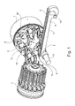
- FIG. 1 is a conveyor according to the invention for rod-shaped products 6 and 7 of the tobacco-processing industry, such as cigarettes, cigarillos or filter rods single or multiple length with and without filter with a maximum thickness of 15 mm, to recognize.
- the products 6 and 7 are cut in a preceding step by means of a rotating knife carrier of an endless strand in a predetermined length and on a guide means 3 on two parallel guideways 4 and 5 in two parallel strands of cut and juxtaposed products 6 and 7 in the direction of Transfer point I transports.
- the guide device 3 is pivotally mounted in a pivot bearing 13 and formed by means of a height adjustment device 12 in the transfer point I for fine adjustment height adjustable.
- the products 6 and 7 are transported away from a longitudinal conveyor 1 in the takeover point I of the guideways 4 and 5 and transported to a transfer point II.
- the transfer point II the products 6 and 7 are conveyed away transversely by a transverse conveyor 2, which has a plurality of mutually arranged pivotable lever arms and fixed or non-pivotable, rotatable lever arms with arranged thereon receptacles, in which the products 6 and 7 by Negative pressure be adopted.
- the pivotable lever arms of the cross conveyor 2 are preferably guided on a to the later described arms of the longitudinal conveyor 1 without collision trajectory. This can e.g.
- the course of the movement path of the recordings is selected such that the pivotable arms of the cross conveyor 2 radially enter from outside into the envelope of the arms of the longitudinal conveyor 1 and after taking over the products 6 and 7 again radially outward without that the lever arms thereby cut the path of movement of the remote from the longitudinal conveyor 1 recordings.
- This makes it possible, inter alia, to drive the longitudinal conveyor 1 and the transverse conveyor 2 with separately controllable individual drives, without causing the risk of a collision of the lever arms of the transverse conveyor 2 and the longitudinal conveyor 1.
- the longitudinal conveyor 1 has a rotatably drivable drum 33, projecting at the end face of a plurality of rotatably mounted lever arms 8, the center of which are arranged equidistant to each other and each equidistant from the axis of rotation of the drum 33.
- the lever arms 8 are each provided to the lever arms 8 rotatably mounted arms 9, which in each case one or more parallel to the feed direction of the Products 6 and 7 arranged receptacles 10 and 11 have.
- the receptacles 10 and 11 protrude laterally from the arms 9 and include a free space open on one side between them, into which the pivotable lever arms of the cross conveyor 2 dive to take over the products 7 remote from the transverse conveyor 2. Due to the later described drive the lever arms 8 and the rotatable mounting of the arms 9, the arms 9 and in particular the receptacles 10 and 11 thereby on a in FIG. 8 shown elliptical trajectory 43 moves.
- the longitudinal conveyor 1 with a drive device 24 in the form of an electric motor can be seen from behind.
- the entire longitudinal conveyor 1 is fixed by means of a holder 18 on a stand 14, to which below the longitudinal conveyor 1 also a positive guide 52 in the form of a fixed arm 15 is arranged with a curved guide slot 17 arranged therein and a pin 16 guided therein.
- a device 51 for displacement of the longitudinal conveyor 1 in the transverse direction to its longitudinal axis in the form of an engaging in the holder 18 and held on the stator 14 fixedly held threaded rod is provided on the stand 14, a coupling ring 20 can be seen, which is connected via a respective coupling arm 21 and gears 38 and 39, each with one of the arms 9.
- the view of the viewer facing the ends of the lever arms 8 are formed as eccentric 50 and stored in receptacles 32 of a swash plate 23, as in the Figures 5 and 6 can be seen.
- FIG. 3 is the longitudinal conveyor 1 from the FIG. 2 to recognize in section along the cutting direction AA.
- the drive device 24 drives the drum 33 via a shaft 25 rotationally, whereby the held in the drum 33 Lever arms 8 are taken to a rotary motion.
- the axes of rotation of the lever arms 8 run on a in the FIG. 8 with 42 designated circular path to.
- a gear 26 is fixed (see also FIG. 5 ), which meshes with a mounted in a housing 19 gear 29.
- the gear 29 meshes simultaneously with a likewise mounted in the housing 19 gear 28, which in turn meshes with a gear 27 which is rotatably connected to an eccentric disc 31.
- the eccentric disc 31 is reduced by two recesses 35 in the mass and balanced by a balancing mass 34 together with the swash plate 23 to the axis of rotation of the shaft 25.
- the gear pairings of the gears 26,29,28 and 27 together form a reversing gear 30, which drives the eccentric disc 31 to an opposite to the direction of rotation of the shaft 25 rotational movement at an identical speed.
- the number of teeth of the meshing gears 28 and 29 is preferably not identical and not identical to the numbers of teeth of the gears 26 and 27, so that the wear of the gears 28 and 29 is as uniform as possible.
- the swash plate 23 is rotatably mounted, which is driven in a rotation of the eccentric disk 31 against the rotational direction of the shaft 25 to a tumbling motion.
- a plurality of Justierbohronne 51 are provided on the housing 19, via which the housing 19 and the longitudinal conveyor 1 in total in predetermined angular positions opposite the holder 18 and the stator 14, for example by means of dowel pins or Absteckdornen, can be fixed.
- the Justierbohronne 51 are arranged so that the rotation of the housing 19 and fixing on the respective adjustment bore 51 automatically rotation of the in FIG. 8 shown elliptical trajectory 43 by a predetermined angle result.
- the Justierbohronne 51 thus facilitate the adjustment of the elliptical trajectory 43 insofar as a costly retiming or test driving the longitudinal conveyor 1 is no longer required.
- Each adjustment bore 51 stands for a preferred angular position of the elliptical trajectory.
- FIG. 6 is an enlarged sectional view through the drum 33 of the longitudinal conveyor 1 can be seen.
- the lever arms 8 each engage with a shaft 22 provided in the drum 33 recess and are taken by the drum 33 during the rotational movement in the circumferential direction.
- the drum 33 is rotatably connected to the coupling ring 20, so that the coupling arms 21, the rotational movement of the drum 33 also perform with.
- the ends of the lever arms 8 are each designed as an eccentric 50 and engage in corresponding receptacles 32 of the swash plate 23 a.
- the swash plate 23 thereby rotates with the drum 33 and is simultaneously driven by the counter-rotating eccentric disc 31 to a tumbling motion.
- the wobble of the swash plate 23 then passes through the arranged in the receptacles 32 eccentric 50 of the lever arms 8 to an opposite rotational movement of the lever arms 8 with respect to the rotating drum 33 about their own longitudinal axes, or in other words, to a compensation of the rotational movement of the drum 33 and the rotational movement of the lever arms 8 to the drum 33rd
- the speed of the arms 9 and the receptacles 10 and 11 on the elliptical trajectory 43 can be divided into a horizontal speed and a vertical speed.
- the vertical and horizontal speeds of the arms 9 thereby change during the revolution from a transfer point I, in which the arms 9 are moved almost horizontally, to a transfer point II, in which the arms 9 are moved almost vertically.
- the decisive for the takeover of the products in the transfer point I overspeed is the horizontal speed of the arms 9 and the recordings 10 and 11 at this point.
- a separately controllable second drive means 40 is also provided in the form of an electric motor.
- the rotor of the electric motor is non-rotatably connected to a hollow shaft 41, which in turn is non-rotatably connected to the eccentric disc 31.
- the second drive device 40 also drives the eccentric disk 31 in the opposite direction to the rotational movement of the first drive device 24 and the drum 33, whereby the same above-described movement of the lever arms 8 and the arms 9 arranged thereon is effected.
- the adjustment of the orientation of the elliptical trajectory 43 characterized in that the longitudinal conveyor 1 via a rotation in the FIG. 2 to be recognized threaded rod 52 along the guide on the stator 14 is moved transversely to its longitudinal axis.
- a pin 16 is provided, which projects into the curved or curved guide slot 17 and during the displacement movement of the longitudinal conveyor 1 controlled by the course of the guide slot 17 rotation of the longitudinal conveyor 1 forces a total of its longitudinal axis.
- the longitudinal axis of the longitudinal conveyor 1 corresponds to the longitudinal axis of the drive shaft of the drum 33 and the axis of rotation of the drum 33.
- the trajectory 43 of the arms 9 is thereby automatically with twisted.
- the rotation of the housing 19 and the eccentric disc 31 are rotated by a rotation of the gears 27,28 and 29 relative to the fixed to be considered gear 26 with respect to the in this case also to be regarded as a fixed drum 33, whereby the alignment of the lever arms 8 is also adjusted to the drum 33.
- the orientation of the lever arms 8 is here adjusted in the same manner as in the drive by the previously described rotating eccentric disc 31, with the difference that the drum 33 does not rotate in this case, ie it is only the relative rotation angle of the eccentric disc 31 to the drum 33 and thus only the orientation of the lever arms 8 adjusted to the drum 33.
- the elliptical trajectory of the arms 9 can also be adjusted by the drum 33 is rotated while holding the lever arms 9.
- This relative rotation of the eccentric disc 31 to the drum 33 and the lever arms 8 finally causes the rotation of the elliptical trajectory 43 in the dashed lines shown orientation 44 with a rotation of the major axes 45 and 46 of the ellipse in the position 47 and 48 by the angle A, in the same manner as in a rotation of the longitudinal conveyor 1 total about its longitudinal axis.
- the arms 9 be once again realigned after twisting the elliptical trajectory to correspond to the predetermined orientation in the takeover point and in the transfer point.
- the angular offset between the eccentric disc 31 and the drum 33 is effected by a separate control of the second drive means 40 by the eccentric disc 31 before starting the first drive means 24 with a stationary drum 33 or rotating drum 33 by the second drive means 40 to a relative angle to the drum 33 is rotated.
- the use of a second drive device 40 which can be controlled separately also permits fine adjustment of the elliptical trajectory 43 during the rotating drum 33.
- the alignment of the elliptical trajectory 43 and the first transfer point I can also be achieved as a function of the cutting movement of the products 6 and 7 to a predetermined rod length intersecting knife carrier done so that the positional accuracy of the products 6 and 7 can be improved to the recordings 10 and 11 by a corresponding control loop, resulting in the further transport of the products creates decisive advantages.
- the trajectory of the axes of rotation of the lever arms 8 is represented by a circular path 42.
- the elliptical trajectory of the arms 9 and the images arranged thereon 10 and 11 are shown as dashed ellipse 43 before adjustment and as ellipse 44 after adjustment.
- the original takeover point I can be adjusted by adjusting the elliptical trajectory 43 into the transfer point I '.
- the overspeeding of the receptacles 10 and 11 in the new takeover point I ' is automatically lower since the takeover point I' is now located at a point on the ellipse 44 in which the receptacles 10 and 11 move at a slower rate in the direction of movement of the supplied products be moved without that the speed of the revolving arms 9 must be changed. Further, by the rotation of the ellipse 44 and the transfer point II in the transfer point II 'adjusted. The transfer point II is always in the vicinity of the point where the receptacles 10 and 11 have the greatest distance in the lateral direction to the axis of rotation.
- the rotation of the elliptical trajectory 47 by the displacement of the longitudinal conveyor 1 is transverse to its longitudinal axis, as in FIG. 2 represented, particularly advantageous, since thereby the elliptical trajectory 43 automatically also transversely to the axis of rotation of the drum 33, as in the FIG. 9 is shown, moved.
- the height or side shift of the transfer point I and the transfer point II can be compensated so far that the transfer point exclusively horizontally and the transfer point II are moved only vertically.
- the rotation of the arms 9 to the lever arms 8 is made possible in the present embodiments by the coupling ring 20, which is slightly rotated to adjust the arms 9 at a standstill drum 33.
- the coupling ring 20 also has a number of arms 9 corresponding number of coupling arms 21.
- the coupling arms 21 are rotatably connected to the ends in each case with a shaft 37, which upon rotation of the coupling ring 20 to their Longitudinal axes are rotated.
- the rotational movement of the shafts 37 is transmitted via a gear with two or more gears 38 and 39 and a rotational movement transmitting belt on a rotatably mounted shaft 36 of the arms 9, so that the arms 9 in a rotation of the shafts 37 in the lever arms 8 to the longitudinal axes of their shafts 36 are rotated.
- the alignment of the receptacles 10 and 11 can be adjusted again so far after the adjustment of the elliptical trajectory 43 that they are again aligned horizontally and / or in the direction of the transfer point I supplied products 6 and 7.
- lever arms 8 eccentric 50, with which the lever arms 8 are rotatably mounted in corresponding receptacles 32 of the swash plate 23.
- the lever arms 8 comprise in addition to the eccentrics 50 each have a shaft 22 which are penetrated by the shafts 37 respectively.
- the lever arms 8 each have a frontally projecting radial arm 53, in whose radially outer portion in each case the shafts 36 of the arms 9 are rotatably mounted.
- the lever arms 8 are driven due to the wobbling movement of the swash plate 33 and the bearing of the lever arms 8 in the receptacles 32 via the eccentric 50 to a relative to the rotational movement of the drum 33 opposite rotational movement of the same speed. Because of this opposing rotational movement of the lever arms 8, the shafts 36 of the arms 9, which are mounted in the outer sections of the radial arms 53, are moved on the elliptical trajectory 43.
- the movement of the arms 9 is coupled only insofar with the movement of the lever arms 8 that the axes of rotation of the shafts 36 are guided on the elliptical trajectory 43, but on the other hand, a rotational movement about the axes of rotation of the shafts 36 relative to the lever arms 8 execute.
- the rotational movement of the shafts 36 to the lever arms 8 is enforced by the rotating with the drum 33 shafts 37, which are fixed relative to the drum 33 via the coupling arms 21.
Abstract
Description
Die Erfindung betrifft einen Längsförderer für stabförmige Produkte der Tabak verarbeitenden Industrie mit den Merkmalen des Oberbegriffs von Anspruch 1, eine Fördereinrichtung mit einem Längsförderer mit den Merkmalen der Oberbegriffe der Ansprüche 16 oder 18 und ein Verfahren zum Betreiben eines Längsförderers mit den Merkmalen des Oberbegriffs von Anspruch 19.The invention relates to a longitudinal conveyor for rod-shaped products of the tobacco industry with the features of the preamble of
Solche Längsförderer und Fördereinrichtungen sind im Stand der Technik bekannt und dienen dazu, die auf einer Bahn oder auf zwei oder mehr parallelen Bahnen kontinuierlich zugeführten Produkte abzufördern und einem die Produkte quer zu der Zuführbewegung abfördernden Querförderer zuzuführen, wobei der Förderprozess auch umgekehrt ablaufen kann.Such longitudinal conveyors and conveyors are known in the art and serve to remove the products continuously fed on one web or on two or more parallel webs and to feed the products transversely to the feed movement abfördernden cross conveyor, wherein the conveying process can also run in reverse.
Der Längsförderer ist aus einer um eine erste Drehachse rotatorisch antreibbaren Trommel mit einer Mehrzahl von rotatorisch um zweite Drehachsen antreibbaren Hebelarmen gebildet, wobei die zweiten Drehachsen parallel zu der ersten Drehachse angeordnet sind. Die Hebelarme werden während der Drehbewegung der Trommel zu einer zu der Drehbewegung der Trommel gegensinnigen Drehbewegung mit einer identischen Drehzahl oder mit einem ganzzahligen Vielfachen der Drehzahl der Trommel angetrieben. Die beschriebene Drehbewegung der Hebelarme ist die Drehbewegung, welche ein externer Betrachter wahrnehmen würde. An den Enden der Hebelarme sind vorstehende Arme mit einer der Anzahl der Bahnen entsprechenden Anzahl von Aufnahmen vorgesehen, welche parallel zu den Bahnen ausgerichtet und über eine Druckluftleitung in einem Übernahmepunkt und in einem Übergabepunkt mit Druckluft beaufschlagbar sind. Mit Druckluft ist erfindungsgemäß sowohl Überdruck als auch Unterdruck gemeint. Die Arme werden aufgrund der gegensinnigen Drehbewegung der Hebelarme um ihre Längsachse zu der Trommel auf einer elliptischen Bewegungsbahn bewegt und werden dabei während der Drehbewegungen der Trommel und der Hebelarme in einer konstanten, vorzugsweise horizontalen Ausrichtung gehalten. Die Drehbewegung der Hebelarme zu der Trommel kann z.B. über ein aufwendiges, schnell laufendes Getriebe, insbesondere durch ein Koppelgetriebe, verwirklicht werden, welches die Drehbewegung der Antriebseinrichtung oder der Trommel oder der Trommel selbst auf die Hebelarme überträgt. Das Getriebe ist dabei durch ein zentrales Sonnenrad und an den Hebelarmen angeordneten Planetenräder gebildet und erfordert eine aufwendige Schmierung mit einer entsprechenden Abdichtung. Insgesamt ist das Getriebe konstruktiv sehr aufwendig und teuer.The longitudinal conveyor is formed of a rotationally driven about a first axis of rotation drum having a plurality of rotationally driven about second axes of rotation lever arms, wherein the second axes of rotation are arranged parallel to the first axis of rotation. The lever arms are driven during the rotational movement of the drum to an opposite to the rotational movement of the drum rotational movement at an identical speed or at an integral multiple of the rotational speed of the drum. The described rotation of the lever arms is the rotational movement which an external viewer would perceive. At the ends of the lever arms are protruding arms with one of Number of tracks provided corresponding number of shots, which are aligned parallel to the tracks and acted upon by a compressed air line in a takeover point and in a transfer point with compressed air. With compressed air according to the invention, both overpressure and negative pressure meant. The arms are moved due to the opposite rotational movement of the lever arms about its longitudinal axis to the drum on an elliptical trajectory and are held during the rotational movements of the drum and the lever arms in a constant, preferably horizontal orientation. The rotational movement of the lever arms to the drum can be realized, for example via a complex, high-speed transmission, in particular by a coupling gear, which transmits the rotational movement of the drive means or the drum or the drum itself to the lever arms. The transmission is formed by a central sun gear and arranged on the lever arms planetary gears and requires a complex lubrication with a corresponding seal. Overall, the transmission is structurally very expensive and expensive.
Die stabförmigen Produkte werden in dem unteren tiefsten Punkt der Ellipse (erster Punkt) aus der linearen Zuführung abgefördert und in dem darauffolgenden seitlichen von der Drehachse am weitesten entfernten Punkt der Ellipse (zweiter Punkt) an den Querförderer übergeben. Bei einer richtigen Einstellung des Bewegungsablaufes der Aufnahmen werden diese in dem ersten Umkehrpunkt nahezu parallel zu den Längsachsen der zugeführten stabförmigen Produkte und in dem zweiten Umkehrpunkt nahezu quer zu den Längsachsen der stabförmigen Produkte bewegt.The rod-shaped products are conveyed out of the linear feed in the lower lowest point of the ellipse (first point) and transferred to the transverse conveyor in the subsequent lateral point of the ellipse (second point) farthest from the rotation axis. With a correct adjustment of the sequence of movements of the images they are moved in the first turning point almost parallel to the longitudinal axes of the supplied rod-shaped products and in the second turning point almost transverse to the longitudinal axes of the rod-shaped products.
Ein solcher Längsförderer ist z.B. aus der
Ein Problem bei dem Transport der Produkte ist, dass die Mulden der Arme des Längsförderers in dem Übernahmepunkt mit einer höheren Geschwindigkeit als die Geschwindigkeit der zugeführten Produkte (auch Übergeschwindigkeit genannt) bewegt werden müssen, damit die dem Längsförderer auf der Führungseinrichtung zugeführten Produkte auf keinen Fall aufstauen oder während der Übernahmebewegung mit dem nachfolgenden Produkt kollidieren können. Die Übergeschwindigkeit ist dabei außerdem abhängig von der Stablänge der Produkte, da die Drehzahl des Längsförderers der Fördereinrichtungen auch für den Transport von Produkten unterschiedlicher Stablänge gleich ist und die Stranggeschwindigkeit der zugeführten Produkte auf eine vorbestimmte Anzahl von zu übernehmenden Produkten je Zeiteinheit abgestimmt werden muss. Die Produkte werden aus diesen Gründen unter ungünstigen Umständen mit einer bis zu zweifachen Übergeschwindigkeit im Vergleich zu der Zuführgeschwindigkeit der Produkte übernommen. Die Mulden selbst weisen ferner eine bestimmte Oberflächenrauheit auf, welche die wirkenden Reibkräfte zwischen den Mulden und den Produkten bei der Übernahme mitbestimmt. Die Übergeschwindigkeit kann einen Schlupf zwischen den Produkten und den Aufnahmen zur Folge haben, was zu einer Lageabweichung der Produkte von einer vorbestimmten Soll-Lage relativ zu den Aufnahmen während des nachfolgenden Transportweges führen kann. Diese Lageabweichung muss anschließend an einer Axialscheibe eines nachfolgenden Querförderers aufwendig weggetaumelt werden. Im Extremfall kann die wegzutaumelnde Lageabweichung der Produkte bis zu 10 mm betragen. Ferner führt die notwendige Übergeschwindigkeit zu einer ruckartigen Belastung der Produkte, welche zu einem unerwünschten Kopfausfall der Produkte führt. Die Übergeschwindigkeit sollte zur Vermeidung oder Minimierung der vorgenannten Effekte grundsätzlich so gering wie möglich gewählt werden.A problem with the transport of the products is that the troughs of the arms of the longitudinal conveyor have to be moved at the takeover point at a speed higher than the speed of the supplied products (also called overspeed), so that the products fed to the longitudinal conveyor on the guide means by no means damming or colliding with the subsequent product during the takeover. The overspeeding is also dependent on the rod length of the products, since the speed of the longitudinal conveyor of the conveyors is the same for the transport of products of different rod length and the strand speed of the supplied products must be matched to a predetermined number of products to be accepted per unit time. For these reasons, the products are taken under unfavorable conditions at up to twice the overspeed compared to the feed rate of the products. The troughs themselves also have a certain surface roughness, which co-determines the frictional forces acting between the troughs and the products during takeover. The overspeeding may result in slippage between the products and the receptacles, which may result in a positional deviation of the products from a predetermined desired position relative to the receptacles during the subsequent transport path. This positional deviation must then be thawed away consuming at a Axialscheibe a subsequent cross conveyor. In extreme cases, the wegzutaumelnde positional deviation of the products can be up to 10 mm. Furthermore, the necessary overspeed leads to a jerky loading of the products, which leads to an undesirable head failure of the products. The overspeed should always be as low as possible to avoid or minimize the aforementioned effects.
Ferner muss der Längsförderer synchronisiert zu der Bewegung eines die Produkte von einem endlosen Strang in einer vorbestimmten Länge abschneidenden rotierenden Messerträgers angetrieben werden, damit sich die Aufnahmen in dem Übernahmepunkt immer reproduzierbar über einem zu übernehmenden Produkt befinden. Die Übergeschwindigkeit und die Synchronisation können in gewissen Grenzen jeweils über die Anzahl der Arme und die Längen der Aufnahmen eingestellt werden. Die Anpassung der Längen der Aufnahmen an die Stablänge der Produkte ist mit einem sehr hohen Aufwand verbunden, welcher im Extremfall bis zum Austausch der gesamten Baugruppe oder sogar des gesamten Längsförderers reichen kann. Da der Längsförderer und die Trommel des Längsförderers konstruktiv sehr aufwendige und teure Bauteile sind, ist die Umrüstung der Fördereinrichtung in diesem Fall sehr zeitaufwendig und teuer. Ferner entstehen dadurch erhebliche Kosten für die Vorhaltung von Längsförderern oder Trommeln mit einer unterschiedlichen Anzahl von Hebelarmen und Aufnahmen bzw. von Aufnahmen mit unterschiedlichen Längen.Furthermore, the longitudinal conveyor must be driven in synchronism with the movement of a rotating knife carrier cutting off the products from an endless strand of a predetermined length so that the pick-ups in the transfer point are always reproducible over a product to be picked up. The overspeed and the synchronization can be adjusted within certain limits in each case on the number of arms and the lengths of the recordings. The adaptation of the lengths of the recordings to the rod length of the products is associated with a very high cost, which in extreme cases can extend to the replacement of the entire assembly or even the entire longitudinal conveyor. Since the longitudinal conveyor and the drum of the longitudinal conveyor are structurally very complex and expensive components, the conversion of the conveyor in this case is very time consuming and expensive. Furthermore, this results in considerable costs for the provision of longitudinal conveyors or drums with a different number of lever arms and recordings or recordings with different lengths.
Vor diesem Hintergrund liegt der Erfindung die Aufgabe zugrunde, einen Längsförderer und eine Fördereinrichtung zu schaffen, welche mit möglichst geringem Aufwand und unter Verursachung von möglichst geringen Kosten für Produkte mit einer anderen Stablänge verwendet werden können, wobei die Belastung der Produkte bei der Übernahme möglichst gering sein soll.Against this background, the invention has the object to provide a longitudinal conveyor and a conveyor, which can be used with the least possible effort and causing the lowest possible cost of products with a different rod length, the load of the products in the acquisition as low as possible should be.
Die Aufgabe wird erfindungsgemäß durch einen Längsförderer mit den Merkmalen von Anspruch 1, durch eine Fördereinrichtung mit den Merkmalen von Anspruch 14 oder 16 und durch ein Verfahren mit den Merkmalen von Anspruch 17 gelöst.The object is achieved by a longitudinal conveyor with the features of
Weitere bevorzugte Weiterentwicklungen der Erfindung sind den Unteransprüchen, den Figuren und der zugehörigen Beschreibung zu entnehmen.Further preferred developments of the invention can be taken from the subclaims, the figures and the associated description.
Gemäß dem Grundgedanken der Erfindung nach Anspruch 1 wird vorgeschlagen, dass der Längsförderer dazu eingerichtet ist, die elliptische Bewegungsbahn der Aufnahmen zu verstellen. Mit der Verstellung der Ausrichtung der elliptischen Bewegungsbahn ist dabei die Verdrehung der elliptischen Bewegungsbahn um die Drehachse der Trommel des Längsförderers gemeint. Dabei wird die elliptische Bewegungsbahn bevorzugt in einer Ebene verdreht, so dass sich die Lage der Aufnahmen quer zu der Bewegungsrichtung nicht verändert.According to the basic idea of the invention according to
Die Erfindung nutzt dabei die Erkenntnis, dass die Aufnahmen auf der elliptischen Bewegungsbahn während des Umlaufens mit verschiedenen Geschwindigkeitskomponenten in Richtung der Längsachsen der Produkte und quer zu den Längsachsen der Produkte bewegt werden. Dadurch kann die Übergeschwindigkeit der Aufnahmen in dem Übernahmepunkt bei gleicher Drehzahl des Längsförderers, mit einer identischen Anzahl von Armen und einer identischen Länge der Aufnahmen verstellt werden, indem die Produkte an einer anderen Stelle der elliptischen Bewegungsbahn übernommen werden. Durch die Verdrehung der elliptischen Bewegungsbahn wird der tiefste Punkt der elliptischen Bewegungsbahn auf einen anderen Punkt der elliptischen Bewegungsbahn verstellt, so dass die Aufnahmen in dem tiefsten Punkt der Ellipse ohne eine Veränderung der Drehzahl eine andere Geschwindigkeit in Richtung der Längsachsen der Produkte aufweisen. Ferner kann dadurch auch der Übernahmepunkt selbst verändert und an eine andere Stablänge der Produkte angepasst werden. Mit dem veränderbaren Übernahmepunkt bzw. der veränderbaren Übergeschwindigkeit wird eine zusätzliche Einstellgröße geschaffen, wodurch derselbe Längsförderer mit einer identischen Anzahl von Armen und Aufnahmen identischer Länge für eine Abförderung von Produkten mit einer größeren Bandbreite unterschiedlicher Stablängen verwendet werden kann. Ferner kann dadurch die Übergeschwindigkeit in dem Übernahmepunkt verringert werden, wodurch sich der Vorteil ergibt, dass die auf die Produkte bei der Übernahme wirkenden ruckartigen Beschleunigungskräfte und der mögliche Schlupf reduziert werden, und die Produkte dadurch mit einer geringeren Abweichung der Ist-Lage von der Soll-Lage relativ zu den Aufnahmen übernommen werden bzw. der Kopfausfall verringert werden kann. Sofern die Ist-Lage der Produkte von der Soll-Lage dennoch abweicht, kann diese Abweichung aber auch an einer Axialscheibe eines nachfolgenden Querförderers noch zusätzlich weggetaumelt werden. Insbesondere können der Übernahmepunkt und die Übergeschwindigkeit aufgrund der einfachen Verstellbarkeit auch in Abhängigkeit von dem Bewegungsablauf eines die Produkte in einem vorangegangenen Arbeitsschritt von einem Endlosstrang in einer vorbestimmten Länge abschneidenden rotierenden Messerträgers erfolgen. Durch die verbesserte Übernahme kann die im Anschluss noch wegzutaumelnde Lageabweichung der Produkte in den Aufnahmen eines nachfolgenden Querförderers deutlich reduziert werden. Ferner können durch die verringerte Übergeschwindigkeit die bei der Übernahme der Produkte auf die Produkte wirkenden Kräfte und der dadurch begründete Kopfausfall verringert werden.The invention uses the knowledge that the images are moved on the elliptical trajectory during orbit with different speed components in the direction of the longitudinal axes of the products and transversely to the longitudinal axes of the products. Thereby, the overspeed of the recordings in the takeover point at the same speed of the longitudinal conveyor, can be adjusted with an identical number of arms and an identical length of the recordings by the products are taken over at another point of the elliptical trajectory. As a result of the rotation of the elliptical trajectory, the lowest point of the elliptical trajectory is adjusted to another point of the elliptical trajectory, so that the exposures at the lowest point of the ellipse have a different velocity in the direction of the longitudinal axes of the products without a change in rotational speed. Furthermore, the takeover point itself can also be changed and adapted to a different rod length of the products. With the variable takeover point or the variable overspeed is an additional setting created, whereby the same longitudinal conveyor can be used with an identical number of arms and receptacles of identical length for a removal of products with a wider range of different rod lengths. Furthermore, this can reduce the overspeed in the takeover point, which has the advantage that the jerky acceleration forces acting on the products during takeover and the possible slip are reduced, and thereby the products with a smaller deviation of the actual position from the target Position taken relative to the recordings or the head loss can be reduced. If the actual position of the products nevertheless deviates from the desired position, this deviation can, however, also be further thrown away on an axial disk of a subsequent transverse conveyor. In particular, the takeover point and the overspeed due to the simple adjustability also depending on the sequence of movement of the products in a previous step from a continuous strand in a predetermined length trimming rotating blade carrier can be done. As a result of the improved takeover, the positional deviation of the products, which still has to be de-agitated later, can be significantly reduced in the receptacles of a subsequent transverse conveyor. Furthermore, the reduced overspeed can reduce the forces acting on the products when taking over the products and the resulting head failure.
Die Verstellung der elliptischen Bewegungsbahn kann konstruktiv besonders einfach dadurch erfolgen, indem der Längsförderer und insbesondere der Antrieb der Trommel und der Hebelarme an einer dafür vorgesehenen Schnittstelle voneinander gelöst werden und in einer anderen Ausrichtung zueinander wieder montiert werden. Durch die veränderte Ausrichtung kann die elliptische Bewegungsbahn einmalig verstellt werden, wobei der Längsförderer anschließend wieder in der herkömmlichen Weise betrieben wird. Die konstruktive Schnittstelle ist dabei bevorzugt durch eine montagefreundlich zu lösende Verbindung gebildet, bei der bestimmte Baugruppen, wie z.B. die Trommel mit den Hebelarmen oder die Antriebswelle mit einem Teil des Drehrichtungsumkehrgetriebes, nicht demontiert werden müssen und nur als Baugruppen relativ zueinander verdreht und in der verdrehten Ausrichtung wieder zusammengebaut werden müssen. Besonders bevorzugte Schnittstellen sind dabei das Drehrichtungsumkehrgetriebe mit einer Schnittstelle zwischen den mit den Hebelarmen und der Antriebswelle verbundenen Zahnrädern oder auch eine Schnittstelle zwischen einer die Hebelarme antreibenden Exzenterscheibe und dem die Exzenterscheibe antreibenden Antrieb.The adjustment of the elliptical trajectory can be structurally particularly simple in that the longitudinal conveyor and in particular the drive of the drum and the lever arms are released from each other at an interface provided for this purpose and reassembled in a different orientation to each other. Due to the changed orientation, the elliptical Movement be adjusted once, the longitudinal conveyor is then operated again in the conventional manner. The structural interface is preferably formed by a connection easy to be loosened connection, in which certain assemblies, such as the drum with the lever arms or the drive shaft with a part of the reversing direction, must not be dismantled and rotated only as assemblies relative to each other and in the twisted Alignment need to be reassembled. Particularly preferred interfaces are the direction of rotation reversal gear with an interface between the connected to the lever arms and the drive shaft gears or an interface between the eccentric disc driving the lever arms and the driving the eccentric disc drive.
Eine ausreichende Anpassung des Übernahmepunktes und/oder der Übergeschwindigkeit an die individuell vorgesehene Stablänge der Produkte kann dadurch erzielt werden, indem die elliptische Bewegungsbahn um einen Winkel von +/- 15 Grad verschwenkbar ist.A sufficient adjustment of the takeover point and / or the overspeed to the individually provided rod length of the products can be achieved by the elliptical trajectory is pivotable by an angle of +/- 15 degrees.
Weiter wird vorgeschlagen, dass die Aufnahmen zu den Hebelarmen gemeinsam verstellbar ausgebildet sind. Durch die gemeinsame Verstellbarkeit der Aufnahmen können diese nach der Verstellung der elliptischen Bewegungsbahn soweit nachgestellt werden, dass sie anschließend wieder eine horizontale und/oder eine an die Ausrichtung der Produkte in dem Übernahmepunkt und dem Übergabepunkt angepasste Ausrichtung aufweisen, wobei durch die gemeinsame Verstellung der Arme die Verstellung als solches vereinfacht wird und außerdem die Ausrichtung der Arme zueinander beibehalten wird.It is also proposed that the receptacles are designed to be adjustable together to the lever arms. Due to the joint adjustability of the images they can be readjusted so far after the adjustment of the elliptical trajectory that they then again have a horizontal and / or aligned to the orientation of the products in the takeover point and the transfer point alignment, wherein the joint adjustment of the arms the adjustment as such is simplified and also the alignment of the arms with each other is maintained.
Eine weitere vorteilhafte Ausbildung der Erfindung kann dadurch verwirklicht werden, indem die Hebelarme in einer Taumelscheibe geführt sind, welche mittels einer zu der Drehrichtung der Trommel gegensinnig angetriebenen Exzenterscheibe zu einer Taumelbewegung angetrieben wird. Durch die Taumelscheibe kann die bisher erforderliche Übertragung der Drehbewegung der Hebelarme über das aufwendige Koppelgetriebe mit einzelnen Zahnrädern durch die Verwendung eines einzigen Teiles erheblich vereinfacht werden, wodurch die Kosten und die Montagezeit erheblich reduziert werden können. Dabei ist es insbesondere von Vorteil, dass die Taumelscheibe durch ein einziges Teil, nämlich durch die Exzenterscheibe, zu der Taumelbewegung antreibbar ist, welche schließlich die Drehbewegung der Hebelarme zu der Trommel des Längsförderers bewirkt. Die zu der Drehbewegung der Trommel gegensinnige Drehbewegung der Hebelarme wird hier allein durch die gegensinnig angetriebene Exzenterscheibe und die Taumelscheibe bewirkt, was unabhängig von der Verstellung der elliptischen Bewegungsbahn der Arme bereits eine erhebliche Vereinfachung des konstruktiven Aufbaus des Längsförderers darstellt.A further advantageous embodiment of the invention can be realized by the lever arms are guided in a swash plate which is driven by means of an eccentric disc driven in opposite directions to the direction of rotation of the drum to a tumbling motion. Due to the swash plate, the previously required transmission of the rotational movement of the lever arms on the complex coupling gear with individual gears can be considerably simplified by the use of a single part, whereby the cost and assembly time can be significantly reduced. It is particularly advantageous that the swash plate can be driven by a single part, namely by the eccentric disc to the tumbling motion, which finally causes the rotation of the lever arms to the drum of the longitudinal conveyor. The opposite to the rotational movement of the drum rotational movement of the lever arms is effected here alone by the oppositely driven eccentric disc and the swash plate, which already represents a considerable simplification of the structural design of the longitudinal conveyor regardless of the adjustment of the elliptical trajectory of the arms.
Die Taumelbewegung der Taumelscheibe wird dabei besonders einfach in eine Drehbewegung der Hebelarme umgesetzt, indem die Taumelscheibe Aufnahmen aufweist, in die die Hebelarme mit einem Exzenter eingreifen. Da die Hebelarme mit der Trommel umlaufen und die Taumelscheibe über die Hebelarme gleichfalls mit der Trommel mitdreht, führen die Aufnahmen in der Taumelscheibe bei einer entsprechenden Auslegung der Exzenter eine Drehbewegung um die Drehachsen der Hebelarme aus, welche durch den Eingriff der Hebelarme über die Exzenter in eine Drehbewegung der Hebelarme gegenüber der Taumelscheibe und der Trommel umgewandelt wird. Dabei ist es wichtig, dass die Hebelarme mit einer identischen Exzentrizität an der Trommel gelagert sind, damit sich die Drehbewegungen nicht gegenseitig blockieren. Daher ist das Gesamtsystem ohne die bisher erforderliche Zahnspieleinstellung spielfrei funktionsfähig.The wobbling motion of the swash plate is particularly easily implemented in a rotational movement of the lever arms by the swash plate has receptacles in which engage the lever arms with an eccentric. Since the lever arms rotate with the drum and the swash plate also rotates about the lever arms with the drum, the recordings in the swash plate with a corresponding design of the eccentric perform a rotational movement about the axes of rotation of the lever arms, which by the engagement of the lever arms on the eccentric in a rotational movement of the lever arms relative to the swash plate and the drum is converted. It is important that the lever arms are mounted with an identical eccentricity on the drum, so that the rotational movements do not block each other. Therefore, the entire system without the previously required backlash setting is free of play functional.
Gemäß einer weiteren bevorzugten Ausführungsform der Erfindung wird vorgeschlagen, dass die Exzenterscheibe über ein an die Antriebseinrichtung der Trommel angekoppeltes Drehrichtungsumkehrgetriebe antreibbar ist. Durch das Drehrichtungsumkehrgetriebe können die Trommel und die Exzenterscheibe von ein und derselben Antriebseinrichtung angetrieben werden, wobei die Drehzahl zum Antrieb der Exzenterscheibe weder unter- noch übersetzt werden muss, da die Exzenterscheibe mit einer identischen Drehzahl angetrieben wird. Neben der Verwendung einer einzigen Antriebseinrichtung ergibt sich dadurch ferner der Vorteil, dass die Bewegung der Trommel und der Exzenterscheibe miteinander gekoppelt sind.According to a further preferred embodiment of the invention it is proposed that the eccentric disc is drivable via a coupled to the drive means of the drum rotation direction reversing gear. By reversing the direction of rotation, the drum and the eccentric disc can be driven by one and the same drive means, the rotational speed for driving the eccentric disc neither under nor has to be translated, since the eccentric is driven at an identical speed. In addition to the use of a single drive means, this also results in the advantage that the movement of the drum and the eccentric disc are coupled together.
Alternativ wird vorgeschlagen, dass die Exzenterscheibe über eine zweite Antriebseinrichtung ansteuerbar ist, welche von der Antriebseinrichtung der Trommel getrennt ansteuerbar ist. Durch die zweite Antriebseinrichtung werden zwar die Kosten erhöht, es ergibt sich aber der für die vorliegende Erfindung wesentliche Vorteil, dass die Bewegung der Trommel und die Exzenterscheibe unabhängig voneinander ansteuerbar sind. Da sich die elliptische Bewegungsbahn der Aufnahmen aus einer Überlagerung der Drehbewegung der Hebelarme mit der Trommel und der Drehbewegung der Hebelarme zu der Trommel, bewirkt durch die von der Exzenterscheibe angetriebene Taumelscheibe, ergibt, kann die Ausrichtung der elliptischen Bewegungsbahn besonders einfach dadurch verstellt werden, indem die Exzenterscheibe durch eine getrennte Ansteuerung der zweiten Antriebseinrichtung geringfügig zu der Trommel verdreht wird, d.h. indem die beiden Bewegungsabläufe zueinander verdreht werden. Die Verstellung der elliptischen Bewegungsbahn kann z.B. durch einen Offset verstellt werden, indem z.B. die Drehwinkelstellung der Exzenterscheibe zu der Trommel geringfügig verstellt wird, bevor die eigentliche Antriebsbewegung der Trommel beginnt.Alternatively, it is proposed that the eccentric disc is controllable via a second drive device, which can be controlled separately from the drive device of the drum. Although the cost is increased by the second drive device, but it results in the significant advantage for the present invention that the movement of the drum and the eccentric disc are independently controllable. Since the elliptical trajectory of the images of a superposition of the rotational movement of the lever arms with the drum and the rotational movement of the lever arms to the drum, caused by the driven of the eccentric disc swash plate results, the alignment of the elliptical trajectory can be particularly easily adjusted by the eccentric disc is rotated slightly by a separate control of the second drive means to the drum, that is, by the two movements are rotated to each other. The adjustment The elliptical trajectory can be adjusted, for example by an offset, for example, by the angular position of the eccentric disc is slightly adjusted to the drum before the actual drive movement of the drum begins.
Ferner wird vorgeschlagen, dass die Einrichtung zur Verstellung der elliptischen Bewegungsbahn der Arme durch eine Einrichtung zur Verschiebung des Längsförderers quer zu seiner Drehachse und eine mit den Hebelarmen gekoppelte Zwangsführung gebildet ist, durch welche die Hebelarme während der Verschiebung des Längsförderers rotatorisch um ihre Drehachse verstellt werden. Die durch die Zwangsführung erzwungene Bewegung kann dabei unmittelbar oder mittelbar über eine Koppelung auf die Hebelarme übertragen werden, wichtig ist nur, dass durch die Zwangsführung die Ausrichtung der Hebelarme zu der Trommel verändert werden kann. Dies kann z.B. durch eine Verstellung eines der Teile der Baugruppe des Drehrichtungsumkehrgetriebes erfolgen, welches bewegungstechnisch mittelbar oder unmittelbar mit der Exzenterscheibe gekoppelt ist. Der ursprüngliche Übernahmepunkt auf der elliptischen Bewegungsbahn wird bei der Verdrehung der elliptischen Bewegungsbahn zwangsweise auch in der Höhe verschoben. Diese Verschiebung des ursprünglichen Übernahmepunktes in der Höhe kann durch die vorgeschlagene Lösung im Idealfall bei einer entsprechenden Ausrichtung der Verschieberichtung des Längsförderers und der Zwangsführung soweit kompensiert werden, dass der Übernahmepunkt ausschließlich horizontal bzw. in Richtung der Längsachsen der Produkte verschoben wird, da in diesem Fall die elliptische Bewegungsbahn zusätzlich insgesamt auch quer zu der Drehachse des Längsförderers verschoben wird.It is also proposed that the means for adjusting the elliptical trajectory of the arms by a means for displacement of the longitudinal conveyor is formed transversely to its axis of rotation and coupled to the lever arms forced operation, by which the lever arms are rotationally adjusted during the displacement of the longitudinal conveyor about its axis of rotation , The forced by the forced operation movement can be transmitted directly or indirectly via a coupling to the lever arms, it is only important that the alignment of the lever arms can be changed to the drum by the positive guidance. This can e.g. take place by adjusting one of the parts of the assembly of the direction of rotation reversing gear, which is motion-related indirectly or directly coupled to the eccentric disc. The original takeover point on the elliptical trajectory is forcibly moved in the rotation of the elliptical trajectory in height. This shift of the original takeover point in height can be compensated by the proposed solution ideally with a corresponding orientation of the direction of displacement of the longitudinal conveyor and the forced operation so that the takeover point is moved only horizontally or in the direction of the longitudinal axes of the products, since in this case the elliptical trajectory is additionally displaced overall also transversely to the axis of rotation of the longitudinal conveyor.
Alternativ kann die Einrichtung zur Verstellung der elliptischen Bewegungsbahn der Arme auch durch eine mit den Hebelarmen gekoppelte verschiebbare Zwangsführung gebildet sein, so dass der Längsförderer selbst in diesem Fall zur Verschiebung der elliptischen Bewegungsbahn nicht verschieblich ausgebildet sein muss.Alternatively, the means for adjusting the elliptical trajectory of the arms also by one with the lever arms coupled displaceable positive guide be formed, so that the longitudinal conveyor itself must not be designed to be displaceable in this case to move the elliptical trajectory.
In diesem Fall kann die rotatorische Verstellbewegung der Hebelarme besonders einfach erzwungen werden, indem die Verschieberichtung des Längsförderers oder der Zwangsführung oder die Richtung der Zwangsführung selbst einen gekrümmten Verlauf und die jeweils andere Richtung einen geradlinigen Verlauf aufweist.In this case, the rotational adjustment of the lever arms can be particularly easily enforced by the direction of displacement of the longitudinal conveyor or the positive guide or the direction of the positive guide itself has a curved course and the other direction has a straight course.
Da die Verstellung der Winkelausrichtung der elliptischen Bewegungsbahn durch eine Verstellung der Ausrichtung der Exzenterscheibe zu der Trommel, also durch eine Verstellung zweier Teile des Längsförderers zueinander, erfolgt, und der Längsförderer selbst aus einer Vielzahl von zueinander bewegbaren Einzelteilen zusammengesetzt ist, ist es sinnvoll, dass die Stellbewegung durch eine Einrichtung zur Verschiebung des Längsförderers und eine Zwangsführung erzwungen wird, welche sich in einer festen räumlichen Zuordnung zueinander befinden.Since the adjustment of the angular orientation of the elliptical trajectory by an adjustment of the orientation of the eccentric disc to the drum, ie by adjusting two parts of the longitudinal conveyor to each other, takes place, and the longitudinal conveyor itself is composed of a plurality of mutually movable items, it makes sense that the adjusting movement is forced by a device for displacement of the longitudinal conveyor and a positive guidance, which are in a fixed spatial relationship to each other.
Weiter wird vorgeschlagen, dass die Zwangsführung durch eine in einer Ebene quer zu den Drehachsen der Hebelarme gekrümmte Führungskulisse gebildet ist, in die ein mit den Hebelarmen bewegungstechnisch gekoppelter Zapfen eingreift.It is further proposed that the positive guidance is formed by a guide slot which is curved in a plane transverse to the axes of rotation of the lever arms and into which engages a journal coupled in terms of motion with the lever arms.
Alternativ kann die elliptische Bewegungsbahn der Arme durch eine rotatorische Verstellung des Längsförderers um die erste Drehachse verstellbar sein. In diesem Fall wird der gesamte Längsförderer um seine Längs- bzw. Drehachse verdreht. Diese Lösung weist den Vorteil auf, dass ein Längsförderer herkömmlicher Bauart verwendet werden kann, es muss lediglich eine Möglichkeit vorgesehen werden, den Längsförderer entsprechend zu verdrehen. Die Verdrehung des Längsförderers kann einmalig bei der Montage erfolgen oder auch mittels einer Einstellvorrichtung anschließend nach der Montage des Längsförderers vorgenommen werden, wobei die Einstellvorrichtung den Vorteil aufweist, dass der Längsförderer bei einem Produktwechsel bzw. zu einer Änderung der Übergeschwindigkeit nicht demontiert werden muss.Alternatively, the elliptical trajectory of the arms can be adjusted by a rotational adjustment of the longitudinal conveyor about the first axis of rotation. In this case, the entire longitudinal conveyor is rotated about its longitudinal or rotational axis. This solution has the advantage that a longitudinal conveyor of conventional design can be used, it only has one Possibility to be provided to turn the longitudinal conveyor accordingly. The rotation of the longitudinal conveyor can be done once during assembly or can be carried out by means of a setting subsequently after the installation of the longitudinal conveyor, the adjustment has the advantage that the longitudinal conveyor does not have to be dismantled in a product change or to change the overspeed.
Ferner wird vorgeschlagen, dass an einem den Längsförderer tragenden Ständer und/oder an dem Längsförderer und/oder an einem der zur Verstellung der elliptischen Bewegungsbahn zueinander verstellbaren Teile des Längsförderers eine Feststelleinrichtung vorgesehen ist, mittels derer der Längsförderer und/oder die zueinander verstellbaren Teile des Längsförderers in einer bevorzugten Ausrichtung zueinander festlegbar sind. Die Feststelleinrichtung kann z.B. durch eine Reihe von Justierbohrungen gebildet sein, über die die Teile oder der Längsförderer durch Einschieben von Passstiften oder Absteckdornen in einer vorbestimmten Ausrichtung zueinander fixiert werden. Durch die vorgeschlagene Feststelleinrichtung ist die Verstellung insgesamt einfacher zu handhaben, da die Teile zur Verstellung der elliptischen Bewegungsbahn nicht aufwendig justiert und in ihrer Stellung zueinander überprüft werden müssen.It is also proposed that a locking device is provided on a support supporting the longitudinal conveyor stand and / or on the longitudinal conveyor and / or on one of the adjustment of the elliptical trajectory to each other adjustable parts of the longitudinal conveyor, by means of which the longitudinal conveyor and / or the mutually adjustable parts of Longitudinal conveyor can be fixed in a preferred orientation to each other. The locking device may e.g. be formed by a series of Justierbohrungen over which the parts or the longitudinal conveyor are fixed by inserting dowel pins or Absteckdornen in a predetermined orientation to each other. By the proposed locking device, the adjustment is easier to handle overall, since the parts for adjusting the elliptical trajectory are not complicated adjusted and checked in their position to each other.
Ferner wird zur Lösung der Aufgabe eine Fördereinrichtung mit einem Längsförderer nach einem der Ansprüche 1 bis 15 vorgeschlagen, bei der -eine Führungseinrichtung vorgesehen ist, auf der die Produkte dem Längsförderer in dem Übernahmepunkt zugeführt werden, und welche im Bereich des Übernahmepunktes höhenverstellbar ausgebildet ist. Durch die im Bereich des Übernahmepunktes höhenverstellbare Führungseinrichtung kann die Höhe der Produkte in dem Übernahmepunkt im Wege einer Feinjustierung für eine optimale Ausrichtung der Produkte zu den Aufnahmen z.B. motorisch eingestellt werden, ohne dass der Längsförderer oder die Arme bzw. Hebelarme verstellt werden müssen. Dadurch kann neben einem prozesssicheren Abfördern der Produkte außerdem sichergestellt werden, dass die Aufnahmen bei der Übernahme keine unnötig hohen Anpressdrücke auf die Produkte ausüben.Further, a conveyor with a longitudinal conveyor according to any one of
Dies kann besonders einfach verwirklicht werden, indem die Führungseinrichtung durch eine Führungsschiene gebildet ist, welche in einem von dem Übernahmepunkt beabstandeten Schwenklager schwenkbar gelagert ist.This can be particularly easily realized by the guide means is formed by a guide rail which is pivotally mounted in a spaced from the takeover point pivot bearing.
Ferner wird zur Lösung der Aufgabe eine Fördereinrichtung mit einem Längsförderer nach einem der Ansprüche 1 bis 15 vorgeschlagen, welche dadurch gekennzeichnet ist, das ein Querförderer zur Übernahme der Produkte in dem Übergabepunkt von dem Längsförderer vorgesehen ist, welcher quer zu seiner Längsachse verstellbar ausgebildet ist. Da durch die Verstellung der elliptischen Bewegungsbahn nicht nur der Übernahmepunkt, sondern auch der Übergabepunkt zu einem nachfolgenden Querförderer verstellt wird, ist es erforderlich, den Querförderer und insbesondere dessen Aufnahmen soweit zu verstellen, dass sie in dem Übergabepunkt wieder eine für die Übernahme der Produkte optimale Ausrichtung zu den Aufnahmen des Längsförderers aufweisen, was in diesem Fall durch eine Verschiebung des Querförderers quer zu seiner Längsachse ermöglicht wird.Further, a conveyor with a longitudinal conveyor according to one of
Ferner wird zur Lösung der Aufgabe ein Verfahren zum Betreiben eines Längsförderers mit den Merkmalen des Oberbegriffs von Anspruch 1 vorgeschlagen, bei dem die Geschwindigkeit der Aufnahmen in dem Übernahmepunkt und/oder der Übernahmepunkt durch eine Verstellung der elliptischen Bewegungsbahn verändert wird.Further, a method for operating a longitudinal conveyor with the features of the preamble of
Der Vorteil des vorgeschlagenen Verfahrens liegt darin, dass die Geschwindigkeit in dem Übernahmepunkt und/oder der Übernahmepunkt selbst hier allein durch die Verstellung der elliptischen Bewegungsbahn verändert werden können, ohne dass dazu, wie dies bei herkömmlichen Lösungen der Fall war, die Arme, Aufnahmen oder die ganze Baugruppe ausgetauscht werden müssen. Insbesondere kann dadurch die Geschwindigkeit der Aufnahmen in dem Übernahmepunkt und der Übernahmepunkt selbst bei gleicher Drehzahl und Förderkapazität des Längsförderers verändert werden.The advantage of the proposed method is that the speed in the takeover point and / or the takeover point itself can be changed here solely by the adjustment of the elliptical trajectory, without the need, as was the case with conventional solutions, the arms, shots or the entire assembly must be replaced. In particular, thereby the speed of the recordings in the takeover point and the takeover point can be changed even at the same speed and capacity of the longitudinal conveyor.
Die Erfindung wird im Folgenden anhand bevorzugter Ausführungsformen unter Bezugnahme auf die beigefügten Figuren erläutert. Dabei zeigt:
- Fig. 1:
- einen Längsförderer mit einer Führungseinrichtung und einem Querförderer;
- Fig. 2:
- einen Längsförderer mit einer Antriebseinrichtung in Sicht von hinten;
- Fig. 3:
- einen Längsförderer mit einer Antriebseinrichtung in Schnittdarstellung;
- Fig. 4:
- einen Längsförderer mit einer Taumelscheibe und einem Koppelring;
- Fig. 5:
- einen Längsförderer mit einem Drehrichtungsumkehrgetriebe;
- Fig. 6:
- einen Ausschnitt eines Längsförderers in Schnittdarstellung;
- Fig. 7:
- einen Längsförderer mit zwei Antriebseinrichtungen in Schnittdarstellung;
- Fig. 8:
- eine schematische Darstellung zweier elliptischer Bewegungsbahnen der Arme des Längsförderers nach und vor einer Verstellung.
- Fig. 9:
- eine schematische Darstellung zweier elliptischer Bewegungsbahnen der Arme des Längsförderers nach und vor einer Verstellung mit einer gleichzeitigen Verschiebung des Längsförderers quer zu seiner Drehachse.
- Fig. 1:
- a longitudinal conveyor with a guide means and a cross conveyor;
- Fig. 2:
- a longitudinal conveyor with a drive device in view from behind;
- 3:
- a longitudinal conveyor with a drive device in a sectional view;
- 4:
- a longitudinal conveyor with a swash plate and a coupling ring;
- Fig. 5:
- a longitudinal conveyor with a reversing direction gear;
- Fig. 6:
- a section of a longitudinal conveyor in sectional view;
- Fig. 7:
- a longitudinal conveyor with two drive means in sectional view;
- Fig. 8:
- a schematic representation of two elliptical trajectories of the arms of the longitudinal conveyor after and before an adjustment.
- Fig. 9:
- a schematic representation of two elliptical trajectories of the arms of the longitudinal conveyor after and before an adjustment with a simultaneous displacement of the longitudinal conveyor transversely to its axis of rotation.
In der
Die Führungseinrichtung 3 ist in einem Schwenklager 13 schwenkbar gelagert und mittels einer Höhenverstelleinrichtung 12 in dem Übernahmepunkt I zur Feinjustierung höhenverstellbar ausgebildet.The
Während der weiteren Transportbewegung werden die Produkte 6 und 7 von einem Längsförderer 1 in dem Übernahmepunkt I von den Führungsbahnen 4 und 5 abgefördert und zu einem Übergabepunkt II transportiert. In dem Übergabepunkt II werden die Produkte 6 und 7 von einem Querförderer 2 quer abgefördert, welcher dazu eine Mehrzahl von wechselweise angeordneten schwenkbaren Hebelarmen und feststehenden oder nicht verschwenkbaren, in sich drehbaren Hebelarmen mit daran angeordneten Aufnahmen aufweist, in denen die Produkte 6 und 7 mittels Unterdruck übernommen werden. Die schwenkbaren Hebelarme des Querförderers 2 werden dabei bevorzugt auf einer zu den später noch beschriebenen Armen des Längsförderers 1 kollisionsfrei verlaufenden Bewegungsbahn geführt. Dies kann z.B. dadurch verwirklicht sein, indem der Verlauf der Bewegungsbahn der Aufnahmen derart gewählt ist, dass die schwenkbaren Arme des Querförderers 2 radial von außen in die Hüllkurve der Arme des Längsförderers 1 eintreten und nach der Übernahme der Produkte 6 und 7 wieder radial nach außen austreten, ohne dass die Hebelarme dabei die Bewegungsbahn der von dem Längsförderer 1 entfernteren Aufnahmen schneiden. Dadurch wird es unter anderem ermöglicht, den Längsförderer 1 und den Querförderer 2 mit getrennt ansteuerbaren Einzelantrieben anzutreiben, ohne dass dabei die Gefahr einer Kollision der Hebelarme des Querförderers 2 und des Längsförderers 1 besteht.During the further transport movement, the
Der Längsförderer 1 weist eine rotatorisch antreibbare Trommel 33 auf, an deren Stirnseite eine Mehrzahl von drehbar gelagerten Hebelarmen 8 abragen, deren Mittelpunkt äquidistant zueinander und jeweils äquidistant zu der Drehachse der Trommel 33 angeordnet sind. An den Enden der Hebelarme 8 sind jeweils zu den Hebelarmen 8 drehbar gelagerte Arme 9 vorgesehen, welche jeweils ein oder mehrere parallel zu der Zuführrichtung der Produkte 6 und 7 angeordnete Aufnahmen 10 und 11 aufweisen. Die Aufnahmen 10 und 11 ragen von den Armen 9 seitlich ab und schließen einen einseitig offenen Freiraum zwischen sich ein, in den die schwenkbaren Hebelarme des Querförderers 2 zur Übernahme der von dem Querförderer 2 entfernteren Produkte 7 eintauchen. Aufgrund des später noch beschriebenen Antriebs der Hebelarme 8 und der drehbeweglichen Lagerung der Arme 9 werden die Arme 9 und insbesondere die Aufnahmen 10 und 11 dabei auf einer in
In der
In der
Auf der Welle 25 ist ein Zahnrad 26 befestigt (siehe auch
Die Zahnradpaarungen der Zahnräder 26,29,28 und 27 bilden zusammen ein Drehrichtungsumkehrgetriebe 30, welches die Exzenterscheibe 31 zu einer zu der Drehrichtung der Welle 25 gegensinnigen Drehbewegung mit identischer Drehzahl antreibt. Dies wird bei diesem Drehrichtungsumkehrgetriebe dadurch erreicht, indem die Zähnezahl der Zahnräder 26 und 27 identisch ist. Dabei ist die Zähnezahl der miteinander kämmenden Zahnräder 28 und 29 bevorzugt nicht identisch und nicht identisch zu den Zähnezahlen der Zahnräder 26 und 27, damit der Verschleiß der Zahnräder 28 und 29 möglichst gleichmäßig ist.The gear pairings of the
Auf der Exzenterscheibe 31 ist die Taumelscheibe 23 drehbar gelagert, welche bei einer Drehung der Exzenterscheibe 31 entgegen der Drehrichtung der Welle 25 zu einer Taumelbewegung angetrieben wird.On the
Ferner sind an dem Gehäuse 19 eine Mehrzahl von Justierbohrungen 51 vorgesehen, über die das Gehäuse 19 bzw. der Längsförderer 1 insgesamt in vorbestimmten Winkelstellungen gegenüber dem Halter 18 und dem Ständer 14, z.B. mittels Passstiften oder Absteckdornen, festlegbar ist. Die Justierbohrungen 51 sind so angeordnet, dass die Verdrehung des Gehäuses 19 und Festlegung über die jeweilige Justierbohrung 51 automatisch eine Drehung der in
In der
Aufgrund der Überlagerung der Drehbewegung der Trommel 33, welche die Hebelarme 8 mit ausführen, und der gegensinnigen Drehbewegung der Hebelarme 8 um ihre Längsachsen mit einer identischen Drehzahl laufen die Arme 9 und die Aufnahmen 10 und 11 auf einer in der
Die Geschwindigkeit der Arme 9 und der Aufnahmen 10 und 11 auf der elliptischen Bewegungsbahn 43 kann in eine Horizontalgeschwindigkeit und eine Vertikalgeschwindigkeit aufgeteilt werden. Die Vertikal- und Horizontalgeschwindigkeiten der Arme 9 ändern sich dabei während des Umlaufens von einem Übernahmepunkt I, in dem die Arme 9 nahezu horizontal bewegt werden, zu einem Übergabepunkt II, in dem die Arme 9 nahezu vertikal bewegt werden. Die für die Übernahme der Produkte in dem Übernahmepunkt I entscheidende Übergeschwindigkeit ist dabei die Horizontalgeschwindigkeit der Arme 9 und der Aufnahmen 10 und 11 in diesem Punkt.The speed of the
In der
In dem in den
Ferner ist es erforderlich, dass die Arme 9 nach dem Verdrehen der elliptischen Bewegungsbahn einmalig neu ausgerichtet werden, damit sie der vorbestimmten Ausrichtung in dem Übernahmepunkt und in dem Übergabepunkt entsprechen.Further, it is necessary that the
In dem in der
In der
Sofern der Übernahmepunkt I selbst verstellt wird, ist die Verdrehung der elliptischen Bewegungsbahn 47 durch das Verschieben des Längsförderers 1 quer zu seiner Längsachse, wie in der
Ferner ist es sinnvoll das Druckluftsystem in dem Längsförderer 1 durch entsprechende Ausbildung der Steuerkanten soweit anzupassen, dass die Aufnahmen 10 und 11 des Längsförderers 1 in der neuen Stellung zu der Trommel 33 in dem neuen Übernahmepunkt I' mit Unterdruck bzw. in dem neuen Übergabepunkt II' mit Überdruck beaufschlagt werden.Furthermore, it makes sense to adjust the compressed air system in the
Dadurch können mit ein und demselben Längsförderer 1 mit einem sehr geringen Aufwand verschiedene und für die individuellen Stablängen der Produkte optimale Übernahmepunkte I und Übergeschwindigkeiten verwirklicht werden. Aufgrund dieser Verstellung des Übernahmepunktes I kann die bisher erforderliche bzw. in Kauf genommene hohe Übergeschwindigkeit im Vergleich zu der bisherigen Praxis geringer bemessen werden, um dadurch Vorteile für eine prozesssichere Abförderung der Produkte zu erzielen.As a result, with the same
Allen vorgeschlagenen Lösungen zur Verstellung der elliptischen Bewegungsbahn 43 ist gemeinsam, dass die Arme 9 und insbesondere die daran angeordneten Aufnahmen 10 und 11 nach der Verdrehung der elliptischen Bewegungsbahn 43 wieder in die horizontale Ausrichtung bzw. die Ausrichtung justiert werden müssen, in der die Aufnahmen 10 und 11 die Produkte 6 und 7 in dem Übernahmepunkt I übernehmen. Dazu müssen die Aufnahmen 10 und 11 der Arme 9 gegenüber den Hebelarmen 8 geringfügig verdreht werden.All proposed solutions for adjusting the
Die Verdrehung der Arme 9 zu den Hebelarmen 8 wird in den vorliegenden Ausführungsbeispielen durch den Koppelring 20 ermöglicht, welcher zur Verstellung der Arme 9 bei stillstehender Trommel 33 geringfügig verdreht wird. Der Koppelring 20 weist außerdem eine der Anzahl der Arme 9 entsprechende Anzahl von Koppelarmen 21 auf.The rotation of the
Wie in den
Ferner sind in den
Aufgrund des Umlaufens der Hebelarme 8 und des Stillstandes der Wellen 37 gegenüber den Hebelarmen 8, werden die Getriebe, gebildet durch die Zahnräder 38 und 39 und einen die Drehbewegung übertragenden Riemen, zu einer Drehbewegung um die Wellen 37 gezwungen, welche dann auf die Wellen 36 der Arme 9 übertragen wird, so dass die Arme 9 während des Umlaufens der Trommel 33 und der Hebelarme 8 eine konstante Ausrichtung aufweisen. Durch den Koppelring 20 kann die Verstellbewegung der Trommel 33 und die Verstellbewegung der Hebelarme 8 soweit kompensiert werden, dass die Arme 9 schließlich als stillstehend mit einer konstanten, vorbestimmten Ausrichtung anzusehen sind.Due to the rotation of the
Claims (20)
dadurch gekennzeichnet, dass
characterized in that
Applications Claiming Priority (1)
| Application Number | Priority Date | Filing Date | Title |
|---|---|---|---|
| DE201210201915 DE102012201915B3 (en) | 2012-02-09 | 2012-02-09 | Longitudinal conveyor for rod-shaped products of the tobacco processing industry and conveyor with a longitudinal conveyor and method for operating a longitudinal conveyor |
Publications (2)
| Publication Number | Publication Date |
|---|---|
| EP2625971A2 true EP2625971A2 (en) | 2013-08-14 |
| EP2625971A3 EP2625971A3 (en) | 2014-09-17 |
Family
ID=47503367
Family Applications (1)
| Application Number | Title | Priority Date | Filing Date |
|---|---|---|---|
| EP13153596.5A Withdrawn EP2625971A3 (en) | 2012-02-09 | 2013-02-01 | Longitudinal conveyor for rod-shaped articles from the tobacco processing industry and conveyor device with a longitudinal conveyor and method for operating a longitudinal conveyor |
Country Status (3)
| Country | Link |
|---|---|
| EP (1) | EP2625971A3 (en) |
| CN (1) | CN103238927B (en) |
| DE (1) | DE102012201915B3 (en) |
Cited By (3)
| Publication number | Priority date | Publication date | Assignee | Title |
|---|---|---|---|---|
| CN104824839A (en) * | 2014-02-07 | 2015-08-12 | 豪尼机械制造股份公司 | Device and method for turning rod-shaped articles in the tobacco processing industry |
| WO2019007814A1 (en) * | 2017-07-04 | 2019-01-10 | Hauni Maschinenbau Gmbh | Apparatus for transferring rod-like articles, and arrangement having such an apparatus |
| EP2696708B2 (en) † | 2011-04-14 | 2022-12-28 | Körber Technologies GmbH | Conveying rod-like articles in the tobacco-processing industry |
Families Citing this family (2)
| Publication number | Priority date | Publication date | Assignee | Title |
|---|---|---|---|---|
| DE102013104708B4 (en) * | 2013-05-07 | 2016-05-19 | Mts Tobacco S.A. | Device for transferring rod-shaped smoking articles |
| CN108217152B (en) * | 2018-03-09 | 2023-10-24 | 南京帝鼎数控科技有限公司 | Full-automatic turning plate conveying device |
Citations (1)
| Publication number | Priority date | Publication date | Assignee | Title |
|---|---|---|---|---|
| DE4129672A1 (en) | 1991-09-06 | 1993-03-11 | Hauni Werke Koerber & Co Kg | CONVEYOR DEVICE FOR CONVEYING ROD-SHAPED ITEMS OF THE TOBACCO-PROCESSING INDUSTRY |
Family Cites Families (3)
| Publication number | Priority date | Publication date | Assignee | Title |
|---|---|---|---|---|
| SU1047378A3 (en) * | 1980-06-19 | 1983-10-07 | Хауни-Верке Кербер Унд Ко,Кг (Фирма) | Device for transferring rod-like tobacco industry articles from one conveyer onto another |
| US5327803A (en) * | 1992-10-19 | 1994-07-12 | R. J. Reynolds Tobacco Company | Transfer apparatus for cigarettes and other rod-shaped articles |
| IT1392375B1 (en) * | 2008-07-18 | 2012-03-02 | Gd Spa | PACKAGING MACHINE FOR THE PRODUCTION OF COMBINED FILTERS FOR CIGARETTES. |
-
2012
- 2012-02-09 DE DE201210201915 patent/DE102012201915B3/en not_active Expired - Fee Related
-
2013
- 2013-02-01 EP EP13153596.5A patent/EP2625971A3/en not_active Withdrawn
- 2013-02-08 CN CN201310050178.2A patent/CN103238927B/en not_active Expired - Fee Related
Patent Citations (1)
| Publication number | Priority date | Publication date | Assignee | Title |
|---|---|---|---|---|
| DE4129672A1 (en) | 1991-09-06 | 1993-03-11 | Hauni Werke Koerber & Co Kg | CONVEYOR DEVICE FOR CONVEYING ROD-SHAPED ITEMS OF THE TOBACCO-PROCESSING INDUSTRY |
Cited By (6)
| Publication number | Priority date | Publication date | Assignee | Title |
|---|---|---|---|---|
| EP2696708B2 (en) † | 2011-04-14 | 2022-12-28 | Körber Technologies GmbH | Conveying rod-like articles in the tobacco-processing industry |
| CN104824839A (en) * | 2014-02-07 | 2015-08-12 | 豪尼机械制造股份公司 | Device and method for turning rod-shaped articles in the tobacco processing industry |
| EP2904913B1 (en) * | 2014-02-07 | 2018-04-18 | Hauni Maschinenbau GmbH | Device and method for turning rod-shaped articles in the tobacco processing industry |
| EP3323302A1 (en) * | 2014-02-07 | 2018-05-23 | Hauni Maschinenbau GmbH | Device and method for turning rod-shaped articles in the tobacco processing industry |
| CN104824839B (en) * | 2014-02-07 | 2018-09-07 | 虹霓机械制造有限公司 | Device and method for making the bar form articles of the tobacco industry turn to |
| WO2019007814A1 (en) * | 2017-07-04 | 2019-01-10 | Hauni Maschinenbau Gmbh | Apparatus for transferring rod-like articles, and arrangement having such an apparatus |
Also Published As
| Publication number | Publication date |
|---|---|
| CN103238927B (en) | 2016-12-28 |
| CN103238927A (en) | 2013-08-14 |
| EP2625971A3 (en) | 2014-09-17 |
| DE102012201915B3 (en) | 2013-01-31 |
Similar Documents
| Publication | Publication Date | Title |
|---|---|---|
| EP1640125B1 (en) | Process and apparatus for cutting a continuously guided rod in rod-shaped articles of variable length | |
| EP2783819B2 (en) | Conveyor band cassette and high performance food slicing machine with at least one removable conveyor band cassette | |
| EP2329930B1 (en) | Device for cutting a food product | |
| EP3400805B1 (en) | Device and method for transferring and lay sausages groups in a package | |
| DE102012201915B3 (en) | Longitudinal conveyor for rod-shaped products of the tobacco processing industry and conveyor with a longitudinal conveyor and method for operating a longitudinal conveyor | |
| DE2248683A1 (en) | CUTTING DEVICE WITH FLYING KNIFE | |
| EP0440039B1 (en) | Method and device for stuffing sausages in a string and for dividing into single sausages or into groups of connected sausages | |
| DE3123183C2 (en) | ||
| EP2478782B1 (en) | Conveyor device for rod-shaped articles from the tobacco processing industry | |
| DE19547930B4 (en) | round braiding machine | |
| EP1108367B1 (en) | Method and device for cutting at least a mobile continuous rod in the tobacco industry | |
| EP2625970B1 (en) | Longitudinal conveyor device for rod-shaped articles from the tobacco processing industry | |
| DE102019123081A1 (en) | Slicing device and method for operating a slicing device | |
| EP1099502B1 (en) | Flying shears for cutting metal strip | |
| EP4014744A1 (en) | Device and method for linking and/or separating a sausage string | |
| DE2205659A1 (en) | Device for conveying regularly shaped objects, in particular for transporting cigarettes | |
| DE102013209181B3 (en) | Conveyor device for conveying rod-shaped products of the tobacco processing industry, has lever arms that are driven by drive unit for controlled periodic pivotal movement between receiving position and transfer position | |
| EP0899197A2 (en) | Process and apparatus for distributing a flow of products | |
| DE2420584C3 (en) | Winding machine for tape material or the like. | |
| DE102020129751A1 (en) | slicing machine | |
| DE3613859C2 (en) | ||
| EP2460421A9 (en) | Conveyor device for transporting rod-shaped articles from the tobacco processing industry | |
| DE1191275B (en) | Device for cutting through a continuous tobacco or similar strand | |
| DE2422852C3 (en) | Collecting device for cigarettes or similar elongated objects | |
| DE1627325B2 (en) | DEVICE FOR THE CONTINUOUS SPEED CONTROL OF A FEED CARRIAGE ACTUATED BY A DRIVE ELEMENT WITH A PROCESSING TOOL |
Legal Events
| Date | Code | Title | Description |
|---|---|---|---|
| PUAI | Public reference made under article 153(3) epc to a published international application that has entered the european phase |
Free format text: ORIGINAL CODE: 0009012 |
|
| AK | Designated contracting states |
Kind code of ref document: A2 Designated state(s): AL AT BE BG CH CY CZ DE DK EE ES FI FR GB GR HR HU IE IS IT LI LT LU LV MC MK MT NL NO PL PT RO RS SE SI SK SM TR |
|
| AX | Request for extension of the european patent |
Extension state: BA ME |
|
| PUAL | Search report despatched |
Free format text: ORIGINAL CODE: 0009013 |
|
| AK | Designated contracting states |
Kind code of ref document: A3 Designated state(s): AL AT BE BG CH CY CZ DE DK EE ES FI FR GB GR HR HU IE IS IT LI LT LU LV MC MK MT NL NO PL PT RO RS SE SI SK SM TR |
|
| AX | Request for extension of the european patent |
Extension state: BA ME |
|
| RIC1 | Information provided on ipc code assigned before grant |
Ipc: A24C 5/32 20060101AFI20140813BHEP Ipc: B65G 47/52 20060101ALI20140813BHEP |
|
| 17P | Request for examination filed |
Effective date: 20150224 |
|
| RBV | Designated contracting states (corrected) |
Designated state(s): AL AT BE BG CH CY CZ DE DK EE ES FI FR GB GR HR HU IE IS IT LI LT LU LV MC MK MT NL NO PL PT RO RS SE SI SK SM TR |
|
| RAP1 | Party data changed (applicant data changed or rights of an application transferred) |
Owner name: HAUNI MASCHINENBAU GMBH |
|
| GRAP | Despatch of communication of intention to grant a patent |
Free format text: ORIGINAL CODE: EPIDOSNIGR1 |
|
| INTG | Intention to grant announced |
Effective date: 20161014 |
|
| STAA | Information on the status of an ep patent application or granted ep patent |
Free format text: STATUS: THE APPLICATION IS DEEMED TO BE WITHDRAWN |
|
| 18D | Application deemed to be withdrawn |
Effective date: 20170225 |