EP2919332B1 - Elektrische Anschlussklemme und Verfahren zur Vorbereitung eines Steckverbinders mit solcher Anschlussklemme - Google Patents
Elektrische Anschlussklemme und Verfahren zur Vorbereitung eines Steckverbinders mit solcher Anschlussklemme Download PDFInfo
- Publication number
- EP2919332B1 EP2919332B1 EP14290059.6A EP14290059A EP2919332B1 EP 2919332 B1 EP2919332 B1 EP 2919332B1 EP 14290059 A EP14290059 A EP 14290059A EP 2919332 B1 EP2919332 B1 EP 2919332B1
- Authority
- EP
- European Patent Office
- Prior art keywords
- region
- sidewalls
- wire
- crimp
- electrical terminal
- Prior art date
- Legal status (The legal status is an assumption and is not a legal conclusion. Google has not performed a legal analysis and makes no representation as to the accuracy of the status listed.)
- Active
Links
- 238000000034 method Methods 0.000 title claims description 14
- 230000007704 transition Effects 0.000 claims description 60
- 239000004020 conductor Substances 0.000 claims description 48
- 238000009413 insulation Methods 0.000 claims description 25
- 238000005536 corrosion prevention Methods 0.000 claims description 2
- RYGMFSIKBFXOCR-UHFFFAOYSA-N Copper Chemical compound [Cu] RYGMFSIKBFXOCR-UHFFFAOYSA-N 0.000 description 27
- 239000010949 copper Substances 0.000 description 26
- 229910052802 copper Inorganic materials 0.000 description 26
- 239000004411 aluminium Substances 0.000 description 24
- XAGFODPZIPBFFR-UHFFFAOYSA-N aluminium Chemical compound [Al] XAGFODPZIPBFFR-UHFFFAOYSA-N 0.000 description 24
- 229910052782 aluminium Inorganic materials 0.000 description 24
- 238000002788 crimping Methods 0.000 description 9
- 239000010410 layer Substances 0.000 description 7
- 230000008569 process Effects 0.000 description 5
- 238000007789 sealing Methods 0.000 description 5
- 238000007689 inspection Methods 0.000 description 4
- 230000007797 corrosion Effects 0.000 description 3
- 238000005260 corrosion Methods 0.000 description 3
- 239000004519 grease Substances 0.000 description 3
- 239000000463 material Substances 0.000 description 3
- 230000035515 penetration Effects 0.000 description 3
- 230000015572 biosynthetic process Effects 0.000 description 2
- 238000010586 diagram Methods 0.000 description 2
- 238000004090 dissolution Methods 0.000 description 2
- 230000000694 effects Effects 0.000 description 2
- 238000010292 electrical insulation Methods 0.000 description 2
- 230000008901 benefit Effects 0.000 description 1
- 230000008859 change Effects 0.000 description 1
- 230000006835 compression Effects 0.000 description 1
- 238000007906 compression Methods 0.000 description 1
- ALKZAGKDWUSJED-UHFFFAOYSA-N dinuclear copper ion Chemical compound [Cu].[Cu] ALKZAGKDWUSJED-UHFFFAOYSA-N 0.000 description 1
- 230000006872 improvement Effects 0.000 description 1
- 239000003112 inhibitor Substances 0.000 description 1
- 238000002955 isolation Methods 0.000 description 1
- 239000003562 lightweight material Substances 0.000 description 1
- 230000005923 long-lasting effect Effects 0.000 description 1
- 230000013011 mating Effects 0.000 description 1
- 230000000149 penetrating effect Effects 0.000 description 1
- 239000002344 surface layer Substances 0.000 description 1
Images


Classifications
-
- H—ELECTRICITY
- H01—ELECTRIC ELEMENTS
- H01R—ELECTRICALLY-CONDUCTIVE CONNECTIONS; STRUCTURAL ASSOCIATIONS OF A PLURALITY OF MUTUALLY-INSULATED ELECTRICAL CONNECTING ELEMENTS; COUPLING DEVICES; CURRENT COLLECTORS
- H01R4/00—Electrically-conductive connections between two or more conductive members in direct contact, i.e. touching one another; Means for effecting or maintaining such contact; Electrically-conductive connections having two or more spaced connecting locations for conductors and using contact members penetrating insulation
- H01R4/10—Electrically-conductive connections between two or more conductive members in direct contact, i.e. touching one another; Means for effecting or maintaining such contact; Electrically-conductive connections having two or more spaced connecting locations for conductors and using contact members penetrating insulation effected solely by twisting, wrapping, bending, crimping, or other permanent deformation
- H01R4/18—Electrically-conductive connections between two or more conductive members in direct contact, i.e. touching one another; Means for effecting or maintaining such contact; Electrically-conductive connections having two or more spaced connecting locations for conductors and using contact members penetrating insulation effected solely by twisting, wrapping, bending, crimping, or other permanent deformation by crimping
- H01R4/183—Electrically-conductive connections between two or more conductive members in direct contact, i.e. touching one another; Means for effecting or maintaining such contact; Electrically-conductive connections having two or more spaced connecting locations for conductors and using contact members penetrating insulation effected solely by twisting, wrapping, bending, crimping, or other permanent deformation by crimping for cylindrical elongated bodies, e.g. cables having circular cross-section
- H01R4/184—Electrically-conductive connections between two or more conductive members in direct contact, i.e. touching one another; Means for effecting or maintaining such contact; Electrically-conductive connections having two or more spaced connecting locations for conductors and using contact members penetrating insulation effected solely by twisting, wrapping, bending, crimping, or other permanent deformation by crimping for cylindrical elongated bodies, e.g. cables having circular cross-section comprising a U-shaped wire-receiving portion
- H01R4/185—Electrically-conductive connections between two or more conductive members in direct contact, i.e. touching one another; Means for effecting or maintaining such contact; Electrically-conductive connections having two or more spaced connecting locations for conductors and using contact members penetrating insulation effected solely by twisting, wrapping, bending, crimping, or other permanent deformation by crimping for cylindrical elongated bodies, e.g. cables having circular cross-section comprising a U-shaped wire-receiving portion combined with a U-shaped insulation-receiving portion
-
- H—ELECTRICITY
- H01—ELECTRIC ELEMENTS
- H01R—ELECTRICALLY-CONDUCTIVE CONNECTIONS; STRUCTURAL ASSOCIATIONS OF A PLURALITY OF MUTUALLY-INSULATED ELECTRICAL CONNECTING ELEMENTS; COUPLING DEVICES; CURRENT COLLECTORS
- H01R13/00—Details of coupling devices of the kinds covered by groups H01R12/70 or H01R24/00 - H01R33/00
- H01R13/02—Contact members
-
- H—ELECTRICITY
- H01—ELECTRIC ELEMENTS
- H01R—ELECTRICALLY-CONDUCTIVE CONNECTIONS; STRUCTURAL ASSOCIATIONS OF A PLURALITY OF MUTUALLY-INSULATED ELECTRICAL CONNECTING ELEMENTS; COUPLING DEVICES; CURRENT COLLECTORS
- H01R4/00—Electrically-conductive connections between two or more conductive members in direct contact, i.e. touching one another; Means for effecting or maintaining such contact; Electrically-conductive connections having two or more spaced connecting locations for conductors and using contact members penetrating insulation
- H01R4/10—Electrically-conductive connections between two or more conductive members in direct contact, i.e. touching one another; Means for effecting or maintaining such contact; Electrically-conductive connections having two or more spaced connecting locations for conductors and using contact members penetrating insulation effected solely by twisting, wrapping, bending, crimping, or other permanent deformation
- H01R4/18—Electrically-conductive connections between two or more conductive members in direct contact, i.e. touching one another; Means for effecting or maintaining such contact; Electrically-conductive connections having two or more spaced connecting locations for conductors and using contact members penetrating insulation effected solely by twisting, wrapping, bending, crimping, or other permanent deformation by crimping
- H01R4/20—Electrically-conductive connections between two or more conductive members in direct contact, i.e. touching one another; Means for effecting or maintaining such contact; Electrically-conductive connections having two or more spaced connecting locations for conductors and using contact members penetrating insulation effected solely by twisting, wrapping, bending, crimping, or other permanent deformation by crimping using a crimping sleeve
-
- H—ELECTRICITY
- H01—ELECTRIC ELEMENTS
- H01R—ELECTRICALLY-CONDUCTIVE CONNECTIONS; STRUCTURAL ASSOCIATIONS OF A PLURALITY OF MUTUALLY-INSULATED ELECTRICAL CONNECTING ELEMENTS; COUPLING DEVICES; CURRENT COLLECTORS
- H01R43/00—Apparatus or processes specially adapted for manufacturing, assembling, maintaining, or repairing of line connectors or current collectors or for joining electric conductors
- H01R43/04—Apparatus or processes specially adapted for manufacturing, assembling, maintaining, or repairing of line connectors or current collectors or for joining electric conductors for forming connections by deformation, e.g. crimping tool
- H01R43/048—Crimping apparatus or processes
-
- H—ELECTRICITY
- H01—ELECTRIC ELEMENTS
- H01R—ELECTRICALLY-CONDUCTIVE CONNECTIONS; STRUCTURAL ASSOCIATIONS OF A PLURALITY OF MUTUALLY-INSULATED ELECTRICAL CONNECTING ELEMENTS; COUPLING DEVICES; CURRENT COLLECTORS
- H01R13/00—Details of coupling devices of the kinds covered by groups H01R12/70 or H01R24/00 - H01R33/00
- H01R13/46—Bases; Cases
- H01R13/52—Dustproof, splashproof, drip-proof, waterproof, or flameproof cases
- H01R13/5216—Dustproof, splashproof, drip-proof, waterproof, or flameproof cases characterised by the sealing material, e.g. gels or resins
-
- H—ELECTRICITY
- H01—ELECTRIC ELEMENTS
- H01R—ELECTRICALLY-CONDUCTIVE CONNECTIONS; STRUCTURAL ASSOCIATIONS OF A PLURALITY OF MUTUALLY-INSULATED ELECTRICAL CONNECTING ELEMENTS; COUPLING DEVICES; CURRENT COLLECTORS
- H01R4/00—Electrically-conductive connections between two or more conductive members in direct contact, i.e. touching one another; Means for effecting or maintaining such contact; Electrically-conductive connections having two or more spaced connecting locations for conductors and using contact members penetrating insulation
- H01R4/10—Electrically-conductive connections between two or more conductive members in direct contact, i.e. touching one another; Means for effecting or maintaining such contact; Electrically-conductive connections having two or more spaced connecting locations for conductors and using contact members penetrating insulation effected solely by twisting, wrapping, bending, crimping, or other permanent deformation
- H01R4/18—Electrically-conductive connections between two or more conductive members in direct contact, i.e. touching one another; Means for effecting or maintaining such contact; Electrically-conductive connections having two or more spaced connecting locations for conductors and using contact members penetrating insulation effected solely by twisting, wrapping, bending, crimping, or other permanent deformation by crimping
- H01R4/188—Electrically-conductive connections between two or more conductive members in direct contact, i.e. touching one another; Means for effecting or maintaining such contact; Electrically-conductive connections having two or more spaced connecting locations for conductors and using contact members penetrating insulation effected solely by twisting, wrapping, bending, crimping, or other permanent deformation by crimping having an uneven wire-receiving surface to improve the contact
-
- H—ELECTRICITY
- H01—ELECTRIC ELEMENTS
- H01R—ELECTRICALLY-CONDUCTIVE CONNECTIONS; STRUCTURAL ASSOCIATIONS OF A PLURALITY OF MUTUALLY-INSULATED ELECTRICAL CONNECTING ELEMENTS; COUPLING DEVICES; CURRENT COLLECTORS
- H01R4/00—Electrically-conductive connections between two or more conductive members in direct contact, i.e. touching one another; Means for effecting or maintaining such contact; Electrically-conductive connections having two or more spaced connecting locations for conductors and using contact members penetrating insulation
- H01R4/58—Electrically-conductive connections between two or more conductive members in direct contact, i.e. touching one another; Means for effecting or maintaining such contact; Electrically-conductive connections having two or more spaced connecting locations for conductors and using contact members penetrating insulation characterised by the form or material of the contacting members
- H01R4/62—Connections between conductors of different materials; Connections between or with aluminium or steel-core aluminium conductors
-
- H—ELECTRICITY
- H01—ELECTRIC ELEMENTS
- H01R—ELECTRICALLY-CONDUCTIVE CONNECTIONS; STRUCTURAL ASSOCIATIONS OF A PLURALITY OF MUTUALLY-INSULATED ELECTRICAL CONNECTING ELEMENTS; COUPLING DEVICES; CURRENT COLLECTORS
- H01R43/00—Apparatus or processes specially adapted for manufacturing, assembling, maintaining, or repairing of line connectors or current collectors or for joining electric conductors
- H01R43/005—Apparatus or processes specially adapted for manufacturing, assembling, maintaining, or repairing of line connectors or current collectors or for joining electric conductors for making dustproof, splashproof, drip-proof, waterproof, or flameproof connection, coupling, or casing
Definitions
- the invention relates to an electrical terminal for terminating a wire, the electrical terminal comprising a crimp segment with a base and opposing sidewalls extending from the base.
- the crimp segment furthermore comprises a first region for receiving stripped conductors of a wire and a second region for receiving a wire part with insulation.
- the invention furthermore relates to a connector comprising such electrical terminal and a wire and a crimped state as well as a method for preparing such a connector.
- Such electrical terminals are known in the art and for instance used for connectors in the automobile industry.
- crimped electrical terminals are often fabricated using the same conducting material for the crimp barrel and the conductors of the wire. Due to its good electrical conductivity and mechanical strength copper is used. Copper has nevertheless some drawbacks. Firstly, the price for copper has risen sharply in recent years. Secondly, in their efforts to reduce the weight of automobiles, development engineers would like to exchange the rather heavy copper with more lightweight materials.
- EP 2 239 814 A1 discloses an electrical terminal for terminating a wire according to the preamble of claim 1.
- aluminium Given its good electrical conductivity in combination with light weight and low cost, aluminium has been identified as a suitable material to reduce the use of copper conductors. It has therefore been proposed to provide electrical terminals with aluminium conductors that are crimped to a copper connector to thereby combine the light weight of aluminium conductors, with the good spring characteristics of copper.
- the use of aluminium in combination with copper is, however, challenging. In the presence of moisture the difference in potential between copper and aluminium will result in the dissolution of aluminium at the points of contact between aluminium and copper thereby negatively effecting the electrical connection between the two materials. To overcome this problem, measures have to be taken to prevent the presence of moisture in the contact area.
- An electrical terminal using a copper aluminium combination is known from WO 2012/054072 .
- the known electrical terminal uses an F-crimp that extends from the stripped conductors of the wire up until a segment of the wire where the conductors are surrounded with an insulation layer.
- the crimp barrel in this prior art document comprises an additional front seal segment for closing gaps at the extremity of the stripped conductor to prevent moisture from reaching the contact between the aluminium conductor and the copper crimp barrel.
- This known design can present some drawbacks.
- the diameter of the conductors of an aluminium wire has to be larger than the diameter of a copper wire.
- the thickness of the insulation layer is therefore typically smaller. This, however, leads to an increased risk of moisture penetrating to the contact areas in regions where the insulation layer around the conductors is accidently cut during the crimping process.
- the aluminium conductors become exposed to moisture in contact areas with copper. This can have a negative effect on the lifetime of the connector.
- Another electrical connector is known from US 4,641,911 .
- the crimp barrel is arranged such that the bare stripped conductors and also the isolation is crimped.
- a funnel shape is obtained in the axial direction by partially overlapping the sidewalls of the crimp barrel.
- the crimp barrel is, however, not suited for copper aluminium connectors as in the transition region between the stripped conductors and the insulation layer of the wire, the crimp barrel is not closed so that moisture can easily penetrate to the contact area.
- an electrical terminal with an improved crimp barrel to reduce the risk of exposure of the contact area to moisture. It is a further object to provide a connector with such an electrical terminal and a method for fabricating such connector. It is another object of the invention to provide a crimp barrel with a reduced length compared to the prior art.
- the inventive electrical terminal comprises a crimp barrel with a base and opposing sidewalls extending from the base and comprising a first region for receiving stripped conductors, also called strands, of the wire and a second region for receiving a wire part with insulation, wherein the opposing sidewalls in the first region are configured and arranged such that they form a F-crimp when crimped.
- the crimp barrel further comprises a transition region between the first and second region, wherein the sidewalls in the transition region are configured and arranged such that they are enveloping the wire with end regions of the sidewalls overlapping each other in the circumferential direction when crimped.
- the desired improvement concerning unwanted moisture penetration is achieved. Indeed, while the F-crimp ensures a reliable connection with good mechanical and electrical properties between the crimp barrel and the conductors of the wire, notably by reducing the risk of a loosening of the connection due to a spring back phenomena, the overlapping of the sidewalls in the transition region reliably closes the volume created by the sidewalls against the exterior environment without risking damage to the insulation layer around the wire.
- the base and sidewalls of the first region and the transition region form a tunnel with the sidewalls of the tunnel forming a confined volume.
- the base and the sidewalls of the second region can form a non-overlapping open or closed ring shape when crimped.
- the sidewalls of the second region can also form a tunnel, at least partially in the area adjacent to the transition region.
- the area in which the sidewalls of the crimp barrel completely surround the insulation is enlarged.
- the protection against an exposure to moisture is further improved.
- the transition region when crimped, can have a funnel shape.
- the change in diameter from the bare stripped conductors to the wire with insulation is taken into account and thereby the total volume of voids that might be present inside the crimp barrel can be reduced.
- the extremity of the first region opposite to the extremity of the first region adjacent to the transition region comprises one or more bendable front cover ends to close the tunnel at that extremity.
- front cover ends By providing front cover ends, the inside of the crimp barrel can be sealed from the outside so that the penetration of moisture to the contact area between crimp barrel and conductors of a wire can be prevented.
- the front cover ends are bent along an axis perpendicular to the terminal axis.
- the cover ends are not bent in the same direction as the sidewalls.
- the terminal can be shorter than the one of the prior art.
- This advantage could also be achieved with a crimp barrel not having the overlapping crimp in the transition region.
- the end of the cover ends overlap.
- the sealing effect thereof is further improved.
- one of the sidewalls of the first region is longer than the other, in particular by the thickness of the front cover end.
- the sealing of the crimp barrel is thereby simplified and facilitates the automation of the crimping process and crimp tool design.
- the intersection between the sidewalls of the first region and the sidewalls of the transition region present a cut in the edge region at least at one side of the crimp barrel. Such cut or slit facilitates the changeover from the F-crimp in the first region to the overlapping crimp in the transition region while at the same time a crimp barrel with a confined volume can be obtained.
- the intersection between the sidewalls of the transition region and the sidewalls of the second region present a cut in the edge region at least on one side of the crimp barrel.
- the changeover from the overlap crimp to the ring-shaped crimp is facilitated.
- the object of the invention is also achieved with the connector comprising an electrical terminal according to any one of the embodiments described above and a wire in the crimped state.
- the connector comprising an electrical terminal according to any one of the embodiments described above and a wire in the crimped state.
- the connector can comprise a corrosion prevention means for filling voids inside at least the first region and the transition region of the crimp barrel.
- a corrosion prevention means for filling voids inside at least the first region and the transition region of the crimp barrel.
- the wire can be an aluminium wire and the crimp barrel a copper crimp barrel.
- the inventive crimp barrel effectively sealing the inside away from the environment a long-lasting, reliable copper aluminium connection can be maintained.
- the object of the invention is also achieved with the method according to claim 10 for preparing a connector as described above and comprising the steps of: a) Introducing a wire in the crimp barrel such the bare conductors are positioned in the first region, the wire with its insulation is positioned in the second region with the transition between the two being in the transition region, b) Folding the sidewalls of the first region to thereby obtain an F-crimp, c) Folding the sidewalls of the transition region to thereby obtain the overlapping crimp in the circumferential direction of the wire, and d) Folding the sidewalls of the second region to thereby obtain a closed or open non-overlapping ring shape.
- the method comprises the step of folding front cover ends thereby sealing the conductor inside the tunnel formed by the sidewalls.
- the internal volume of the crimp barrel is protected against moisture.
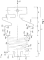
- Figure 1 is a plane view of an electrical terminal 1 according to a background example of the electrical terminal for terminating a wire.
- the electrical terminal 1 comprises an electrical contact segment 3 and a crimp segment 5 adjacent to it.
- the electrical contact segment 3 comprises an electrical contact 7 which can be of any shape and that is configured to receive a mating contact.
- the electrical contact can be any one of a male or female contact of various shapes, for instance spring contacts, beam contacts with or without fastening means like threads or mechanical fasteners.
- the crimp segment 5 comprises a first region 9 for receiving stripped conductors of a wire and a second region 11 for receiving a wire part with insulation.
- the crimp segment 5 furthermore comprises a transition region 13 between the first region 9 and the second region 11.
- the electrical terminal 1 in this embodiment furthermore comprises an electrical pin or socket contact element in region 15.
- the first, second and transition region 9, 11, 13 of the crimp segment 5 form the crimp barrel.
- the crimp segment 5 comprises a continuous base 17 that extends from the electrical contact segment 3 until the end of region 15.
- the first region 9 has opposing sidewalls 19a and 19b extending from the base 17.
- the second region 11 has opposing sidewalls 21a and 21b extending from the base 17.
- the transition region 13 has opposing sidewalls 23a and 23b extending from the base 17.
- the sidewalls 19a, 19b of the first region 7 each comprise a front cover end 25a and 25b at their extremity towards the electrical contact segment 3.
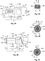
- Figures 2a and 2b illustrate a side view and a top view on an electrical connector 31 with the crimp segment 5 being crimped around a wire 33 to mechanically and electrically connect the wire 33 via the crimp barrel with the electrical contact 7 at the electrical contact segment 3.
- the electrical wire 33 comprises conductors 35 and an electrical insulation 37 around the conductors 35 as will be explained in more detail at a later stage.
- the electrical terminal 1 according to a background example is particularly advantageous for connectors 31 in which wires 33 with aluminium conductors 35 are crimped to a copper electrical terminal 1 forming a variant of the first background example.
- the crimp extends from the bare conductors 35 in the first region 9 up to the second region 11 where the insulation 37 is present and therefore provides the mechanical strength needed, in particular pull strength, even when aluminium is used as conductor material.
- the sidewalls 19a and 19b of the first region 9 are extending from the base 17 and are bent around the conductors 35 from which the insulation 7 (as shown in Figures 2a ) has been stripped off. By doing so the electrical and mechanical contact to the conductors 35 is achieved.
- the base and the folded sidewalls 17, 19a, 19b form a B-shape or a so-called F-crimp.
- the conductors 35 fill the complete volume, nevertheless situations may occur in which some voids are presents.
- the sidewalls 19a and 19b touch each other in area 39 thereby closing the volume 41 defined by the sidewalls 19a, 19b and the base 17, towards the exterior environment.
- the first region provides the electrical contact between the conductors 35 and the electrical terminal 1.
- the first region 9 can furthermore comprises one or more serrations 43 (in dotted lines in Figure 1 ), in particular sharp edged serrations, according to a second variant of the first background example.
- the serrations 43 are used to cut into the surface of the conductors 35 to destroy non conducting surface oxide layers that may be present or that may form at the moment of removing the insulation from the wire. The serrations 43 therefore ensure that even in the presence of such oxide layers a reliable electrical contact is achieved between the copper of the crimp segment 5 and the aluminium of the conductors 35.
- the non conducting surface layers on the surface of the aluminium conductors 35 can also be cracked using a higher compression degree during crimping compared to a copper - copper crimp.
- Figure 3b is a cut view in the area of the transition region 13.
- the wire 33 is positioned such on the crimp segment 5 that the transition from a region with bare stripped conductors 35 to that part of the wire with the insulation 37 positioned around the conductors 35 is in the transition region 13.
- the cut view shows an area where the conductors 35 are surrounded by the insulation 37. Furthermore, the cut view no longer shows a B shape of an F-crimp like in Figure 3a , but now the sidewalls 23a and 23b are folded around insulation 37 such that they overlap with their end region 45a and 45b along the circumferential direction. In Figure 3b the circumferential direction is indicated by the double arrow 47. The base 17 and the sidewalls 23a and 23b form a confined volume 49 around the wire 33. By wrapping the sidewalls 23a and 23b around the wire without forming the B shape any damage to the insulation 37 which otherwise could accidentally occur when using an F-crimp, can be prevented.
- Figures 2a and 2b also illustrate that at the intersection between the first region 9 and the transition region 13 the tunnel which is formed by the sidewalls 19a and 19b of the first region 9 and the sidewalls 23a and 23b of the transition region are positioned and arranged with each other such that the crimp barrel forms a tunnel with a confined volume.
- the risk of an exposure to moisture is reduced.
- cuts 51a and 51b or narrow slits are provided essentially perpendicular to the edges 53a and 53b of the sidewalls 19a and 19b, as shown in Figure 1 .
- cuts 51a and 51b are present on both sides, however according to further variants, such a cut can only be present on one side.
- bevelled or rounded edges 54a, 54b, 54c, 54d are provided at the side walls 19a/b and 23a/b in the transition between the first region 9 to the transition region 13 to facilitate the overlapping of sidewalls 23a/23b during the crimp process and the formation of the tapered funnel-shape 57.
- the shapes of these beveled edges can vary depending on the desired final shape.
- the dimensions of the sidewalls 23a and 23b and the length of the cuts 51a/b are chosen such that a funnel shape 57 is obtained in the transition region 13 when looking along the connector axis 55 (see Figure 1 ).
- the shorter diameter corresponds to the diameter of the bare stripped conductors 35 and the larger diameter of the funnel of 57 corresponds to the wire 33 with its insulation 37.
- Figure 3c shows a cut view along C-C in the second region 11.
- the sidewalls 21a and 21b together with the base 17 enclose the wire 33 with its insulation 37 without, however, having overlapping end regions 59a and 59b like in the transition region 13.
- the sidewalls 21a/b and the base 17 essentially form a ring around the wire 33.
- the ring can be slightly open thus presenting inspection holes 61a and 61b as shown in Figure 2b .
- the inspection holes can be used to verify that the insulation 37 is present in the second region 11 to prevent a false alignment of the wire 33 in the electrical terminal 1.
- the sidewalls 21a and 21b of the second region could also be folded around the wire 33 such that the end regions 59a and 59b touch each other as illustrated in Figure 3c .
- the sidewalls 21a and 21b of the second region 11 have a triangular shape dimensioned and positioned such with respect to each other that a joining region 63 can be observed that extends at least partially over the circumference of the wire 33 to thereby improve the stability of the crimp connection.
- the shape of the sidewalls 21a, 21b does not necessarily have to be triangular, any other suitable shape to allow a ring-shaped envelope around the wire 33 is possible.
- a cut 65 is present in the end region 45a of the sidewall 23a. This cut is essentially perpendicular to the edge of the end region 45a and enables the changeover from the overlapping crimp to the ring shaped crimp. Also here the sidewalls 23a/23b have bevelled or rounded edges 66a/66b to facilitate the overlapping. The shapes of these bevelled edges can vary depending on the desired final shape.
- the front cover ends 25a and 25b are bent such that in the crimped state, the opening at the extremity 67 of the tunnel defined by the base 17 and the sidewalls 19a and 19b is also closed to seal the interior of the tunnel from the environment to prevent the entry of moisture.
- the front cover ends 25a and 25b are bent around an axis 69 perpendicular to the connector axis 55 whereas the sidewalls 19a, 19b, 21/b and 23a/b are all bent around the direction parallel to the connector axis 55.
- Figure 4 illustrates an embodiment of an electrical terminal 71 according to the invention. Elements showing the same reference numerals as already used in the first background example and the figures 1 , 2a, 2b, and 3a to 3c will not be described in detail again but reference is made to their description above.
- the embodiment has a modified first region 73 in the crimp segment 5 compared to the connector in the first background example. As can be seen from Figure 4 one of the sidewalls 77a in the first region 73 is longer in the direction towards the electrical contact segment 3 than the opposing sidewall 77b.
- two front covers 79a and 79b are used to close the opening of the tunnel created by the folded sidewalls 77a and 77b of the first region 73, in the crimped state.
- the sidewall 77a is longer by an amount ⁇ , essentially corresponding to the thickness d of the front cover 79b.
- the front cover end 79a overlaps with the front cover end 79b to reliably seal away the internal volume of the tunnel from the exterior environment.
- voids inside the tunnel formed in the first region 9 or 73 and the transition region 13 or 75 can be filled with a corrosion protection means, like grease or similar inhibitator to even further reduce the risk of an exposure of the contact area to moisture.
- Figure 5 illustrates schematically a block diagram for fabricating an electrical connector as described above. The method can be realised in a complete automated way.
- Step 81 consists in placing a wire 33 on the electrical terminal 1 or 71 of the first or second embodiment.
- the bare stripped conductors 35 are positioned in the first region 9 or 73 and the part of the wire 33 with the insulation 37 is positioned in the second region 11 so that the transition between the two parts of the wire 33 is positioned in the transition region 13 or 75.
- the next step 83 consists in providing a corrosion preventing means, in particular grease in the first region 9 or 73 and the transition region 13 or 75.
- the third step 85 then consists in crimping the sidewalls 19a/b, 21a/b, 23a/b in the first region 9 or 75, the transition region 13 or 75 and the second regions 11 to thereby enclose the wire in the electrical terminal.
- the crimping in the first region 9 is carried out such that an F-crimp is achieved.
- the crimping of the transition region 13 or 75 is carried out such that the end portions 45a/b of the sidewalls 23a/b are overlapping each other in the circumferential direction 47.
- the crimping of the second region 11 is carried out such that the sidewalls are enveloping the insulation 37 without, however, having the overlapping ends.
- step 87 the front covers 25a/b are folded along an axis 69 perpendicular to the connector axis 55 to close the tunnel created by the crimped sidewalls.
Landscapes
- Engineering & Computer Science (AREA)
- Manufacturing & Machinery (AREA)
- Connections Effected By Soldering, Adhesion, Or Permanent Deformation (AREA)
- Manufacturing Of Electrical Connectors (AREA)
Claims (10)
- Elektrische Anschlussklemme (71) zum Abschließen eines Drahtes (33), wobei die elektrische Anschlussklemme umfasst:ein Quetschsegment (5) mit einer Basis (17) und gegenüberliegenden Seitenwänden (77a, 77b), die sich von der Basis (17) erstrecken und einen ersten Bereich (73) zum Aufnehmen abisolierter Leiter des Drahtes und einen zweiten Bereich (11) zum Aufnehmen eines Drahtteils mit Isolierung umfassen, wobei die gegenüberliegenden Seitenwände (77a, 77b) des ersten Bereiches (73) so konfiguriert und angeordnet sind, dass sie angepasst sind, um eine F-Quetschung zu bilden, wenn sie gequetscht werden,wobei das Quetschsegment (5) des Weiteren einen Übergangsbereich (75) zwischen dem ersten und dem zweiten Bereich (73, 11) umfasst, wobei die Seitenwände (77a, 77b) des Übergangsbereiches (75) so konfiguriert und angeordnet sind, dass sie angepasst sind, um den Draht mit Endbereichen (45a/b) der Seitenwände (77a, 77b) zu umhüllen, die einander in der Umfangsrichtung (47) überlappen, wenn sie gequetscht werden,wobei die Basis (17) und die Seitenwände (21a/b) des zweiten Bereiches (11) angepasst sind, um eine nicht überlappende offene oder geschlossene Ringform zu bilden, wenn sie gequetscht werden, und die Seitenwände (21a/b) des zweiten Bereiches (11) so konfiguriert und angeordnet sind, dass ein Verbindungsbereich überwacht werden kann, der sich wenigstens teilweise über den Umfang des Drahtes erstreckt, wenn er gequetscht wird,dadurch gekennzeichnet, dassdie Basis (17) und die Seitenwände (77a, 77b) des ersten Bereiches (73) und die Seitenwände (23a/b) des Übergangsbereiches (75) angepasst sind, um einen Tunnel zu bilden, wobei die Seitenwände des Tunnels ein begrenztes Volumen bilden, wenn sie gequetscht werden,der Endpunkt (67) des ersten Bereiches (73) gegenüber dem an den Übergangsbereich (75) angrenzenden Endpunkt des ersten Bereiches (73) ein oder mehrere biegbare vordere Abdeckungsenden (79a, 79b) umfasst, um den Tunnel an dem Endpunkt (67) zu verschließen, wobei die Enden der vorderen Abdeckungsenden (79a/b) angepasst sind, um sich zu überlappen, wenn sie gequetscht werden, wobei eine der Seitenwände (77a) des ersten Bereiches (73) länger ist als die andere Seitenwand (77b).
- Elektrische Anschlussklemme nach Anspruch 1, wobei die Seitenwände (21a/b) des zweiten Bereiches (11) angepasst sind, um wenigstens teilweise in dem an den Übergangsbereich (75) angrenzenden Bereich ebenfalls einen Tunnel zu bilden, wenn sie gequetscht werden.
- Elektrische Anschlussklemme nach Anspruch 1 oder 2, wobei der Übergangsbereich (75) angepasst ist, um eine Tunnelform zu haben, wenn er gequetscht wird.
- Elektrische Anschlussklemme nach einem der Ansprüche 1 bis 3, wobei eine der Seitenwände (77a) des ersten Bereiches (73) um die Dicke (d) des vorderen Abdeckungsendes (79b) länger ist als die andere Seitenwand (77b).
- Elektrische Anschlussklemme nach einem der Ansprüche 1 bis 4, wobei der Schnittpunkt zwischen den Seitenwänden (77a, 77b) des ersten Bereiches (73) und den Seitenwänden (23a/b) des Übergangsbereiches (75) einen Schnitt (51a/b) im Randbereich (53a/b) wenigstens auf einer Seite des Quetschsegments (5) darstellt.
- Elektrische Anschlussklemme nach einem der Ansprüche 1 bis 5, wobei der Schnittpunkt zwischen den Seitenwänden (23a/b) des Übergangsbereiches (75) und den Seitenwänden (21a/b) des zweiten Bereiches (11) einen Schnitt (65) im Randbereich wenigstens auf einer Seite des Quetschsegments (5) darstellt.
- Steckverbinder, der eine elektrische Anschlussklemme (71) nach einem der Ansprüche 1 bis 6 und einen Draht (33) im gequetschten Zustand umfasst, wobei der erste Bereich (73), der zweite Bereich (11) und der Übergangsbereich (75) des Quetschsegments (5) der elektrischen Anschlussklemme um den Draht (33) herum gefaltet werden, wobei sie eine Quetschhülse (5) bilden.
- Steckverbinder nach Anspruch 7, der des Weiteren ein Korrosionsverhinderungsmittel zum Auffüllen von Leerräumen innerhalb wenigstens des ersten Bereiches (73) und des Übergangsbereiches (75) der Quetschhülse (5) umfasst.
- Steckverbinder nach Anspruch 7 oder 8, wobei der Draht (33) ein Aluminiumdraht und die Quetschhülse (5) eine Kupferquetschhülse (5) ist.
- Verfahren zum Vorbereiten eines Steckverbinders nach einem der Ansprüche 7 bis 9, das die Schritte umfasst:a. Einführen eines Drahtes (33) in das Quetschsegment (5) der elektrischen Anschlussklemme (71) nach einem der Ansprüche 1 bis 6, so dass die blanken Leiter (35) in dem ersten Bereich (73) positioniert sind und der Drahtteil mit seiner Isolierung (37) in dem zweiten Bereich (11) positioniert ist, wobei der Übergang zwischen den beiden der Übergangsbereich (75) ist,b. Falten der Seitenwände (19a/19b) des ersten Bereiches (73), um dadurch eine F-Quetschung zu erhalten,c. Falten der Seitenwände (23a/b) des Übergangsbereiches (75), um dadurch die überlappende Quetschung in der Umfangsrichtung des Drahtes (33) zu erhalten,d. Falten der Seitenwände (21a/b) des zweiten Bereiches (11), um dadurch eine geschlossene oder offene nicht überlappende Ringform zu erhalten, so dass ein Verbindungsbereich (63) überwacht werden kann, der sich wenigstens teilweise über den Umfang des Drahtes erstreckt, unde. Falten der vorderen Abdeckungsenden (79a, 79b) in einer überlappenden Weise, um dadurch den Leiter (37) innerhalb des Tunnels abzudichten, der durch die Seitenwände (77a, 77b) des ersten Bereiches (73) und des Übergangsbereiches (75) gebildet wird.
Priority Applications (4)
| Application Number | Priority Date | Filing Date | Title |
|---|---|---|---|
| EP14290059.6A EP2919332B1 (de) | 2014-03-10 | 2014-03-10 | Elektrische Anschlussklemme und Verfahren zur Vorbereitung eines Steckverbinders mit solcher Anschlussklemme |
| US14/643,406 US9502785B2 (en) | 2014-03-10 | 2015-03-10 | Electrical terminal for terminating a wire |
| CN201510196518.1A CN104916934A (zh) | 2014-03-10 | 2015-03-10 | 用于端接电线的电端子 |
| JP2015046537A JP2015170603A (ja) | 2014-03-10 | 2015-03-10 | ワイヤを接続するための電気端子 |
Applications Claiming Priority (1)
| Application Number | Priority Date | Filing Date | Title |
|---|---|---|---|
| EP14290059.6A EP2919332B1 (de) | 2014-03-10 | 2014-03-10 | Elektrische Anschlussklemme und Verfahren zur Vorbereitung eines Steckverbinders mit solcher Anschlussklemme |
Publications (2)
| Publication Number | Publication Date |
|---|---|
| EP2919332A1 EP2919332A1 (de) | 2015-09-16 |
| EP2919332B1 true EP2919332B1 (de) | 2019-07-10 |
Family
ID=50391118
Family Applications (1)
| Application Number | Title | Priority Date | Filing Date |
|---|---|---|---|
| EP14290059.6A Active EP2919332B1 (de) | 2014-03-10 | 2014-03-10 | Elektrische Anschlussklemme und Verfahren zur Vorbereitung eines Steckverbinders mit solcher Anschlussklemme |
Country Status (4)
| Country | Link |
|---|---|
| US (1) | US9502785B2 (de) |
| EP (1) | EP2919332B1 (de) |
| JP (1) | JP2015170603A (de) |
| CN (1) | CN104916934A (de) |
Families Citing this family (18)
| Publication number | Priority date | Publication date | Assignee | Title |
|---|---|---|---|---|
| JP2018045762A (ja) * | 2016-09-12 | 2018-03-22 | 矢崎総業株式会社 | 圧着端子 |
| JP6506728B2 (ja) * | 2016-10-13 | 2019-04-24 | 矢崎総業株式会社 | 圧着端子および端子圧着装置 |
| EP3340388B1 (de) * | 2016-12-23 | 2024-07-24 | TE Connectivity Germany GmbH | Elektrischer abschirmungskontakt, vorzugsweise ein mini-koaxialabschirmungskontakt |
| US10312605B2 (en) * | 2017-02-10 | 2019-06-04 | Autonetworks Technologies, Ltd. | Terminal-equipped wire |
| JP6849548B2 (ja) * | 2017-07-04 | 2021-03-24 | 矢崎総業株式会社 | 端子付き電線 |
| JP6904147B2 (ja) * | 2017-08-01 | 2021-07-14 | 株式会社オートネットワーク技術研究所 | 端子付き電線 |
| JP7218045B2 (ja) * | 2017-10-16 | 2023-02-06 | 矢崎総業株式会社 | 端子付き電線 |
| KR102710699B1 (ko) * | 2018-01-12 | 2024-09-25 | 티이 커넥티버티 인디아 프라이빗 리미티드 | 와이어들을 연결하기 위한 크림프 |
| JP6901046B2 (ja) * | 2018-05-10 | 2021-07-14 | 株式会社オートネットワーク技術研究所 | 端子付き電線 |
| EP3588679B1 (de) * | 2018-06-29 | 2023-09-27 | TE Connectivity Germany GmbH | Crimp und verfahren zur herstellung eines crimps |
| US10992087B2 (en) | 2018-12-13 | 2021-04-27 | Amphenol Corporation | Contact member for electrical connector |
| JP7227607B2 (ja) * | 2019-04-11 | 2023-02-22 | 日本圧着端子製造株式会社 | 差動信号伝送ケーブル用コネクタのシェル構造 |
| JP7065061B2 (ja) * | 2019-08-29 | 2022-05-11 | 矢崎総業株式会社 | 電線付き端子及びその製造方法 |
| JP7212111B2 (ja) * | 2020-07-24 | 2023-01-24 | ティーイー コネクティビティ ジャーマニー ゲゼルシャフト ミット ベシュレンクテル ハフツンク | 電気フェルール、電気接続デバイス、および電気コネクタ |
| US11264735B1 (en) * | 2020-08-28 | 2022-03-01 | TE Connectivity Services Gmbh | Electrical terminal for terminating a wide size range of magnet wires |
| CN115133306A (zh) * | 2021-03-25 | 2022-09-30 | 泰科电子(上海)有限公司 | 旗型端子 |
| DE102021112505A1 (de) * | 2021-05-12 | 2022-11-17 | Te Connectivity Germany Gmbh | Crimpkontakt, Crimpverbindung und Verfahren zur Herstellung einer Crimpverbindung |
| CN114188792B (zh) * | 2021-12-21 | 2022-11-18 | 山东特瑞电力器材有限公司 | 一种可快速安装的楔形接续金具 |
Citations (2)
| Publication number | Priority date | Publication date | Assignee | Title |
|---|---|---|---|---|
| EP2151893A1 (de) * | 2008-08-07 | 2010-02-10 | Sumitomo Wiring Systems, Ltd. | Anschlussstück und Crimp-Verfahren |
| EP2239814A1 (de) * | 2009-04-07 | 2010-10-13 | Sumitomo Wiring Systems, Ltd. | Anschlusskontakt, Stecker und Montageverfahren |
Family Cites Families (23)
| Publication number | Priority date | Publication date | Assignee | Title |
|---|---|---|---|---|
| JPS574167U (de) * | 1980-06-09 | 1982-01-09 | ||
| US4641911A (en) | 1984-10-09 | 1987-02-10 | General Motors Corporation | Electrical connector having a funnel wrap wire crimp barrel |
| JPH078970U (ja) * | 1993-07-06 | 1995-02-07 | 住友電装株式会社 | ゴム栓付き端子圧着電線 |
| US5624273A (en) * | 1995-04-21 | 1997-04-29 | The Whitaker Corporation | Insulation displacement contact with strain relief |
| JP3472696B2 (ja) * | 1998-02-20 | 2003-12-02 | 矢崎総業株式会社 | 端 子 |
| EP2472675B1 (de) * | 2003-07-30 | 2020-09-30 | The Furukawa Electric Co., Ltd. | Struktur zum Crimpen von Anschlussklemmen und Verfahren zum Crimpen von Anschlussklemmen auf Aluminium-Elektrodraht |
| US7121903B2 (en) * | 2004-09-27 | 2006-10-17 | Yazaki Corporation | Terminal |
| JP4482823B2 (ja) * | 2005-12-26 | 2010-06-16 | 住友電装株式会社 | 端子金具 |
| JP4928800B2 (ja) * | 2006-02-17 | 2012-05-09 | 住友電装株式会社 | 端子金具 |
| JP2007250530A (ja) * | 2006-02-17 | 2007-09-27 | Auto Network Gijutsu Kenkyusho:Kk | 端子付電線 |
| CN101517814B (zh) * | 2006-09-25 | 2012-01-18 | 株式会社Lg化学 | 非水性电解质以及包含该电解质的电化学装置 |
| JP4499114B2 (ja) * | 2007-01-25 | 2010-07-07 | タイコエレクトロニクスジャパン合同会社 | 端子圧着方法、端子圧着装置、端子圧着構造及び電気コネクタ |
| JP5282462B2 (ja) * | 2008-07-07 | 2013-09-04 | 株式会社オートネットワーク技術研究所 | 端子付き電線 |
| JP2010055874A (ja) * | 2008-08-27 | 2010-03-11 | Sumitomo Wiring Syst Ltd | 端子金具と電線の接続構造 |
| EP2151892B1 (de) * | 2008-08-07 | 2017-05-03 | Sumitomo Wiring Systems, Ltd. | Anschlussstück und Anschlussverfahren dafür |
| JP5195230B2 (ja) * | 2008-09-26 | 2013-05-08 | 住友電装株式会社 | 端子金具付き電線 |
| JP5147648B2 (ja) * | 2008-11-07 | 2013-02-20 | 矢崎総業株式会社 | 圧着端子及び圧着端子における電線固定構造 |
| JP2011216253A (ja) * | 2010-03-31 | 2011-10-27 | Yazaki Corp | 圧着端子および圧着端子の電線に対する接続構造 |
| JP2012054107A (ja) * | 2010-09-01 | 2012-03-15 | Sumitomo Wiring Syst Ltd | 電線付き端子金具 |
| US8210884B2 (en) | 2010-10-18 | 2012-07-03 | Tyco Electronics Corporation | Electrical terminal for terminating a wire |
| JP5909345B2 (ja) * | 2011-11-11 | 2016-04-26 | 矢崎総業株式会社 | コネクタ端子 |
| EP2642598B1 (de) * | 2012-03-19 | 2017-09-13 | Yazaki Europe Ltd | Elektrisches Endgerät |
| DE202013001074U1 (de) * | 2013-02-01 | 2013-02-20 | Tyco Electronics Amp Gmbh | Elektrische Kontaktvorrichtung, insbesondere Crimpkontaktvorrichtung |
-
2014
- 2014-03-10 EP EP14290059.6A patent/EP2919332B1/de active Active
-
2015
- 2015-03-10 US US14/643,406 patent/US9502785B2/en not_active Expired - Fee Related
- 2015-03-10 JP JP2015046537A patent/JP2015170603A/ja active Pending
- 2015-03-10 CN CN201510196518.1A patent/CN104916934A/zh active Pending
Patent Citations (2)
| Publication number | Priority date | Publication date | Assignee | Title |
|---|---|---|---|---|
| EP2151893A1 (de) * | 2008-08-07 | 2010-02-10 | Sumitomo Wiring Systems, Ltd. | Anschlussstück und Crimp-Verfahren |
| EP2239814A1 (de) * | 2009-04-07 | 2010-10-13 | Sumitomo Wiring Systems, Ltd. | Anschlusskontakt, Stecker und Montageverfahren |
Also Published As
| Publication number | Publication date |
|---|---|
| US9502785B2 (en) | 2016-11-22 |
| CN104916934A (zh) | 2015-09-16 |
| US20150255886A1 (en) | 2015-09-10 |
| JP2015170603A (ja) | 2015-09-28 |
| EP2919332A1 (de) | 2015-09-16 |
Similar Documents
| Publication | Publication Date | Title |
|---|---|---|
| EP2919332B1 (de) | Elektrische Anschlussklemme und Verfahren zur Vorbereitung eines Steckverbinders mit solcher Anschlussklemme | |
| CA2814091C (en) | Electrical terminal for terminating a wire | |
| US9397410B2 (en) | Electrical terminal for terminating a wire | |
| EP2774223B1 (de) | Elektrischer kontakt mit rhombenförmigem riffelmuster | |
| US9306355B2 (en) | Connection method between braided shield layer of shiled wire and drain wire, and connection structure of the same | |
| US9502784B2 (en) | Terminal attached aluminum electric wire | |
| JP2010146739A (ja) | 電線接続スリーブ、電線接続スリーブの製造方法、電線接続スリーブが予め圧着されたリペア電線、および電線の接続方法 | |
| US20160204523A1 (en) | Conduction path and electrical wire | |
| KR20210023727A (ko) | 커넥터 및 케이블을 포함하는 조립체 | |
| KR20210023730A (ko) | 자동차 적용을 위한 커넥터 및 조립체 | |
| JP2011023245A (ja) | 接続部材及びそれを用いたコネクタ | |
| CN104272528A (zh) | 外部导体端子与电线的连接结构 | |
| US9972920B1 (en) | Terminal and terminal-equipped electric wire | |
| WO2015076177A1 (ja) | 端子付き電線及び端子付き電線の製造方法 | |
| CN105932430B (zh) | 套管、接触装置以及用于借助超声波来焊接细束状导线的方法 | |
| JP6912295B2 (ja) | 端子付き電線 | |
| JP6147232B2 (ja) | 端子付き電線の製造方法 | |
| CN107565253A (zh) | Rf线端连接器与同轴线缆的连接方法及其使用的内部端子 | |
| JP5895785B2 (ja) | 端子圧着構造、端子圧着構造の製造方法、及び外導体端子 | |
| EP4434120A1 (de) | Hülse mit hoher verformung und retention | |
| JP2005149972A (ja) | 同軸コネクタのカシメ方法 | |
| WO2015163102A1 (ja) | 圧着端子 |
Legal Events
| Date | Code | Title | Description |
|---|---|---|---|
| PUAI | Public reference made under article 153(3) epc to a published international application that has entered the european phase |
Free format text: ORIGINAL CODE: 0009012 |
|
| AK | Designated contracting states |
Kind code of ref document: A1 Designated state(s): AL AT BE BG CH CY CZ DE DK EE ES FI FR GB GR HR HU IE IS IT LI LT LU LV MC MK MT NL NO PL PT RO RS SE SI SK SM TR |
|
| AX | Request for extension of the european patent |
Extension state: BA ME |
|
| 17P | Request for examination filed |
Effective date: 20160216 |
|
| RBV | Designated contracting states (corrected) |
Designated state(s): AL AT BE BG CH CY CZ DE DK EE ES FI FR GB GR HR HU IE IS IT LI LT LU LV MC MK MT NL NO PL PT RO RS SE SI SK SM TR |
|
| STAA | Information on the status of an ep patent application or granted ep patent |
Free format text: STATUS: EXAMINATION IS IN PROGRESS |
|
| 17Q | First examination report despatched |
Effective date: 20170825 |
|
| GRAP | Despatch of communication of intention to grant a patent |
Free format text: ORIGINAL CODE: EPIDOSNIGR1 |
|
| STAA | Information on the status of an ep patent application or granted ep patent |
Free format text: STATUS: GRANT OF PATENT IS INTENDED |
|
| RIC1 | Information provided on ipc code assigned before grant |
Ipc: H01R 4/62 20060101ALN20181016BHEP Ipc: H01R 43/048 20060101AFI20181016BHEP Ipc: H01R 4/18 20060101ALI20181016BHEP Ipc: H01R 13/52 20060101ALN20181016BHEP |
|
| INTG | Intention to grant announced |
Effective date: 20181030 |
|
| GRAS | Grant fee paid |
Free format text: ORIGINAL CODE: EPIDOSNIGR3 |
|
| GRAA | (expected) grant |
Free format text: ORIGINAL CODE: 0009210 |
|
| STAA | Information on the status of an ep patent application or granted ep patent |
Free format text: STATUS: THE PATENT HAS BEEN GRANTED |
|
| AK | Designated contracting states |
Kind code of ref document: B1 Designated state(s): AL AT BE BG CH CY CZ DE DK EE ES FI FR GB GR HR HU IE IS IT LI LT LU LV MC MK MT NL NO PL PT RO RS SE SI SK SM TR |
|
| REG | Reference to a national code |
Ref country code: GB Ref legal event code: FG4D |
|
| REG | Reference to a national code |
Ref country code: CH Ref legal event code: EP Ref country code: AT Ref legal event code: REF Ref document number: 1154510 Country of ref document: AT Kind code of ref document: T Effective date: 20190715 |
|
| REG | Reference to a national code |
Ref country code: DE Ref legal event code: R096 Ref document number: 602014049766 Country of ref document: DE |
|
| REG | Reference to a national code |
Ref country code: IE Ref legal event code: FG4D |
|
| REG | Reference to a national code |
Ref country code: NL Ref legal event code: MP Effective date: 20190710 |
|
| REG | Reference to a national code |
Ref country code: LT Ref legal event code: MG4D |
|
| REG | Reference to a national code |
Ref country code: AT Ref legal event code: MK05 Ref document number: 1154510 Country of ref document: AT Kind code of ref document: T Effective date: 20190710 |
|
| PG25 | Lapsed in a contracting state [announced via postgrant information from national office to epo] |
Ref country code: HR Free format text: LAPSE BECAUSE OF FAILURE TO SUBMIT A TRANSLATION OF THE DESCRIPTION OR TO PAY THE FEE WITHIN THE PRESCRIBED TIME-LIMIT Effective date: 20190710 Ref country code: AT Free format text: LAPSE BECAUSE OF FAILURE TO SUBMIT A TRANSLATION OF THE DESCRIPTION OR TO PAY THE FEE WITHIN THE PRESCRIBED TIME-LIMIT Effective date: 20190710 Ref country code: SE Free format text: LAPSE BECAUSE OF FAILURE TO SUBMIT A TRANSLATION OF THE DESCRIPTION OR TO PAY THE FEE WITHIN THE PRESCRIBED TIME-LIMIT Effective date: 20190710 Ref country code: FI Free format text: LAPSE BECAUSE OF FAILURE TO SUBMIT A TRANSLATION OF THE DESCRIPTION OR TO PAY THE FEE WITHIN THE PRESCRIBED TIME-LIMIT Effective date: 20190710 Ref country code: NO Free format text: LAPSE BECAUSE OF FAILURE TO SUBMIT A TRANSLATION OF THE DESCRIPTION OR TO PAY THE FEE WITHIN THE PRESCRIBED TIME-LIMIT Effective date: 20191010 Ref country code: NL Free format text: LAPSE BECAUSE OF FAILURE TO SUBMIT A TRANSLATION OF THE DESCRIPTION OR TO PAY THE FEE WITHIN THE PRESCRIBED TIME-LIMIT Effective date: 20190710 Ref country code: BG Free format text: LAPSE BECAUSE OF FAILURE TO SUBMIT A TRANSLATION OF THE DESCRIPTION OR TO PAY THE FEE WITHIN THE PRESCRIBED TIME-LIMIT Effective date: 20191010 Ref country code: PT Free format text: LAPSE BECAUSE OF FAILURE TO SUBMIT A TRANSLATION OF THE DESCRIPTION OR TO PAY THE FEE WITHIN THE PRESCRIBED TIME-LIMIT Effective date: 20191111 Ref country code: LT Free format text: LAPSE BECAUSE OF FAILURE TO SUBMIT A TRANSLATION OF THE DESCRIPTION OR TO PAY THE FEE WITHIN THE PRESCRIBED TIME-LIMIT Effective date: 20190710 |
|
| PG25 | Lapsed in a contracting state [announced via postgrant information from national office to epo] |
Ref country code: RS Free format text: LAPSE BECAUSE OF FAILURE TO SUBMIT A TRANSLATION OF THE DESCRIPTION OR TO PAY THE FEE WITHIN THE PRESCRIBED TIME-LIMIT Effective date: 20190710 Ref country code: LV Free format text: LAPSE BECAUSE OF FAILURE TO SUBMIT A TRANSLATION OF THE DESCRIPTION OR TO PAY THE FEE WITHIN THE PRESCRIBED TIME-LIMIT Effective date: 20190710 Ref country code: AL Free format text: LAPSE BECAUSE OF FAILURE TO SUBMIT A TRANSLATION OF THE DESCRIPTION OR TO PAY THE FEE WITHIN THE PRESCRIBED TIME-LIMIT Effective date: 20190710 Ref country code: ES Free format text: LAPSE BECAUSE OF FAILURE TO SUBMIT A TRANSLATION OF THE DESCRIPTION OR TO PAY THE FEE WITHIN THE PRESCRIBED TIME-LIMIT Effective date: 20190710 Ref country code: GR Free format text: LAPSE BECAUSE OF FAILURE TO SUBMIT A TRANSLATION OF THE DESCRIPTION OR TO PAY THE FEE WITHIN THE PRESCRIBED TIME-LIMIT Effective date: 20191011 Ref country code: IS Free format text: LAPSE BECAUSE OF FAILURE TO SUBMIT A TRANSLATION OF THE DESCRIPTION OR TO PAY THE FEE WITHIN THE PRESCRIBED TIME-LIMIT Effective date: 20191110 |
|
| PG25 | Lapsed in a contracting state [announced via postgrant information from national office to epo] |
Ref country code: TR Free format text: LAPSE BECAUSE OF FAILURE TO SUBMIT A TRANSLATION OF THE DESCRIPTION OR TO PAY THE FEE WITHIN THE PRESCRIBED TIME-LIMIT Effective date: 20190710 |
|
| PG25 | Lapsed in a contracting state [announced via postgrant information from national office to epo] |
Ref country code: PL Free format text: LAPSE BECAUSE OF FAILURE TO SUBMIT A TRANSLATION OF THE DESCRIPTION OR TO PAY THE FEE WITHIN THE PRESCRIBED TIME-LIMIT Effective date: 20190710 Ref country code: DK Free format text: LAPSE BECAUSE OF FAILURE TO SUBMIT A TRANSLATION OF THE DESCRIPTION OR TO PAY THE FEE WITHIN THE PRESCRIBED TIME-LIMIT Effective date: 20190710 Ref country code: RO Free format text: LAPSE BECAUSE OF FAILURE TO SUBMIT A TRANSLATION OF THE DESCRIPTION OR TO PAY THE FEE WITHIN THE PRESCRIBED TIME-LIMIT Effective date: 20190710 Ref country code: EE Free format text: LAPSE BECAUSE OF FAILURE TO SUBMIT A TRANSLATION OF THE DESCRIPTION OR TO PAY THE FEE WITHIN THE PRESCRIBED TIME-LIMIT Effective date: 20190710 |
|
| PG25 | Lapsed in a contracting state [announced via postgrant information from national office to epo] |
Ref country code: SM Free format text: LAPSE BECAUSE OF FAILURE TO SUBMIT A TRANSLATION OF THE DESCRIPTION OR TO PAY THE FEE WITHIN THE PRESCRIBED TIME-LIMIT Effective date: 20190710 Ref country code: IS Free format text: LAPSE BECAUSE OF FAILURE TO SUBMIT A TRANSLATION OF THE DESCRIPTION OR TO PAY THE FEE WITHIN THE PRESCRIBED TIME-LIMIT Effective date: 20200224 Ref country code: CZ Free format text: LAPSE BECAUSE OF FAILURE TO SUBMIT A TRANSLATION OF THE DESCRIPTION OR TO PAY THE FEE WITHIN THE PRESCRIBED TIME-LIMIT Effective date: 20190710 Ref country code: SK Free format text: LAPSE BECAUSE OF FAILURE TO SUBMIT A TRANSLATION OF THE DESCRIPTION OR TO PAY THE FEE WITHIN THE PRESCRIBED TIME-LIMIT Effective date: 20190710 |
|
| REG | Reference to a national code |
Ref country code: DE Ref legal event code: R097 Ref document number: 602014049766 Country of ref document: DE |
|
| PLBE | No opposition filed within time limit |
Free format text: ORIGINAL CODE: 0009261 |
|
| STAA | Information on the status of an ep patent application or granted ep patent |
Free format text: STATUS: NO OPPOSITION FILED WITHIN TIME LIMIT |
|
| PG2D | Information on lapse in contracting state deleted |
Ref country code: IS |
|
| 26N | No opposition filed |
Effective date: 20200603 |
|
| PG25 | Lapsed in a contracting state [announced via postgrant information from national office to epo] |
Ref country code: SI Free format text: LAPSE BECAUSE OF FAILURE TO SUBMIT A TRANSLATION OF THE DESCRIPTION OR TO PAY THE FEE WITHIN THE PRESCRIBED TIME-LIMIT Effective date: 20190710 |
|
| PG25 | Lapsed in a contracting state [announced via postgrant information from national office to epo] |
Ref country code: MC Free format text: LAPSE BECAUSE OF FAILURE TO SUBMIT A TRANSLATION OF THE DESCRIPTION OR TO PAY THE FEE WITHIN THE PRESCRIBED TIME-LIMIT Effective date: 20190710 |
|
| REG | Reference to a national code |
Ref country code: CH Ref legal event code: PL |
|
| REG | Reference to a national code |
Ref country code: BE Ref legal event code: MM Effective date: 20200331 |
|
| PG25 | Lapsed in a contracting state [announced via postgrant information from national office to epo] |
Ref country code: LU Free format text: LAPSE BECAUSE OF NON-PAYMENT OF DUE FEES Effective date: 20200310 |
|
| PG25 | Lapsed in a contracting state [announced via postgrant information from national office to epo] |
Ref country code: LI Free format text: LAPSE BECAUSE OF NON-PAYMENT OF DUE FEES Effective date: 20200331 Ref country code: IE Free format text: LAPSE BECAUSE OF NON-PAYMENT OF DUE FEES Effective date: 20200310 Ref country code: CH Free format text: LAPSE BECAUSE OF NON-PAYMENT OF DUE FEES Effective date: 20200331 |
|
| PG25 | Lapsed in a contracting state [announced via postgrant information from national office to epo] |
Ref country code: BE Free format text: LAPSE BECAUSE OF NON-PAYMENT OF DUE FEES Effective date: 20200331 |
|
| GBPC | Gb: european patent ceased through non-payment of renewal fee |
Effective date: 20200310 |
|
| PG25 | Lapsed in a contracting state [announced via postgrant information from national office to epo] |
Ref country code: GB Free format text: LAPSE BECAUSE OF NON-PAYMENT OF DUE FEES Effective date: 20200310 |
|
| PG25 | Lapsed in a contracting state [announced via postgrant information from national office to epo] |
Ref country code: MT Free format text: LAPSE BECAUSE OF FAILURE TO SUBMIT A TRANSLATION OF THE DESCRIPTION OR TO PAY THE FEE WITHIN THE PRESCRIBED TIME-LIMIT Effective date: 20190710 Ref country code: CY Free format text: LAPSE BECAUSE OF FAILURE TO SUBMIT A TRANSLATION OF THE DESCRIPTION OR TO PAY THE FEE WITHIN THE PRESCRIBED TIME-LIMIT Effective date: 20190710 |
|
| PG25 | Lapsed in a contracting state [announced via postgrant information from national office to epo] |
Ref country code: MK Free format text: LAPSE BECAUSE OF FAILURE TO SUBMIT A TRANSLATION OF THE DESCRIPTION OR TO PAY THE FEE WITHIN THE PRESCRIBED TIME-LIMIT Effective date: 20190710 |
|
| PGFP | Annual fee paid to national office [announced via postgrant information from national office to epo] |
Ref country code: DE Payment date: 20231229 Year of fee payment: 11 |
|
| PGFP | Annual fee paid to national office [announced via postgrant information from national office to epo] |
Ref country code: IT Payment date: 20240212 Year of fee payment: 11 Ref country code: FR Payment date: 20240103 Year of fee payment: 11 |