EP2918741A1 - Return flow block - Google Patents
Return flow block Download PDFInfo
- Publication number
- EP2918741A1 EP2918741A1 EP15000357.2A EP15000357A EP2918741A1 EP 2918741 A1 EP2918741 A1 EP 2918741A1 EP 15000357 A EP15000357 A EP 15000357A EP 2918741 A1 EP2918741 A1 EP 2918741A1
- Authority
- EP
- European Patent Office
- Prior art keywords
- jet nozzle
- opening
- nozzle
- jet
- membrane
- Prior art date
- Legal status (The legal status is an assumption and is not a legal conclusion. Google has not performed a legal analysis and makes no representation as to the accuracy of the status listed.)
- Granted
Links
- 230000004888 barrier function Effects 0.000 claims abstract description 87
- 238000003780 insertion Methods 0.000 claims abstract description 54
- 230000037431 insertion Effects 0.000 claims abstract description 54
- 239000012528 membrane Substances 0.000 claims abstract description 41
- 239000007788 liquid Substances 0.000 claims abstract description 21
- XLYOFNOQVPJJNP-UHFFFAOYSA-N water Substances O XLYOFNOQVPJJNP-UHFFFAOYSA-N 0.000 claims description 68
- 238000010992 reflux Methods 0.000 claims description 40
- 238000002347 injection Methods 0.000 claims description 8
- 239000007924 injection Substances 0.000 claims description 8
- 230000002093 peripheral effect Effects 0.000 claims description 7
- 238000005507 spraying Methods 0.000 claims description 3
- 239000000463 material Substances 0.000 claims description 2
- 239000007921 spray Substances 0.000 abstract description 20
- 210000004379 membrane Anatomy 0.000 description 28
- 210000002445 nipple Anatomy 0.000 description 8
- 125000006850 spacer group Chemical group 0.000 description 8
- 238000011144 upstream manufacturing Methods 0.000 description 7
- 238000009423 ventilation Methods 0.000 description 7
- 101100493706 Caenorhabditis elegans bath-38 gene Proteins 0.000 description 6
- 239000003651 drinking water Substances 0.000 description 5
- 235000020188 drinking water Nutrition 0.000 description 5
- 235000008733 Citrus aurantifolia Nutrition 0.000 description 4
- 235000011941 Tilia x europaea Nutrition 0.000 description 4
- 239000000919 ceramic Substances 0.000 description 4
- 238000001704 evaporation Methods 0.000 description 4
- 230000008020 evaporation Effects 0.000 description 4
- 239000004571 lime Substances 0.000 description 4
- 244000052616 bacterial pathogen Species 0.000 description 3
- 238000005422 blasting Methods 0.000 description 3
- 238000013461 design Methods 0.000 description 3
- 238000011161 development Methods 0.000 description 3
- 230000018109 developmental process Effects 0.000 description 3
- 208000004434 Calcinosis Diseases 0.000 description 2
- 238000003287 bathing Methods 0.000 description 2
- 238000004140 cleaning Methods 0.000 description 2
- 239000013013 elastic material Substances 0.000 description 2
- 230000001771 impaired effect Effects 0.000 description 2
- 238000004519 manufacturing process Methods 0.000 description 2
- 238000005192 partition Methods 0.000 description 2
- 230000001717 pathogenic effect Effects 0.000 description 2
- 241001295925 Gegenes Species 0.000 description 1
- 229910000831 Steel Inorganic materials 0.000 description 1
- 230000002308 calcification Effects 0.000 description 1
- 238000006243 chemical reaction Methods 0.000 description 1
- 238000011109 contamination Methods 0.000 description 1
- 230000003670 easy-to-clean Effects 0.000 description 1
- 230000000694 effects Effects 0.000 description 1
- KEUKAQNPUBYCIC-UHFFFAOYSA-N ethaneperoxoic acid;hydrogen peroxide Chemical compound OO.CC(=O)OO KEUKAQNPUBYCIC-UHFFFAOYSA-N 0.000 description 1
- 239000012530 fluid Substances 0.000 description 1
- 239000004615 ingredient Substances 0.000 description 1
- 238000012423 maintenance Methods 0.000 description 1
- 238000000034 method Methods 0.000 description 1
- 239000002245 particle Substances 0.000 description 1
- 238000003825 pressing Methods 0.000 description 1
- 230000005855 radiation Effects 0.000 description 1
- 239000010959 steel Substances 0.000 description 1
- 239000008399 tap water Substances 0.000 description 1
- 235000020679 tap water Nutrition 0.000 description 1
- 230000007704 transition Effects 0.000 description 1
Images


Classifications
-
- E—FIXED CONSTRUCTIONS
- E03—WATER SUPPLY; SEWERAGE
- E03D—WATER-CLOSETS OR URINALS WITH FLUSHING DEVICES; FLUSHING VALVES THEREFOR
- E03D9/00—Sanitary or other accessories for lavatories ; Devices for cleaning or disinfecting the toilet room or the toilet bowl; Devices for eliminating smells
- E03D9/08—Devices in the bowl producing upwardly-directed sprays; Modifications of the bowl for use with such devices ; Bidets; Combinations of bowls with urinals or bidets; Hot-air or other devices mounted in or on the bowl, urinal or bidet for cleaning or disinfecting
-
- E—FIXED CONSTRUCTIONS
- E03—WATER SUPPLY; SEWERAGE
- E03C—DOMESTIC PLUMBING INSTALLATIONS FOR FRESH WATER OR WASTE WATER; SINKS
- E03C1/00—Domestic plumbing installations for fresh water or waste water; Sinks
- E03C1/02—Plumbing installations for fresh water
- E03C1/10—Devices for preventing contamination of drinking-water pipes, e.g. means for aerating self-closing flushing valves
- E03C1/102—Devices for preventing contamination of drinking-water pipes, e.g. means for aerating self-closing flushing valves using an air gap device
Landscapes
- Health & Medical Sciences (AREA)
- Public Health (AREA)
- Life Sciences & Earth Sciences (AREA)
- Engineering & Computer Science (AREA)
- Hydrology & Water Resources (AREA)
- Water Supply & Treatment (AREA)
- Molecular Biology (AREA)
- Epidemiology (AREA)
- Nozzles (AREA)
- Domestic Plumbing Installations (AREA)
- Bathtubs, Showers, And Their Attachments (AREA)
- Devices For Medical Bathing And Washing (AREA)
Abstract
Die Anmeldung betrifft eine Rückfluss-Sperre (1), die eine, mit einem Zulauf (3) verbindbare Strahldüse (4) und ein Einfangteil (5) hat, das den von der Strahldüse (4) über eine freie Strahlstrecke (6) kommenden Flüssigkeitsstrahl einzufangen hat und das mit einem Ablauf (7) verbindbar beziehungsweise verbunden ist, sowie mit einem unterhalb der freien Strahlstrecke (6) angeordneten Auslauf (8), welcher Auslauf (8) eine vom Einfangteil (5) nicht eingefangene Flüssigkeits-Teilmenge auszuleiten hat. Dabei ist die Strahldüse (4) in der Rückfluss-Sperre (1, 100) verschieblich geführt und von einer Bereitschaftsstellung in eine Spritzstellung verschiebbar ist, in welcher Spritzstellung die Strahldüse (4) mit ihrem eine Düsenöffnung (21) umgrenzenden Düsenabschnitt eine Durchstecköffnung (36) durchstößt, die in einer elastischen Membran (35) vorgesehen oder in Bereitschaftsstellung von einer Klappe verschlossen ist.The application relates to a backflow barrier (1), which has a, with an inlet (3) connectable jet nozzle (4) and a catching part (5), the of the jet nozzle (4) via a free jet path (6) coming liquid jet and that is connectable or connected with a drain (7), and with an outlet (8) arranged below the free jet path (6), which outlet (8) has to discharge a liquid subset not captured by the capture part (5). In this case, the jet nozzle (4) is displaceably guided in the backflow barrier (1, 100) and is displaceable from a standby position into a spray position, in which spray position the jet nozzle (4) with its nozzle section delimiting a nozzle opening (21) has an insertion opening (36 ), which is provided in an elastic membrane (35) or closed in the ready position by a flap.
Description
Die Erfindung betrifft eine Rückfluss-Sperre, die eine mit, mit einem Zulauf verbindbare Strahldüse und ein Einfangteil hat, das den von der Strahldüse über eine freie Strahl-Strecke kommenden Flüssigkeitsstrahl einzufangen hat und das mit einem Ablauf verbindbar bzw. verbunden ist, sowie mit einem unterhalb der freien Strahlstrecke angeordneten Auslauf, welcher Auslauf eine vom Einfangteil nicht eingefangene Flüssigkeits-Teilmenge auszuleiten hat.The invention relates to a backflow barrier which has a jet nozzle which can be connected to an inlet and a catching part which has to capture the liquid jet coming from the jet nozzle via a free jet path and which can be connected or connected to a drain, and with an outlet arranged below the free jet path, which outlet has to discharge a liquid subset not captured by the catching part.
Unterduschen in Klosetts werden mit Wasser aus dem allgemeinen Versorgungsnetz betrieben. Zum Schutz des allgemeinen Versorgungsnetzes, aus dem auch die in die Klosetts integrierten Unterduschen gespeist werden, gegen das Eindringen pathogener Keime ist eine dauernd wirkende Rückfluss-Sperre erforderlich. Befindet sich die Spritzdüse einer Unterdusche im Bereich des Beckenrandes einer Klosettschüssel, so muss damit gerechnet werden, dass die Düsenöffnung dieser Spritzdüse mit Schmutzwasser oder Exkrementenanteilen verunreinigt wird. Da bei einer direkten Verbindung mit der Wasserversorgung die Gefahr besteht, dass dadurch unter Umständen pathogene Keime über das Absperrventil in das Trinkwasserversorgungsnetz eindringen können, sehen die nationalen und die europäischen Normen sowie die Bedingungen der Wasserversorgungsgesellschaften eine sogenannte mittelbare Verbindung zwischen dem allgemeinen Versorgungsnetz und dem Klosett vor, wenn diese Klosetts, gegebenenfalls auch nachträglich im WC-Sitz, mit einer Unterdusche ausgerüstet sind.Showers in toilets are operated with water from the general supply network. To protect the general supply network, from which the integrated into the toilets Unterduschen be fed, against the ingress of pathogenic germs, a permanent-acting backflow barrier is required. If the spray nozzle of a sub-shower is located in the area of the edge of a toilet bowl bowl, it must be expected that the nozzle opening of this spray nozzle becomes contaminated with dirty water or excrement particles. Since there is a risk in a direct connection with the water supply, that may result in pathogenic germs via the shut-off valve in the Drinking water supply network, provide the national and European standards and the conditions of the water companies before a so-called indirect connection between the general supply network and the toilet, if these toilets, possibly also in the toilet seat, are equipped with a sub-shower.
Auch ist es bereits bekannt, den Badewanneneinlauf mit dem Badewannenauslauf in einer wannenbodenseitigen Wannenöffnung zusammenzulegen. Da damit auch der Badewanneneinlauf unterhalb der Wasseroberfläche angeordnet ist, kann das Badewasser spritzwasserfrei und geräuscharm in die Badewanne einlaufen. Da das auf das einlaufende Wasser und die Wannenöffnung drückende, bereits in der Badewanne befindliche Badewasser jedoch die Gefahr beinhaltet, dass verunreinigtes Bade- oder Brauchwasser in das Wasserversorgungsnetz einströmt, ist auch bei diesem Anwendungsbeispiel eine wirkungsvolle Einlaufsicherung und Rückfluss-Sperre unbedingt sicherzustellen.Also, it is already known to combine the bath inlet with the bath spout in a tub bottom side trough opening. Since the bathtub inlet is thus arranged below the water surface, the bath water can run into the bathtub free of splash water and with little noise. However, since the bathing water present on the incoming water and the bath opening, already in the bathtub, involves the risk that contaminated bath water or service water flows into the water supply network, an effective inlet safety device and backflow barrier must also be ensured in this application example.
Aus der
Bei diesen, in den Normen auch als "freier Auslauf mit Injektor" bezeichneten Rückfluss-Sperren wird die Druckenergie des vom Versorgungsnetz zuströmenden Wassers im Bereich der Strahldüse in kinetische Energie umgewandelt, um den Wasserstrahl auf der kurzen freien Strahlstrecke mit der Atmosphäre in Verbindung zu bringen und um anschließend die kinetische Energie des Wasserstrahles im Bereich des auch als Diffusor bezeichneten Einfangteiles erneut zumindest teilweise in Druckenergie umzuwandeln, die beispielsweise für den Reinigungsstrahl der Unterduschen benötigt wird. Um die Umwandlung der Druckenergie in kinetische Energie und anschließend auch umgekehrt ohne größere Energieverluste bewerkstelligen zu können, und um im Bereich der freien Strahlstrecke einen homogenen und ruhigen Wasserstrahl zu erzeugen, sind die Strahldüse und das Einfangteil aufeinander und auf die spezifischen Verhältnisse des jeweiligen Versorgungsnetzes anzupassen. Es ist ein Nachteil, dass die vorbekannten Rückfluss-Sperren zwar im Hinblick auf die in einem bestimmten Versorgungsnetz vorherrschenden Verhältnisse optimiert sind, - dass aber diese Rückfluss-Sperren unter davon abweichenden Bedingungen eventuell keine optimale Funktion gewährleisten. Dabei ist stets wirkungsvoll sicherzustellen, dass das Leitungsnetz nicht mit Schmutzwasser kontaminiert wird.These, also referred to in the standards as "free-flow with injector" return barriers, the pressure energy of the inflowing water from the supply network in the jet nozzle is converted into kinetic energy to bring the water jet on the short free jet distance to the atmosphere in combination and subsequently to at least partially convert the kinetic energy of the water jet in the area of the trapping part, also referred to as a diffuser, into pressure energy which is required, for example, for the cleaning jet of the sub-showers. In order to be able to accomplish the conversion of the pressure energy into kinetic energy and subsequently vice versa without major energy losses, and in order to produce a homogeneous and smooth water jet in the area of the free jet path, the jet nozzle and the capture part are to be adapted to each other and to the specific conditions of the respective supply network , It is a disadvantage that the prior art backflow barriers are indeed optimized in view of the prevailing conditions in a particular supply network, but that these backflow barriers may not provide optimal performance under different conditions. It is always effective to ensure that the pipe network is not contaminated with dirty water.
Die optimierte Abstimmung zwischen der Strahldüse und dem Einfangteil kann beeinträchtigt werden, wenn insbesondere an der Düsenöffnung des Einfangteiles sich Schmutz- oder Kalkablagerungen bilden. Solche Kalkablagerungen sind möglich, wenn die an der Düsenöffnung der Strahldüse verbleibenden Wassertropfen verdunsten und ein ursprünglich im Wasser enthaltener Kalkrest zurückbleibt.The optimized coordination between the jet nozzle and the catching part can be impaired if, in particular, dirt or calcium deposits form on the nozzle opening of the catching part. Such lime deposits are possible if the water droplets remaining at the nozzle opening of the jet nozzle evaporate and a lime residue originally contained in the water remains behind.
Es besteht daher die Aufgabe, eine Rückfluss-Sperre der eingangs erwähnten Art zu schaffen, die vergleichsweise wartungsarm betrieben werden kann und bei der insbesondere das Risiko von Kalkablagerungen vermindert ist.It is therefore an object to provide a backflow barrier of the type mentioned above, which can be operated relatively low maintenance and in particular the risk of limescale is reduced.
Die erfindungsgemäße Lösung dieser Aufgabe besteht bei der Rückfluss-Sperre der eingangs erwähnten Art insbesondere darin, dass die Strahldüse in der Rückfluss-Sperre verschieblich geführt und von einer Bereitschaftsstellung in eine Spritzstellung verschiebbar ist, in welcher Spritzstellung die Strahldüse mit ihrem eine Düsenöffnung umgrenzenden Düsenabschnitt eine Durchstecköffnung durchstößt, die in einer elastischen Membran vorgesehen oder in Bereitschaftsstellung von einer Klappe verschlossen ist.The achievement of this object is in the backflow barrier of the type mentioned in particular in that the jet nozzle is displaceably guided in the backflow barrier and displaced from a standby position into a spraying position, in which injection position the jet nozzle with its nozzle orifice delimiting a nozzle section Through opening pierces, which is provided in an elastic membrane or closed in the ready position by a flap.
Bei dieser, gemäß dem Erfindungsvorschlag konstruierten Rückfluss-Sperre ist die Strahldüse in der Rückfluss-Sperre verschieblich geführt und von einer Bereitschaftsstellung in eine Spritzstellung verschiebbar. Während die Strahldüse in der Spritzstellung mit ihrem eine Düsenöffnung umgrenzenden Düsenabschnitt eine Durchstecköffnung durchstößt, die in einer elastischen Membran vorgesehen oder in Bereitschaftsstellung von einer Klappe verschlossen ist, ist die Strahldüse in der Bereitschaftsstellung von der elastischen Membran oder der Klappe verdeckt, so dass eine zu Kalkablagerungen führende Verdunstung vermindert auftritt.In this, constructed in accordance with the proposed invention reflux barrier, the jet nozzle is guided displaceably in the return flow barrier and displaceable from a standby position into a spray position. While the jet nozzle in the spray position with its nozzle opening delimiting nozzle portion pierces a through-hole provided in an elastic membrane or in the standby position is closed by a flap, the jet nozzle is concealed in the standby position of the elastic membrane or the flap, so that one Lime deposits leading to reduced evaporation occurs.
Um die Strahldüse in der Rückfluss-Sperre verschieblich führen zu können, und um eine solche Rückfluss-Sperre auf möglichst einfache Weise herstellen zu können, sieht eine bevorzugte Ausführungsform gemäß der Erfindung vor, dass eine hülsenförmige Strahldüsen-Aufnahme vorgesehen ist, in welcher die Strahldüse verschieblich geführt ist, und dass die Strahldüsen-Aufnahme über wenigstens einen Verbindungssteg mit dem Einfangteil verbunden ist.In order to be able to displaceably guide the jet nozzle in the backflow barrier and to be able to produce such a backflow barrier in the simplest possible way, a preferred embodiment according to the invention provides that a sleeve-shaped jet nozzle receptacle is provided, in which the jet nozzle slidably guided, and that the jet nozzle receiving over at least one connecting web connected to the trapping part.
Es hat sich gezeigt, dass der die Düsenöffnung umgrenzende Randbereich möglichst scharfkantig ausgestaltet sein sollte, um einen nicht-spritzenden Flüssigkeitsstrahl aus der Strahldüse austreten zu lassen. Während des Herstellungsprozesses besteht jedoch die Gefahr, dass diese scharfkantige Ausgestaltung des die Düsenöffnung umgrenzenden Randbereiches durch äußere Einflüsse beeinträchtigt wird. Um solchen Beschädigungen des scharfkantigen Randbereiches entgegenzuwirken, sieht eine bevorzugte Ausführungsform gemäß der Erfindung vor, dass an die Strahldüse ein ringförmiger Vorsprung einstückig angeformt ist, welcher die Düsenöffnung umgibt.It has been shown that the edge region delimiting the nozzle opening should be designed as sharp-edged as possible in order to allow a non-squirting liquid jet to emerge from the jet nozzle. During the manufacturing process, however, there is a risk that this sharp-edged configuration of the edge region delimiting the nozzle opening is impaired by external influences. To counteract such damage to the sharp-edged edge region, a preferred embodiment according to the invention provides that an annular projection is integrally formed on the jet nozzle, which surrounds the nozzle opening.
Die Erzeugung eines energiereichen und nicht-spritzenden Flüssigkeitsstrahles in der Strahldüse wird begünstigt, wenn der die Düsenöffnung der Strahldüse umgrenzende Öffnungsrand scharfkantig und dazu fasen- und rundungslos ausgestaltet ist.The generation of a high-energy and non-splashing liquid jet in the jet nozzle is favored when the nozzle opening of the jet nozzle delimiting opening edge is sharp-edged and designed to be chamfered and without rounding.
Dabei sieht ein bevorzugtes Ausführungsbeispiel gemäß der Erfindung vor, dass dieser Öffnungsrand der Düsenöffnung einen Kantengrad kleiner 0,1 mm oder größer minus 0,1 mm hat.In this case, a preferred embodiment according to the invention provides that this opening edge of the nozzle opening has an edge degree of less than 0.1 mm or greater minus 0.1 mm.
Ein optimierter Austritt des Flüssigkeitsstrahles aus der Strahldüse wird begünstigt, wenn die Strahldüse im Bereich ihrer Düsenöffnung einen hohlzylindrischen lichten Querschnitt aufweist.An optimized outlet of the liquid jet from the jet nozzle is favored when the jet nozzle has a hollow cylindrical clear cross-section in the region of its nozzle opening.
Um verdunstungsbedingten Kalkablagerungen im Bereich der Düsenöffnung der Strahldüse entgegenzuwirken, sieht eine bevorzugte Weiterbildung gemäß der Erfindung vor, dass die Strahldüse im Bereich der Düsenöffnung in der Bereitschaftsstellung in einem Wasserbad angeordnet oder von Wasser umgeben ist, und dass dazu die Klappe oder die Membran die Durchstecköffnung in der Bereitschaftsstellung vorzugsweise flüssigkeitsdicht verschließt. Da die Strahldüse mit ihrer Düsenöffnung in der Bereitschaftsstellung in einem Wasserbad angeordnet oder von Wasser umgeben ist, wird verdunstungsbedingten Kalkablagerungen an der Düsenöffnung der Strahldüse wirkungsvoll entgegengewirkt. Die Strahldüse wird erst dann aus dem Wasserbad oder aus dem in Bereitschaftsstellung umgebenden Wasser vorgeschoben, wenn die Strahldüse in der Spritzstellung die Durchstecköffnung durchstößt, die in der elastischen Membran vorgesehen oder während der Bereitschaftsstellung durch eine Klappe verschlossen ist.In order to counteract evaporation-induced lime deposits in the region of the nozzle opening of the jet nozzle, a preferred development according to the invention provides that the jet nozzle is arranged in the region of the nozzle opening in the standby position in a water bath or surrounded by water, and in that the flap or the membrane preferably closes the insertion opening in the ready position in a liquid-tight manner. Since the jet nozzle is arranged with its nozzle opening in the standby position in a water bath or surrounded by water, evaporation-related limescale deposits on the nozzle opening of the jet nozzle is effectively counteracted. The jet nozzle is only advanced from the water bath or from the water surrounding in the ready position, when the jet nozzle in the spray position pierces the insertion opening, which is provided in the elastic membrane or closed during the standby position by a flap.
Die Schiebebewegung der Strahldüse zwischen der Bereitschaftsstellung und der Spritzstellung ist mit Hilfe eines motorischen Antriebs möglich. Eine besonders einfache und deshalb bevorzugte Ausführungsform gemäß der Erfindung sieht jedoch vor, dass die Strahldüse von der Bereitschaftsstellung gegen eine Rückstellkraft in die Spritzstellung verschiebbar ist.The sliding movement of the jet nozzle between the ready position and the injection position is possible by means of a motor drive. However, a particularly simple and therefore preferred embodiment according to the invention provides that the jet nozzle is displaceable from the ready position against a restoring force in the injection position.
Eine bevorzuge Weiterbildung gemäß der Erfindung sieht statt eines motorischen Antriebes vor, dass die Strahldüse unter dem Druck der durchströmenden Flüssigkeit verschiebbar ist.A preferred development according to the invention provides, instead of a motor drive, that the jet nozzle is displaceable under the pressure of the liquid flowing through.
Dabei kann als Rückstellkraft zumindest eine Rückstellfeder vorgesehen sein, insbesondere wenn die Durchstecköffnung während der Bereitschaftsstellung durch eine Klappe verschlossen werden soll. Eine besonders einfache und deshalb bevorzugte Ausführungsform gemäß der Erfindung sieht jedoch vor, dass als Rückstellkraft die vorzugsweise auf die Strahldüse einwirkende Eigenelastizität des für die Membran verwendeten Materials dient.In this case, at least one restoring spring can be provided as restoring force, in particular if the insertion opening is to be closed by a flap during the standby position. However, a particularly simple and therefore preferred embodiment according to the invention provides that the restoring force is the inherent elasticity of the material used for the membrane, which is preferably applied to the jet nozzle.
Um auf die in der Strahldüsen-Aufnahme verschieblich geführte Strahldüse eine ausreichende Rückstellkraft ausüben zu können, ist es vorteilhaft, wenn die Strahldüse in eine topfförmig ausgebildete.Membran vorsteht, die an einem Topfboden ihrer Topfform die Durchstecköffnung trägt, und wenn sich der dem Topfboden abgewandte Umfangsrand der Membran gummielastisch an der Strahldüse abstützt.In order to be able to exert sufficient restoring force on the jet nozzle displaceably guided in the jet nozzle receptacle, it is advantageous if the jet nozzle protrudes into a pot-shaped membrane which carries the push-through opening on a pot base of its pot shape, and if it faces away from the bottom of the pot The peripheral edge of the membrane is elastically supported on the jet nozzle.
Eine bevorzugte Ausführungsform gemäß der Erfindung sieht vor, dass die Membran im Bereich des Topfbodens ihrer Topfform die Strahldüsen-Aufnahme im Bereich einer in der Führungswand vorgesehenen Öffnung abdichtet und dass die Membran am Umfang ihrer Topfform wenigstens eine Durchflussöffnung aufweist, welche den Innenraum der Strahldüsen-Aufnahme mit dem Innenraum der topfförmigen Membran verbindet. Die Schiebebewegung der Strahldüse erfolgt gegen die Eigenelastizität der Membran. Da die Membran in ihrem die Strahldüse beaufschlagenden Umfangsrandbereich einen ausreichenden Freiraum zur Membranverformung zur Verfügung haben muss, und da die Schiebebewegung der Strahldüse durch eine mittels der Membran dicht abgetrennte Wassermenge behindert werden kann, ist stets auch ein ausreichender Ausgleich des in der Strahldüsen-Aufnahme befindlichen Wassers während der Schiebebewegung sicherzustellen. Da die Membran am Umfang ihrer Topfform wenigstens eine Durchflussöffnung aufweist, welche den Innenraum der Strahldüsen-Aufnahme mit dem Innenraum der topfförmigen Membran verbindet, wird ein die Schiebebewegung der Strahldüse behinderndes Aufstauen einer Wasserteilmenge entgegengewirkt.A preferred embodiment according to the invention provides that the membrane in the region of the pot bottom of its pot shape seals the jet nozzle receptacle in the region of an opening provided in the guide wall and that the membrane has at least one flow opening at the periphery of its pot shape, which surrounds the interior of the jet nozzle. Recording with the interior of the cup-shaped membrane connects. The sliding movement of the jet nozzle takes place against the inherent elasticity of the membrane. Since the membrane in its the jet nozzle acting on the peripheral edge area must have sufficient space for membrane deformation available, and since the sliding movement of the jet nozzle can be obstructed by means of the membrane densely separated amount of water, there is always a sufficient balance of located in the jet nozzle recording Ensure water during the sliding movement. Since the membrane at the periphery of its pot shape has at least one flow opening which connects the interior of the jet nozzle recording with the interior of the cup-shaped membrane, a damming a water subset obstructing the sliding movement of the jet nozzle is counteracted.
Bevorzugte Anwendungsbeispiele für die gemäß zumindest einer der oben beschriebenen Erfindungen ausgestaltete Rückfluss-Sperre sehen vor, dass die Rückfluss-Sperre einer sanitären Verbrauchsstelle zuströmseitig vorgeschaltet ist, und dass die sanitäre Verbrauchsstelle vorzugsweise eine Unterdusche oder ein bodenseitiger Wassereinlauf eines Waschbeckens oder einer Badewanne ist. Die erfindungsgemäße Rückfluss-Sperre lässt sich aber auch beispielsweise den in einem Krankenhaus vorgesehenen Verbrauchsstellen vorschalten, um eine Kontaminierung des Leitungswassers durch Keime mit Sicherheit zu verhindern.Preferred application examples for the designed according to at least one of the inventions described backflow barrier provide that the backflow barrier is connected upstream of a sanitary consumption point on the inflow side, and that the sanitary consumption point is preferably a sub-shower or a bottom-side water inlet of a sink or a bathtub. However, the reflux barrier according to the invention can also be used, for example, in front of the consumption points provided in a hospital in order to prevent a contamination of the tap water by germs with certainty.
Weiterbildungen gemäß der Erfindung ergeben sich auch aus den Ansprüchen in Verbindung mit der nachfolgenden Figurenbeschreibung.Further developments according to the invention will become apparent from the claims in conjunction with the following description of the figures.
Nachstehend wird die Erfindung anhand bevorzugter Ausführungsbeispiele noch näher beschrieben.The invention will be described in more detail below with reference to preferred embodiments.
Es zeigt:
- Fig. 1
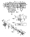
- eine in einem Längsschnitt dargestellte Rückfluss-Sperre mit einer Kartuschen-Aufnahme, in die eine Einsetzkartusche eingesetzt ist, die eine Strahldüse und ein, den von der Strahldüse über eine freie Strahlstrecke kommenden Stahl einfangendes:Einfangteil trägt,
- Fig. 2
- die Rückfluss-Sperre aus
Figur 1 in einer Seitenansicht, - Fig. 3
- die Rückfluss-Sperre aus
Figur 1 und 2 in einer Draufsicht, - Fig. 4
- die Rückfluss-Sperre aus den
Figuren 1 bis 3 in einer auseinandergezogenen Darstellung ihrer wesentlichen Bestandteile, - Fig. 5
- eine mit
Figur 1 bis 4 vergleichbar ausgestaltete und hier ebenfalls in einem Längsschnitt dargestellte Rückfluss-Sperre, bei der die an der Einsetzkartusche vorgesehene Strahldüse und Einfangteil als separate Bauteile ausgebildet sind, - Fig. 6
- die Rückfluss-Sperre aus
Figur 5 - Fig. 7
- die Rückfluss-Sperre aus
Figur 5 und 6 - Fig. 8
- die Rückfluss-Sperre aus den
Figuren 5 und 7 - Fig. 9
- eine Rückfluss-Sperre in einem Längsschnitt, bei der die Einsetzkartusche durch ein rohrförmiges Verbindungsstück ausgetauscht ist, wobei die hier dargestellte Rückfluss-Sperre einen Rückfluss allenfalls über einen integrierten Rückflußverhinderer verhindern kann,
- Fig. 10
- die Rückfluss-
Sperre aus Figur 9 in einer Seitenansicht, - Fig. 11
- die Rückfluss-Sperre
aus den Figuren 9 und 10 in einer auseinandergezogenen Darstellung ihrer wesentlichen Bestandteile, - Fig. 12
- eine Strahldüse für eine Rückfluss-Sperre gemäß den
Figuren 1 in einer perspektivischen Darstellung ihrer wesentlichen Bestandteile,bis 8 - Fig. 13
- die
Strahldüse aus Figur 12 in einem Längsschnitt, wobei die Strahldüse in einer hülsenförmigen Strahldüsen-Aufnahme derart verschieblich geführt ist, dass diese Strahldüse mit ihrer vorstehenden Düsenöffnung in Spritzstellung die Durchstecköffnung einer Membran durchstoßen kann, wobei die Strahldüse hier in ihrer in die hülsenförmige Strahldüsen-Aufnahme zurückgezogenen Bereitschaftsstellung gezeigt ist, - Fig. 14
- die in der Bereitschaftsstellung befindliche Strahldüse in einer Draufsicht auf die von der Strahldüse zu durchstoßende Membran,
- Fig. 15
- die Strahldüse
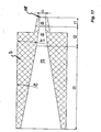
aus den Figuren 12 in der hier längsgeschnitten dargestellten Spritzposition der Düsenöffnung,bis 14 - Fig. 16
- die
Strahldüse aus Figur 12 in einer Stirnansicht auf die über die Durchstecköffnung der Membran vorstehende Strahlöffnung,bis 15 - Fig. 17
- die Rückfluss-Sperre in einem schematischen Längsschnitt im Bereich ihres Einfangteiles,
- Fig. 18
- eine gemäß den
Figuren 1 ausgestaltete Rückfluss-Sperre, die hier dem wannenbodenseitigen Wassereinlauf einer Badewanne zuströmseitig vorgeschaltet ist,bis 17 - Fig. 19
- eine Rückfluss-Sperre, die in den Wasserzulauf einer gegebenenfalls auch nachträglich an einem WC-Sitz oder eine WC-Keramik montierbaren Unterdusche zwischengeschaltet ist,
- Fig. 20
- die schematisch dargestellte Wasserführung der in
Figur 19 - Fig. 21
- eine weitere Ausführungsform einer Rückfluss-Sperre in einem Längsschnitt, wobei die in
Figur 21Figuren 1 gezeigten Rückfluss-Sperre ausgebildet ist,bis 18 - Fig. 22
- die Rückfluss-
Sperre aus Figur 21 in einer perspektivischen Einzelteildarstellung, - Fig. 23
- die Rückfluss-Sperre
aus den Figuren 21 und 22 in einer Draufsicht auf den Auslauf dieser Rückfluss-Sperre, - Fig. 24
- die in
den Figuren 21 und 23 gezeigte Rückfluss-Sperre in einer Seitenansicht, - Fig. 25
- die Rückfluss-Sperre
aus den Figuren 21 in einer Draufsicht auf die dem Auslauf abgewandte Oberseite,bis 24 - Fig. 26
- die hier ebenfalls längs geschnittene Rückfluss-Sperre
aus den Figuren 21 , wobei in dieser Rückfluss-Sperre eine gegen eine Rückstellkraft verschieblich geführte Strahldüse vorgesehen ist, die hier in zwei Schiebepositionen gezeigt ist,bis 25 - Fig. 27
- die Rückfluss-Sperre
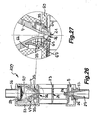
aus den Figuren 21 in den einander gegenübergestellten Schiebepositionen ihrer verschieblich geführten Strahldüse,bis 26 - Fig. 28
- die Strahldüse der in
den Figuren 21 gezeigten Rückfluss-Sperre in einem Längsschnitt,bis 27 - Fig. 29
- die Spritzdüse der in
den Figuren 21 gezeigten Rückfluss-Sperre im Bereich ihrer Düsenöffnung, undbis 27 - Fig. 30
- die Strahldüse
aus den Figuren 28 und 29 in einer Draufsicht auf die Düsenöffnung.
- Fig. 1
- a longitudinally-sectioned backflow barrier with a cartridge receptacle into which is inserted an insertion cartridge carrying a jet nozzle and a catching part which traps the steel coming from the jet nozzle via a free jet path;
- Fig. 2
- the reflux lock off
FIG. 1 in a side view, - Fig. 3
- the reflux lock off
FIGS. 1 and 2 in a plan view, - Fig. 4
- the reflux barrier from the
FIGS. 1 to 3 in an exploded view of their essential ingredients - Fig. 5
- one with
Figure 1 to 4 similarly designed and here also shown in a longitudinal section return flow barrier, in which the provided on the cartridge cartridge and Einfangteil are formed as separate components, - Fig. 6
- the reflux lock off
FIG. 5 in a side view, - Fig. 7
- the reflux lock off
FIGS. 5 and 6 in a plan view, - Fig. 8
- the reflux barrier from the
FIGS. 5 and 7 in an exploded view of its essential components, - Fig. 9
- a reflux barrier in a longitudinal section, in which the insertion cartridge is replaced by a tubular connecting piece, wherein the backflow barrier shown here can prevent a reflux at best via an integrated backflow preventer,
- Fig. 10
- the reflux lock off
FIG. 9 in a side view, - Fig. 11
- the reflux barrier from the
FIGS. 9 and 10 in an exploded view of its essential components, - Fig. 12
- a jet nozzle for a backflow barrier according to the
FIGS. 1 to 8 in a perspective view their essential components, - Fig. 13
- the jet nozzle off
FIG. 12 in a longitudinal section, wherein the jet nozzle is guided displaceably in a sleeve-shaped jet nozzle recording that this jet nozzle can pierce the insertion opening of a membrane with its projecting nozzle opening in injection position, wherein the jet nozzle is shown here in its retracted into the sleeve-shaped jet nozzle recording standby position . - Fig. 14
- the jet nozzle in the ready position in a plan view of the membrane to be pierced by the jet nozzle,
- Fig. 15
- the jet nozzle from the
FIGS. 12 to 14 in the injection position of the nozzle opening shown here cut longitudinally, - Fig. 16
- the jet nozzle off
FIGS. 12 to 15 in an end view onto the jet opening projecting beyond the push-through opening of the membrane, - Fig. 17
- the reflux barrier in a schematic longitudinal section in the region of its catching part,
- Fig. 18
- one according to the
FIGS. 1 to 17 configured reflux barrier, which is connected upstream of the tub bottom side water inlet of a bathtub on the inflow side, - Fig. 19
- a backflow-lock, which in the water supply one possibly also afterwards at a toilet-seat or a WC ceramic mountable under shower is interposed,
- Fig. 20
- the schematically illustrated water supply of in
FIG. 19 shown sub-shower, which has a "Shattaf-Shower" designated hand shower, the intermediate backflow barrier is recognizable in the water inlet, - Fig. 21
- a further embodiment of a reflux barrier in a longitudinal section, wherein the in
FIG. 21 shown reflux barrier similar to that in theFIGS. 1 to 18 formed reflux barrier is formed, - Fig. 22
- the reflux lock off
FIG. 21 in a perspective detail view, - Fig. 23
- the reflux barrier from the
FIGS. 21 and 22 in a plan view of the outlet of this reflux barrier, - Fig. 24
- in the
FIGS. 21 and 23 shown reflux barrier in a side view, - Fig. 25
- the reflux barrier from the
FIGS. 21 to 24 in a plan view of the outlet facing away from the top, - Fig. 26
- the here also longitudinally cut backflow barrier from the
FIGS. 21 to 25 , wherein in this reflux barrier, a jet nozzle, which is displaceably guided against a restoring force, is provided, which is shown here in two sliding positions, - Fig. 27
- the reflux barrier from the
FIGS. 21 to 26 in the opposing sliding positions of their slidably guided jet nozzle, - Fig. 28
- the jet nozzle in the
FIGS. 21 to 27 shown reflux barrier in a longitudinal section, - Fig. 29
- the spray nozzle in the
FIGS. 21 to 27 shown backflow barrier in the region of its nozzle opening, and - Fig. 30
- the jet nozzle from the
FIGS. 28 and 29 in a plan view of the nozzle opening.
In den
Die in den
Den in den
Die Einsetzöffnung 10, durch die die Einsetzkartusche 9 in das Innere der Kartuschen-Aufnahme 2 einsetzbar ist, ist mittels einer Kappe 12 verschließbar, an der die Einsetzkartusche 9 lösbar fixierbar ist. Die Kappe 12 ist hier mittels einer Steck-/Drehverbindung lösbar an der Kartuschen-Aufnahme 2 gehalten, wobei die Steck-/Drehverbindung beispielsweise als Bajonett- oder dergleichen Renkverbindung ausgebildet sein kann.The insertion opening 10, through which the
Die Kappe 12 hat einen Kappenfortsatz 13, auf den die Einsetzkartusche 9 mit ihrem benachbarten, stirnseitig offenen Kartuschen-Endbereich 14 aufschiebbar oder aufsteckbar ist.The
Die Einsetzkartusche 9 ist somit auch unter beengten Platzverhältnissen über die von außen stets erreichbare Kappe 12 leicht handhabbar.The
Die Einsetzkartusche 9 hat zumindest einen Einlass 15, der über einen zwischen dem Innenumfang der Kartuschen-Aufnahme 2 und dem Kartuschenaußenumfang umgrenzten und in Längsrichtung der Kartuschen-Aufnahme 2 beidseits umlaufend abgedichteten Ringraum 16 mit dem Zulauf 3 der Kartuschen-Aufnahme 2 verbindbar ist. Die Einsetzkartusche 9 hat hier zwei ovale und in Kartuschen-Umfangsrichtung orientierte Einlässe 15. Der Zulauf 3 der Kartuschen-Aufnahme 2 mündet in Umfangsrichtung gleichmäßig beabstandet von den hier auf gegenüberliegenden Seiten in gleicher Höhe angeordneten Einlässen 15 im Ringraum 16.The
Aus einem Vergleich der
Zwischen den Einlässen 15 und der Strahldüse 4 ist eine Einsetzpatrone 19 vorgesehen, die von dem stirnseitig offenen Kartuschen-Endbereich 14 in den Kartuschen-Innenraum einsetzbar ist. Die Einsetzpatrone 19 weist zumindest einen Rückflussverhinderer auf, der einen Wasserstrom nur in Richtung zur Strahldüse 4 zulässt. Die Einsetzpatrone 19 weist auch einen Durchflussmengenregler auf, der die pro Zeiteinheit durchströmende Wassermenge druckunabhängig auf einen bestimmten Wert zu begrenzen und einzuregeln hat.Between the
Bei den in
Bei der in den
Das Einsetzelement 52 ist im Gehäuse 53 derart lösbar fixierbar, dass die Einsetzöffnung 54 gleichzeitig den Auslauf 8 bildet. Die Strahldüsen-Aufnahme 50 ist an ihrer der Strahldüse 4 abgewandten Stirnseite mittels eines Deckels 55 verschließbar, der einen mit dem Zulauf verbindbaren Einlass trägt. Dieser Einlass ist hier als Anschlussnippel 56 ausgebildet, der über einen nicht weiter gezeigten Schlauch mit dem Zulauf verbindbar ist. Um stets einen ausreichenden Abstand zwischen der als Auslauf 8 dienenden Einsetzöffnung 54 und der jeweiligen Gehäuseunterlage zu gewährleisten, kann an das Gehäuse 53 zumindest ein Abstandhalter angeformt sein. Bevorzugt wird eine hier nicht gezeigte Ausführungsform, bei der mehrere Abstandhalter vorgesehen sind, die insbesondere in den Gehäuse-Eckbereichen angeordnet sind.The
In den
In den
In
Aus den
Die Strahldüse 4 der Rückfluss-Sperren 1, 100 hat die Druckenergie des aus dem Versorgungsnetz kommenden Wassers in die kinetische Energie des Wasserstrahls umzuformen. Dazu ist vorgesehen, dass sich die Strömungsführung trichterförmig in Richtung zur Düsenöffnung 21 der Strahldüse 4 verjüngt. Im Bereich der Düsenöffnung 21 ist die Strahldüse 4 als nippel- oder noppenförmiger Vorsprung 22 ausgebildet, um die durch die Adhäsionskräfte bewirkten Einflüsse auf den Wasserstrahl zu minimieren.The
In die freie Strahlstrecke 6 ist mit Abstand von Einfangteil 5 und Strahldüse 4 zumindest eine Spritz- oder Trennwand 23 angeordnet, die eine Durchstrahlöffnung 24 hat, die einen im Vergleich zum Strahlquerschnitt des Flüssigkeitsstrahles größeren lichten Querschnitt aufweist. Dabei ist der lichte Öffnungsquerschnitt der Durchstrahlöffnung 24 so bemessen, dass der Flüssigkeitsstrahl ungebündelt von der Durchstrahlöffnung 24 und gerade noch berührungslos durch diese hindurchtritt. Um den Flüssigkeitsstrahl nicht zu beeinträchtigen, ist die mit Abstand zwischen Strahldüse 4 und Einfangteil 5 vorgesehene Spritz- oder Trennwand 23 näher zum Einfangteil 5 angeordnet. Dabei wird eine Ausführungsform bevorzugt, bei der die Spritz- oder Trennwand 23 mindestens vier Millimeter vom Einfangteil 5 beabstandet ist.In the
Das Einfangteil 5 soll die kinetische Energie des von der Strahldüse 4 kommenden und vom Einfangteil 5 eingefangenen Wasserstrahls in eine entsprechende Druckenergie umwandeln, die anschließend für den beispielsweise aus der Spritzdüse, der Handbrause 45 einer Unterdusche oder einer anderen sanitären Verbrauchsstelle austretenden Reinigungs- oder Wasserstrahl benötigt wird. Aus den
Bei der Rückfluss-Sperre 1 mündet das Einfangteil 5 in einen am stirnseitigen Kartuschen-Ende 29 angeordneten KartuschenAblauf 30, der benachbart zum Ablauf 7 der Kartuschen-Aufnahme 2 vorgesehen ist. Die Einsetzkartusche 9 ist auch im Bereich ihres den Kartuschenablauf 30 aufweisenden Kartuschen-Endes 29 gegenüber dem Umfang der Kartuschen-Aufnahme 2 umlaufend abgedichtet.In the return flow barrier 1, the catching
Die Einsetzkartusche 9 der Rückfluss-Sperre 1 ist in der Kartuschen-Aufnahme 2 derart einsetzbar und fixierbar, dass die Strahldüse 4 mit dem Zulauf 3 der Kartuschen-Aufnahme 2 und gleichzeitig das Einfangteil 5 mit dem Ablauf 7 der Kartuschen-Aufnahme 2 verbunden ist. Die Einsetzkartusche 9 der Rückfluss-Sperre 1 weist in ihrem zwischen Strahldüse 4 und Einfangteil 5 angeordneten und die freie Strahlstrecke 6 begrenzenden Kartuschenabschnitt zumindest eine Kartuschenöffnung 11 auf, die mit dem Auslauf 8 der Kartuschen-Aufnahme 2 in Verbindung steht. Durch Lösen der Einsetzkartusche 9 aus der Kartuschen-Aufnahme 2 und Austausch dieser Einsetzkartusche 9 lässt sich die Rückfluss-Sperre 1, deren Kartuschen-Aufnahme 2 beispielsweise in einen WC-Sitz, eine WC-Keramik oder eine Badewanne eingeformt oder - wie hier - als ein in eine entsprechende Aufnahme am WC-Sitz, an der WC-Keramik oder an der Wannenöffnung einer Badewanne einsetzbares Gehäuse ausgebildet sein kann, mit geringem Aufwand an die verschiedensten vorgegebenen Bedingungen derart anpassen, dass stets eine optimale Funktion gewährleistet ist. Durch Lösen der Einsetzkartusche 9 aus der Kartuschen-Aufnahme 2 ist die Rückfluss-Sperre 1 auch leicht zu reinigen und bei Bedarf zu entkalken.The
Die in den
Da bei den übrigen Rückfluss-Sperren 1, 100 der die freie Strahlstrecke 6 der Einsetzkartusche 9 beziehungsweise des Einsetzelementes 52 bildende Abschnitt lediglich durch die zwei in Längsrichtung orientierte Verbindungsstege 51 gebildet wird, ist die Einsetzkartusche 9 der Rückfluss-Sperre 1 beziehungsweise das Einsetzelement 52 der Rückfluss-Sperre 100 im Bereich dieser freien Strahlstrecke 6 offen ausgebildet. Damit die Rückfluss-Sperren 1, 100 nach jedem Gebrauch rasch wieder trocknen können, ist im Bereich der freien Strahlstrecke 6 zumindest eine Belüftungsöffnung vorgesehen.Since in the
Bei der Rückfluss-Sperre 1 sind auf den dem Auslauf 8 der Kartuschen-Aufnahme 2 abgewandten Seite der in
Die hier gezeigten Rückfluss-Sperren 1, 100 bieten eine größtmögliche Sicherheit, um ein Rückfließen kontaminierten Wassers in einen mit dem Trinkwasser-Versorgungsnetz verbundenen Bereich auszuschließen. Um die Rückfluss-Sperre 1, 100 auch dort einsetzen zu können, wo eine derart hohe Sicherheit nicht gefordert wird, ist es möglich, die Einsetzkartusche 9 der Rückfluss-Sperre 1 in der Kartuschen-Aufnahme 2 gegen ein hülsenförmiges Verbindungsstück 31 auszutauschen, das die freie Strahlstrecke überbrückt und den Zulauf 3 der Kartuschen-Aufnahme 2 mit dem Ablauf 7 der Kartuschen-Aufnahme 2 gegebenenfalls unter Zwischenschaltung einer Einsetzpatrone 19, die zumindest einen Rückfluss-Verhinderer aufweist, verbindet.The
Aus den
Bauweise der Rückfluss-Sperre 1 den Austausch der Einsetzkartusche 9 gegen ein entsprechendes Verbindungsstück 31 erleichtert. Aus einem Vergleich der
In den
In
In
Dieser bevorzugte Bereich in der Ausgestaltung des Einfangteiles 5 ist in der nachstehenden Tabelle nochmals wiedergegeben:
Die hier dargestellte Rückfluss-Sperre 1 kann einer Dusche und insbesondere der einem WC-Sitz zugeordneten Unterdusche zuströmseitig vorgeschaltet sein. Darüber hinaus ist es aber auch möglich, die Rückfluss-Sperre 1 dem Wassereinlauf einer Badewanne 38 zuströmseitig vorzuschalten. Aus der schematischen Darstellung in
Der Wassereinlauf in die Badewanne 38 wird über eine manuell betätigbare Auslaufarmatur 41 bedient, die einen Warmwasserzulauf 42 und einen Kaltwasserzulauf 43 in sich vereint. Nachdem das von der Auslaufarmatur 41 kommende Wasser die Rückfluss-Sperre 1 erreicht hat, kann das durchströmende Wasser einen zwischen Rückfluss-Sperre 1 und dem Badewanneneinlauf 39 zwischengeschalteten Rückflussverhinderer 44 passieren, bevor das Wasser im Badewanneneinlauf 39 bodenseitig in die Badewanne 38 strömt.The water inlet into the
In den schematisierten Darstellungen gemäß den
Wie bereits oben ausgeführt wurde, ist die Strahldüse 4 der in den
In den
- 11
-
Rückfluss-Sperre (gemäß den
Figuren 1 bis 20 )Reflux barrier (according to theFIGS. 1 to 20 ) - 22
- Kartuschen-AufnahmeCartridge accommodating
- 33
- Zulauf (der Kartuschen-Aufnahme 2)Inlet (of the cartridge holder 2)
- 44
- Strahldüsejet
- 55
- Einfangteilcapturing member
- 66
- Strahlstreckebeamline
- 77
- Ablauf (der Kartuschen-Aufnahme 2)Procedure (Cartridge Recording 2)
- 88th
- Auslaufoutlet
- 99
- EinsetzkartuscheEinsetzkartusche
- 1010
- Einsetzöffnung (der Kartuschen-Aufnahme 2)Insertion opening (the cartridge holder 2)
- 1111
- Kartuschenöffnungcartridge opening
- 1212
- Kappecap
- 1313
- KappenfortsatzCap extension
- 1414
- Kartuschen-EndbereichCartridge end portion
- 1515
- Kartuscheneinlasscartridges inlet
- 1616
- Ringraumannulus
- 1717
- StrömungsführungswändeFlow guide walls
- 1818
- DurchtrittsöffnungThrough opening
- 1919
- Einsetzpatroneinsertable
- 2020
- Siebscree
- 2121
- Düsenöffnungnozzle opening
- 2222
- Vorsprung (der Strahldüse 4)Projection (the jet nozzle 4)
- 2323
- Spritz- oder TrennwandSpray or dividing wall
- 2424
- Durchstrahlöffnung (in der Spritz- oder Trennwand)Radiation opening (in the spray or dividing wall)
- 2525
- (hohlzylindrischer) Teilabschnitt(hollow cylindrical) section
- 2626
- (konisch ausgebildeter) Teilabschnitt(conically formed) section
- 2727
- Teil- oder Übergangsabschnitt (mit geringerer Konizität)Part or transition section (with less conicity)
- 2828
- Einfangöffnungcapture opening
- 2929
- Kartuschen-EndeCartridge end
- 3030
- Kartuschenablaufcartridge expiration
- 3131
- (hülsenförmiges) Verbindungsstück(sleeve-shaped) connector
- 3232
- Einlauföffnungeninlet openings
- 3333
- Ringabsatzannular shoulder
- 3434
- RückstellfederReturn spring
- 3535
- Membranmembrane
- 3636
- DurchstecköffnungThrough opening
- 3737
- Belüftungsöffnungventilation opening
- 3838
- Badewannebathtub
- 3939
- Badewanneneinlaufbath inlet
- 4040
- Badewannenauslauftub spout
- 4141
- Auslaufarmaturoutlet fitting
- 4242
- WarmwasserzulaufHot water supply
- 4343
- KaltwasserzulaufCold water supply
- 4444
- RückflussverhindererBackflow preventer
- 4545
- HandbrauseHandheld shower
- 4747
- Ringabsatzannular shoulder
- 4848
- Absperrelementshut-off
- 4949
- Wasserzufuhrwater supply
- 5050
- Strahldüsen-AufnahmeJets shooting
- 5151
- Verbindungsstegconnecting web
- 5252
- Einsetzelementinserter
- 5353
- Gehäusecasing
- 5454
- Einsetzöffnunginsertion
- 5555
- Deckelcover
- 5656
- Anschlussnippel (als Einlass)Connection nipple (as inlet)
- 5757
- Anschlussnippel (als Auslass)Connection nipple (as outlet)
- 5858
- Nutgroove
- 5959
- Wandungsöffnungwall opening
- 6060
- Führungswandguide wall
- 6161
- Halterungbracket
- 6262
- Gabel (der Halterung 61)Fork (the holder 61)
- 6363
- Belüftungsöffnung (der Rückfluss-Sperre 100)Ventilation opening (the reflux barrier 100)
- 6464
- Öffnung (in der Führungswand 60)Opening (in the guide wall 60)
- 6565
- DurchflussöffnungFlow opening
- 6666
- Innenraum (der Strahldüsen-Aufnahme 50)Interior (the jet nozzle receptacle 50)
- 6767
- Innenraum (der topfförmigen Membran 35)Interior (the cup-shaped membrane 35)
- 6868
- Abstandhalterspacer
- 6969
- Durchströmöffnungflow-through
- 7070
- Halteöffnungholding opening
- 7171
- Rücksprungreturn
- 100100
-
Rückfluss-Sperre (gemäß den
Figuren 21 bis 27 )Reflux barrier (according to theFIGS. 21 to 27 )
Claims (13)
Applications Claiming Priority (2)
| Application Number | Priority Date | Filing Date | Title |
|---|---|---|---|
| DE202012002585U DE202012002585U1 (en) | 2012-03-13 | 2012-03-13 | Backflow barrier for a shower |
| EP13713350.0A EP2825707B1 (en) | 2012-03-13 | 2013-03-05 | Check valve for an upwardly directed douche |
Related Parent Applications (2)
| Application Number | Title | Priority Date | Filing Date |
|---|---|---|---|
| EP13713350.0A Division EP2825707B1 (en) | 2012-03-13 | 2013-03-05 | Check valve for an upwardly directed douche |
| EP13713350.0A Division-Into EP2825707B1 (en) | 2012-03-13 | 2013-03-05 | Check valve for an upwardly directed douche |
Publications (2)
| Publication Number | Publication Date |
|---|---|
| EP2918741A1 true EP2918741A1 (en) | 2015-09-16 |
| EP2918741B1 EP2918741B1 (en) | 2017-08-09 |
Family
ID=48044714
Family Applications (4)
| Application Number | Title | Priority Date | Filing Date |
|---|---|---|---|
| EP18154708.4A Active EP3358094B1 (en) | 2012-03-13 | 2013-03-05 | Check valve |
| EP15002208.5A Active EP2980327B1 (en) | 2012-03-13 | 2013-03-05 | Vacuum breaker for a bidet |
| EP15000357.2A Active EP2918741B1 (en) | 2012-03-13 | 2013-03-05 | Return flow block |
| EP13713350.0A Active EP2825707B1 (en) | 2012-03-13 | 2013-03-05 | Check valve for an upwardly directed douche |
Family Applications Before (2)
| Application Number | Title | Priority Date | Filing Date |
|---|---|---|---|
| EP18154708.4A Active EP3358094B1 (en) | 2012-03-13 | 2013-03-05 | Check valve |
| EP15002208.5A Active EP2980327B1 (en) | 2012-03-13 | 2013-03-05 | Vacuum breaker for a bidet |
Family Applications After (1)
| Application Number | Title | Priority Date | Filing Date |
|---|---|---|---|
| EP13713350.0A Active EP2825707B1 (en) | 2012-03-13 | 2013-03-05 | Check valve for an upwardly directed douche |
Country Status (7)
| Country | Link |
|---|---|
| US (1) | US9909294B2 (en) |
| EP (4) | EP3358094B1 (en) |
| BR (1) | BR112014022363B1 (en) |
| DE (2) | DE202012002585U1 (en) |
| ES (4) | ES2640632T3 (en) |
| TR (2) | TR201802812T4 (en) |
| WO (1) | WO2013135350A1 (en) |
Families Citing this family (11)
| Publication number | Priority date | Publication date | Assignee | Title |
|---|---|---|---|---|
| JP6596943B2 (en) * | 2015-06-05 | 2019-10-30 | Toto株式会社 | Sanitary washing device |
| CN107165238A (en) * | 2016-03-08 | 2017-09-15 | 慈溪三和智能卫浴有限公司 | A kind of warm-water toilet seat water tank Manual water drain valve and warm-water toilet seat device |
| DE102017102115A1 (en) | 2017-02-03 | 2018-08-09 | Ulrich Stark-Gariglio | Toilet |
| DE202017102237U1 (en) | 2017-04-13 | 2018-07-16 | Neoperl Gmbh | Toilet cistern and corresponding use of an injector |
| DE102017108028A1 (en) * | 2017-04-13 | 2018-10-18 | Neoperl Gmbh | Toilet cistern and corresponding use of an injector |
| EP3712338A4 (en) * | 2017-11-15 | 2020-12-30 | Panasonic Intellectual Property Management Co., Ltd. | Flush toilet |
| EP3768903A4 (en) * | 2018-03-21 | 2022-05-04 | Eczacibasi Yapi Gerecleri Sanayi Ve Ticaret Anonim Sirketi | Bidet mechanism mounting system |
| US20210315751A1 (en) * | 2020-04-13 | 2021-10-14 | Neville Cameron | Commode wheelchair |
| TR202019956A2 (en) * | 2020-12-07 | 2021-04-21 | Iz Yapi Malzeme Ve Ekipmanlari Sanayi Ve Ticaret Anonim Sirketi | A backflow mechanism developed for use in toilet bowls. |
| DE102022102232A1 (en) | 2022-01-31 | 2023-08-03 | Grohe Ag | Functional unit for a shower toilet and shower toilet with a functional unit |
| DE202022103854U1 (en) | 2022-07-08 | 2023-10-18 | Neoperl Ag | Toilet seat ring |
Citations (4)
| Publication number | Priority date | Publication date | Assignee | Title |
|---|---|---|---|---|
| CH444076A (en) | 1965-04-14 | 1967-09-15 | Susten Anstalt | Device for preventing liquid from being sucked back from a container fed under pressure by a feed network into the feed network |
| DE2417731A1 (en) * | 1974-04-11 | 1975-10-30 | Aweco App & Geraetebau Kg | Water softener water return flow preventing valve - pushed into tight fit under water pressure and displaced by pneumatic pressure |
| DE2818691A1 (en) * | 1978-04-28 | 1979-10-31 | Walter Holzer | Domestic water using appliance return suction check - has nozzle in hydraulic piston moved toward opening against spring action |
| DE3708169A1 (en) * | 1987-03-13 | 1988-09-22 | Licentia Gmbh | Backflow preventer |
Family Cites Families (13)
| Publication number | Priority date | Publication date | Assignee | Title |
|---|---|---|---|---|
| US2071044A (en) | 1934-03-03 | 1937-02-16 | Western Electric Co | Method and apparatus for motion picture visual accompaniments to musical scores |
| US2071004A (en) * | 1936-03-23 | 1937-02-16 | William C Shanley | Vacuum breaker for flush valve devices |
| GB1166040A (en) * | 1965-12-22 | 1969-10-01 | Zanussi A Spa Industrie | Liquid Pollution Preventing Devices |
| DE1784274A1 (en) * | 1968-07-24 | 1972-06-08 | Licentia Gmbh | Back suction protection device, especially for washing machines and dishwashers |
| DE2417732C2 (en) * | 1974-04-11 | 1977-02-24 | Aweco App & Geraetebau Kg | Device for preventing the backflow of liquid from a water consumption device into the water supply system |
| US4592382A (en) * | 1984-08-27 | 1986-06-03 | Aqua-Giene, Inc. | Anti-siphon nozzle |
| DE9218982U1 (en) * | 1991-07-18 | 1996-10-17 | Hydro Systems Co | Chemical ejector with integrated elongated air gap |
| DE9113239U1 (en) * | 1991-10-24 | 1992-01-16 | Metallwerke Gebr. Seppelfricke Gmbh & Co, 4650 Gelsenkirchen, De | |
| US5518020A (en) * | 1994-06-14 | 1996-05-21 | Dema Engineering Co. | Proportioner |
| US5678592A (en) * | 1996-01-16 | 1997-10-21 | S. C. Johnson & Son, Inc. | Back flow prevention device |
| PL359448A1 (en) | 2002-04-03 | 2003-10-06 | Hans Sasserath & Co Kg | Set of isolating valves for water supply system |
| DE10308838A1 (en) * | 2003-02-27 | 2004-09-09 | Hans Sasserath & Co. Kg | Valve arrangement for a pipe separator |
| CA2767337C (en) * | 2008-07-21 | 2014-04-08 | Jules Allard | Retractable bidet |
-
2012
- 2012-03-13 DE DE202012002585U patent/DE202012002585U1/en not_active Expired - Lifetime
-
2013
- 2013-03-05 TR TR2018/02812T patent/TR201802812T4/en unknown
- 2013-03-05 US US14/385,045 patent/US9909294B2/en active Active
- 2013-03-05 EP EP18154708.4A patent/EP3358094B1/en active Active
- 2013-03-05 WO PCT/EP2013/000630 patent/WO2013135350A1/en active Application Filing
- 2013-03-05 EP EP15002208.5A patent/EP2980327B1/en active Active
- 2013-03-05 TR TR2018/15302T patent/TR201815302T4/en unknown
- 2013-03-05 ES ES15000357.2T patent/ES2640632T3/en active Active
- 2013-03-05 ES ES13713350.0T patent/ES2691964T3/en active Active
- 2013-03-05 EP EP15000357.2A patent/EP2918741B1/en active Active
- 2013-03-05 EP EP13713350.0A patent/EP2825707B1/en active Active
- 2013-03-05 DE DE102013003629A patent/DE102013003629A1/en active Pending
- 2013-03-05 ES ES15002208.5T patent/ES2659074T3/en active Active
- 2013-03-05 BR BR112014022363-7A patent/BR112014022363B1/en active IP Right Grant
- 2013-03-05 ES ES18154708T patent/ES2786629T3/en active Active
Patent Citations (4)
| Publication number | Priority date | Publication date | Assignee | Title |
|---|---|---|---|---|
| CH444076A (en) | 1965-04-14 | 1967-09-15 | Susten Anstalt | Device for preventing liquid from being sucked back from a container fed under pressure by a feed network into the feed network |
| DE2417731A1 (en) * | 1974-04-11 | 1975-10-30 | Aweco App & Geraetebau Kg | Water softener water return flow preventing valve - pushed into tight fit under water pressure and displaced by pneumatic pressure |
| DE2818691A1 (en) * | 1978-04-28 | 1979-10-31 | Walter Holzer | Domestic water using appliance return suction check - has nozzle in hydraulic piston moved toward opening against spring action |
| DE3708169A1 (en) * | 1987-03-13 | 1988-09-22 | Licentia Gmbh | Backflow preventer |
Also Published As
| Publication number | Publication date |
|---|---|
| US20150033464A1 (en) | 2015-02-05 |
| US9909294B2 (en) | 2018-03-06 |
| EP2918741B1 (en) | 2017-08-09 |
| EP2980327A1 (en) | 2016-02-03 |
| DE202012002585U1 (en) | 2013-06-17 |
| ES2640632T3 (en) | 2017-11-03 |
| BR112014022363B1 (en) | 2021-01-19 |
| EP2825707B1 (en) | 2018-08-15 |
| EP2825707A1 (en) | 2015-01-21 |
| WO2013135350A8 (en) | 2014-12-04 |
| TR201815302T4 (en) | 2018-11-21 |
| TR201802812T4 (en) | 2018-03-21 |
| WO2013135350A1 (en) | 2013-09-19 |
| ES2786629T3 (en) | 2020-10-13 |
| EP2980327B1 (en) | 2018-01-03 |
| ES2659074T3 (en) | 2018-03-13 |
| DE102013003629A1 (en) | 2013-09-19 |
| ES2691964T3 (en) | 2018-11-29 |
| EP3358094A1 (en) | 2018-08-08 |
| EP3358094B1 (en) | 2020-01-29 |
Similar Documents
| Publication | Publication Date | Title |
|---|---|---|
| EP2980327B1 (en) | Vacuum breaker for a bidet | |
| EP2025820B1 (en) | Sanitary unit for mounting in a spout | |
| EP1789636B1 (en) | Sanitary outlet unit | |
| EP2089581B1 (en) | Jet regulator | |
| EP2986787B1 (en) | Toilet with personal shower integrated into flushing water distributor | |
| EP3447201B1 (en) | Sanitary fitting having a mechanism for insertion of elements | |
| EP2167237B1 (en) | Water outlet for a low-pressure sanitary outlet fitting | |
| DE202013002055U1 (en) | Backflow barrier for a shower | |
| EP3705650A1 (en) | Toilet attachment | |
| DE4039329C2 (en) | Shower head | |
| EP0818585B1 (en) | Flush mountable connecting device | |
| EP1020571A2 (en) | Sanitary article, in particular a shower head, with a switching device to influence a fluid flow | |
| EP0441151A1 (en) | Watertap with backflow preventer | |
| EP2708664B1 (en) | Drain fitting comprising a drain body having the shape of a carafe | |
| DE102016201342B4 (en) | Device and steam lance for frothing and / or heating milk | |
| EP1761732B1 (en) | Air vent | |
| EP1390586B1 (en) | Sanitary faucet unit | |
| WO2013131617A1 (en) | Shower attachment | |
| DE10258832A1 (en) | Valve, for a domestic steam cleaning appliance, has a valve spindle to give a choice of dry steam or a wet steam mixture | |
| EP3992377A1 (en) | Jet regulator insert with recontamination protection | |
| DE19515959A1 (en) | Combined inlet and overflow bathtub fitting | |
| DE8505923U1 (en) | INLET DEVICE ON THE DRAIN PIPE OF A DIALYSIS STATION | |
| DE4005060A1 (en) | Toilet flushing mechanism automatic resetting system - injects air to water supply valve, with injected air forming sufficient pressure under lid | |
| DE102014116325A1 (en) | Supply and overflow set with drinking water protection function for bathtubs | |
| CH194243A (en) | Built-in flush valve with pipe interrupter. |
Legal Events
| Date | Code | Title | Description |
|---|---|---|---|
| PUAI | Public reference made under article 153(3) epc to a published international application that has entered the european phase |
Free format text: ORIGINAL CODE: 0009012 |
|
| AC | Divisional application: reference to earlier application |
Ref document number: 2825707 Country of ref document: EP Kind code of ref document: P |
|
| AK | Designated contracting states |
Kind code of ref document: A1 Designated state(s): AL AT BE BG CH CY CZ DE DK EE ES FI FR GB GR HR HU IE IS IT LI LT LU LV MC MK MT NL NO PL PT RO RS SE SI SK SM TR |
|
| AX | Request for extension of the european patent |
Extension state: BA ME |
|
| 17P | Request for examination filed |
Effective date: 20160316 |
|
| RBV | Designated contracting states (corrected) |
Designated state(s): AL AT BE BG CH CY CZ DE DK EE ES FI FR GB GR HR HU IE IS IT LI LT LU LV MC MK MT NL NO PL PT RO RS SE SI SK SM TR |
|
| GRAP | Despatch of communication of intention to grant a patent |
Free format text: ORIGINAL CODE: EPIDOSNIGR1 |
|
| INTG | Intention to grant announced |
Effective date: 20170420 |
|
| GRAS | Grant fee paid |
Free format text: ORIGINAL CODE: EPIDOSNIGR3 |
|
| GRAA | (expected) grant |
Free format text: ORIGINAL CODE: 0009210 |
|
| AC | Divisional application: reference to earlier application |
Ref document number: 2825707 Country of ref document: EP Kind code of ref document: P |
|
| AK | Designated contracting states |
Kind code of ref document: B1 Designated state(s): AL AT BE BG CH CY CZ DE DK EE ES FI FR GB GR HR HU IE IS IT LI LT LU LV MC MK MT NL NO PL PT RO RS SE SI SK SM TR |
|
| REG | Reference to a national code |
Ref country code: GB Ref legal event code: FG4D Free format text: NOT ENGLISH |
|
| REG | Reference to a national code |
Ref country code: CH Ref legal event code: EP Ref country code: AT Ref legal event code: REF Ref document number: 917004 Country of ref document: AT Kind code of ref document: T Effective date: 20170815 |
|
| REG | Reference to a national code |
Ref country code: IE Ref legal event code: FG4D Free format text: LANGUAGE OF EP DOCUMENT: GERMAN |
|
| REG | Reference to a national code |
Ref country code: CH Ref legal event code: NV Representative=s name: GACHNANG AG PATENTANWAELTE, CH |
|
| REG | Reference to a national code |
Ref country code: DE Ref legal event code: R096 Ref document number: 502013008054 Country of ref document: DE |
|
| REG | Reference to a national code |
Ref country code: ES Ref legal event code: FG2A Ref document number: 2640632 Country of ref document: ES Kind code of ref document: T3 Effective date: 20171103 |
|
| REG | Reference to a national code |
Ref country code: NL Ref legal event code: MP Effective date: 20170809 |
|
| REG | Reference to a national code |
Ref country code: LT Ref legal event code: MG4D |
|
| PG25 | Lapsed in a contracting state [announced via postgrant information from national office to epo] |
Ref country code: LT Free format text: LAPSE BECAUSE OF FAILURE TO SUBMIT A TRANSLATION OF THE DESCRIPTION OR TO PAY THE FEE WITHIN THE PRESCRIBED TIME-LIMIT Effective date: 20170809 Ref country code: SE Free format text: LAPSE BECAUSE OF FAILURE TO SUBMIT A TRANSLATION OF THE DESCRIPTION OR TO PAY THE FEE WITHIN THE PRESCRIBED TIME-LIMIT Effective date: 20170809 Ref country code: NL Free format text: LAPSE BECAUSE OF FAILURE TO SUBMIT A TRANSLATION OF THE DESCRIPTION OR TO PAY THE FEE WITHIN THE PRESCRIBED TIME-LIMIT Effective date: 20170809 Ref country code: HR Free format text: LAPSE BECAUSE OF FAILURE TO SUBMIT A TRANSLATION OF THE DESCRIPTION OR TO PAY THE FEE WITHIN THE PRESCRIBED TIME-LIMIT Effective date: 20170809 Ref country code: NO Free format text: LAPSE BECAUSE OF FAILURE TO SUBMIT A TRANSLATION OF THE DESCRIPTION OR TO PAY THE FEE WITHIN THE PRESCRIBED TIME-LIMIT Effective date: 20171109 |
|
| PG25 | Lapsed in a contracting state [announced via postgrant information from national office to epo] |
Ref country code: LV Free format text: LAPSE BECAUSE OF FAILURE TO SUBMIT A TRANSLATION OF THE DESCRIPTION OR TO PAY THE FEE WITHIN THE PRESCRIBED TIME-LIMIT Effective date: 20170809 Ref country code: IS Free format text: LAPSE BECAUSE OF FAILURE TO SUBMIT A TRANSLATION OF THE DESCRIPTION OR TO PAY THE FEE WITHIN THE PRESCRIBED TIME-LIMIT Effective date: 20171209 Ref country code: RS Free format text: LAPSE BECAUSE OF FAILURE TO SUBMIT A TRANSLATION OF THE DESCRIPTION OR TO PAY THE FEE WITHIN THE PRESCRIBED TIME-LIMIT Effective date: 20170809 Ref country code: GR Free format text: LAPSE BECAUSE OF FAILURE TO SUBMIT A TRANSLATION OF THE DESCRIPTION OR TO PAY THE FEE WITHIN THE PRESCRIBED TIME-LIMIT Effective date: 20171110 Ref country code: BG Free format text: LAPSE BECAUSE OF FAILURE TO SUBMIT A TRANSLATION OF THE DESCRIPTION OR TO PAY THE FEE WITHIN THE PRESCRIBED TIME-LIMIT Effective date: 20171109 Ref country code: PL Free format text: LAPSE BECAUSE OF FAILURE TO SUBMIT A TRANSLATION OF THE DESCRIPTION OR TO PAY THE FEE WITHIN THE PRESCRIBED TIME-LIMIT Effective date: 20170809 |
|
| REG | Reference to a national code |
Ref country code: FR Ref legal event code: PLFP Year of fee payment: 6 |
|
| PG25 | Lapsed in a contracting state [announced via postgrant information from national office to epo] |
Ref country code: RO Free format text: LAPSE BECAUSE OF FAILURE TO SUBMIT A TRANSLATION OF THE DESCRIPTION OR TO PAY THE FEE WITHIN THE PRESCRIBED TIME-LIMIT Effective date: 20170809 Ref country code: DK Free format text: LAPSE BECAUSE OF FAILURE TO SUBMIT A TRANSLATION OF THE DESCRIPTION OR TO PAY THE FEE WITHIN THE PRESCRIBED TIME-LIMIT Effective date: 20170809 Ref country code: CZ Free format text: LAPSE BECAUSE OF FAILURE TO SUBMIT A TRANSLATION OF THE DESCRIPTION OR TO PAY THE FEE WITHIN THE PRESCRIBED TIME-LIMIT Effective date: 20170809 |
|
| REG | Reference to a national code |
Ref country code: DE Ref legal event code: R097 Ref document number: 502013008054 Country of ref document: DE |
|
| PG25 | Lapsed in a contracting state [announced via postgrant information from national office to epo] |
Ref country code: SK Free format text: LAPSE BECAUSE OF FAILURE TO SUBMIT A TRANSLATION OF THE DESCRIPTION OR TO PAY THE FEE WITHIN THE PRESCRIBED TIME-LIMIT Effective date: 20170809 Ref country code: EE Free format text: LAPSE BECAUSE OF FAILURE TO SUBMIT A TRANSLATION OF THE DESCRIPTION OR TO PAY THE FEE WITHIN THE PRESCRIBED TIME-LIMIT Effective date: 20170809 Ref country code: SM Free format text: LAPSE BECAUSE OF FAILURE TO SUBMIT A TRANSLATION OF THE DESCRIPTION OR TO PAY THE FEE WITHIN THE PRESCRIBED TIME-LIMIT Effective date: 20170809 |
|
| PLBE | No opposition filed within time limit |
Free format text: ORIGINAL CODE: 0009261 |
|
| STAA | Information on the status of an ep patent application or granted ep patent |
Free format text: STATUS: NO OPPOSITION FILED WITHIN TIME LIMIT |
|
| 26N | No opposition filed |
Effective date: 20180511 |
|
| PG25 | Lapsed in a contracting state [announced via postgrant information from national office to epo] |
Ref country code: SI Free format text: LAPSE BECAUSE OF FAILURE TO SUBMIT A TRANSLATION OF THE DESCRIPTION OR TO PAY THE FEE WITHIN THE PRESCRIBED TIME-LIMIT Effective date: 20170809 |
|
| PG25 | Lapsed in a contracting state [announced via postgrant information from national office to epo] |
Ref country code: MT Free format text: LAPSE BECAUSE OF FAILURE TO SUBMIT A TRANSLATION OF THE DESCRIPTION OR TO PAY THE FEE WITHIN THE PRESCRIBED TIME-LIMIT Effective date: 20170809 |
|
| PG25 | Lapsed in a contracting state [announced via postgrant information from national office to epo] |
Ref country code: MC Free format text: LAPSE BECAUSE OF FAILURE TO SUBMIT A TRANSLATION OF THE DESCRIPTION OR TO PAY THE FEE WITHIN THE PRESCRIBED TIME-LIMIT Effective date: 20170809 |
|
| REG | Reference to a national code |
Ref country code: BE Ref legal event code: MM Effective date: 20180331 |
|
| REG | Reference to a national code |
Ref country code: IE Ref legal event code: MM4A |
|
| PG25 | Lapsed in a contracting state [announced via postgrant information from national office to epo] |
Ref country code: LU Free format text: LAPSE BECAUSE OF NON-PAYMENT OF DUE FEES Effective date: 20180305 |
|
| PG25 | Lapsed in a contracting state [announced via postgrant information from national office to epo] |
Ref country code: IE Free format text: LAPSE BECAUSE OF NON-PAYMENT OF DUE FEES Effective date: 20180305 |
|
| PG25 | Lapsed in a contracting state [announced via postgrant information from national office to epo] |
Ref country code: BE Free format text: LAPSE BECAUSE OF NON-PAYMENT OF DUE FEES Effective date: 20180331 |
|
| PG25 | Lapsed in a contracting state [announced via postgrant information from national office to epo] |
Ref country code: PT Free format text: LAPSE BECAUSE OF FAILURE TO SUBMIT A TRANSLATION OF THE DESCRIPTION OR TO PAY THE FEE WITHIN THE PRESCRIBED TIME-LIMIT Effective date: 20170809 |
|
| PG25 | Lapsed in a contracting state [announced via postgrant information from national office to epo] |
Ref country code: CY Free format text: LAPSE BECAUSE OF FAILURE TO SUBMIT A TRANSLATION OF THE DESCRIPTION OR TO PAY THE FEE WITHIN THE PRESCRIBED TIME-LIMIT Effective date: 20170809 Ref country code: HU Free format text: LAPSE BECAUSE OF FAILURE TO SUBMIT A TRANSLATION OF THE DESCRIPTION OR TO PAY THE FEE WITHIN THE PRESCRIBED TIME-LIMIT; INVALID AB INITIO Effective date: 20130305 Ref country code: MK Free format text: LAPSE BECAUSE OF NON-PAYMENT OF DUE FEES Effective date: 20170809 |
|
| PG25 | Lapsed in a contracting state [announced via postgrant information from national office to epo] |
Ref country code: AL Free format text: LAPSE BECAUSE OF FAILURE TO SUBMIT A TRANSLATION OF THE DESCRIPTION OR TO PAY THE FEE WITHIN THE PRESCRIBED TIME-LIMIT Effective date: 20170809 |
|
| PGFP | Annual fee paid to national office [announced via postgrant information from national office to epo] |
Ref country code: FR Payment date: 20230320 Year of fee payment: 11 Ref country code: FI Payment date: 20230320 Year of fee payment: 11 Ref country code: AT Payment date: 20230317 Year of fee payment: 11 |
|
| PGFP | Annual fee paid to national office [announced via postgrant information from national office to epo] |
Ref country code: TR Payment date: 20230303 Year of fee payment: 11 Ref country code: GB Payment date: 20230323 Year of fee payment: 11 |
|
| PGFP | Annual fee paid to national office [announced via postgrant information from national office to epo] |
Ref country code: IT Payment date: 20230331 Year of fee payment: 11 Ref country code: ES Payment date: 20230414 Year of fee payment: 11 Ref country code: DE Payment date: 20230420 Year of fee payment: 11 Ref country code: CH Payment date: 20230402 Year of fee payment: 11 |
|
| PGFP | Annual fee paid to national office [announced via postgrant information from national office to epo] |
Ref country code: AT Payment date: 20240318 Year of fee payment: 12 |
|
| PGFP | Annual fee paid to national office [announced via postgrant information from national office to epo] |
Ref country code: FI Payment date: 20240319 Year of fee payment: 12 Ref country code: GB Payment date: 20240322 Year of fee payment: 12 |