EP2918239A1 - Katheteranordnung mit niedrigem Profil und zugehörige Systeme und Verfahren - Google Patents
Katheteranordnung mit niedrigem Profil und zugehörige Systeme und Verfahren Download PDFInfo
- Publication number
- EP2918239A1 EP2918239A1 EP15158850.6A EP15158850A EP2918239A1 EP 2918239 A1 EP2918239 A1 EP 2918239A1 EP 15158850 A EP15158850 A EP 15158850A EP 2918239 A1 EP2918239 A1 EP 2918239A1
- Authority
- EP
- European Patent Office
- Prior art keywords
- strut
- electrodes
- shaft
- end portion
- leg
- Prior art date
- Legal status (The legal status is an assumption and is not a legal conclusion. Google has not performed a legal analysis and makes no representation as to the accuracy of the status listed.)
- Granted
Links
Images


Classifications
-
- A—HUMAN NECESSITIES
- A61—MEDICAL OR VETERINARY SCIENCE; HYGIENE
- A61B—DIAGNOSIS; SURGERY; IDENTIFICATION
- A61B18/00—Surgical instruments, devices or methods for transferring non-mechanical forms of energy to or from the body
- A61B18/04—Surgical instruments, devices or methods for transferring non-mechanical forms of energy to or from the body by heating
- A61B18/12—Surgical instruments, devices or methods for transferring non-mechanical forms of energy to or from the body by heating by passing a current through the tissue to be heated, e.g. high-frequency current
- A61B18/14—Probes or electrodes therefor
- A61B18/1492—Probes or electrodes therefor having a flexible, catheter-like structure, e.g. for heart ablation
-
- A—HUMAN NECESSITIES
- A61—MEDICAL OR VETERINARY SCIENCE; HYGIENE
- A61N—ELECTROTHERAPY; MAGNETOTHERAPY; RADIATION THERAPY; ULTRASOUND THERAPY
- A61N7/00—Ultrasound therapy
- A61N7/02—Localised ultrasound hyperthermia
-
- A—HUMAN NECESSITIES
- A61—MEDICAL OR VETERINARY SCIENCE; HYGIENE
- A61B—DIAGNOSIS; SURGERY; IDENTIFICATION
- A61B18/00—Surgical instruments, devices or methods for transferring non-mechanical forms of energy to or from the body
- A61B2018/00053—Mechanical features of the instrument of device
- A61B2018/0016—Energy applicators arranged in a two- or three dimensional array
-
- A—HUMAN NECESSITIES
- A61—MEDICAL OR VETERINARY SCIENCE; HYGIENE
- A61B—DIAGNOSIS; SURGERY; IDENTIFICATION
- A61B18/00—Surgical instruments, devices or methods for transferring non-mechanical forms of energy to or from the body
- A61B2018/00053—Mechanical features of the instrument of device
- A61B2018/00214—Expandable means emitting energy, e.g. by elements carried thereon
-
- A—HUMAN NECESSITIES
- A61—MEDICAL OR VETERINARY SCIENCE; HYGIENE
- A61B—DIAGNOSIS; SURGERY; IDENTIFICATION
- A61B18/00—Surgical instruments, devices or methods for transferring non-mechanical forms of energy to or from the body
- A61B2018/00053—Mechanical features of the instrument of device
- A61B2018/00214—Expandable means emitting energy, e.g. by elements carried thereon
- A61B2018/00267—Expandable means emitting energy, e.g. by elements carried thereon having a basket shaped structure
-
- A—HUMAN NECESSITIES
- A61—MEDICAL OR VETERINARY SCIENCE; HYGIENE
- A61B—DIAGNOSIS; SURGERY; IDENTIFICATION
- A61B18/00—Surgical instruments, devices or methods for transferring non-mechanical forms of energy to or from the body
- A61B2018/00315—Surgical instruments, devices or methods for transferring non-mechanical forms of energy to or from the body for treatment of particular body parts
- A61B2018/00345—Vascular system
- A61B2018/00404—Blood vessels other than those in or around the heart
-
- A—HUMAN NECESSITIES
- A61—MEDICAL OR VETERINARY SCIENCE; HYGIENE
- A61B—DIAGNOSIS; SURGERY; IDENTIFICATION
- A61B18/00—Surgical instruments, devices or methods for transferring non-mechanical forms of energy to or from the body
- A61B2018/00315—Surgical instruments, devices or methods for transferring non-mechanical forms of energy to or from the body for treatment of particular body parts
- A61B2018/00434—Neural system
-
- A—HUMAN NECESSITIES
- A61—MEDICAL OR VETERINARY SCIENCE; HYGIENE
- A61B—DIAGNOSIS; SURGERY; IDENTIFICATION
- A61B18/00—Surgical instruments, devices or methods for transferring non-mechanical forms of energy to or from the body
- A61B2018/00315—Surgical instruments, devices or methods for transferring non-mechanical forms of energy to or from the body for treatment of particular body parts
- A61B2018/00505—Urinary tract
- A61B2018/00511—Kidney
-
- A—HUMAN NECESSITIES
- A61—MEDICAL OR VETERINARY SCIENCE; HYGIENE
- A61B—DIAGNOSIS; SURGERY; IDENTIFICATION
- A61B18/00—Surgical instruments, devices or methods for transferring non-mechanical forms of energy to or from the body
- A61B2018/00571—Surgical instruments, devices or methods for transferring non-mechanical forms of energy to or from the body for achieving a particular surgical effect
- A61B2018/00577—Ablation
-
- A—HUMAN NECESSITIES
- A61—MEDICAL OR VETERINARY SCIENCE; HYGIENE
- A61B—DIAGNOSIS; SURGERY; IDENTIFICATION
- A61B18/00—Surgical instruments, devices or methods for transferring non-mechanical forms of energy to or from the body
- A61B2018/00636—Sensing and controlling the application of energy
- A61B2018/00642—Sensing and controlling the application of energy with feedback, i.e. closed loop control
-
- A—HUMAN NECESSITIES
- A61—MEDICAL OR VETERINARY SCIENCE; HYGIENE
- A61B—DIAGNOSIS; SURGERY; IDENTIFICATION
- A61B18/00—Surgical instruments, devices or methods for transferring non-mechanical forms of energy to or from the body
- A61B18/04—Surgical instruments, devices or methods for transferring non-mechanical forms of energy to or from the body by heating
- A61B18/12—Surgical instruments, devices or methods for transferring non-mechanical forms of energy to or from the body by heating by passing a current through the tissue to be heated, e.g. high-frequency current
- A61B18/14—Probes or electrodes therefor
- A61B2018/1405—Electrodes having a specific shape
- A61B2018/1407—Loop
-
- A—HUMAN NECESSITIES
- A61—MEDICAL OR VETERINARY SCIENCE; HYGIENE
- A61B—DIAGNOSIS; SURGERY; IDENTIFICATION
- A61B18/00—Surgical instruments, devices or methods for transferring non-mechanical forms of energy to or from the body
- A61B18/04—Surgical instruments, devices or methods for transferring non-mechanical forms of energy to or from the body by heating
- A61B18/12—Surgical instruments, devices or methods for transferring non-mechanical forms of energy to or from the body by heating by passing a current through the tissue to be heated, e.g. high-frequency current
- A61B18/14—Probes or electrodes therefor
- A61B2018/1467—Probes or electrodes therefor using more than two electrodes on a single probe
-
- A—HUMAN NECESSITIES
- A61—MEDICAL OR VETERINARY SCIENCE; HYGIENE
- A61M—DEVICES FOR INTRODUCING MEDIA INTO, OR ONTO, THE BODY; DEVICES FOR TRANSDUCING BODY MEDIA OR FOR TAKING MEDIA FROM THE BODY; DEVICES FOR PRODUCING OR ENDING SLEEP OR STUPOR
- A61M25/00—Catheters; Hollow probes
- A61M25/0067—Catheters; Hollow probes characterised by the distal end, e.g. tips
- A61M25/0082—Catheter tip comprising a tool
- A61M25/0084—Catheter tip comprising a tool being one or more injection needles
-
- A—HUMAN NECESSITIES
- A61—MEDICAL OR VETERINARY SCIENCE; HYGIENE
- A61N—ELECTROTHERAPY; MAGNETOTHERAPY; RADIATION THERAPY; ULTRASOUND THERAPY
- A61N1/00—Electrotherapy; Circuits therefor
- A61N1/18—Applying electric currents by contact electrodes
- A61N1/20—Applying electric currents by contact electrodes continuous direct currents
- A61N1/205—Applying electric currents by contact electrodes continuous direct currents for promoting a biological process
-
- A—HUMAN NECESSITIES
- A61—MEDICAL OR VETERINARY SCIENCE; HYGIENE
- A61N—ELECTROTHERAPY; MAGNETOTHERAPY; RADIATION THERAPY; ULTRASOUND THERAPY
- A61N7/00—Ultrasound therapy
- A61N2007/0004—Applications of ultrasound therapy
- A61N2007/0021—Neural system treatment
- A61N2007/0026—Stimulation of nerve tissue
-
- A—HUMAN NECESSITIES
- A61—MEDICAL OR VETERINARY SCIENCE; HYGIENE
- A61N—ELECTROTHERAPY; MAGNETOTHERAPY; RADIATION THERAPY; ULTRASOUND THERAPY
- A61N7/00—Ultrasound therapy
- A61N2007/0004—Applications of ultrasound therapy
- A61N2007/0021—Neural system treatment
- A61N2007/003—Destruction of nerve tissue
Definitions
- the present technology is related to catheters.
- at least some embodiments are related to low profile neuromodulation catheters including energy delivery elements configured to deliver energy to nerves at or near a treatment location within a body lumen.
- the sympathetic nervous system is a primarily involuntary bodily control system typically associated with stress responses. Fibers of the SNS extend through tissue in almost every organ system of the human body and can affect characteristics such as pupil diameter, gut motility, and urinary output. Such regulation can have adaptive utility in maintaining homeostasis or in preparing the body for rapid response to environmental factors. Chronic activation of the SNS, however, is a common maladaptive response that can drive the progression of many disease states. Excessive activation of the renal SNS, in particular, has been identified experimentally and in humans as a likely contributor to the complex pathophysiologies of hypertension, states of volume overload (e.g., heart failure), and progressive renal disease.
- states of volume overload e.g., heart failure
- Sympathetic nerves of the kidneys terminate in the renal blood vessels, the juxtaglomerular apparatus, and the renal tubules, among other structures. Stimulation of the renal sympathetic nerves can cause, for example, increased renin release, increased sodium reabsorption, and reduced renal blood flow. These and other neural-regulated components of renal function are considerably stimulated in disease states characterized by heightened sympathetic tone. For example, reduced renal blood flow and glomerular filtration rate as a result of renal sympathetic efferent stimulation is likely a cornerstone of the loss of renal function in cardio-renal syndrome (i.e., renal dysfunction as a progressive complication of chronic heart failure).
- Pharmacologic strategies to thwart the consequences of renal sympathetic stimulation include centrally-acting sympatholytic drugs, beta blockers (e.g., to reduce renin release), angiotensin-converting enzyme inhibitors and receptor blockers (e.g., to block the action of angiotensin II and aldosterone activation consequent to renin release), and diuretics (e.g., to counter renal sympathetic mediated sodium and water retention).
- beta blockers e.g., to reduce renin release
- angiotensin-converting enzyme inhibitors and receptor blockers e.g., to block the action of angiotensin II and aldosterone activation consequent to renin release
- diuretics e.g., to counter renal sympathetic mediated sodium and water retention.
- the present technology is related to catheters, such as low profile neuromodulation catheters with independent expansion members carrying energy delivery elements configured to deliver energy to nerves at or near a treatment location within a body lumen.
- Embodiments of the present technology are directed to catheters having energy delivery elements arranged in a staggered or misaligned arrangement when the catheter is in a low-profile delivery configuration. In this way, the energy delivery elements are not overlapping when the catheter is in a low-profile delivery configuration, which is expected to reduce the overall profile of the catheter.
- the treatment assembly is transformable to an expanded, deployed arrangement such that the energy delivery elements are aligned relative to each other (e.g., lie in a plane that is orthogonal relative to a longitudinal axis of the catheter) and are positioned to produce a desired ablation pattern in target tissue.
- Neuromodulation catheters configured in accordance with embodiments of the present technology can include, for example, an elongated tubular shaft extending along a longitudinal axis.
- the elongated shaft includes a proximal portion and a distal portion.
- the catheter can also include a treatment assembly at the distal portion of the shaft and configured to be located at a target location within a blood vessel of a human patient.
- the treatment assembly includes a pair of electrodes.
- the treatment assembly is transformable between (a) a low-profile delivery configuration wherein the pair of electrodes are in a staggered arrangement relative to each other along the longitudinal axis, and (b) an expanded deployed configuration wherein the pair of electrodes are aligned along an electrode axis that is orthogonal relative to the longitudinal axis.
- FIGS. 1-6C Specific details of several embodiments of the present technology are described herein with reference to FIGS. 1-6C . Although many of the embodiments are described herein with respect to devices and systems for percutaneous intravascular renal neuromodulation, other clinical applications and other embodiments in addition to those described herein are within the scope of the present technology. For example, at least some embodiments may be useful for neuromodulation within a body lumen other than a blood vessel, for non-renal neuromodulation, and/or for use in therapies other than neuromodulation. It should be noted that other embodiments in addition to those disclosed herein are within the scope of the present technology. Furthermore, embodiments of the present technology can have different configurations and components, and may be used for procedures different from those disclosed herein.
- embodiments of the present technology can have configurations, components, and/or procedures in addition to those disclosed herein and that these and other embodiments can be without several of the configurations, components, and/or procedures disclosed herein without deviating from the present technology.
- distal and proximal define a position or direction with respect to a clinician or a clinician's control device (e.g., a handle of a catheter).
- distal and distal refer to a position distant from or in a direction away from a clinician or a clinician's control device.
- proximal and proximally refer to a position near or in a direction toward a clinician or a clinician's control device.
- the headings provided herein are for convenience only and should not be construed as limiting the subject matter disclosed.
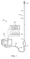
- FIG. 1 is a perspective view of a system 100 (e.g., a neuromodulation system) configured in accordance with an embodiment of the present technology.
- the system 100 can include a catheter 102 (e.g., a neuromodulation catheter), a console 104, and a cable 106 extending therebetween.
- the catheter 102 can include an elongate shaft 108 having a proximal end portion 110 and a distal end portion 112.
- the catheter 102 can further include a handle 114 and a treatment or therapeutic assembly 116 operably connected to the shaft 108 via, respectively, the proximal and distal end portions 110, 112 of the shaft 108.
- the shaft 108 can be configured to intravascularly locate the treatment assembly 116 at a treatment location within a body lumen, such as a suitable blood vessel, duct, airway, or other naturally occurring lumen within the human body.
- the treatment assembly 116 can be configured to provide or support therapy (e.g., a neuromodulation treatment) at the treatment location.
- the treatment assembly 116 may be configured to be radially constrained and slidably disposed within a delivery sheath (not shown) while the catheter 102 is being deployed within a body lumen.
- the outside diameter of the sheath can typically be 5, 6, or 7 French (1.66, 2, or 2.33 mm) or another suitable size.
- the catheter 102 can be steerable or non-steerable and configured for deployment without a guide wire.
- the catheter 102 can also be configured for deployment via a guide catheter (not shown) with or without the use of a delivery sheath or a guide wire.
- the console 104 can be configured to control, monitor, supply energy, and/or otherwise support operation of the catheter 102.
- the catheter 102 can be self-contained or otherwise configured for operation without connection to a console 104.
- the console 104 can be configured to generate a selected form and/or magnitude of energy for delivery to tissue at or near a treatment location via the treatment assembly 116.
- the console 104 can have different configurations depending on the treatment modality of the catheter 102.
- the console 104 can include an energy generator (not shown) configured to generate radio frequency (RF) energy (e.g., monopolar and/or bipolar RF energy), pulsed electrical energy, microwave energy, ultrasound energy (e.g., intravascularly delivered ultrasound energy, high-intensity focused ultrasound energy), direct heat, electromagnetic radiation (e.g., infrared, visible, and/or gamma radiation), and/or another suitable type of energy.
- RF radio frequency
- the console 104 can include a chemical reservoir (not shown) and can be configured to supply the catheter 102 with one or more chemicals.
- the system 100 includes a control device 118 along the cable 106.
- the control device 118 can be configured to initiate, terminate, and/or adjust operation of one or more components of the catheter 102 directly and/or via the console 104.
- the control device 118 can be absent or can have another suitable location, such as within the handle 114.
- the console 104 can be configured to execute an automated control algorithm 120 and/or to receive control instructions from an operator.
- the console 104 can be configured to provide information to an operator before, during, and/or after a treatment procedure via an evaluation/feedback algorithm 122.
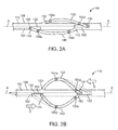
- FIGS.2A-2C are enlarged views of the treatment assembly 116. More specifically, in FIG. 2A , the treatment assembly 116 is shown in a low-profile delivery configuration. In FIGS. 2B and 2C , the treatment assembly 116 is shown in an expanded deployed configuration.
- the treatment assembly 116 can include a first strut or expansion member 130 and a second strut or expansion member 140.
- the first strut 130 is arranged about a longitudinal axis A of the shaft 108 along a first curved path
- the second strut 140 is arranged about the longitudinal axis A along a second curved path offset from the first curved path.
- the first and second struts 130 and 140 may be composed of metal (e.g., titanium nickel alloy commonly known as nitinol or spring tempered stainless steel). In other embodiments, the first and second struts 130 and 140 may be composed of other suitable materials. Further, in still other embodiments (such as those described below with reference to FIG. 3A-3C ), the treatment assembly 116 may include more than two struts or expansion members.
- the first and second struts 130 and 140 can be movably (e.g., slidably) connected to the shaft 108.
- the first strut 130 can include a first fixed end portion 132 coupled to the shaft 108 and a first free end portion 134 slidably engaged with the shaft 108 at a location distal of the first fixed end portion 132.
- the first free end portion 134 is slidably disposed within a first channel or groove 150 of the shaft 108. In other embodiments, however, the first free end portion 134 may be slidably engaged with the shaft 108 via another arrangement.
- the second strut 140 includes a second fixed end portion 142 coupled to the shaft 108 and a second free end portion 144 slidably engaged with the shaft 108 at a location proximal of the second fixed end portion 142.
- the second free end portion 144 is slidably disposed within a second channel or groove 152.
- the first fixed end portion 132 is adjacent to the second free end portion 144 along the shaft 108
- the first free end portion 134 is adjacent the second fixed end portion 142.
- the first and second fixed/free ends 132/134/142/144 may have a different arrangement relative to each other along the shaft 108.
- the first and second struts 130 and 140 are configured to expand radially outward from the shaft 108 in conjunction with the corresponding free end portions 134 and 144 slidably moving in opposite directions along the shaft 108.
- the treatment assembly 116 further comprises a plurality of energy delivery elements or electrodes 154 (identified individually as first through fourth electrodes 154a-154d, respectively, and referred to collectively as electrodes 154).
- electrodes 154 in the illustrated embodiment are shown as ring or band electrodes, it will be appreciated that the electrodes 154 may have various configurations/shapes (e.g., electrodes with generally flat/planar surfaces, electrodes with crescent-shaped cross-sectional profiles, etc.).
- the electrodes 154 are arranged in pairs, including a first pair (comprising the first and second electrodes 154a and 154b) and a second pair (comprising the third and fourth electrodes 154c and 154d).
- the electrodes 154 are in a staggered arrangement relative to each other along the longitudinal axis A.
- the pairs of electrodes (the first pair 154a/154b and the second pair 154c/154d) are aligned along electrode axes that are orthogonal relative to the longitudinal axis A.
- the treatment assembly 116 may have a different number of electrodes 154 and/or the electrodes 154 may have different arrangements/positions relative to each other on the treatment assembly 116.
- the treatment assembly 116 can include energy delivery elements other than electrodes, such as devices suitable for providing other energy-based or chemical-based treatment modalities.
- a first control member 160 (shown schematically as a broken line) is operably coupled between the first free end portion 134 of the first strut 130 and the handle 114 ( FIG. 1 ) at the proximal end portion 110 ( FIG. 1 ) of the shaft 108.
- a second control member 162 (also shown schematically as a broken line) is operably coupled between the second free end portion 144 of the second strut 140 and the handle 114 ( FIG. 1 ).
- the first control member 160 comprises a pull wire and the second control member 162 comprises a push wire.
- the first control member 160 and/or second control member 162 may have a different configuration.
- the first and second control members 160 and 162 may be manually actuated by one or more operators (not shown) such as levers or knobs to transform the treatment assembly 116 between the delivery configuration (as shown in FIG. 2A ) and the deployed configuration.
- FIGS. 2B and 2C are an enlarged side view and an enlarged perspective view, respectively, of the treatment assembly 116 in the deployed configuration.
- first control member 160 radially expands the first strut 130.
- second control member 162 radially expands the second strut 140.
- the first control member 160 comprises a pull wire adapted to be pushed/pulled by the operator (not shown) to slidably move the first free end portion 134 along slot 150 while the first fixed end portion 132 remains stationary
- the second control member 162 comprises a push wire adapted to be pulled/pushed by the operator to slidably move the second free end portion 144 along slot 152 while the second fixed end portion 142 remains stationary.
- the first pair of electrodes 154a/154b are generally aligned along a first electrode axis E 1 orthogonal or transverse to the catheter longitudinal axis A
- the second pair of electrodes 154c/154d are generally aligned along a second electrode axis E 2 orthogonal or transverse to the catheter longitudinal axis A.
- the first electrode axis E 1 and the second electrode axis E 2 are spaced apart from each other along the longitudinal axis A and angularly offset by approximately 90 degrees. In other embodiments, however, the first electrode axis E 1 and the second electrode axis E 2 may have a different arrangement relative to each other.
- the curved first and second struts 130/140 each have a selected twist/radial sweep such that, when they are in the deployed configuration, the electrodes 154a-d carried by corresponding struts 130/140 are urged into apposition with an inner wall of a body lumen at corresponding contact regions.
- the contact regions of the electrodes 154a-d can be longitudinally and circumferentially spaced apart along a body lumen L such that the treatment assembly 116 ( FIG. 2C ) can be used to form a desirable treatment profile.
- FIGS. 3A-3C are enlarged views of a treatment assembly 216 configured in accordance with another embodiment of the present technology.
- the treatment assembly 216 may be used with the catheter 102 ( FIG. 1 ), or may be used with other suitable catheters.
- FIG. 3A the treatment assembly is shown in a low-profile delivery configuration.
- FIGS. 3B and 3C the treatment assembly is shown in an expanded deployed configuration. Referring first to FIG.
- the treatment assembly 216 differs from the treatment assembly 116 described above in that, rather than having two curved/arched struts 130/140, the treatment assembly 216 includes four struts or members 230 (identified individually as first through fourth struts 230a-230d, respectively, and referred to collectively as struts 230). As described in greater detail below with reference to FIGS. 3B and 3C , the struts 230 are arranged to define a basket-like assembly.
- the first strut 230a includes a first fixed end portion 232a coupled to the shaft 108 and a first free end portion 234a slidably engaged with the shaft 108 at a location distal of the first fixed end portion 232a.
- the second strut 230b includes a second fixed end portion 232b coupled to the shaft 108 and a second free end portion 234b slidably engaged with the shaft 108 at a location proximal of the second fixed end portion 232b.
- the third strut 230c includes a third fixed end portion 232c coupled to the shaft 108 and a third free end portion 234c slidably engaged with the shaft 108 at a location distal of the third fixed end portion 232c.
- the fourth strut 230d includes a fourth fixed end portion 232d coupled to the shaft 108 and a fourth free end portion 234d slidably engaged with the shaft 108 at a location proximal of the fourth fixed end portion 232d.
- the first and third fixed end/free end portions 232a/232c and 234a/234c, respectively, may be proximate each other along the shaft 108, and the second and fourth fixed end/free end portions 232b/232d and 234b/234d, respectively, may be proximate each other along the shaft 108.
- the first and third fixed end/free end portions 232a/232c and 234a/234c may be aligned along the longitudinal axis A in both delivery and deployed configurations
- the second and fourth fixed end/free end portions 232b/232d and 234b/234d may be aligned along the longitudinal axis A in both delivery and deployed configurations.
- the free end portions 232a-d and/or fixed end portions 234a-d of the struts 230 may have a different arrangement relative to each other.
- Each strut 230 is configured to carry one or more energy delivery elements or electrodes 254.
- the first through fourth struts 230a-d each carry a single electrode 254 (identified individually as first through fourth electrodes 254a-254d, respectively, and referred to collectively as electrodes 254).
- the struts 230 may include a different number of electrodes 254 and/or the electrodes 254 may have a different arrangement relative to each other.
- the treatment assembly 216 may include energy delivery elements other than electrodes, such as devices suitable for providing other energy-based or chemical-based treatment modalities.
- FIGS. 3B and 3C are an enlarged side view and an enlarged perspective view, respectively, of the treatment assembly 216 in the expanded deployed configuration.
- actuating e.g., slidably moving
- the first control member 260 comprises a pull wire operably coupled between (a) the first and third free end portions 234a/234c and (b) the handle 114 ( FIG. 1 ) at the proximal portion 110 of the shaft 108.
- the first control member 260 is configured to be pushed/pulled by an operator via manipulation at the handle 114 ( FIG. 1 ) to slidably move the first and third free end portions 234a/234c. Further details regarding the handle 114 are described below with reference to FIG. 4 .
- the second control member 262 comprises a push wire operably coupled between (a) the second and fourth free end portions 234b/234d and (b) the handle 114 ( FIG. 1 ).
- the second control member 262 is configured to be pushed/pulled by an operator via manipulation at the handle 114 ( FIG. 1 ) to slidably move the second and fourth free end portions 234b/234d.
- the treatment assembly 216 comprises a basket-like assembly in its deployed configuration.
- a first pair of electrodes e.g., electrodes 254a/254b
- a second pair of electrodes e.g., electrodes 254c/254d
- the third electrode axis E 3 is spaced apart from the fourth electrode axis E 4 along the longitudinal axis and angularly offset from the fourth electrode axis E 4 by approximately 90 degrees.
- the third electrode axis E 3 and the fourth electrode axis E 4 may have a different arrangement relative to each other.
- FIG. 4 is a partially schematic side cross-sectional view of the handle 114 configured in accordance with an embodiment of the present technology.
- the illustrated handle 114 may be utilized with the treatment assemblies 116/216 described above with reference to FIGS. 2A-3C , or other suitable treatment assemblies.
- the handle 114 comprises a housing 302 and an actuation assembly or mechanism 310 carried by the housing 302.
- the actuation assembly 310 can include a pinion gear 312 mated with opposing first and second racks 314/315.
- the first control member 160 (or 260) extends through the shaft 108 and operably couples to first rack 315.
- the second control member 162 (or 262) extends through the shaft 108 and operably couples to second rack 314.
- the first rack 315 is coupled to a button or engagement member 316.
- this sequence deploys the treatment assembly 116 (or 216) from the low-profile delivery configuration to an expanded deployed configuration.
- the actuation assembly 310 of the handle 114 may have a different arrangement and/or include different features to actuate the treatment assembly 116/216.
- the handle 114 may include separate mechanisms to independently actuate the control members 160 and 162 rather than an integrated actuation assembly 310 that simultaneously controls both control members 160 and 162.
- FIGS. 5A and 5B are partially schematic side views of a treatment assembly 416 configured in accordance with yet another embodiment of the present technology.
- the treatment assembly 416 may be used with the catheter 102 ( FIG. 1 ) or other suitable catheters.
- the treatment assembly 416 is shown in a low-profile delivery configuration, while in FIG. 5B the treatment assembly is shown in an expanded deployed configuration. Referring to FIGS.
- the treatment assembly 416 differs from the treatment assemblies 116 and 216 described above in that, rather than having two or more struts that are independently actuated via independent, discrete control members, the treatment assembly 416 includes a single control member 460 (e.g., a pullrod) slidably movable within a lumen of the shaft 108 and connected to two or more strut assemblies of the treatment assembly 416. Actuation of the single control member 460 transforms the multiple strut assemblies of the treatment assembly 416 between delivery and deployed configurations.
- a single control member 460 e.g., a pullrod
- the treatment assembly 416 includes a first strut assembly 430 and a second strut assembly 440.
- the first strut assembly 430 for example, includes a first leg 431a, a second leg 431b, and a first energy delivery element or electrode 454a between the first and second legs 431a and 431b.
- the first leg 431a has a first length
- the second leg 431b has a second length greater than the first length.
- the second strut assembly 440 also includes a third leg 441a, a fourth leg 441b, and a second energy delivery element or electrode 454b therebetween.
- the third and fourth legs 441a/441b of the second strut assembly 440 have the opposite arrangement from that of the first strut assembly 430. That is, the third leg 441a of the second strut assembly 440 includes a first length and the fourth leg 441b has a second length less than the first length. In other embodiments, however, the first and third legs 431 a, 441 a and/or the second and fourth legs 431b, 441b may have a different arrangement relative to each other.
- the first leg 431a includes a fixed end portion 432 fixedly attached to an outer surface of the shaft 108, e.g by a living hinge.
- the second leg 431b includes a free end portion 434 coupled to a control member 460 slidably movable within the shaft 108.
- the third leg 441a of the second strut assembly 440 includes a fixed end portion 442 fixedly attached to the outer surface of the shaft 108 proximal of the fixed end portion 432 of the first leg 431a.
- the fourth leg 441b includes a free end portion 444 coupled to the control member 460 proximal of the free end portion 434 of the second leg 431b.
- the first leg 431a and/or the second leg 431b of the first strut assembly 430 are parallel or generally parallel with the longitudinal axis A.
- the third leg 441a and/or the fourth leg 441b of the second strut assembly 440 are parallel or generally parallel with the longitudinal axis A.
- the individual legs 431a, 431b, 441a, 441b may have a different arrangement relative the longitudinal axis A and/or each other when the treatment assembly 416 is in the delivery configuration.
- the first and second electrodes 454a and 454b are positioned to be received in axially staggered pockets or openings 456 in the shaft 108.
- This recessed arrangement for the electrodes is expected to further reduce the overall profile of the treatment assembly 416.
- the shaft 108 may not include openings 456 and the electrodes 454a and 454b may engage an outermost surface of the shaft 108 in the delivery configuration.
- Proximal movement of the control member 460 transforms the first and second strut assemblies 430 and 440 of the treatment assembly 416 from the delivery configuration ( FIG. 5A ) to the deployed configuration ( FIG. 5B ).
- the first and second electrodes 454a and 454b pivot or swing outwardly away from the shaft 108 along separate arcs until the electrodes 454a and 454b are aligned with each other along an electrode axis E 5 generally orthogonal or transverse to the catheter longitudinal axis A.
- the legs of comparable length i.e., the first and fourth legs 431a and 441b; the second and third legs 431b and 441a
- the first leg 431a and second leg 431b of the first strut assembly 430 together with the longitudinal axis A define a generally triangular deployed shape.
- the third leg 441a and fourth leg 441b of the second strut assembly 440 in conjunction with the longitudinal axis A define a generally triangular deployed shape.
- the leg geometry can vary. For example, varying the length of one or more of the legs (e.g., the proximal fixed legs-first leg 431a and third leg 441 a) can vary the resulting offset distance of the electrodes 454a and 454b from the longitudinal axis A when the treatment assembly 416 is in the deployed configuration.
- the treatment assembly 416 may include additional strut assemblies.
- the treatment assembly 416 may include another strut assembly operably coupled to the control member 460 and offset (e.g., 90 degrees) about the shaft 108 from strut assemblies 430 and 440.
- FIGS. 6A-6C are enlarged anatomical side views of the treatment assembly 116 shown in FIG. 1 and associated components being used for renal neuromodulation at a treatment site within a renal artery 500 that extends between an aorta 502 and a kidney 504 in a human patient.
- the treatment assembly 116 can also be used for other purposes and at treatment locations within other suitable body lumens.
- the catheter 102 can be advanced toward the treatment location while the treatment assembly 116 is radially constrained in a low-profile delivery state within a delivery sheath 506. In FIG. 6A , the treatment assembly 116 is in the delivery state hidden within the delivery sheath 506.
- catheter 102 and sheath 506 would typically be guided, simultaneously or separately, from a vascular puncture site to renal artery 500 using a guiding catheter and/or a medical guidewire, both of which are omitted from FIGS. 6A-6C for simplicity of illustration.
- the treatment assembly 116 is configured to fit within a delivery sheath 506 and/or guiding catheter having a 6F outer diameter.
- the treatment assembly 116 is shown in an intermediate state as it transitions from the delivery state to a deployed state.
- Sheath 506 is shown as having been withdrawn from renal artery 500 sufficiently to expose treatment assembly 116, which remains radially constrained it its delivery configuration.
- FIG. 6C the treatment assembly 116 is shown in the deployed state.
- deploying the treatment assembly 116 can include independently radially expanding struts 130/140 of the treatment assembly 116 by (a) slidably moving the free end portion 134 of strut 130 in one direction (e.g., the proximal direction) via the first control member 160 ( FIG.
- struts 130/140 have a preselected twist/radial sweep such that, when the treatment assembly 116 is in the expanded deployed configuration, electrodes 154 are in apposition with an inner surface 508 of a wall 510 of the renal artery 500. After treatment assembly 116 is deployed at the treatment location, electrodes 154 can be energized to modulate one or more nerves at or near the treatment location.
- Catheters configured in accordance with at least some embodiments of the present technology can be well suited (e.g., with respect to sizing, flexibility, operational characteristics, and/or other attributes) for performing renal neuromodulation in human patients.
- Renal neuromodulation is the partial or complete incapacitation or other effective disruption of nerves of the kidneys (e.g., nerves terminating in the kidneys or in structures closely associated with the kidneys).
- renal neuromodulation can include inhibiting, reducing, and/or blocking neural communication along neural fibers (e.g., efferent and/or afferent neural fibers) of the kidneys.
- Renal neuromodulation is expected to contribute to the systemic reduction of sympathetic tone or drive and/or to benefit at least some specific organs and/or other bodily structures innervated by sympathetic nerves. Accordingly, renal neuromodulation is expected to be useful in treating clinical conditions associated with systemic sympathetic overactivity or hyperactivity, particularly conditions associated with central sympathetic overstimulation.
- renal neuromodulation is expected to efficaciously treat hypertension, heart failure, acute myocardial infarction, metabolic syndrome, insulin resistance, diabetes, left ventricular hypertrophy, chronic and end stage renal disease, inappropriate fluid retention in heart failure, cardio-renal syndrome, polycystic kidney disease, polycystic ovary syndrome, osteoporosis, erectile dysfunction, and sudden death, among other conditions.
- Renal neuromodulation can be electrically-induced, thermally-induced, chemically-induced, or induced in another suitable manner or combination of manners at one or more suitable treatment locations during a treatment procedure.
- the treatment location can be within or otherwise proximate to a renal lumen (e.g., a renal artery, a ureter, a renal pelvis, a major renal calyx, a minor renal calyx, or another suitable structure), and the treated tissue can include tissue at least proximate to a wall of the renal lumen.
- a treatment procedure can include modulating nerves in the renal plexus, which lay intimately within or adjacent to the adventitia of the renal artery.
- the electrodes 154 can be replaced with transducers to facilitate transducer-based treatment modalities.
- the electrodes 154 can be replaced with drug-delivery elements (e.g., needles) to facilitate chemical-based treatment modalities.
- drug-delivery elements e.g., needles
- Renal neuromodulation can include an electrode-based or treatment modality alone or in combination with another treatment modality.
- Electrode-based or transducer-based treatment can include delivering electricity and/or another form of energy to tissue at or near a treatment location to stimulate and/or heat the tissue in a manner that modulates neural function. For example, sufficiently stimulating and/or heating at least a portion of a sympathetic renal nerve can slow or potentially block conduction of neural signals to produce a prolonged or permanent reduction in renal sympathetic activity.
- a variety of suitable types of energy can be used to stimulate and/or heat tissue at or near a treatment location.
- neuromodulation in accordance with embodiments of the present technology can include delivering RF energy, pulsed electrical energy, microwave energy, optical energy, focused ultrasound energy (e.g., high-intensity focused ultrasound energy), and/or another suitable type of energy.
- An electrode or transducer used to deliver this energy can be used alone or with other electrodes or transducers in a multi-electrode or multi-transducer array.
- Focused ultrasound is an example of a transducer-based treatment modality that can be delivered from outside the body. Focused ultrasound treatment can be performed in close association with imaging (e.g., magnetic resonance, computed tomography, fluoroscopy, ultrasound (e.g., intravascular or intraluminal), optical coherence tomography, or another suitable imaging modality). For example, imaging can be used to identify an anatomical position of a treatment location (e.g., as a set of coordinates relative to a reference point).
- imaging can be used to identify an anatomical position of a treatment location (e.g., as a set of coordinates relative to a reference point).
- the coordinates can then entered into a focused ultrasound device configured to change the power, angle, phase, or other suitable parameters to generate an ultrasound focal zone at the location corresponding to the coordinates.
- the focal zone can be small enough to localize therapeutically-effective heating at the treatment location while partially or fully avoiding potentially harmful disruption of nearby structures.
- the ultrasound device can be configured to pass ultrasound energy through a lens, and/or the ultrasound energy can be generated by a curved transducer or by multiple transducers in a phased array, which can be curved or straight.
- Heating effects of electrode-based or transducer-based treatment can include ablation and/or non-ablative alteration or damage (e.g., via sustained heating and/or resistive heating).
- a treatment procedure can include raising the temperature of target neural fibers to a target temperature above a first threshold to achieve non-ablative alteration, or above a second, higher threshold to achieve ablation.
- the target temperature can be higher than about body temperature (e.g., about 37°C) but less than about 45°C for non-ablative alteration, and the target temperature can be higher than about 45°C for ablation.
- Heating tissue to a temperature between about body temperature and about 45°C can induce non-ablative alteration, for example, via moderate heating of target neural fibers or of luminal structures that perfuse the target neural fibers. In cases where luminal structures are affected, the target neural fibers can be denied perfusion resulting in necrosis of the neural tissue. Heating tissue to a target temperature higher than about 45°C (e.g., higher than about 60°C) can induce ablation, for example, via substantial heating of target neural fibers or of luminal structures that perfuse the target fibers.
- tissue in some patients, it can be desirable to heat tissue to temperatures that are sufficient to ablate the target neural fibers or the luminal structures, but that are less than about 90°C (e.g., less than about 85°C, less than about 80°C, or less than about 75°C).
- Renal neuromodulation can include a chemical-based treatment modality alone or in combination with another treatment modality.
- Neuromodulation using chemical-based treatment can include delivering one or more chemicals (e.g., drugs or other agents) to tissue at or near a treatment location in a manner that modulates neural function.
- the chemical for example, can be selected to affect the treatment location generally or to selectively affect some structures at the treatment location over other structures.
- the chemical for example, can be guanethidine, ethanol, phenol, a neurotoxin, or another suitable agent selected to alter, damage, or disrupt nerves.
- a variety of suitable techniques can be used to deliver chemicals to tissue at or near a treatment location.
- chemicals can be delivered via one or more needles originating outside the body or within the vasculature or other body lumens.
- a catheter can be used to intravascularly position a treatment assembly including a plurality of needles (e.g., micro-needles) that can be retracted or otherwise blocked prior to deployment.
- a chemical can be introduced into tissue at or near a treatment location via simple diffusion through a body lumen wall, electrophoresis, or another suitable mechanism. Similar techniques can be used to introduce chemicals that are not configured to cause neuromodulation, but rather to facilitate neuromodulation via another treatment modality.
- a method in accordance with a particular example includes intravascularly positioning a catheter at a treatment site within a vessel of a human patient.
- the intravascular catheter can include an elongated tubular shaft extending along a longitudinal axis, a therapeutic assembly at a distal portion of the shaft, and a pair of electrodes carried by the therapeutic assembly.
- a control member is operably coupled between the therapeutic assembly and a handle at a proximal portion of the shaft and external to the patient.
- the method can further include slidably moving the control member in a proximal or distal direction to transform the therapeutic assembly between (a) a low-profile delivery arrangement wherein the pair of electrodes are in a staggered arrangement relative to each other and the longitudinal axis, and (b) a deployed arrangement wherein the pair of electrodes lie in a plane orthogonal to the longitudinal axis.
Landscapes
- Health & Medical Sciences (AREA)
- Engineering & Computer Science (AREA)
- Life Sciences & Earth Sciences (AREA)
- Surgery (AREA)
- Animal Behavior & Ethology (AREA)
- Veterinary Medicine (AREA)
- Public Health (AREA)
- Nuclear Medicine, Radiotherapy & Molecular Imaging (AREA)
- General Health & Medical Sciences (AREA)
- Biomedical Technology (AREA)
- Plasma & Fusion (AREA)
- Medical Informatics (AREA)
- Molecular Biology (AREA)
- Heart & Thoracic Surgery (AREA)
- Otolaryngology (AREA)
- Physics & Mathematics (AREA)
- Cardiology (AREA)
- Radiology & Medical Imaging (AREA)
- Surgical Instruments (AREA)
Priority Applications (1)
| Application Number | Priority Date | Filing Date | Title |
|---|---|---|---|
| EP22176356.8A EP4074274B1 (de) | 2014-03-13 | 2015-03-12 | Katheteranordnung mit niedrigem profil |
Applications Claiming Priority (1)
| Application Number | Priority Date | Filing Date | Title |
|---|---|---|---|
| US14/208,769 US9579149B2 (en) | 2014-03-13 | 2014-03-13 | Low profile catheter assemblies and associated systems and methods |
Related Child Applications (1)
| Application Number | Title | Priority Date | Filing Date |
|---|---|---|---|
| EP22176356.8A Division EP4074274B1 (de) | 2014-03-13 | 2015-03-12 | Katheteranordnung mit niedrigem profil |
Publications (2)
| Publication Number | Publication Date |
|---|---|
| EP2918239A1 true EP2918239A1 (de) | 2015-09-16 |
| EP2918239B1 EP2918239B1 (de) | 2022-06-15 |
Family
ID=52780799
Family Applications (2)
| Application Number | Title | Priority Date | Filing Date |
|---|---|---|---|
| EP15158850.6A Active EP2918239B1 (de) | 2014-03-13 | 2015-03-12 | Katheteranordnung mit niedrigem Profil und zugehörige Systeme und Verfahren |
| EP22176356.8A Active EP4074274B1 (de) | 2014-03-13 | 2015-03-12 | Katheteranordnung mit niedrigem profil |
Family Applications After (1)
| Application Number | Title | Priority Date | Filing Date |
|---|---|---|---|
| EP22176356.8A Active EP4074274B1 (de) | 2014-03-13 | 2015-03-12 | Katheteranordnung mit niedrigem profil |
Country Status (2)
| Country | Link |
|---|---|
| US (2) | US9579149B2 (de) |
| EP (2) | EP2918239B1 (de) |
Cited By (2)
| Publication number | Priority date | Publication date | Assignee | Title |
|---|---|---|---|---|
| WO2019147618A1 (en) * | 2018-01-24 | 2019-08-01 | Medtronic Ardian Luxembourg S.A.R.L. | Systems, devices, and associated methods for neuromodulation in heterogeneous tissue environments |
| WO2023117484A1 (en) * | 2021-12-22 | 2023-06-29 | Medtronic Ireland Manufacturing Unlimited Company | Neuromodulation catheter including multiple helical therapeutic elements |
Families Citing this family (31)
| Publication number | Priority date | Publication date | Assignee | Title |
|---|---|---|---|---|
| US10568546B2 (en) * | 2003-02-21 | 2020-02-25 | 3Dt Holdings, Llc | Devices and methods for sizing valve apertures and luminal organs |
| CA2932956C (en) | 2006-08-03 | 2020-04-14 | Christoph Scharf | Method and device for determining and presenting surface charge and dipole densities on cardiac walls |
| US8512255B2 (en) | 2008-01-17 | 2013-08-20 | Christoph Scharf | Device and method for the geometric determination of electrical dipole densities on the cardiac wall |
| AU2012225250B2 (en) | 2011-03-10 | 2016-12-08 | Enchannel Medical, Ltd. | Device and method for the geometric determination of electrical dipole densities on the cardiac wall |
| CN104254366B (zh) | 2011-12-09 | 2017-03-08 | 麦特文申公司 | 用于神经调节的设备、系统和方法 |
| WO2013134543A1 (en) | 2012-03-08 | 2013-09-12 | Medtronic Ardian Luxembourg Sarl | Immune system neuromodulation and associated systems and methods |
| CA2881457C (en) | 2012-08-31 | 2021-10-26 | Acutus Medical, Inc. | Catheter system and methods of medical uses of same, including diagnostic and treatment uses for the heart |
| EP2953550B1 (de) | 2013-02-08 | 2020-05-20 | Acutus Medical, Inc. | Expandierbare katheteranordnung mit einer flexiblen leiterplatte |
| CN105473089A (zh) | 2013-06-05 | 2016-04-06 | 麦特文申公司 | 靶标神经纤维的调节 |
| US10828011B2 (en) | 2013-09-13 | 2020-11-10 | Acutus Medical, Inc. | Devices and methods for determination of electrical dipole densities on a cardiac surface |
| US10105073B2 (en) * | 2013-11-21 | 2018-10-23 | Biosense Webster (Israel) Ltd | Flexible multiple-arm diagnostic catheter |
| US9848947B2 (en) * | 2013-12-11 | 2017-12-26 | Boston Scientific Scimed, Inc. | Devices and methods for prostate tissue ablation and/or resection |
| EP3122246B1 (de) | 2014-03-25 | 2022-05-04 | Acutus Medical, Inc. | Herzanalysebenutzerschnittstellensystem und verfahren |
| US20190069949A1 (en) | 2014-12-03 | 2019-03-07 | Metavention, Inc. | Systems and methods for modulatng nerves or other tissue |
| US12268433B2 (en) | 2015-05-12 | 2025-04-08 | National University Of Ireland, Galway | Devices for therapeutic nasal neuromodulation and associated methods and systems |
| WO2016183285A1 (en) | 2015-05-12 | 2016-11-17 | Acutus Medical, Inc. | Ultrasound sequencing system and method |
| US11026746B2 (en) | 2015-05-12 | 2021-06-08 | National University Of Ireland, Galway | Devices for therapeutic nasal neuromodulation and associated methods and systems |
| WO2016183179A1 (en) | 2015-05-12 | 2016-11-17 | Acutus Medical, Inc. | Cardiac virtualization test tank and testing system and method |
| CA2984929A1 (en) | 2015-05-13 | 2016-11-17 | Acutus Medical, Inc. | Localization system and method useful in the acquisition and analysis of cardiac information |
| WO2017192775A1 (en) | 2016-05-03 | 2017-11-09 | Acutus Medical, Inc. | Cardiac mapping system with efficiency algorithm |
| US10524859B2 (en) | 2016-06-07 | 2020-01-07 | Metavention, Inc. | Therapeutic tissue modulation devices and methods |
| US11439417B2 (en) | 2017-01-23 | 2022-09-13 | Boston Scientific Scimed, Inc. | Necrosectomy devices and procedures |
| US11160982B2 (en) * | 2017-07-05 | 2021-11-02 | Medtronic Ardian Luxembourg S.A.R.L. | Methods for treating post-traumatic stress disorder in patients via renal neuromodulation |
| CN120827382A (zh) | 2018-11-09 | 2025-10-24 | 心航路医学科技(美国)有限公司 | 用于计算患者信息的系统和方法 |
| US12279808B2 (en) | 2018-12-11 | 2025-04-22 | Neurent Medical Limited | Systems and methods for therapeutic nasal neuromodulation |
| US12295669B2 (en) | 2019-06-04 | 2025-05-13 | Acutus Medical, Inc. | Systems and methods for performing localization within a body |
| US11883091B2 (en) | 2020-04-09 | 2024-01-30 | Neurent Medical Limited | Systems and methods for improving sleep with therapeutic nasal treatment |
| WO2021205230A1 (en) | 2020-04-09 | 2021-10-14 | Neurent Medical Limited | Systems and methods for therapeutic nasal treatment |
| CN113100919B (zh) * | 2021-04-23 | 2025-05-27 | 上海安钛克医疗科技有限公司 | 电极、电生理导管及消融系统 |
| CN115363689A (zh) * | 2021-05-21 | 2022-11-22 | 上海微创心通医疗科技有限公司 | 一种医用导管及医用装置 |
| CN113662654B (zh) * | 2021-09-13 | 2022-01-11 | 杭州旸瑞医疗器械有限公司 | 消融装置及其消融导管 |
Citations (4)
| Publication number | Priority date | Publication date | Assignee | Title |
|---|---|---|---|---|
| US20030060820A1 (en) * | 1997-07-08 | 2003-03-27 | Maguire Mark A. | Tissue ablation device assembly and method for electrically isolating a pulmonary vein ostium from an atrial wall |
| US20050033137A1 (en) * | 2002-10-25 | 2005-02-10 | The Regents Of The University Of Michigan | Ablation catheters and methods for their use |
| WO2011060339A1 (en) * | 2009-11-13 | 2011-05-19 | St. Jude Medical, Inc. | Assembly of staggered ablation elements |
| WO2013022853A1 (en) * | 2011-08-05 | 2013-02-14 | Mc10, Inc. | Catheter balloon methods and apparatus employing sensing elements |
Family Cites Families (343)
| Publication number | Priority date | Publication date | Assignee | Title |
|---|---|---|---|---|
| US1021323A (en) | 1911-05-06 | 1912-03-26 | Alden L Mcmurtry | Bubble-hat. |
| US1030158A (en) | 1912-02-05 | 1912-06-18 | Louis Bosi | Drafting-pen. |
| US6014590A (en) | 1974-03-04 | 2000-01-11 | Ep Technologies, Inc. | Systems and methods employing structures having asymmetric mechanical properties to support diagnostic or therapeutic elements in contact with tissue in interior body regions |
| US4046150A (en) | 1975-07-17 | 1977-09-06 | American Hospital Supply Corporation | Medical instrument for locating and removing occlusive objects |
| US4618600A (en) | 1984-04-19 | 1986-10-21 | Biotechnology Research Associates, J.V. | Novel polypeptide diuretic/vasodilators |
| US4649936A (en) | 1984-10-11 | 1987-03-17 | Case Western Reserve University | Asymmetric single electrode cuff for generation of unidirectionally propagating action potentials for collision blocking |
| US4602624A (en) | 1984-10-11 | 1986-07-29 | Case Western Reserve University | Implantable cuff, method of manufacture, and method of installation |
| US4709698A (en) | 1986-05-14 | 1987-12-01 | Thomas J. Fogarty | Heatable dilation catheter |
| US4890623A (en) | 1988-03-14 | 1990-01-02 | C. R. Bard, Inc. | Biopotential sensing device and method for making |
| US4955377A (en) | 1988-10-28 | 1990-09-11 | Lennox Charles D | Device and method for heating tissue in a patient's body |
| WO1990007303A1 (en) | 1989-01-06 | 1990-07-12 | Angioplasty Systems, Inc. | Electrosurgical catheter for resolving atherosclerotic plaque |
| US5779698A (en) | 1989-01-18 | 1998-07-14 | Applied Medical Resources Corporation | Angioplasty catheter system and method for making same |
| US4976711A (en) | 1989-04-13 | 1990-12-11 | Everest Medical Corporation | Ablation catheter with selectively deployable electrodes |
| US5078717A (en) | 1989-04-13 | 1992-01-07 | Everest Medical Corporation | Ablation catheter with selectively deployable electrodes |
| US5211651A (en) | 1989-08-18 | 1993-05-18 | Evi Corporation | Catheter atherotome |
| JP3036835B2 (ja) | 1989-08-18 | 2000-04-24 | イーブイアイ コーポレイション | カテーテルアテロトーム |
| US5156610A (en) | 1989-08-18 | 1992-10-20 | Evi Corporation | Catheter atherotome |
| US5071424A (en) | 1989-08-18 | 1991-12-10 | Evi Corporation | Catheter atherotome |
| US5282484A (en) | 1989-08-18 | 1994-02-01 | Endovascular Instruments, Inc. | Method for performing a partial atherectomy |
| CA2067110C (en) | 1989-09-08 | 2001-07-31 | John E. Abele | Physiologic low stress angioplasty |
| US5231386A (en) | 1990-07-24 | 1993-07-27 | Home Row, Inc. | Keyswitch-integrated pointing assembly |
| US5158564A (en) | 1990-02-14 | 1992-10-27 | Angiomed Ag | Atherectomy apparatus |
| US5190540A (en) | 1990-06-08 | 1993-03-02 | Cardiovascular & Interventional Research Consultants, Inc. | Thermal balloon angioplasty |
| US5170802A (en) | 1991-01-07 | 1992-12-15 | Medtronic, Inc. | Implantable electrode for location within a blood vessel |
| US5465717A (en) | 1991-02-15 | 1995-11-14 | Cardiac Pathways Corporation | Apparatus and Method for ventricular mapping and ablation |
| US5425364A (en) | 1991-02-15 | 1995-06-20 | Cardiac Pathways Corporation | Flexible strip assembly without feedthrough holes and device utilizing the same |
| US5345936A (en) | 1991-02-15 | 1994-09-13 | Cardiac Pathways Corporation | Apparatus with basket assembly for endocardial mapping |
| ATE241938T1 (de) | 1991-11-08 | 2003-06-15 | Boston Scient Ltd | Ablationselektrode mit isoliertem temperaturmesselement |
| US5358514A (en) | 1991-12-18 | 1994-10-25 | Alfred E. Mann Foundation For Scientific Research | Implantable microdevice with self-attaching electrodes |
| US5697882A (en) | 1992-01-07 | 1997-12-16 | Arthrocare Corporation | System and method for electrosurgical cutting and ablation |
| US5300068A (en) | 1992-04-21 | 1994-04-05 | St. Jude Medical, Inc. | Electrosurgical apparatus |
| US5255679A (en) | 1992-06-02 | 1993-10-26 | Cardiac Pathways Corporation | Endocardial catheter for mapping and/or ablation with an expandable basket structure having means for providing selective reinforcement and pressure sensing mechanism for use therewith, and method |
| US5782239A (en) | 1992-06-30 | 1998-07-21 | Cordis Webster, Inc. | Unique electrode configurations for cardiovascular electrode catheter with built-in deflection method and central puller wire |
| US5772590A (en) * | 1992-06-30 | 1998-06-30 | Cordis Webster, Inc. | Cardiovascular catheter with laterally stable basket-shaped electrode array with puller wire |
| US5304120A (en) | 1992-07-01 | 1994-04-19 | Btx Inc. | Electroporation method and apparatus for insertion of drugs and genes into endothelial cells |
| US5484400A (en) | 1992-08-12 | 1996-01-16 | Vidamed, Inc. | Dual channel RF delivery system |
| US5542916A (en) | 1992-08-12 | 1996-08-06 | Vidamed, Inc. | Dual-channel RF power delivery system |
| US5471982A (en) | 1992-09-29 | 1995-12-05 | Ep Technologies, Inc. | Cardiac mapping and ablation systems |
| WO1994007446A1 (en) | 1992-10-05 | 1994-04-14 | Boston Scientific Corporation | Device and method for heating tissue |
| US5634899A (en) | 1993-08-20 | 1997-06-03 | Cortrak Medical, Inc. | Simultaneous cardiac pacing and local drug delivery method |
| US5571122A (en) | 1992-11-09 | 1996-11-05 | Endovascular Instruments, Inc. | Unitary removal of plaque |
| US5807306A (en) | 1992-11-09 | 1998-09-15 | Cortrak Medical, Inc. | Polymer matrix drug delivery apparatus |
| CA2109980A1 (en) | 1992-12-01 | 1994-06-02 | Mir A. Imran | Steerable catheter with adjustable bend location and/or radius and method |
| US5256141A (en) | 1992-12-22 | 1993-10-26 | Nelson Gencheff | Biological material deployment method and apparatus |
| US6346074B1 (en) | 1993-02-22 | 2002-02-12 | Heartport, Inc. | Devices for less invasive intracardiac interventions |
| US5797960A (en) | 1993-02-22 | 1998-08-25 | Stevens; John H. | Method and apparatus for thoracoscopic intracardiac procedures |
| US5893847A (en) | 1993-03-16 | 1999-04-13 | Ep Technologies, Inc. | Multiple electrode support structures with slotted hub and hoop spline elements |
| EP0673225A4 (de) | 1993-03-16 | 1996-01-24 | Ep Technologies | Anordnung zur mehrdimensionalen darstellung und zur gewebeablation des herzens. |
| US5636634A (en) | 1993-03-16 | 1997-06-10 | Ep Technologies, Inc. | Systems using guide sheaths for introducing, deploying, and stabilizing cardiac mapping and ablation probes |
| US5476495A (en) | 1993-03-16 | 1995-12-19 | Ep Technologies, Inc. | Cardiac mapping and ablation systems |
| WO1995001751A1 (en) | 1993-07-01 | 1995-01-19 | Boston Scientific Corporation | Imaging, electrical potential sensing, and ablation catheters |
| US5860974A (en) | 1993-07-01 | 1999-01-19 | Boston Scientific Corporation | Heart ablation catheter with expandable electrode and method of coupling energy to an electrode on a catheter shaft |
| US5991650A (en) | 1993-10-15 | 1999-11-23 | Ep Technologies, Inc. | Surface coatings for catheters, direct contacting diagnostic and therapeutic devices |
| WO1995010319A1 (en) | 1993-10-15 | 1995-04-20 | Ep Technologies, Inc. | Electrodes for creating lesions in body tissue |
| US5571147A (en) | 1993-11-02 | 1996-11-05 | Sluijter; Menno E. | Thermal denervation of an intervertebral disc for relief of back pain |
| US5599346A (en) | 1993-11-08 | 1997-02-04 | Zomed International, Inc. | RF treatment system |
| US6099524A (en) | 1994-01-28 | 2000-08-08 | Cardiac Pacemakers, Inc. | Electrophysiological mapping and ablation catheter and method |
| US6056744A (en) | 1994-06-24 | 2000-05-02 | Conway Stuart Medical, Inc. | Sphincter treatment apparatus |
| US6405732B1 (en) | 1994-06-24 | 2002-06-18 | Curon Medical, Inc. | Method to treat gastric reflux via the detection and ablation of gastro-esophageal nerves and receptors |
| US6009877A (en) | 1994-06-24 | 2000-01-04 | Edwards; Stuart D. | Method for treating a sphincter |
| US5876336A (en) | 1994-10-11 | 1999-03-02 | Ep Technologies, Inc. | Systems and methods for guiding movable electrode elements within multiple-electrode structure |
| US5722401A (en) | 1994-10-19 | 1998-03-03 | Cardiac Pathways Corporation | Endocardial mapping and/or ablation catheter probe |
| EP1011495B1 (de) | 1995-05-04 | 2005-11-09 | Sherwood Services AG | Thermochirurgiesystem mit kalter elektrospitze |
| US6149620A (en) | 1995-11-22 | 2000-11-21 | Arthrocare Corporation | System and methods for electrosurgical tissue treatment in the presence of electrically conductive fluid |
| US6322558B1 (en) | 1995-06-09 | 2001-11-27 | Engineering & Research Associates, Inc. | Apparatus and method for predicting ablation depth |
| US5672174A (en) | 1995-08-15 | 1997-09-30 | Rita Medical Systems, Inc. | Multiple antenna ablation apparatus and method |
| US5707400A (en) | 1995-09-19 | 1998-01-13 | Cyberonics, Inc. | Treating refractory hypertension by nerve stimulation |
| US6763261B2 (en) | 1995-09-20 | 2004-07-13 | Board Of Regents, The University Of Texas System | Method and apparatus for detecting vulnerable atherosclerotic plaque |
| US5700282A (en) | 1995-10-13 | 1997-12-23 | Zabara; Jacob | Heart rhythm stabilization using a neurocybernetic prosthesis |
| US6283951B1 (en) | 1996-10-11 | 2001-09-04 | Transvascular, Inc. | Systems and methods for delivering drugs to selected locations within the body |
| US6152899A (en) | 1996-03-05 | 2000-11-28 | Vnus Medical Technologies, Inc. | Expandable catheter having improved electrode design, and method for applying energy |
| US6036687A (en) | 1996-03-05 | 2000-03-14 | Vnus Medical Technologies, Inc. | Method and apparatus for treating venous insufficiency |
| DE19610461C2 (de) | 1996-03-16 | 1999-02-11 | Osypka Peter | Katheter mit einem Einführschlauch |
| US7022105B1 (en) | 1996-05-06 | 2006-04-04 | Novasys Medical Inc. | Treatment of tissue in sphincters, sinuses and orifices |
| US5944710A (en) | 1996-06-24 | 1999-08-31 | Genetronics, Inc. | Electroporation-mediated intravascular delivery |
| US6246912B1 (en) | 1996-06-27 | 2001-06-12 | Sherwood Services Ag | Modulated high frequency tissue modification |
| US5983141A (en) | 1996-06-27 | 1999-11-09 | Radionics, Inc. | Method and apparatus for altering neural tissue function |
| US5662671A (en) | 1996-07-17 | 1997-09-02 | Embol-X, Inc. | Atherectomy device having trapping and excising means for removal of plaque from the aorta and other arteries |
| US5704908A (en) | 1996-10-10 | 1998-01-06 | Genetronics, Inc. | Electroporation and iontophoresis catheter with porous balloon |
| US6464697B1 (en) | 1998-02-19 | 2002-10-15 | Curon Medical, Inc. | Stomach and adjoining tissue regions in the esophagus |
| US5904651A (en) | 1996-10-28 | 1999-05-18 | Ep Technologies, Inc. | Systems and methods for visualizing tissue during diagnostic or therapeutic procedures |
| US5848969A (en) | 1996-10-28 | 1998-12-15 | Ep Technologies, Inc. | Systems and methods for visualizing interior tissue regions using expandable imaging structures |
| US5893885A (en) | 1996-11-01 | 1999-04-13 | Cordis Webster, Inc. | Multi-electrode ablation catheter |
| US6091995A (en) | 1996-11-08 | 2000-07-18 | Surx, Inc. | Devices, methods, and systems for shrinking tissues |
| US5954719A (en) | 1996-12-11 | 1999-09-21 | Irvine Biomedical, Inc. | System for operating a RF ablation generator |
| AU6156198A (en) | 1997-02-12 | 1998-08-26 | Oratec Interventions, Inc. | Concave probe for arthroscopic surgery |
| US5954761A (en) | 1997-03-25 | 1999-09-21 | Intermedics Inc. | Implantable endocardial lead assembly having a stent |
| US6488673B1 (en) | 1997-04-07 | 2002-12-03 | Broncus Technologies, Inc. | Method of increasing gas exchange of a lung |
| US7425212B1 (en) | 1998-06-10 | 2008-09-16 | Asthmatx, Inc. | Devices for modification of airways by transfer of energy |
| US7027869B2 (en) | 1998-01-07 | 2006-04-11 | Asthmatx, Inc. | Method for treating an asthma attack |
| US6634363B1 (en) | 1997-04-07 | 2003-10-21 | Broncus Technologies, Inc. | Methods of treating lungs having reversible obstructive pulmonary disease |
| US6024740A (en) | 1997-07-08 | 2000-02-15 | The Regents Of The University Of California | Circumferential ablation device assembly |
| USRE40279E1 (en) | 1997-06-26 | 2008-04-29 | Sherwood Services Ag | Method and system for neural tissue modification |
| WO1999000060A1 (en) | 1997-06-26 | 1999-01-07 | Advanced Coronary Intervention | Electrosurgical catheter for resolving obstructions by radio frequency ablation |
| BR9811101A (pt) | 1997-07-08 | 2001-12-26 | Univ California | Montagem de dispositivo e método de ablaçãocircunferencial |
| US6547788B1 (en) | 1997-07-08 | 2003-04-15 | Atrionx, Inc. | Medical device with sensor cooperating with expandable member |
| US6869431B2 (en) | 1997-07-08 | 2005-03-22 | Atrionix, Inc. | Medical device with sensor cooperating with expandable member |
| US6500174B1 (en) | 1997-07-08 | 2002-12-31 | Atrionix, Inc. | Circumferential ablation device assembly and methods of use and manufacture providing an ablative circumferential band along an expandable member |
| US6966908B2 (en) | 1997-07-08 | 2005-11-22 | Atrionix, Inc. | Tissue ablation device assembly and method for electrically isolating a pulmonary vein ostium from an atrial wall |
| US6117101A (en) | 1997-07-08 | 2000-09-12 | The Regents Of The University Of California | Circumferential ablation device assembly |
| US6258084B1 (en) | 1997-09-11 | 2001-07-10 | Vnus Medical Technologies, Inc. | Method for applying energy to biological tissue including the use of tumescent tissue compression |
| US6238389B1 (en) | 1997-09-30 | 2001-05-29 | Boston Scientific Corporation | Deflectable interstitial ablation device |
| US6917834B2 (en) | 1997-12-03 | 2005-07-12 | Boston Scientific Scimed, Inc. | Devices and methods for creating lesions in endocardial and surrounding tissue to isolate focal arrhythmia substrates |
| US7921855B2 (en) | 1998-01-07 | 2011-04-12 | Asthmatx, Inc. | Method for treating an asthma attack |
| US6273886B1 (en) | 1998-02-19 | 2001-08-14 | Curon Medical, Inc. | Integrated tissue heating and cooling apparatus |
| US7165551B2 (en) | 1998-02-19 | 2007-01-23 | Curon Medical, Inc. | Apparatus to detect and treat aberrant myoelectric activity |
| US6142993A (en) | 1998-02-27 | 2000-11-07 | Ep Technologies, Inc. | Collapsible spline structure using a balloon as an expanding actuator |
| AU753618B2 (en) | 1998-03-06 | 2002-10-24 | Curon Medical, Inc. | Apparatus to electrosurgically treat esophageal sphincters |
| US6115626A (en) | 1998-03-26 | 2000-09-05 | Scimed Life Systems, Inc. | Systems and methods using annotated images for controlling the use of diagnostic or therapeutic instruments in instruments in interior body regions |
| US6314325B1 (en) | 1998-04-07 | 2001-11-06 | William R. Fitz | Nerve hyperpolarization method and apparatus for pain relief |
| US6219577B1 (en) | 1998-04-14 | 2001-04-17 | Global Vascular Concepts, Inc. | Iontophoresis, electroporation and combination catheters for local drug delivery to arteries and other body tissues |
| JP2003511098A (ja) | 1998-04-14 | 2003-03-25 | ジーエムピー・ドラツグ・デリバリー・インコーポレーテツド | 動脈及び他の身体組織への局所的薬物移送のためのイオン導入、エレクトロポレーション及び組み合わせカテーテル |
| US6508815B1 (en) | 1998-05-08 | 2003-01-21 | Novacept | Radio-frequency generator for powering an ablation device |
| US6231572B1 (en) | 1998-05-29 | 2001-05-15 | Applied Medical Resources Corporation | Electrosurgical catheter apparatus and method |
| US7198635B2 (en) | 2000-10-17 | 2007-04-03 | Asthmatx, Inc. | Modification of airways by application of energy |
| WO1999065561A1 (en) | 1998-06-19 | 1999-12-23 | Cordis Webster, Inc. | Method and apparatus for transvascular treatment of tachycardia and fibrillation |
| US6322559B1 (en) | 1998-07-06 | 2001-11-27 | Vnus Medical Technologies, Inc. | Electrode catheter having coil structure |
| US6123702A (en) | 1998-09-10 | 2000-09-26 | Scimed Life Systems, Inc. | Systems and methods for controlling power in an electrosurgical probe |
| US6036689A (en) | 1998-09-24 | 2000-03-14 | Tu; Lily Chen | Ablation device for treating atherosclerotic tissues |
| US6319251B1 (en) | 1998-09-24 | 2001-11-20 | Hosheng Tu | Medical device and methods for treating intravascular restenosis |
| US7313444B2 (en) | 1998-11-20 | 2007-12-25 | Pacesetter, Inc. | Self-anchoring coronary sinus lead |
| US6575933B1 (en) | 1998-11-30 | 2003-06-10 | Cryocath Technologies Inc. | Mechanical support for an expandable membrane |
| US6129725A (en) | 1998-12-04 | 2000-10-10 | Tu; Lily Chen | Methods for reduction of restenosis |
| US6695830B2 (en) | 1999-01-15 | 2004-02-24 | Scimed Life Systems, Inc. | Method for delivering medication into an arterial wall for prevention of restenosis |
| US6236883B1 (en) | 1999-02-03 | 2001-05-22 | The Trustees Of Columbia University In The City Of New York | Methods and systems for localizing reentrant circuits from electrogram features |
| WO2000053113A1 (en) | 1999-03-09 | 2000-09-14 | Thermage, Inc. | Apparatus and method for treatment of tissue |
| US6409723B1 (en) | 1999-04-02 | 2002-06-25 | Stuart D. Edwards | Treating body tissue by applying energy and substances |
| US6325797B1 (en) | 1999-04-05 | 2001-12-04 | Medtronic, Inc. | Ablation catheter and method for isolating a pulmonary vein |
| US6149647A (en) | 1999-04-19 | 2000-11-21 | Tu; Lily Chen | Apparatus and methods for tissue treatment |
| US6939346B2 (en) | 1999-04-21 | 2005-09-06 | Oratec Interventions, Inc. | Method and apparatus for controlling a temperature-controlled probe |
| AU4696100A (en) | 1999-05-04 | 2000-11-17 | Curon Medical, Inc. | Electrodes for creating lesions in tissue regions at or near a sphincter |
| US6692490B1 (en) | 1999-05-18 | 2004-02-17 | Novasys Medical, Inc. | Treatment of urinary incontinence and other disorders by application of energy and drugs |
| WO2000069376A1 (en) | 1999-05-18 | 2000-11-23 | Silhouette Medical Inc. | Surgical weight control device |
| DE29909082U1 (de) | 1999-05-25 | 1999-07-22 | Starck, Bernd, Dipl.-Ing., 75443 Ötisheim | Stimulations-, Sensing- und/oder Defibrillationselektrode sowie Ballon-Katheter zum Einbringen der Elektrode |
| US7171263B2 (en) | 1999-06-04 | 2007-01-30 | Impulse Dynamics Nv | Drug delivery device |
| US7426409B2 (en) | 1999-06-25 | 2008-09-16 | Board Of Regents, The University Of Texas System | Method and apparatus for detecting vulnerable atherosclerotic plaque |
| US7840278B1 (en) | 1999-06-25 | 2010-11-23 | Puskas John D | Devices and methods for vagus nerve stimulation |
| US6235044B1 (en) | 1999-08-04 | 2001-05-22 | Scimed Life Systems, Inc. | Percutaneous catheter and guidewire for filtering during ablation of mycardial or vascular tissue |
| US6454775B1 (en) | 1999-12-06 | 2002-09-24 | Bacchus Vascular Inc. | Systems and methods for clot disruption and retrieval |
| US6829497B2 (en) | 1999-09-21 | 2004-12-07 | Jamil Mogul | Steerable diagnostic catheters |
| AU7735200A (en) | 1999-09-28 | 2001-04-30 | Novasys Medical, Inc. | Treatment of tissue by application of energy and drugs |
| US6529756B1 (en) | 1999-11-22 | 2003-03-04 | Scimed Life Systems, Inc. | Apparatus for mapping and coagulating soft tissue in or around body orifices |
| US6542781B1 (en) | 1999-11-22 | 2003-04-01 | Scimed Life Systems, Inc. | Loop structures for supporting diagnostic and therapeutic elements in contact with body tissue |
| US6885888B2 (en) | 2000-01-20 | 2005-04-26 | The Cleveland Clinic Foundation | Electrical stimulation of the sympathetic nerve chain |
| US6514226B1 (en) | 2000-02-10 | 2003-02-04 | Chf Solutions, Inc. | Method and apparatus for treatment of congestive heart failure by improving perfusion of the kidney |
| US6770070B1 (en) | 2000-03-17 | 2004-08-03 | Rita Medical Systems, Inc. | Lung treatment apparatus and method |
| US20010031981A1 (en) | 2000-03-31 | 2001-10-18 | Evans Michael A. | Method and device for locating guidewire and treating chronic total occlusions |
| US6837886B2 (en) | 2000-05-03 | 2005-01-04 | C.R. Bard, Inc. | Apparatus and methods for mapping and ablation in electrophysiology procedures |
| US20010044596A1 (en) | 2000-05-10 | 2001-11-22 | Ali Jaafar | Apparatus and method for treatment of vascular restenosis by electroporation |
| US6752805B2 (en) | 2000-06-13 | 2004-06-22 | Atrionix, Inc. | Surgical ablation probe for forming a circumferential lesion |
| EP2275175B1 (de) | 2000-07-13 | 2016-08-24 | ReCor Medical, Inc. | Wärmebehandlungsvorrichtung mit ultrasonischer Energieanwendung |
| US6511496B1 (en) | 2000-09-12 | 2003-01-28 | Advanced Cardiovascular Systems, Inc. | Embolic protection device for use in interventional procedures |
| US6850801B2 (en) | 2001-09-26 | 2005-02-01 | Cvrx, Inc. | Mapping methods for cardiovascular reflex control devices |
| US6985774B2 (en) | 2000-09-27 | 2006-01-10 | Cvrx, Inc. | Stimulus regimens for cardiovascular reflex control |
| US6522926B1 (en) | 2000-09-27 | 2003-02-18 | Cvrx, Inc. | Devices and methods for cardiovascular reflex control |
| US6845267B2 (en) | 2000-09-28 | 2005-01-18 | Advanced Bionics Corporation | Systems and methods for modulation of circulatory perfusion by electrical and/or drug stimulation |
| US7306591B2 (en) | 2000-10-02 | 2007-12-11 | Novasys Medical, Inc. | Apparatus and methods for treating female urinary incontinence |
| US6640120B1 (en) | 2000-10-05 | 2003-10-28 | Scimed Life Systems, Inc. | Probe assembly for mapping and ablating pulmonary vein tissue and method of using same |
| US7104987B2 (en) | 2000-10-17 | 2006-09-12 | Asthmatx, Inc. | Control system and process for application of energy to airway walls and other mediums |
| US6748954B2 (en) | 2000-10-27 | 2004-06-15 | The Regents Of The University Of Michigan | Drug release from polymer matrices through mechanical stimulation |
| US6616624B1 (en) | 2000-10-30 | 2003-09-09 | Cvrx, Inc. | Systems and method for controlling renovascular perfusion |
| US6676657B2 (en) | 2000-12-07 | 2004-01-13 | The United States Of America As Represented By The Department Of Health And Human Services | Endoluminal radiofrequency cauterization system |
| EP1363700A4 (de) | 2001-01-11 | 2005-11-09 | Rita Medical Systems Inc | Instrument und verfahren zur knochenbehandlung |
| US6645223B2 (en) | 2001-04-30 | 2003-11-11 | Advanced Cardiovascular Systems, Inc. | Deployment and recovery control systems for embolic protection devices |
| US6972016B2 (en) | 2001-05-01 | 2005-12-06 | Cardima, Inc. | Helically shaped electrophysiology catheter |
| US20030050635A1 (en) | 2001-08-22 | 2003-03-13 | Csaba Truckai | Embolization systems and techniques for treating tumors |
| US7778703B2 (en) | 2001-08-31 | 2010-08-17 | Bio Control Medical (B.C.M.) Ltd. | Selective nerve fiber stimulation for treating heart conditions |
| US6748255B2 (en) | 2001-12-14 | 2004-06-08 | Biosense Webster, Inc. | Basket catheter with multiple location sensors |
| US20030125790A1 (en) | 2001-12-27 | 2003-07-03 | Vitaly Fastovsky | Deployment device, system and method for medical implantation |
| US6893436B2 (en) | 2002-01-03 | 2005-05-17 | Afx, Inc. | Ablation instrument having a flexible distal portion |
| US6814733B2 (en) | 2002-01-31 | 2004-11-09 | Biosense, Inc. | Radio frequency pulmonary vein isolation |
| US7236821B2 (en) | 2002-02-19 | 2007-06-26 | Cardiac Pacemakers, Inc. | Chronically-implanted device for sensing and therapy |
| US6736835B2 (en) | 2002-03-21 | 2004-05-18 | Depuy Acromed, Inc. | Early intervention spinal treatment methods and devices for use therein |
| AU2003220599A1 (en) | 2002-03-27 | 2003-10-13 | Cvrx, Inc. | Devices and methods for cardiovascular reflex control via coupled electrodes |
| US8347891B2 (en) | 2002-04-08 | 2013-01-08 | Medtronic Ardian Luxembourg S.A.R.L. | Methods and apparatus for performing a non-continuous circumferential treatment of a body lumen |
| US8131371B2 (en) | 2002-04-08 | 2012-03-06 | Ardian, Inc. | Methods and apparatus for monopolar renal neuromodulation |
| US8150519B2 (en) | 2002-04-08 | 2012-04-03 | Ardian, Inc. | Methods and apparatus for bilateral renal neuromodulation |
| US8145317B2 (en) | 2002-04-08 | 2012-03-27 | Ardian, Inc. | Methods for renal neuromodulation |
| US7620451B2 (en) | 2005-12-29 | 2009-11-17 | Ardian, Inc. | Methods and apparatus for pulsed electric field neuromodulation via an intra-to-extravascular approach |
| US8175711B2 (en) | 2002-04-08 | 2012-05-08 | Ardian, Inc. | Methods for treating a condition or disease associated with cardio-renal function |
| US7162303B2 (en) | 2002-04-08 | 2007-01-09 | Ardian, Inc. | Renal nerve stimulation method and apparatus for treatment of patients |
| US7617005B2 (en) | 2002-04-08 | 2009-11-10 | Ardian, Inc. | Methods and apparatus for thermally-induced renal neuromodulation |
| US7653438B2 (en) | 2002-04-08 | 2010-01-26 | Ardian, Inc. | Methods and apparatus for renal neuromodulation |
| US6748953B2 (en) | 2002-06-11 | 2004-06-15 | Scimed Life Systems, Inc. | Method for thermal treatment of type II endoleaks in arterial aneurysms |
| US6780183B2 (en) | 2002-09-16 | 2004-08-24 | Biosense Webster, Inc. | Ablation catheter having shape-changing balloon |
| US20040082947A1 (en) | 2002-10-25 | 2004-04-29 | The Regents Of The University Of Michigan | Ablation catheters |
| DE10257146A1 (de) | 2002-12-06 | 2004-06-24 | Admedes Schuessler Gmbh | Metallelektrode |
| DE10252325B4 (de) | 2002-11-11 | 2012-10-25 | Admedes Schuessler Gmbh | Sonde zur Hochfrequenz-Thermoablation sowie Verfahren zu deren Herstellung |
| US6923808B2 (en) | 2003-02-24 | 2005-08-02 | Boston Scientific Scimed, Inc. | Probes having helical and loop shaped inflatable therapeutic elements |
| US7097643B2 (en) | 2003-03-03 | 2006-08-29 | Sinus Rhythm Technologies, Inc. | Electrical block positioning devices and methods of use therefor |
| US6806821B2 (en) | 2003-03-12 | 2004-10-19 | Itt Manufacturing Enterprises, Inc. | Apparatus and method for rapid detection of objects with time domain impulsive signals |
| US7972330B2 (en) | 2003-03-27 | 2011-07-05 | Terumo Kabushiki Kaisha | Methods and apparatus for closing a layered tissue defect |
| US8021362B2 (en) | 2003-03-27 | 2011-09-20 | Terumo Kabushiki Kaisha | Methods and apparatus for closing a layered tissue defect |
| US7221979B2 (en) | 2003-04-30 | 2007-05-22 | Medtronic, Inc. | Methods and apparatus for the regulation of hormone release |
| JP4212949B2 (ja) | 2003-05-06 | 2009-01-21 | 朝日インテック株式会社 | 薬液注入装置 |
| US7149574B2 (en) | 2003-06-09 | 2006-12-12 | Palo Alto Investors | Treatment of conditions through electrical modulation of the autonomic nervous system |
| US7678123B2 (en) | 2003-07-14 | 2010-03-16 | Nmt Medical, Inc. | Tubular patent foramen ovale (PFO) closure device with catch system |
| US7670335B2 (en) | 2003-07-21 | 2010-03-02 | Biosense Webster, Inc. | Ablation device with spiral array ultrasound transducer |
| DE202004021947U1 (de) | 2003-09-12 | 2013-05-13 | Vessix Vascular, Inc. | Auswählbare exzentrische Remodellierung und/oder Ablation von atherosklerotischem Material |
| US7435248B2 (en) | 2003-09-26 | 2008-10-14 | Boston Scientific Scimed, Inc. | Medical probes for creating and diagnosing circumferential lesions within or around the ostium of a vessel |
| US7416549B2 (en) | 2003-10-10 | 2008-08-26 | Boston Scientific Scimed, Inc. | Multi-zone bipolar ablation probe assembly |
| US8007495B2 (en) | 2004-03-31 | 2011-08-30 | Biosense Webster, Inc. | Catheter for circumferential ablation at or near a pulmonary vein |
| US7231260B2 (en) | 2004-05-06 | 2007-06-12 | Boston Scientific Scimed, Inc. | Intravascular self-anchoring electrode body with arcuate springs, spring loops, or arms |
| KR101049126B1 (ko) | 2004-07-20 | 2011-07-14 | 엘지전자 주식회사 | 컨트롤 패널의 엘이디 윈도우 구조 |
| US20060085054A1 (en) | 2004-09-09 | 2006-04-20 | Zikorus Arthur W | Methods and apparatus for treatment of hollow anatomical structures |
| US9713730B2 (en) | 2004-09-10 | 2017-07-25 | Boston Scientific Scimed, Inc. | Apparatus and method for treatment of in-stent restenosis |
| US8920414B2 (en) | 2004-09-10 | 2014-12-30 | Vessix Vascular, Inc. | Tuned RF energy and electrical tissue characterization for selective treatment of target tissues |
| WO2006031902A2 (en) | 2004-09-10 | 2006-03-23 | The Cleveland Clinic Foundation | Methods and systems of achieving hemodynamic control through neuromodulation |
| US7524318B2 (en) | 2004-10-28 | 2009-04-28 | Boston Scientific Scimed, Inc. | Ablation probe with flared electrodes |
| US7200445B1 (en) | 2005-10-21 | 2007-04-03 | Asthmatx, Inc. | Energy delivery devices and methods |
| WO2006052940A2 (en) | 2004-11-05 | 2006-05-18 | Asthmatx, Inc. | Medical device with procedure improvement features |
| US7949407B2 (en) | 2004-11-05 | 2011-05-24 | Asthmatx, Inc. | Energy delivery devices and methods |
| US20060100618A1 (en) | 2004-11-08 | 2006-05-11 | Cardima, Inc. | System and method for performing ablation and other medical procedures using an electrode array with flex circuit |
| ES2380487T3 (es) | 2005-03-28 | 2012-05-14 | Vessix Vascular, Inc. | Caracterización de tejido eléctrico intraluminal y energía RF ajustada para el tratamiento selectivo de ateroma y de otros tejidos diana |
| EP3804647A1 (de) | 2005-04-21 | 2021-04-14 | Boston Scientific Scimed Inc. | Steuerungsverfahren und -vorrichtungen zur energieversorgung |
| EP1895927A4 (de) * | 2005-06-20 | 2011-03-09 | Medtronic Ablation Frontiers | Ablationskatheter |
| US7390894B2 (en) | 2005-07-07 | 2008-06-24 | Mayo Foundation For Medical Education And Research | Glutathione S-transferase sequence variants |
| CA2615267A1 (en) | 2005-07-11 | 2007-01-18 | Ablation Frontiers, Inc. | Low power tissue ablation system |
| CN2855350Y (zh) | 2005-09-01 | 2007-01-10 | 迈德医疗科技(上海)有限公司 | 用于射频消融治疗探针电极装置 |
| US8019435B2 (en) | 2006-05-02 | 2011-09-13 | Boston Scientific Scimed, Inc. | Control of arterial smooth muscle tone |
| US20070287994A1 (en) | 2006-06-12 | 2007-12-13 | Pankaj Amrit Patel | Endoscopically Introducible Expandable Bipolar Probe |
| ES2560180T3 (es) | 2006-06-28 | 2016-02-17 | Medtronic Ardian Luxembourg S.à.r.l. | Sistemas para la neuromodulación renal inducida térmicamente |
| US8409172B2 (en) | 2006-08-03 | 2013-04-02 | Hansen Medical, Inc. | Systems and methods for performing minimally invasive procedures |
| WO2008128070A2 (en) | 2007-04-11 | 2008-10-23 | The Cleveland Clinic Foundation | Method and apparatus for renal neuromodulation |
| WO2008141150A2 (en) * | 2007-05-09 | 2008-11-20 | Irvine Biomedical, Inc. | Basket catheter having multiple electrodes |
| US8588885B2 (en) * | 2007-05-09 | 2013-11-19 | St. Jude Medical, Atrial Fibrillation Division, Inc. | Bendable catheter arms having varied flexibility |
| US11395694B2 (en) | 2009-05-07 | 2022-07-26 | St. Jude Medical, Llc | Irrigated ablation catheter with multiple segmented ablation electrodes |
| US8630704B2 (en) | 2007-06-25 | 2014-01-14 | Cardiac Pacemakers, Inc. | Neural stimulation with respiratory rhythm management |
| US9204927B2 (en) | 2009-05-13 | 2015-12-08 | St. Jude Medical, Atrial Fibrillation Division, Inc. | System and method for presenting information representative of lesion formation in tissue during an ablation procedure |
| US7925352B2 (en) | 2008-03-27 | 2011-04-12 | Synecor Llc | System and method for transvascularly stimulating contents of the carotid sheath |
| US8295902B2 (en) | 2008-11-11 | 2012-10-23 | Shifamed Holdings, Llc | Low profile electrode assembly |
| US8317810B2 (en) | 2008-12-29 | 2012-11-27 | St. Jude Medical, Atrial Fibrillation Division, Inc. | Tissue puncture assemblies and methods for puncturing tissue |
| US8712550B2 (en) | 2008-12-30 | 2014-04-29 | Biosense Webster, Inc. | Catheter with multiple electrode assemblies for use at or near tubular regions of the heart |
| JP5843777B2 (ja) | 2009-10-27 | 2016-01-13 | ホライラ, インコーポレイテッド | 冷却可能なエネルギー放出アセンブリを有する送達デバイス |
| CN102686180B (zh) | 2009-11-04 | 2015-09-30 | 艾姆西森有限公司 | 腔内重塑装置以及方法 |
| CN102711645B (zh) | 2009-11-11 | 2016-12-28 | 赫莱拉公司 | 用于处理组织和控制狭窄的系统和装置 |
| US20110263921A1 (en) | 2009-12-31 | 2011-10-27 | Anthony Vrba | Patterned Denervation Therapy for Innervated Renal Vasculature |
| US8556891B2 (en) * | 2010-03-03 | 2013-10-15 | Medtronic Ablation Frontiers Llc | Variable-output radiofrequency ablation power supply |
| CA2793737A1 (en) | 2010-03-24 | 2011-09-29 | Shifamed Holdings, Llc | Intravascular tissue disruption |
| CN102905639B (zh) | 2010-04-06 | 2015-05-06 | 赫莱拉公司 | 用于肺部处理的系统和方法 |
| JP5760079B2 (ja) | 2010-04-14 | 2015-08-05 | ボストン サイエンティフィック サイムド,インコーポレイテッドBoston Scientific Scimed,Inc. | 腎動脈に除神経療法を送達する装置 |
| CA2797130A1 (en) | 2010-05-12 | 2011-11-17 | Shifamed Holdings, Llc | Low profile electrode assembly |
| US9155589B2 (en) | 2010-07-30 | 2015-10-13 | Boston Scientific Scimed, Inc. | Sequential activation RF electrode set for renal nerve ablation |
| US20120029505A1 (en) | 2010-07-30 | 2012-02-02 | Jenson Mark L | Self-Leveling Electrode Sets for Renal Nerve Ablation |
| US9408661B2 (en) | 2010-07-30 | 2016-08-09 | Patrick A. Haverkost | RF electrodes on multiple flexible wires for renal nerve ablation |
| US20120089134A1 (en) | 2010-10-11 | 2012-04-12 | Christopher Horvath | Contactless Photodisruptive Laser assisted Cataract Surgery |
| JP6046631B2 (ja) | 2010-11-19 | 2016-12-21 | ボストン サイエンティフィック サイムド,インコーポレイテッドBoston Scientific Scimed,Inc. | 腎神経の検出切除装置 |
| US20120157992A1 (en) | 2010-12-15 | 2012-06-21 | Scott Smith | Off-wall electrode device for renal nerve ablation |
| EP2645955B1 (de) | 2010-12-01 | 2016-10-26 | Boston Scientific Scimed, Inc. | Expandierbare abgewinkelte vaskuläre elektrode für nierennervenablation |
| US20120157993A1 (en) | 2010-12-15 | 2012-06-21 | Jenson Mark L | Bipolar Off-Wall Electrode Device for Renal Nerve Ablation |
| US9044245B2 (en) * | 2011-01-05 | 2015-06-02 | Medtronic Ablation Frontiers Llc | Multipolarity epicardial radiofrequency ablation |
| US20120184952A1 (en) | 2011-01-19 | 2012-07-19 | Jenson Mark L | Low-profile off-wall electrode device for renal nerve ablation |
| CN202069688U (zh) | 2011-03-11 | 2011-12-14 | 北京天助畅运医疗技术股份有限公司 | 治疗顽固性高血压的射频消融电极 |
| WO2012130337A1 (en) | 2011-04-01 | 2012-10-04 | Flux Medical N.V. | System, device and method for ablation of a vessel's wall from the inside |
| JP5763263B2 (ja) | 2011-04-08 | 2015-08-12 | コビディエン エルピー | 天然または人工管腔のための可撓性マイクロ波カテーテル |
| CN102274074A (zh) | 2011-05-03 | 2011-12-14 | 上海微创电生理医疗科技有限公司 | 多极开放式射频消融导管 |
| US8909316B2 (en) | 2011-05-18 | 2014-12-09 | St. Jude Medical, Cardiology Division, Inc. | Apparatus and method of assessing transvascular denervation |
| US20120296232A1 (en) | 2011-05-18 | 2012-11-22 | St. Jude Medical, Inc. | Method and apparatus of assessing transvascular denervation |
| WO2012158864A1 (en) | 2011-05-18 | 2012-11-22 | St. Jude Medical, Inc. | Apparatus and method of assessing transvascular denervation |
| US20140107639A1 (en) | 2011-06-06 | 2014-04-17 | St. Jude Medical Cardiology Division, Inc. | Renal denervation system and method |
| CA2878396A1 (en) | 2011-07-11 | 2013-02-28 | Interventional Autonomics Corporation | System and method for neuromodulation |
| EP2731531B1 (de) | 2011-07-12 | 2018-02-14 | Verve Medical, Inc. | Nierennerven-denervierung über das nierenbecken |
| US20130053732A1 (en) | 2011-08-24 | 2013-02-28 | Richard R. Heuser | Devices and methods for treating hypertension with energy |
| ES2765011T3 (es) | 2011-08-26 | 2020-06-05 | Symap Medical Suzhou Ltd | Sistema para localizar e identificar nervios funcionales que inervan la pared de las arterias |
| US8702619B2 (en) * | 2011-08-26 | 2014-04-22 | Symap Holding Limited | Mapping sympathetic nerve distribution for renal ablation and catheters for same |
| CN106823131B (zh) | 2011-09-30 | 2019-12-20 | 柯惠有限合伙公司 | 能量传递装置以及使用方法 |
| WO2013055826A1 (en) | 2011-10-10 | 2013-04-18 | Boston Scientific Scimed, Inc. | Medical devices including ablation electrodes |
| US10085799B2 (en) | 2011-10-11 | 2018-10-02 | Boston Scientific Scimed, Inc. | Off-wall electrode device and methods for nerve modulation |
| US9364284B2 (en) | 2011-10-12 | 2016-06-14 | Boston Scientific Scimed, Inc. | Method of making an off-wall spacer cage |
| US20130096550A1 (en) | 2011-10-18 | 2013-04-18 | Boston Scientific Scimed, Inc. | Ablative catheter with electrode cooling and related methods of use |
| US20130110106A1 (en) | 2011-10-28 | 2013-05-02 | Boston Scientific Scimed, Inc. | Expandable structure for off-wall ablation electrode |
| US8951251B2 (en) | 2011-11-08 | 2015-02-10 | Boston Scientific Scimed, Inc. | Ostial renal nerve ablation |
| EP2779929A1 (de) | 2011-11-15 | 2014-09-24 | Boston Scientific Scimed, Inc. | Vorrichtung und verfahren zur überwachung von nierennervenmodulation |
| WO2013077283A1 (ja) | 2011-11-21 | 2013-05-30 | 国立大学法人大阪大学 | 腎動脈アブレーション用のカテーテルおよびシステム |
| CN104254366B (zh) | 2011-12-09 | 2017-03-08 | 麦特文申公司 | 用于神经调节的设备、系统和方法 |
| US9131980B2 (en) | 2011-12-19 | 2015-09-15 | Medtronic Advanced Energy Llc | Electrosurgical devices |
| US20130158509A1 (en) | 2011-12-19 | 2013-06-20 | Paul M. Consigny | System, apparatus, and method for denervating an artery |
| CN202426647U (zh) | 2011-12-22 | 2012-09-12 | 王涛 | 可变直径网篮多极点射频消融电极 |
| US8825130B2 (en) | 2011-12-30 | 2014-09-02 | St. Jude Medical, Atrial Fibrillation Division, Inc. | Electrode support structure assemblies |
| MX372926B (es) | 2012-01-26 | 2020-04-13 | Autonomix Medical Inc | Sistemas y metodos controlados de simpatectomia y micro-ablacion. |
| US9089341B2 (en) | 2012-02-28 | 2015-07-28 | Surefire Medical, Inc. | Renal nerve neuromodulation device |
| US20130231659A1 (en) * | 2012-03-01 | 2013-09-05 | Boston Scientific Scimed, Inc. | Off-wall and contact electrode devices and methods for nerve modulation |
| US20130231658A1 (en) | 2012-03-01 | 2013-09-05 | Boston Scientific Scimed, Inc. | Expandable ablation device and methods for nerve modulation |
| EP2827790A1 (de) | 2012-03-19 | 2015-01-28 | Boston Scientific Scimed, Inc. | Expandierbare elektrodenvorrichtung und verfahren zur nervenmodulation |
| US9439598B2 (en) | 2012-04-12 | 2016-09-13 | NeuroMedic, Inc. | Mapping and ablation of nerves within arteries and tissues |
| US9113929B2 (en) | 2012-04-19 | 2015-08-25 | St. Jude Medical, Cardiology Division, Inc. | Non-electric field renal denervation electrode |
| US20130289369A1 (en) | 2012-04-27 | 2013-10-31 | Volcano Corporation | Methods and Apparatus for Renal Neuromodulation |
| WO2013165920A1 (en) | 2012-04-29 | 2013-11-07 | Synecor Llc | Intravascular electrode arrays for neuromodulation |
| US20140207136A1 (en) * | 2012-05-04 | 2014-07-24 | St. Jude Medical, Inc. | Multiple staggered electrodes connected via flexible joints |
| WO2014015065A1 (en) | 2012-07-17 | 2014-01-23 | Boston Scientific Scimed, Inc. | Renal nerve modulation catheter design |
| US9987086B2 (en) | 2012-08-22 | 2018-06-05 | Boston Scientific Scimed, Inc. | Multiple electrode RF ablation catheter and method |
| US20140067029A1 (en) | 2012-08-28 | 2014-03-06 | Boston Scientific Scimed, Inc. | Renal nerve modulation and ablation catheter electrode design |
| CN102885648B (zh) | 2012-08-29 | 2015-03-18 | 中国人民解放军第三军医大学第一附属医院 | 肾脏去交感神经消融导管系统 |
| CN102908189B (zh) | 2012-08-29 | 2015-04-08 | 中国人民解放军第三军医大学第一附属医院 | 肾脏去交感神经多功能消融导管系统 |
| CN102885649B (zh) | 2012-08-29 | 2015-01-21 | 中国人民解放军第三军医大学第一附属医院 | 肾脏去交感神经射频线控消融导管系统 |
| CN202843784U (zh) | 2012-08-29 | 2013-04-03 | 中国人民解放军第三军医大学第一附属医院 | 肾脏去交感神经消融导管系统 |
| CN202761434U (zh) | 2012-08-29 | 2013-03-06 | 中国人民解放军第三军医大学第一附属医院 | 肾脏去交感神经多功能消融导管系统 |
| CN102908188B (zh) | 2012-08-29 | 2015-04-08 | 中国人民解放军第三军医大学第一附属医院 | 肾脏去交感神经射频消融导管系统 |
| WO2014056460A1 (zh) | 2012-08-29 | 2014-04-17 | 第三军医大学第一附属医院 | 肾脏去交感神经多功能消融导管系统 |
| JP2014054430A (ja) | 2012-09-13 | 2014-03-27 | Nippon Koden Corp | カテーテル |
| CN104768487A (zh) | 2012-09-13 | 2015-07-08 | 波士顿科学西美德公司 | 肾脏神经调节球囊及其制造和使用方法 |
| EP2895095A2 (de) | 2012-09-17 | 2015-07-22 | Boston Scientific Scimed, Inc. | Selbstpositionierendes elektrodensystem und verfahren für renale nervenmodulation |
| US9283374B2 (en) | 2012-11-05 | 2016-03-15 | Boston Scientific Scimed, Inc. | Devices and methods for delivering energy to body lumens |
| US9956034B2 (en) | 2012-11-05 | 2018-05-01 | Autonomix Medical, Inc. | Systems, methods, and devices for monitoring and treatment of tissues within and/or through a lumen well |
| US20140316496A1 (en) | 2012-11-21 | 2014-10-23 | NeuroTronik IP Holding (Jersey) Limited | Intravascular Electrode Arrays for Neuromodulation |
| CN202960760U (zh) | 2012-12-13 | 2013-06-05 | 乐普(北京)医疗器械股份有限公司 | 去肾交感神经术用多点射频消融电极 |
| WO2014100226A1 (en) | 2012-12-21 | 2014-06-26 | Huennekens Scott | Tissue ablation catheter and methods of ablating tissue |
| US20140188103A1 (en) * | 2012-12-31 | 2014-07-03 | Volcano Corporation | Methods and Apparatus for Neuromodulation Utilizing Optical-Acoustic Sensors |
| US20140200578A1 (en) | 2013-01-14 | 2014-07-17 | Boston Scientific Scimed, Inc. | Renal nerve ablation catheter |
| US20160008059A1 (en) | 2013-01-31 | 2016-01-14 | Renal Dynamics Ltd. | Ablation catheter with insulation |
| MY179432A (en) | 2013-02-07 | 2020-11-06 | Shanghai Golden Leaf Med Tec Co Ltd | Radio frequency ablation method, system and radio frequency ablation device thereof |
| US20140228829A1 (en) | 2013-02-13 | 2014-08-14 | St. Jude Medical, Cardiology Division, Inc. | Laser-based devices and methods for renal denervation |
| US20140246465A1 (en) | 2013-03-03 | 2014-09-04 | Joan Darnell Peterson | Fish n stow |
| US20140303617A1 (en) | 2013-03-05 | 2014-10-09 | Neuro Ablation, Inc. | Intravascular nerve ablation devices & methods |
| AU2014249776B2 (en) | 2013-03-12 | 2017-04-20 | Boston Scientific Scimed, Inc. | Medical systems and methods for modulating nerves |
| US9510902B2 (en) | 2013-03-13 | 2016-12-06 | St. Jude Medical, Cardiology Division, Inc. | Ablation catheters and systems including rotational monitoring means |
| US9861431B2 (en) | 2013-03-13 | 2018-01-09 | Kyphon SÀRL | Radiofrequency inflatable device |
| US9131982B2 (en) * | 2013-03-14 | 2015-09-15 | St. Jude Medical, Cardiology Division, Inc. | Mediguide-enabled renal denervation system for ensuring wall contact and mapping lesion locations |
| US8876813B2 (en) | 2013-03-14 | 2014-11-04 | St. Jude Medical, Inc. | Methods, systems, and apparatus for neural signal detection |
| US9028488B2 (en) | 2013-03-14 | 2015-05-12 | Kyphon Sarl | Radio frequency catheter to target ligamentum flavum |
| EP3345564A1 (de) | 2013-03-15 | 2018-07-11 | St. Jude Medical, Cardiology Division, Inc. | Multielektrodenablationssystem mit einem steuergerät zur bestimmung eines wärmegewinns von jeder elektrode |
| US9173701B2 (en) | 2013-03-15 | 2015-11-03 | Warsaw Orthopedic, Inc. | RF enabled inflatable bone tamp |
| US9561070B2 (en) | 2013-03-15 | 2017-02-07 | St. Jude Medical, Cardiology Division, Inc. | Ablation system, methods, and controllers |
| US10265122B2 (en) * | 2013-03-15 | 2019-04-23 | Boston Scientific Scimed, Inc. | Nerve ablation devices and related methods of use |
| US9179973B2 (en) | 2013-03-15 | 2015-11-10 | St. Jude Medical, Cardiology Division, Inc. | Feedback systems and methods for renal denervation utilizing balloon catheter |
| US9333113B2 (en) | 2013-03-15 | 2016-05-10 | Abbott Cardiovascular Systems Inc. | System and method for denervation |
| US9179974B2 (en) * | 2013-03-15 | 2015-11-10 | Medtronic Ardian Luxembourg S.A.R.L. | Helical push wire electrode |
| US9186212B2 (en) | 2013-03-15 | 2015-11-17 | St. Jude Medical, Cardiology Division, Inc. | Feedback systems and methods utilizing two or more sites along denervation catheter |
| US9974477B2 (en) | 2013-03-15 | 2018-05-22 | St. Jude Medical, Cardiology Division, Inc. | Quantification of renal denervation via alterations in renal blood flow pre/post ablation |
| WO2014152344A2 (en) | 2013-03-15 | 2014-09-25 | St. Jude Medical, Atrial Fibrillation Division, Inc. | Device for intravascular therapy and/or diagnosis |
| US20140276756A1 (en) | 2013-03-15 | 2014-09-18 | Boston Scientific Scimed, Inc. | Wall-sparing renal nerve ablation catheter with spaced electrode structures |
| EP2988691B1 (de) * | 2013-04-25 | 2018-03-28 | St. Jude Medical, Cardiology Division, Inc. | Elektrodenanordnung für kathetersystem |
| US10010364B2 (en) | 2013-05-02 | 2018-07-03 | Halcyon Medical, Inc. | Devices and methods for detection and treatment of the aorticorenal ganglion |
| US20140350551A1 (en) * | 2013-05-21 | 2014-11-27 | St. Jude Medical, Cardiology Division, Inc. | Electrode assembly for catheter system |
| US9814618B2 (en) | 2013-06-06 | 2017-11-14 | Boston Scientific Scimed, Inc. | Devices for delivering energy and related methods of use |
| WO2015006480A1 (en) | 2013-07-11 | 2015-01-15 | Boston Scientific Scimed, Inc. | Devices and methods for nerve modulation |
| US20150105772A1 (en) | 2013-10-14 | 2015-04-16 | Boston Scientific Scimed, Inc. | Devices and methods for nerve modulation |
| US9770606B2 (en) | 2013-10-15 | 2017-09-26 | Boston Scientific Scimed, Inc. | Ultrasound ablation catheter with cooling infusion and centering basket |
| US10856936B2 (en) | 2013-10-23 | 2020-12-08 | St. Jude Medical, Cardiology Division, Inc. | Electrode assembly for catheter system including thermoplastic-based struts |
| US9242098B2 (en) * | 2013-10-30 | 2016-01-26 | The Charlotte-Mecklenburg Hospital Authority | Devices, systems, and methods for treating cardiac arrhythmias |
| JP2017505215A (ja) | 2014-02-07 | 2017-02-16 | ベルブ メディカル, インコーポレイテッド | 腎盂の切除のための方法およびシステム |
| JP6383250B2 (ja) | 2014-10-28 | 2018-08-29 | テルモ株式会社 | アブレーションカテーテル |
| JP2016086999A (ja) | 2014-10-31 | 2016-05-23 | テルモ株式会社 | アブレーションカテーテル |
-
2014
- 2014-03-13 US US14/208,769 patent/US9579149B2/en active Active
-
2015
- 2015-03-12 EP EP15158850.6A patent/EP2918239B1/de active Active
- 2015-03-12 EP EP22176356.8A patent/EP4074274B1/de active Active
-
2017
- 2017-01-13 US US15/405,353 patent/US10433907B2/en active Active
Patent Citations (4)
| Publication number | Priority date | Publication date | Assignee | Title |
|---|---|---|---|---|
| US20030060820A1 (en) * | 1997-07-08 | 2003-03-27 | Maguire Mark A. | Tissue ablation device assembly and method for electrically isolating a pulmonary vein ostium from an atrial wall |
| US20050033137A1 (en) * | 2002-10-25 | 2005-02-10 | The Regents Of The University Of Michigan | Ablation catheters and methods for their use |
| WO2011060339A1 (en) * | 2009-11-13 | 2011-05-19 | St. Jude Medical, Inc. | Assembly of staggered ablation elements |
| WO2013022853A1 (en) * | 2011-08-05 | 2013-02-14 | Mc10, Inc. | Catheter balloon methods and apparatus employing sensing elements |
Cited By (3)
| Publication number | Priority date | Publication date | Assignee | Title |
|---|---|---|---|---|
| WO2019147618A1 (en) * | 2018-01-24 | 2019-08-01 | Medtronic Ardian Luxembourg S.A.R.L. | Systems, devices, and associated methods for neuromodulation in heterogeneous tissue environments |
| US11717343B2 (en) | 2018-01-24 | 2023-08-08 | Medtronic Ireland Manufacturing Unlimited Company | Systems, devices, and associated methods for neuromodulation in heterogeneous tissue environments |
| WO2023117484A1 (en) * | 2021-12-22 | 2023-06-29 | Medtronic Ireland Manufacturing Unlimited Company | Neuromodulation catheter including multiple helical therapeutic elements |
Also Published As
| Publication number | Publication date |
|---|---|
| EP4074274B1 (de) | 2024-08-21 |
| US20170128129A1 (en) | 2017-05-11 |
| US9579149B2 (en) | 2017-02-28 |
| EP4074274A1 (de) | 2022-10-19 |
| US20150257825A1 (en) | 2015-09-17 |
| EP2918239B1 (de) | 2022-06-15 |
| US10433907B2 (en) | 2019-10-08 |
Similar Documents
| Publication | Publication Date | Title |
|---|---|---|
| EP2918239B1 (de) | Katheteranordnung mit niedrigem Profil und zugehörige Systeme und Verfahren | |
| EP3116430B1 (de) | Katheter mit unabhängigen radialexpansionselementen und zugehörige vorrichtungen, systeme und verfahren | |
| US12478425B2 (en) | Neuromodulation catheters having jacketed neuromodulation elements and related devices, systems, and methods | |
| EP2890321B1 (de) | Nieren-funkfrequenz-ablationssystem mit einer beweglichen virtuellen elektrode | |
| EP2747830B1 (de) | Vorrichtungen zur behandlung von hypertonie mit energie | |
| US12268438B2 (en) | Systems, devices, and methods for modulating renal nerve tissue | |
| US20160374743A1 (en) | Neuromodulation catheters and related devices, systems, and methods | |
| US20140277310A1 (en) | Catheters Having Tethered Neuromodulation Units and Associated Devices, Systems, and Methods | |
| US20160058503A1 (en) | Methods for modulating renal nerve tissue and associated systems and devices | |
| JP2018089431A (ja) | カテーテル、カテーテルシステム、及び組織構造を刺通する方法 | |
| US20150066006A1 (en) | Neuromodulation systems having nerve monitoring assemblies and associated devices, systems, and methods | |
| CN105848603B (zh) | 用于调节与肺部系统通信的神经的导管设备以及相关联的系统及方法 | |
| US20240366297A1 (en) | Neuromodulation catheter | |
| AU2017372705A1 (en) | Neuromodulation devices for delivering neuromodulation energy to proximal vascular portions and distal vascular portions and associated systems and methods | |
| US20250114140A1 (en) | Distal jacket holes for wire threading and electrode weld alignment | |
| US20250177036A1 (en) | Neuromodulation catheter |
Legal Events
| Date | Code | Title | Description |
|---|---|---|---|
| PUAI | Public reference made under article 153(3) epc to a published international application that has entered the european phase |
Free format text: ORIGINAL CODE: 0009012 |
|
| AK | Designated contracting states |
Kind code of ref document: A1 Designated state(s): AL AT BE BG CH CY CZ DE DK EE ES FI FR GB GR HR HU IE IS IT LI LT LU LV MC MK MT NL NO PL PT RO RS SE SI SK SM TR |
|
| AX | Request for extension of the european patent |
Extension state: BA ME |
|
| 17P | Request for examination filed |
Effective date: 20160304 |
|
| RBV | Designated contracting states (corrected) |
Designated state(s): AL AT BE BG CH CY CZ DE DK EE ES FI FR GB GR HR HU IE IS IT LI LT LU LV MC MK MT NL NO PL PT RO RS SE SI SK SM TR |
|
| STAA | Information on the status of an ep patent application or granted ep patent |
Free format text: STATUS: EXAMINATION IS IN PROGRESS |
|
| 17Q | First examination report despatched |
Effective date: 20200715 |
|
| GRAP | Despatch of communication of intention to grant a patent |
Free format text: ORIGINAL CODE: EPIDOSNIGR1 |
|
| STAA | Information on the status of an ep patent application or granted ep patent |
Free format text: STATUS: GRANT OF PATENT IS INTENDED |
|
| INTG | Intention to grant announced |
Effective date: 20210909 |
|
| GRAJ | Information related to disapproval of communication of intention to grant by the applicant or resumption of examination proceedings by the epo deleted |
Free format text: ORIGINAL CODE: EPIDOSDIGR1 |
|
| STAA | Information on the status of an ep patent application or granted ep patent |
Free format text: STATUS: EXAMINATION IS IN PROGRESS |
|
| GRAP | Despatch of communication of intention to grant a patent |
Free format text: ORIGINAL CODE: EPIDOSNIGR1 |
|
| STAA | Information on the status of an ep patent application or granted ep patent |
Free format text: STATUS: GRANT OF PATENT IS INTENDED |
|
| INTC | Intention to grant announced (deleted) | ||
| INTG | Intention to grant announced |
Effective date: 20211223 |
|
| GRAS | Grant fee paid |
Free format text: ORIGINAL CODE: EPIDOSNIGR3 |
|
| GRAA | (expected) grant |
Free format text: ORIGINAL CODE: 0009210 |
|
| STAA | Information on the status of an ep patent application or granted ep patent |
Free format text: STATUS: THE PATENT HAS BEEN GRANTED |
|
| RAP1 | Party data changed (applicant data changed or rights of an application transferred) |
Owner name: MEDTRONIC IRELAND MANUFACTURING UNLIMITED COMPANY |
|
| AK | Designated contracting states |
Kind code of ref document: B1 Designated state(s): AL AT BE BG CH CY CZ DE DK EE ES FI FR GB GR HR HU IE IS IT LI LT LU LV MC MK MT NL NO PL PT RO RS SE SI SK SM TR |
|
| REG | Reference to a national code |
Ref country code: CH Ref legal event code: EP Ref country code: GB Ref legal event code: FG4D |
|
| REG | Reference to a national code |
Ref country code: IE Ref legal event code: FG4D |
|
| REG | Reference to a national code |
Ref country code: DE Ref legal event code: R096 Ref document number: 602015079442 Country of ref document: DE |
|
| REG | Reference to a national code |
Ref country code: AT Ref legal event code: REF Ref document number: 1497915 Country of ref document: AT Kind code of ref document: T Effective date: 20220715 |
|
| REG | Reference to a national code |
Ref country code: LT Ref legal event code: MG9D |
|
| REG | Reference to a national code |
Ref country code: NL Ref legal event code: MP Effective date: 20220615 |
|
| PG25 | Lapsed in a contracting state [announced via postgrant information from national office to epo] |
Ref country code: SE Free format text: LAPSE BECAUSE OF FAILURE TO SUBMIT A TRANSLATION OF THE DESCRIPTION OR TO PAY THE FEE WITHIN THE PRESCRIBED TIME-LIMIT Effective date: 20220615 Ref country code: NO Free format text: LAPSE BECAUSE OF FAILURE TO SUBMIT A TRANSLATION OF THE DESCRIPTION OR TO PAY THE FEE WITHIN THE PRESCRIBED TIME-LIMIT Effective date: 20220915 Ref country code: LT Free format text: LAPSE BECAUSE OF FAILURE TO SUBMIT A TRANSLATION OF THE DESCRIPTION OR TO PAY THE FEE WITHIN THE PRESCRIBED TIME-LIMIT Effective date: 20220615 Ref country code: HR Free format text: LAPSE BECAUSE OF FAILURE TO SUBMIT A TRANSLATION OF THE DESCRIPTION OR TO PAY THE FEE WITHIN THE PRESCRIBED TIME-LIMIT Effective date: 20220615 Ref country code: GR Free format text: LAPSE BECAUSE OF FAILURE TO SUBMIT A TRANSLATION OF THE DESCRIPTION OR TO PAY THE FEE WITHIN THE PRESCRIBED TIME-LIMIT Effective date: 20220916 Ref country code: FI Free format text: LAPSE BECAUSE OF FAILURE TO SUBMIT A TRANSLATION OF THE DESCRIPTION OR TO PAY THE FEE WITHIN THE PRESCRIBED TIME-LIMIT Effective date: 20220615 Ref country code: BG Free format text: LAPSE BECAUSE OF FAILURE TO SUBMIT A TRANSLATION OF THE DESCRIPTION OR TO PAY THE FEE WITHIN THE PRESCRIBED TIME-LIMIT Effective date: 20220915 |
|
| REG | Reference to a national code |
Ref country code: AT Ref legal event code: MK05 Ref document number: 1497915 Country of ref document: AT Kind code of ref document: T Effective date: 20220615 |
|
| PG25 | Lapsed in a contracting state [announced via postgrant information from national office to epo] |
Ref country code: RS Free format text: LAPSE BECAUSE OF FAILURE TO SUBMIT A TRANSLATION OF THE DESCRIPTION OR TO PAY THE FEE WITHIN THE PRESCRIBED TIME-LIMIT Effective date: 20220615 Ref country code: LV Free format text: LAPSE BECAUSE OF FAILURE TO SUBMIT A TRANSLATION OF THE DESCRIPTION OR TO PAY THE FEE WITHIN THE PRESCRIBED TIME-LIMIT Effective date: 20220615 |
|
| PG25 | Lapsed in a contracting state [announced via postgrant information from national office to epo] |
Ref country code: NL Free format text: LAPSE BECAUSE OF FAILURE TO SUBMIT A TRANSLATION OF THE DESCRIPTION OR TO PAY THE FEE WITHIN THE PRESCRIBED TIME-LIMIT Effective date: 20220615 |
|
| PG25 | Lapsed in a contracting state [announced via postgrant information from national office to epo] |
Ref country code: SM Free format text: LAPSE BECAUSE OF FAILURE TO SUBMIT A TRANSLATION OF THE DESCRIPTION OR TO PAY THE FEE WITHIN THE PRESCRIBED TIME-LIMIT Effective date: 20220615 Ref country code: SK Free format text: LAPSE BECAUSE OF FAILURE TO SUBMIT A TRANSLATION OF THE DESCRIPTION OR TO PAY THE FEE WITHIN THE PRESCRIBED TIME-LIMIT Effective date: 20220615 Ref country code: RO Free format text: LAPSE BECAUSE OF FAILURE TO SUBMIT A TRANSLATION OF THE DESCRIPTION OR TO PAY THE FEE WITHIN THE PRESCRIBED TIME-LIMIT Effective date: 20220615 Ref country code: PT Free format text: LAPSE BECAUSE OF FAILURE TO SUBMIT A TRANSLATION OF THE DESCRIPTION OR TO PAY THE FEE WITHIN THE PRESCRIBED TIME-LIMIT Effective date: 20221017 Ref country code: ES Free format text: LAPSE BECAUSE OF FAILURE TO SUBMIT A TRANSLATION OF THE DESCRIPTION OR TO PAY THE FEE WITHIN THE PRESCRIBED TIME-LIMIT Effective date: 20220615 Ref country code: EE Free format text: LAPSE BECAUSE OF FAILURE TO SUBMIT A TRANSLATION OF THE DESCRIPTION OR TO PAY THE FEE WITHIN THE PRESCRIBED TIME-LIMIT Effective date: 20220615 Ref country code: CZ Free format text: LAPSE BECAUSE OF FAILURE TO SUBMIT A TRANSLATION OF THE DESCRIPTION OR TO PAY THE FEE WITHIN THE PRESCRIBED TIME-LIMIT Effective date: 20220615 Ref country code: AT Free format text: LAPSE BECAUSE OF FAILURE TO SUBMIT A TRANSLATION OF THE DESCRIPTION OR TO PAY THE FEE WITHIN THE PRESCRIBED TIME-LIMIT Effective date: 20220615 |
|
| PG25 | Lapsed in a contracting state [announced via postgrant information from national office to epo] |
Ref country code: PL Free format text: LAPSE BECAUSE OF FAILURE TO SUBMIT A TRANSLATION OF THE DESCRIPTION OR TO PAY THE FEE WITHIN THE PRESCRIBED TIME-LIMIT Effective date: 20220615 Ref country code: IS Free format text: LAPSE BECAUSE OF FAILURE TO SUBMIT A TRANSLATION OF THE DESCRIPTION OR TO PAY THE FEE WITHIN THE PRESCRIBED TIME-LIMIT Effective date: 20221015 |
|
| REG | Reference to a national code |
Ref country code: DE Ref legal event code: R097 Ref document number: 602015079442 Country of ref document: DE |
|
| PG25 | Lapsed in a contracting state [announced via postgrant information from national office to epo] |
Ref country code: AL Free format text: LAPSE BECAUSE OF FAILURE TO SUBMIT A TRANSLATION OF THE DESCRIPTION OR TO PAY THE FEE WITHIN THE PRESCRIBED TIME-LIMIT Effective date: 20220615 |
|
| PLBE | No opposition filed within time limit |
Free format text: ORIGINAL CODE: 0009261 |
|
| STAA | Information on the status of an ep patent application or granted ep patent |
Free format text: STATUS: NO OPPOSITION FILED WITHIN TIME LIMIT |
|
| PG25 | Lapsed in a contracting state [announced via postgrant information from national office to epo] |
Ref country code: DK Free format text: LAPSE BECAUSE OF FAILURE TO SUBMIT A TRANSLATION OF THE DESCRIPTION OR TO PAY THE FEE WITHIN THE PRESCRIBED TIME-LIMIT Effective date: 20220615 |
|
| 26N | No opposition filed |
Effective date: 20230316 |
|
| PG25 | Lapsed in a contracting state [announced via postgrant information from national office to epo] |
Ref country code: SI Free format text: LAPSE BECAUSE OF FAILURE TO SUBMIT A TRANSLATION OF THE DESCRIPTION OR TO PAY THE FEE WITHIN THE PRESCRIBED TIME-LIMIT Effective date: 20220615 |
|
| PG25 | Lapsed in a contracting state [announced via postgrant information from national office to epo] |
Ref country code: MC Free format text: LAPSE BECAUSE OF FAILURE TO SUBMIT A TRANSLATION OF THE DESCRIPTION OR TO PAY THE FEE WITHIN THE PRESCRIBED TIME-LIMIT Effective date: 20220615 |
|
| REG | Reference to a national code |
Ref country code: CH Ref legal event code: PL |
|
| GBPC | Gb: european patent ceased through non-payment of renewal fee |
Effective date: 20230312 |
|
| REG | Reference to a national code |
Ref country code: BE Ref legal event code: MM Effective date: 20230331 |
|
| PG25 | Lapsed in a contracting state [announced via postgrant information from national office to epo] |
Ref country code: LU Free format text: LAPSE BECAUSE OF NON-PAYMENT OF DUE FEES Effective date: 20230312 |
|
| PG25 | Lapsed in a contracting state [announced via postgrant information from national office to epo] |
Ref country code: GB Free format text: LAPSE BECAUSE OF NON-PAYMENT OF DUE FEES Effective date: 20230312 |
|
| PG25 | Lapsed in a contracting state [announced via postgrant information from national office to epo] |
Ref country code: LI Free format text: LAPSE BECAUSE OF NON-PAYMENT OF DUE FEES Effective date: 20230331 Ref country code: IT Free format text: LAPSE BECAUSE OF FAILURE TO SUBMIT A TRANSLATION OF THE DESCRIPTION OR TO PAY THE FEE WITHIN THE PRESCRIBED TIME-LIMIT Effective date: 20220615 Ref country code: GB Free format text: LAPSE BECAUSE OF NON-PAYMENT OF DUE FEES Effective date: 20230312 Ref country code: CH Free format text: LAPSE BECAUSE OF NON-PAYMENT OF DUE FEES Effective date: 20230331 |
|
| PG25 | Lapsed in a contracting state [announced via postgrant information from national office to epo] |
Ref country code: BE Free format text: LAPSE BECAUSE OF NON-PAYMENT OF DUE FEES Effective date: 20230331 |
|
| PG25 | Lapsed in a contracting state [announced via postgrant information from national office to epo] |
Ref country code: BG Free format text: LAPSE BECAUSE OF FAILURE TO SUBMIT A TRANSLATION OF THE DESCRIPTION OR TO PAY THE FEE WITHIN THE PRESCRIBED TIME-LIMIT Effective date: 20220615 |
|
| PG25 | Lapsed in a contracting state [announced via postgrant information from national office to epo] |
Ref country code: BG Free format text: LAPSE BECAUSE OF FAILURE TO SUBMIT A TRANSLATION OF THE DESCRIPTION OR TO PAY THE FEE WITHIN THE PRESCRIBED TIME-LIMIT Effective date: 20220615 |
|
| PG25 | Lapsed in a contracting state [announced via postgrant information from national office to epo] |
Ref country code: CY Free format text: LAPSE BECAUSE OF FAILURE TO SUBMIT A TRANSLATION OF THE DESCRIPTION OR TO PAY THE FEE WITHIN THE PRESCRIBED TIME-LIMIT; INVALID AB INITIO Effective date: 20150312 |
|
| PG25 | Lapsed in a contracting state [announced via postgrant information from national office to epo] |
Ref country code: HU Free format text: LAPSE BECAUSE OF FAILURE TO SUBMIT A TRANSLATION OF THE DESCRIPTION OR TO PAY THE FEE WITHIN THE PRESCRIBED TIME-LIMIT; INVALID AB INITIO Effective date: 20150312 |
|
| PG25 | Lapsed in a contracting state [announced via postgrant information from national office to epo] |
Ref country code: TR Free format text: LAPSE BECAUSE OF FAILURE TO SUBMIT A TRANSLATION OF THE DESCRIPTION OR TO PAY THE FEE WITHIN THE PRESCRIBED TIME-LIMIT Effective date: 20220615 |
|
| PGFP | Annual fee paid to national office [announced via postgrant information from national office to epo] |
Ref country code: DE Payment date: 20260219 Year of fee payment: 12 Ref country code: IE Payment date: 20260223 Year of fee payment: 12 |
|
| PGFP | Annual fee paid to national office [announced via postgrant information from national office to epo] |
Ref country code: FR Payment date: 20260219 Year of fee payment: 12 |