EP2917487B1 - Schneidring für eine schneidrolle zum gesteinsabbau und schneidrolle zum gesteinsabbau - Google Patents
Schneidring für eine schneidrolle zum gesteinsabbau und schneidrolle zum gesteinsabbau Download PDFInfo
- Publication number
- EP2917487B1 EP2917487B1 EP13777003.8A EP13777003A EP2917487B1 EP 2917487 B1 EP2917487 B1 EP 2917487B1 EP 13777003 A EP13777003 A EP 13777003A EP 2917487 B1 EP2917487 B1 EP 2917487B1
- Authority
- EP
- European Patent Office
- Prior art keywords
- cutting
- cutting tool
- ring
- roller
- inserts
- Prior art date
- Legal status (The legal status is an assumption and is not a legal conclusion. Google has not performed a legal analysis and makes no representation as to the accuracy of the status listed.)
- Active
Links
Images



Classifications
-
- E—FIXED CONSTRUCTIONS
- E21—EARTH OR ROCK DRILLING; MINING
- E21C—MINING OR QUARRYING
- E21C25/00—Cutting machines, i.e. for making slits approximately parallel or perpendicular to the seam
- E21C25/16—Machines slitting solely by one or more rotating saws, cutting discs, or wheels
- E21C25/18—Saws; Discs; Wheels
-
- E—FIXED CONSTRUCTIONS
- E21—EARTH OR ROCK DRILLING; MINING
- E21B—EARTH OR ROCK DRILLING; OBTAINING OIL, GAS, WATER, SOLUBLE OR MELTABLE MATERIALS OR A SLURRY OF MINERALS FROM WELLS
- E21B10/00—Drill bits
- E21B10/08—Roller bits
- E21B10/12—Roller bits with discs cutters
Definitions
- the invention relates to a cutting ring of a cutting roller for rock excavation according to the preamble of claim 1 and a cutting roller for rock excavation.
- Such a cutting ring is made US Pat. No. 5,785,135 known.
- the known cutting ring for a rock cutter cutting roll has a number of cutting inserts arranged in cutting insert receivers.
- the Schneideinstatzabilityn are formed as in the axial direction continuous cutting insert grooves, wherein the cutting inserts completely fill the cutting insert grooves.
- the cutting inserts are fixed by press-fitting and project in the radial direction between adjacent cutting insert grooves formed gutter sections.
- the invention has for its object to provide a cutting ring of the type mentioned, which is characterized by a relatively long service life with a relatively simple production.
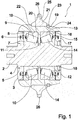
- Fig. 1 shows a sectional view of an embodiment of an embodiment of a cutting roller 1 for rock excavation in particular by a tunnel boring machine having a fixed cutting roller axis 2.
- the cutting roller axis 2 carries a collar-side cover 3, which abuts against an annular shoulder 4 formed in an end region of the cutting roller axis 2. Between the collar-side cover 3 and the annular shoulder 4, a sealing ring 5 is arranged.
- the collar-side cover 3 carries a portion of a ring sealing unit 6 which revolves around the cutting roll axis 2 and rests with a further portion radially outwardly of a first shaft bearing body 7 and abuts against a first seal carrier 8, the radially outside of the first Shaft bearing body 7 is arranged.
- a first cutting ring bearing body 9 is present, wherein between the first shaft bearing body 7 and the first cutting ring bearing body 9, a number of first bearing rollers 10 is arranged.
- the cutting roller axis 2 is surrounded by a compression ring 11, on the side facing away from the first shaft bearing body 7 a second shaft bearing body 12 is arranged, which surrounds the cutting roller axis 2 as the first shaft bearing body 7.
- a second cutting ring bearing body 13 is provided, wherein between the second shaft bearing body 12 and the second cutting ring bearing body 13, a number of second bearing rollers 14 is arranged.
- a second ring sealing unit 15 is arranged, which rests with a portion on the second shaft bearing body 12 and on a radially outside of the second Wollenlager stresses 12 arranged second seal carrier 16 is present, while another portion of the second ring sealing unit 15 in one on the side facing away from the upset ring 11 of the second wool storage body 12 arranged threaded cover 17 engages.
- the thread-side cover 17 can be screwed by means of an edge shaft nut 18 onto an external thread formed on the cutting roll axis 2, so that the abovementioned components are fixed in the axial direction.
- a roller body 19 is arranged with a radial Centering shoulder 20 pointing in the direction of the cutting roller axis 2 engages between the first cutting ring bearing body 9 and the second cutting ring bearing body 13 and is firmly connected to the first cutting ring bearing body 9 and the second cutting ring bearing body 13.
- the roller main body 19 is rotatable with respect to the cutting roller axis 2.
- an embodiment of a cutting ring 21 according to the invention is mounted, which in the embodiment according to Fig. 1 in the axial direction abuts against the roller body 19 circumferentially formed stop shoulder 22 and on the cutting ring stop shoulder 22 opposite side by a releasable locking ring 23, which in turn is arranged in a formed in the roller body 19 Sich ceremoniessringnut 24, fixed in the axial direction.
- the locking ring 23 is thus detachably formed by the roller body 19 such that after removal of the locking ring 23 of the cutting ring 21 in the embodiment according to Fig. 1 from the roller body 19 can be removed by pushing in the axial direction and thus interchangeable.
- the cutting ring 21 carries in a radially raised outer portion 25, a number of cutting inserts 26 made of a material harder with respect to the material of the cutting ring 21.
- Fig. 2 shows in an end view of the embodiment of a cutting roller 1 according to Fig. 1 , The representation according to Fig. 2 It can be seen that the cutting inserts 26 are arranged in the circumferential direction uniformly spaced over the entire circumference of the cutting ring 21, wherein between adjacent cutting ring inserts 26 each have a gutter portion 27 of the cutting ring 21 is present.
- FIG. 2 the illustration according to Fig. 2 infer that the cutting ring inserts 26 are arranged in the axial direction completely by the raised outer portion 25 of the cutting ring 21 extending Schneid disruptnuten 28 as cutting insert recordings and axially outside and at least in the new state radially outwardly flush with the gutter sections 27 of the cutting ring 21.
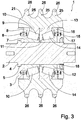
- Fig. 3 shows in a cross section a further embodiment of a cutting roller 1 for rock excavation in particular by a tunnel boring machine, wherein in the embodiment according to Fig. 1 and Fig. 2 as well as the execution according to Fig. 3 Corresponding elements provided with the same reference numerals and are not explained in detail to avoid repetition. Notwithstanding the execution of the cutting roller 1 according to Fig.1 and Fig. 2 has at the cutting roller 1 according to Fig. 3 the cutting ring 21 via three raised outer portions 25, each carrying a number of cutting sets 26. Furthermore, can the Representation according to Fig. 3 see that the cutting ring 21 solid and according to the roller body 19 in the embodiment according to Fig. 1 and Fig. 2 on the radial outer sides of the cover 3, 17, the seal carrier 8, 16 and the cutting ring bearing body 9, 13 is placed.
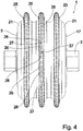
- Fig. 4 shows in an end view of the execution of the cutting roller 1, wherein the representation according to Fig. 4 can be seen that the cutting insert grooves 28 are arranged in the outer portions 25 so that in each case three cutting insert grooves 28 are aligned in different outer sections 25 in the axial direction with each other. This orientation is convenient for manufacturing reasons.
- Fig. 5 shows a side view of the embodiments of cutting rollers 1 according to Fig. 1 to Fig. 4 , From the illustration according to Fig. 5 It can be seen particularly clearly that the cutting inserts 26 are exposed axially on the outside.
- Fig. 6 shows in a detailed view of a cutting ring 21 according to the invention in the range of three cutting inserts 26 which are arranged in axially continuous cutting insert grooves 28 and spaced apart by gutter sections 27 of the cutting ring 21.
- the representation according to Fig. 6 It can be seen particularly clearly that the cutting inserts 26 are flush with their outer contour flush with the intermediate web sections 27, so that the risk of excessive singular stresses of the cutting inserts 26 due to protruding areas is excluded.
- Fig. 7 shows in a detailed sectional view of a number of cutting insert grooves 28 arranged cutting inserts 26.
- the illustration according to Fig. 7 can be seen that each Schneid disruptnut 28 is formed with a flat foot surface 29, to the On both sides in the circumferential direction of the cutting roller 21 rounded transition surfaces 30, 31 connect.
- the transition surfaces 30, 31 are continued on their side facing away from the foot surface 29 by turn planar radial side surfaces 32, 33 which each run to the center of the circle defined by the cutting ring 21.
- the cutting insert grooves 28 are provided with solder layers 38 which ensure a secure connection after appropriate heating of the cutting ring 21 in the area of the cutting insert grooves 28 and the cutting inserts 26.
- the cutting inserts 26 are fixed only with their peripheral outer sides, which are subject to relatively little wear. Furthermore, wear of the cutting ring 21 takes place essentially in the intermediate web sections 27, so that the cutting inserts 26 have a tooth structure form and protect the gutter sections 27 from further excessive wear.
Landscapes
- Engineering & Computer Science (AREA)
- Mining & Mineral Resources (AREA)
- Geology (AREA)
- Life Sciences & Earth Sciences (AREA)
- General Life Sciences & Earth Sciences (AREA)
- Geochemistry & Mineralogy (AREA)
- Mechanical Engineering (AREA)
- Physics & Mathematics (AREA)
- Environmental & Geological Engineering (AREA)
- Fluid Mechanics (AREA)
- Earth Drilling (AREA)
- Excavating Of Shafts Or Tunnels (AREA)
- Drilling And Exploitation, And Mining Machines And Methods (AREA)
- Turning (AREA)
Description
- Die Erfindung betrifft einen Schneidring einer Schneidrolle zum Gesteinsabbau gemäß dem Oberbegriff des Patentanspruches 1 sowie eine Schneidrolle zum Gesteinsabbau.
- Ein derartiger Schneidring ist aus
US 5 785 135 A bekannt. Der vorbekannte Schneidring für eine Schneidrolle zum Gesteinsabbau verfügt über eine Anzahl von Schneideinsätzen, die in Schneideinsatzaufnahmen angeordnet sind. Die Schneideinstatzaufnahmen sind als in axialer Richtung durchgehende Schneideinsatznuten ausgebildet, wobei die Schneideinsätze die Schneideinsatznuten vollständig ausfüllen. Die Schneideinsätze sind durch Presspassung befestigt und stehen in radialer Richtung zwischen benachbarten Schneideinsatznuten ausgebildeten Zwischenstegabschnitten über. - Ein weiterer Schneidring für eine Schneidrolle zum Gesteinsabbau ist aus
US 7,401,537 B1 bekannt. Dieser vorbekannte Schneidring ist mit durch Bohren als Löcher ausgebildete, umfänglich geschlossene Schneideinsatzaufnahmen ausgestattet. In den Schneideinsatzaufnahmen sind Schneideinsätze angeordnet, die durch eine Presspassung in den Schneideinsatzaufnahmen gehalten sind. Zwischen den Schneideinsätzen liegende Zwischenabschnitte sind über eine Laserbearbeitung gehärtet. - Der Erfindung liegt die Aufgabe zugrunde, einen Schneidring der eingangs genannten Art anzugeben, der sich bei einer verhältnismäßig einfachen Herstellung durch eine relativ lange Nutzungsdauer auszeichnet.
- Diese Aufgabe wird bei einem Schneidring der eingangs genannten Art erfindungsgemäß mit den kennzeichnenden Merkmalen des Patentanspruchs 1 gelöst.
- Dadurch, dass bei dem erfindungsgemäßen Schneidring die Schneideinsätze außenseitig bündig mit zwischen benachbarten Schneideinsatznuten ausgebildeten Zwischenabschnitten abschließen und über eine Lotschicht gehalten sind, ergibt sich zum einen ein einfaches Herstellen der Schneidrolle und eine relativ lange Nutzungsdauer durch ein in Umfangsrichtung konturfreies Ausbilden im Wechsel zwischen Schneidseinsätzen und Zwischenstegabschnitten.
- Weitere zweckmäßige Ausgestaltungen der Erfindung sind Gegenstand der Unteransprüche.
- Weitere zweckmäßige Ausgestaltungen und Vorteile der Erfindung ergeben sich aus der nachfolgenden Erläuterung von Ausführungsbeispielen mit Bezug auf die Figuren der Zeichnung.
- Es zeigen:
- Fig. 1
- in einer Schnittansicht eine Ausführung einer Schneidrolle zum Gesteinsabbau mit einem Ausführungsbeispiel eines erfindungsgemäßen Schneidringes,
- Fig. 2
- die Ausführung gemäß
Fig. 1 in einer Stirnansicht, - Fig.3
- in einer Schnittansicht eine weitere Ausführung einer Schneidrolle zum Gesteinsabbau mit einem weiteren Aus-führungsbeispiel eines erfindungsgemäßen Schneidringes,
- Fig. 4
- die Ausführung gemäß
Fig. 3 in einer Stirnansicht, - Fig. 5
- die Ausführung gemäß
Fig. 1 beziehungsweise gemäßFig. 3 in einer Seitenansicht, - Fig. 6
- in einem vergrößerten Ausschnitt eine Stirnansicht auf ein Ausführungsbeispiel eines erfindungsgemäßen Schneidrin-ges, und
- Fig. 7
- in einer vergrößerten Schnittansicht das Ausführungsbei-spiel gemäß
Fig. 6 . -
Fig. 1 zeigt in einer Schnittansicht ein Ausführungsbeispiel einer Ausführung einer Schneidrolle 1 zum Gesteinsabbau insbesondere durch eine Tunnelvortriebsmaschine, die eine feststehende Schneidrollenachse 2 aufweist. Die Schneidrollenachse 2 trägt einen bundseitigen Deckel 3, der gegen eine in einem Endbereich der Schneidrollenachse 2 ausgebildete Ringschulter 4 anschlägt. Zwischen dem bundseitigen Deckel 3 und der Ringschulter 4 ist ein Dichtring 5 angeordnet. In einem radialen Abstand von der Schneidrollenachse 2 trägt der bundseitige Deckel 3 einen Abschnitt einer Ringdichteinheit 6, die um die Schneidrollenachse 2 umläuft und mit einem weiteren Abschnitt radial außenseitig eines ersten Wellenlagerkörpers 7 aufliegt und gegen einen ersten Dichtungsträger 8 anliegt, der radial außenseitig des ersten Wellenlagerkörpers 7 angeordnet ist. In einem radialen Abstand von dem ersten Wellenlagerkörper 7 ist ein erster Schneidringlagerkörper 9 vorhanden, wobei zwischen dem ersten Wellenlagerkörper 7 und dem ersten Schneidringlagerkörper 9 eine Anzahl von ersten Lagerwalzen 10 angeordnet ist. - Auf der dem bundseitigen Deckel 3 abgewandten Seite des ersten Wellenlagerkörpers 7 ist die Schneidrollenachse 2 von einem Stauchring 11 umschlossen, auf dessen dem ersten Wellenlagerkörper 7 abgewandten Seite ein zweiter Wellenlagerkörper 12 angeordnet ist, der wie der erste Wellenlagerkörper 7 die Schneidrollenachse 2 umschließt.
- In einem radialen Abstand von dem zweiten Wellenlagerkörper 12 ist ein zweiter Schneidringlagerkörper 13 vorhanden, wobei zwischen dem zweiten Wellenlagerkörper 12 und dem zweiten Schneidringlagerkörper 13 eine Anzahl von zweiten Lagerwalzen 14 angeordnet ist. Auf der dem Stauchring 11 abgewandten Seite des zweiten Wellenlagerkörpers 12 ist eine zweite Ringdichteinheit 15 angeordnet, die mit einem Abschnitt auf dem zweiten Wellenlagerkörper 12 aufliegt sowie an einem radial außenseitig des zweiten Wollenlagerkörpers 12 angeordneten zweiten Dichtungsträger 16 anliegt, während ein weiterer Abschnitt der zweiten Ringdichteinheit 15 in einen auf der dem Stauchring 11 abgewandten Seite des zweiten Wollenlagerkörpers 12 angeordneten gewindeseitigen Deckel 17 eingreift. Der gewindeseitige Deckel 17 ist mittels einer Randwellenmutter 18 auf ein an der Schneidrollenachse 2 ausgebildetes Außengewinde aufschraubbar, so dass die vorgenannten Komponenten in axialer Richtung fixiert sind.
- Weiterhin lässt sich der Darstellung gemäß
Fig. 1 entnehmen, dass auf den nach radial außen gewandten Seiten des ersten bundseitigen Deckels 3, des ersten Dichtungsträgers 8, des ersten Schneidringlagerkörpers 9, des zweiten Schneidringlagerkörpers 13, des zweiten Dichtungsträgers 16 und des gewindeseitigen Deckels 17 ein Rollengrundkörper 19 angeordnet ist, der mit einer radial in Richtung der Schneidrollenachse 2 weisenden Zentrierschulter 20 zwischen dem ersten Schneidringlagerkörper 9 und dem zweiten Schneidringlagerkörper 13 eingreift sowie fest mit dem ersten Schneidringlagerkörper 9 und dem zweiten Schneidringlagerkörper 13 verbunden ist. Dadurch ist der Rollengrundkörper 19 in Bezug auf die Schneidrollenachse 2 drehbar. - Auf der der Schneidrollenachse 2 in radialer Richtung abgewandten Seite des Rollengrundkörpers 19 ist ein Ausführungsbeispiel eines erfindungsgemäßen Schneidringes 21 angebracht, der bei der Ausführung gemäß
Fig. 1 in axialer Richtung an einer an dem Rollengrundkörper 19 umlaufend ausgebildeten Anschlagschulter 22 anliegt und auf der der Schneidringanschlagschulter 22 gegenüberliegenden Seite durch einen lösbaren Sicherungsring 23, der selbst wiederum in einer in dem Rollengrundkörper 19 ausgebildeten Sicherungsringnut 24 angeordnet ist, in axialer Richtung fixiert ist. Der Sicherungsring 23 ist somit von dem Rollengrundkörper 19 derart lösbar ausgebildet, dass nach Entfernen des Sicherungsringes 23 der Schneidring 21 in dem Ausführungsbeispiel gemäßFig. 1 von dem Rollengrundkörper 19 durch Abschieben in axialer Richtung entfernbar und damit auswechselbar ist. - Der Schneidring 21 trägt in einem radialen erhabenen Außenabschnitt 25 eine Anzahl von Schneideinsätzen 26 aus einem gegenüber dem Material des Schneidringes 21 härteren Material.
-
Fig. 2 zeigt in einer Stirnansicht das Ausführungsbeispiel einer Schneidrolle 1 gemäßFig. 1 . Der Darstellung gemäßFig. 2 lässt sich entnehmen, dass die Schneideinsätze 26 in Umfangsrichtung gleichmäßig beabstandet über den gesamten Umfang des Schneidringes 21 angeordnet sind, wobei zwischen benachbarten Schneidringeinsätzen 26 jeweils ein Zwischenstegabschnitt 27 des Schneidringes 21 vorhanden ist. - Weiterhin lässt sich der Darstellung gemäß
Fig. 2 entnehmen, dass die Schneidringeinsätze 26 sich in axialer Richtung vollständig durch den erhabenen Außenabschnitt 25 des Schneidringes 21 erstreckenden Schneideinsatznuten 28 als Schneideinsatzaufnahmen angeordnet sind und axial außenseitig sowie jedenfalls im Neuzustand radial außenseitig bündig mit den Zwischenstegabschnitten 27 des Schneidringes 21 abschließen. -
Fig. 3 zeigt in einem Querschnitt eine weitere Ausführung einer Schneidrolle 1 zum Gesteinsabbau insbesondere durch eine Tunnelvortriebsmaschine, wobei sich bei der Ausführung gemäßFig. 1 undFig. 2 sowie der Ausführung gemäßFig. 3 einander entsprechende Elemente mit den gleichen Bezugszeichen versehen und zum Vermeiden von Wiederholungen im Weiteren nicht näher erläutert sind. Abweichend von der Ausführung der Schneidrolle 1 gemäßFig.1 undFig. 2 verfügt bei der Schneidrolle 1 gemäßFig. 3 der Schneidring 21 über drei erhabene Außenabschnitte 25, die jeweils eine Anzahl von Schneidsätzen 26 tragen. Weiterhin lässt sich der Darstellung gemäßFig. 3 entnehmen, dass der Schneidring 21 massiv ausgebildet und entsprechend dem Rollengrundkörper 19 bei der Ausführung gemäßFig. 1 undFig. 2 auf die radialen Außenseiten der Deckel 3, 17, der Dichtungsträger 8, 16 sowie der Schneidringlagerkörper 9, 13 aufgesetzt ist. -
Fig. 4 zeigt in einer Stirnansicht die Ausführung der Schneidrolle 1, wobei sich der Darstellung gemäßFig. 4 entnehmen lässt, dass die Schneideinsatznuten 28 in den Außenabschnitten 25 so angeordnet sind, dass jeweils drei Schneideinsatznuten 28 in verschiedenen Außenabschnitten 25 in axialer Richtung miteinander fluchten. Diese Ausrichtung ist aus Herstellungsgründen zweckmäßig. -
Fig. 5 zeigt in einer Seitenansicht die Ausführungsbeispiele von Schneidrollen 1 gemäßFig. 1 bis Fig. 4 . Aus der Darstellung gemäßFig. 5 lässt sich besonders deutlich entnehmen, dass die Schneideinsätze 26 axial außenseitig freiliegen. -
Fig. 6 zeigt in einer Detailansicht einen erfindungsgemäßen Schneidring 21 im Bereich von drei Schneideinsätzen 26, die in in axialer Richtung durchgehenden Schneideinsatznuten 28 angeordnet und durch Zwischenstegabschnitte 27 des Schneidringes 21 voneinander beabstandet sind. Der Darstellung gemäßFig. 6 lässt sich besonders deutlich entnehmen, dass die Schneideinsätze 26 mit ihrer Außenkontur bündig mit den Zwischenstegabschnitten 27 abschließen, so dass die Gefahr von übermäßigen singulären Beanspruchungen der Schneideinsätze 26 aufgrund überstehender Bereiche ausgeschlossen ist. -
Fig. 7 zeigt in einer detaillierten Schnittansicht eine Anzahl von in Schneideinsatznuten 28 angeordneten Schneideinsätzen 26. Der Darstellung gemäßFig. 7 lässt sich entnehmen, dass jede Schneideinsatznut 28 mit einer planen Fußfläche 29 ausgebildet ist, an die sich beidseitig in Umfangsrichtung der Schneidrolle 21 abgerundete Übergangsflächen 30, 31 anschließen. Die Übergangsflächen 30, 31 sind auf ihrer der Fußfläche 29 abgewandten Seite durch wiederum plane Radialseitenflächen 32, 33 fortgesetzt, die jeweils auf den Mittelpunkt des durch den Schneidring 21 definierten Kreises zulaufen. - An den den Übergangsflächen 30, 31 abgewandten Enden der Radialseitenflächen 32, 33 sind Ringstufenflächen 34, 35 ausgebildet, die sich in Umfangsrichtung der Schneidrolle 21 nach außen erstrecken. An die in Umfangsrichtung außen liegenden Enden der Ringstufenflächen 34, 35 schließen sich Keilseitenflächen 36, 37 an, die sich in radialer Richtung bis zu der radialen Außenseite des Schneidringes 21 erstrecken. Die Keilseitenflächen 36, 37 einer Schneideinsatznut 28 sind von radial innen nach radial außen aufeinander zu geneigt ausgerichtet, so dass ein in axialer Richtung in die Schneideinsatznut 28 eingeschobener, komplementär zu den Schneideinsatznuten 28 geformter Schneideinsatz 26 in radialer Richtung des Schneidringes 21 gehalten ist.
- Zum betriebssicheren Befestigen der Schneideinsätze 26 in den Schneideinsatznuten 28 sind die Schneideinsatznuten 28 auskleidende Lotschichten 38 vorgesehen, die nach entsprechendem Erwärmen des Schneidringes 21 im Bereich der Schneideinsatznuten 28 sowie der Schneideinsätze 26 eine sichere Verbindung gewährleisten.
- Im Betrieb der Schneidrolle 1 ergibt sich bei der Erfindung insbesondere der Vorteil, dass die Schneideinsätze 26 nur mit ihren in Umfangsrichtung liegenden Außenseiten befestigt sind, welche einem relativ geringen Verschleiß unterliegen. Des weiteren erfolgt ein Verschleiß des Schneidringes 21 im Wesentlichen in den Zwischenstegabschnitten 27, so dass die Schneideinsätze 26 eine Zahnstruktur bilden und die Zwischenstegabschnitte 27 vor weiterem übermäßigem Verschleiß schützen.
Claims (4)
- Schneidring für eine Schneidrolle (1) zum Gesteinsabbau mit einer Anzahl von Schneideinsätzen (26), die in Schneideinsatzaufnahmen (28) angeordnet sind, wobei die Schneideinsatzaufnahmen als in axialer Richtung durchgehende Schneideinsatznuten (28) ausgebildet sind und wobei die Schneideinsätze (26) die Schneideinsatznuten (28) vollständig ausfüllen, dadurch gekennzeichnet, dass die Schneideinsätze (26) außenseitig bündig mit zwischen benachbarten Schneideinsatznuten (28) ausgebildeten Zwischenstegabschnitten (27) abschließen und dass zwischen jedem Schneideinsatz (26) sowie jeder Schneideinsatznut (28) eine Lotschicht vorhanden ist
- Schneidring nach Anspruch 1 , dadurch gekennzeichnet, dass die Schneideinsätze (26) in einem erhabenen Außenabschnitt (25) angeordnet sind.
- Schneidring nach Anspruch 1 oder Anspruch 2, dadurch gekennzeichnet, dass jede Schneideinsatznut (28) Keileinsatzflächen (36, 37) aufweist, die von radial innen nach radial außen aufeinander zu geneigt sind.
- Schneidrolle zum Gesteinsabbau, die mit wenigstens einem Schneidring (21) nach einem der Ansprüche 1 bis 3 ausgestattet ist.
Applications Claiming Priority (2)
| Application Number | Priority Date | Filing Date | Title |
|---|---|---|---|
| DE102012220434.2A DE102012220434A1 (de) | 2012-11-09 | 2012-11-09 | Schneidring für eine Schneidrolle zum Gesteinsabbau und Schneidrolle zum Gesteinsabbau |
| PCT/EP2013/071054 WO2014072146A2 (de) | 2012-11-09 | 2013-10-09 | Schneidring für eine schneidrolle zum gesteinsabbau und schneidrolle zum gesteinsabbau |
Publications (2)
| Publication Number | Publication Date |
|---|---|
| EP2917487A2 EP2917487A2 (de) | 2015-09-16 |
| EP2917487B1 true EP2917487B1 (de) | 2017-06-21 |
Family
ID=49378253
Family Applications (1)
| Application Number | Title | Priority Date | Filing Date |
|---|---|---|---|
| EP13777003.8A Active EP2917487B1 (de) | 2012-11-09 | 2013-10-09 | Schneidring für eine schneidrolle zum gesteinsabbau und schneidrolle zum gesteinsabbau |
Country Status (7)
| Country | Link |
|---|---|
| US (1) | US20150285073A1 (de) |
| EP (1) | EP2917487B1 (de) |
| JP (1) | JP2015535557A (de) |
| AU (1) | AU2013343775A1 (de) |
| CA (1) | CA2886925A1 (de) |
| DE (1) | DE102012220434A1 (de) |
| WO (1) | WO2014072146A2 (de) |
Families Citing this family (4)
| Publication number | Priority date | Publication date | Assignee | Title |
|---|---|---|---|---|
| DE102017205756A1 (de) | 2017-04-04 | 2018-10-04 | Implenia Construction GmbH | Schneidrolle |
| CN108115849A (zh) * | 2017-12-04 | 2018-06-05 | 太原理工大学 | 一种小孔道内预制裂缝切割装置 |
| DE102018005972A1 (de) | 2018-07-20 | 2020-01-23 | Hydac Technology Gmbh | Schneidrolle |
| DE102021102833A1 (de) * | 2021-02-08 | 2022-08-11 | Aktiebolaget Skf | Schneidringanordnung |
Family Cites Families (10)
| Publication number | Priority date | Publication date | Assignee | Title |
|---|---|---|---|---|
| US816768A (en) * | 1905-11-11 | 1906-04-03 | Harriet M Young | Stone-cutting saw. |
| US2121202A (en) * | 1935-03-19 | 1938-06-21 | Robert J Killgore | Rotary bit |
| ZA723776B (en) * | 1972-06-02 | 1974-01-30 | Hard Metals Ltd | Disc cutting unit for use on rock boring machines |
| ZA744897B (en) * | 1974-07-31 | 1976-05-26 | Board Hardmetal Proprietary Lt | Improvements in or relating to disc cutting units for use on rock boring machines |
| JPS6225699A (ja) * | 1985-07-26 | 1987-02-03 | 日立造船株式会社 | 刃付部材及びその製作方法 |
| US5785135B1 (en) * | 1996-10-03 | 2000-05-02 | Baker Hughes Inc | Earth-boring bit having cutter with replaceable kerf ring with contoured inserts |
| JPH11223090A (ja) * | 1998-02-05 | 1999-08-17 | Toshiba Tungaloy Co Ltd | 掘削用のカッタリング及び掘削用のディスクカッタ |
| JP2000064789A (ja) * | 1998-08-26 | 2000-02-29 | Mitsubishi Materials Corp | ローラーカッタ |
| JP2004122300A (ja) * | 2002-10-03 | 2004-04-22 | Tenryu Saw Mfg Co Ltd | 回転鋸 |
| US7401537B1 (en) | 2004-03-23 | 2008-07-22 | David Krauter | Cutter insert gum modification method and apparatus |
-
2012
- 2012-11-09 DE DE102012220434.2A patent/DE102012220434A1/de not_active Withdrawn
-
2013
- 2013-10-09 US US14/437,094 patent/US20150285073A1/en not_active Abandoned
- 2013-10-09 AU AU2013343775A patent/AU2013343775A1/en not_active Abandoned
- 2013-10-09 CA CA2886925A patent/CA2886925A1/en not_active Abandoned
- 2013-10-09 EP EP13777003.8A patent/EP2917487B1/de active Active
- 2013-10-09 JP JP2015541062A patent/JP2015535557A/ja active Pending
- 2013-10-09 WO PCT/EP2013/071054 patent/WO2014072146A2/de not_active Ceased
Non-Patent Citations (1)
| Title |
|---|
| None * |
Also Published As
| Publication number | Publication date |
|---|---|
| WO2014072146A3 (de) | 2014-11-20 |
| EP2917487A2 (de) | 2015-09-16 |
| AU2013343775A1 (en) | 2015-04-23 |
| WO2014072146A2 (de) | 2014-05-15 |
| DE102012220434A1 (de) | 2014-06-12 |
| CA2886925A1 (en) | 2014-05-15 |
| US20150285073A1 (en) | 2015-10-08 |
| JP2015535557A (ja) | 2015-12-14 |
Similar Documents
| Publication | Publication Date | Title |
|---|---|---|
| EP2197613B1 (de) | Rundlaufwerkzeug, insbesondere bohrer | |
| DE102013220884B4 (de) | Modulares Trägerwerkzeug sowie Werkzeugkopf | |
| EP2934801B1 (de) | Werkzeughalter und zerspanwerkzeug mit dämpfungssystem | |
| DE2517613C3 (de) | Bohrlochwerkzeug sowie Verfahren zum Befestigen und Lösen eines Bohrlochwerkzeugs auf bzw. von einem Bohrgestänge | |
| DE112011104493B4 (de) | Drehbares Leitrad für ein Unterwagensystem eines Kettenfahrzeugs | |
| DE102008060374A1 (de) | Dämpfungshülse | |
| DE102014014094A1 (de) | Meißeleinrichtung und verschleißgeschützter Meißel für eine Bodenfräsmaschine | |
| AT518983A4 (de) | VORRICHTUNG ZUM ENTWÄSSERN VON SCHÜTTFÄHIGEM ODER FLIEßFÄHIGEM AUFGABEGUT | |
| DE202012008997U1 (de) | Kolbeneinheit eines Arbeitszylinders | |
| DE102014013210A1 (de) | Zerspanwerkzeug mit einem Kühlkanal | |
| DE102015220777A1 (de) | Werkzeugkupplung zwischen zwei Kupplungsteilen sowie Kupplungsteil für eine solche Werkzeugkupplung | |
| DE102018205938A1 (de) | Bohrwerkzeug mit verbesserter Schmierung | |
| EP2917487A2 (de) | Schneidring für eine schneidrolle zum gesteinsabbau und schneidrolle zum gesteinsabbau | |
| DE102016117104A1 (de) | Mehrteiliges, gefedertes Schienenrad | |
| DE102009027732A1 (de) | Meißel einer Fräseinrichtung | |
| EP4006233B1 (de) | Walzenwerkzeug für eine bodenbearbeitungswalze | |
| DE102013226454B4 (de) | Verbindungsprinzip eines mehrteiligen Rotors für einen hydraulischen Nockenwellenversteller | |
| DE4431960C1 (de) | Messer für Fleischwölfe | |
| DE102019104105B3 (de) | Mahlgarnitursegment | |
| WO2017108461A1 (de) | Bohrkrone mit einem wellenförmigen bohrschaft | |
| AT526440B1 (de) | Verfahren zur Herstellung einer Antriebskomponente | |
| DE102011082732A1 (de) | Bohrwerkzeug mit Zentrierelement | |
| EP2535621B1 (de) | Wellendichtungsring für ein Sperröldichtungssystem eines wasserstoffgekühlten Generators | |
| DE102009018297A1 (de) | Kolbensystem zum Abdichten eines in einem Zylinder geführten Kolbens | |
| DE102017104649A1 (de) | Meißelanordnung und Verfahren zum Lagern eines Rundschaftmeißels |
Legal Events
| Date | Code | Title | Description |
|---|---|---|---|
| PUAI | Public reference made under article 153(3) epc to a published international application that has entered the european phase |
Free format text: ORIGINAL CODE: 0009012 |
|
| 17P | Request for examination filed |
Effective date: 20150529 |
|
| AK | Designated contracting states |
Kind code of ref document: A2 Designated state(s): AL AT BE BG CH CY CZ DE DK EE ES FI FR GB GR HR HU IE IS IT LI LT LU LV MC MK MT NL NO PL PT RO RS SE SI SK SM TR |
|
| AX | Request for extension of the european patent |
Extension state: BA ME |
|
| DAX | Request for extension of the european patent (deleted) | ||
| GRAP | Despatch of communication of intention to grant a patent |
Free format text: ORIGINAL CODE: EPIDOSNIGR1 |
|
| STAA | Information on the status of an ep patent application or granted ep patent |
Free format text: STATUS: GRANT OF PATENT IS INTENDED |
|
| RIC1 | Information provided on ipc code assigned before grant |
Ipc: E21B 10/12 20060101ALI20170116BHEP Ipc: E21C 25/18 20060101AFI20170116BHEP |
|
| INTG | Intention to grant announced |
Effective date: 20170216 |
|
| GRAS | Grant fee paid |
Free format text: ORIGINAL CODE: EPIDOSNIGR3 |
|
| GRAA | (expected) grant |
Free format text: ORIGINAL CODE: 0009210 |
|
| STAA | Information on the status of an ep patent application or granted ep patent |
Free format text: STATUS: THE PATENT HAS BEEN GRANTED |
|
| AK | Designated contracting states |
Kind code of ref document: B1 Designated state(s): AL AT BE BG CH CY CZ DE DK EE ES FI FR GB GR HR HU IE IS IT LI LT LU LV MC MK MT NL NO PL PT RO RS SE SI SK SM TR |
|
| REG | Reference to a national code |
Ref country code: GB Ref legal event code: FG4D Free format text: NOT ENGLISH |
|
| REG | Reference to a national code |
Ref country code: CH Ref legal event code: EP |
|
| REG | Reference to a national code |
Ref country code: IE Ref legal event code: FG4D Free format text: LANGUAGE OF EP DOCUMENT: GERMAN |
|
| REG | Reference to a national code |
Ref country code: AT Ref legal event code: REF Ref document number: 903126 Country of ref document: AT Kind code of ref document: T Effective date: 20170715 |
|
| REG | Reference to a national code |
Ref country code: DE Ref legal event code: R096 Ref document number: 502013007569 Country of ref document: DE |
|
| REG | Reference to a national code |
Ref country code: SE Ref legal event code: TRGR |
|
| REG | Reference to a national code |
Ref country code: FR Ref legal event code: PLFP Year of fee payment: 5 |
|
| REG | Reference to a national code |
Ref country code: NL Ref legal event code: MP Effective date: 20170621 |
|
| PG25 | Lapsed in a contracting state [announced via postgrant information from national office to epo] |
Ref country code: LT Free format text: LAPSE BECAUSE OF FAILURE TO SUBMIT A TRANSLATION OF THE DESCRIPTION OR TO PAY THE FEE WITHIN THE PRESCRIBED TIME-LIMIT Effective date: 20170621 Ref country code: HR Free format text: LAPSE BECAUSE OF FAILURE TO SUBMIT A TRANSLATION OF THE DESCRIPTION OR TO PAY THE FEE WITHIN THE PRESCRIBED TIME-LIMIT Effective date: 20170621 Ref country code: NO Free format text: LAPSE BECAUSE OF FAILURE TO SUBMIT A TRANSLATION OF THE DESCRIPTION OR TO PAY THE FEE WITHIN THE PRESCRIBED TIME-LIMIT Effective date: 20170921 Ref country code: FI Free format text: LAPSE BECAUSE OF FAILURE TO SUBMIT A TRANSLATION OF THE DESCRIPTION OR TO PAY THE FEE WITHIN THE PRESCRIBED TIME-LIMIT Effective date: 20170621 Ref country code: GR Free format text: LAPSE BECAUSE OF FAILURE TO SUBMIT A TRANSLATION OF THE DESCRIPTION OR TO PAY THE FEE WITHIN THE PRESCRIBED TIME-LIMIT Effective date: 20170922 |
|
| REG | Reference to a national code |
Ref country code: LT Ref legal event code: MG4D |
|
| PG25 | Lapsed in a contracting state [announced via postgrant information from national office to epo] |
Ref country code: NL Free format text: LAPSE BECAUSE OF FAILURE TO SUBMIT A TRANSLATION OF THE DESCRIPTION OR TO PAY THE FEE WITHIN THE PRESCRIBED TIME-LIMIT Effective date: 20170621 Ref country code: RS Free format text: LAPSE BECAUSE OF FAILURE TO SUBMIT A TRANSLATION OF THE DESCRIPTION OR TO PAY THE FEE WITHIN THE PRESCRIBED TIME-LIMIT Effective date: 20170621 Ref country code: BG Free format text: LAPSE BECAUSE OF FAILURE TO SUBMIT A TRANSLATION OF THE DESCRIPTION OR TO PAY THE FEE WITHIN THE PRESCRIBED TIME-LIMIT Effective date: 20170921 Ref country code: LV Free format text: LAPSE BECAUSE OF FAILURE TO SUBMIT A TRANSLATION OF THE DESCRIPTION OR TO PAY THE FEE WITHIN THE PRESCRIBED TIME-LIMIT Effective date: 20170621 |
|
| PG25 | Lapsed in a contracting state [announced via postgrant information from national office to epo] |
Ref country code: SK Free format text: LAPSE BECAUSE OF FAILURE TO SUBMIT A TRANSLATION OF THE DESCRIPTION OR TO PAY THE FEE WITHIN THE PRESCRIBED TIME-LIMIT Effective date: 20170621 Ref country code: CZ Free format text: LAPSE BECAUSE OF FAILURE TO SUBMIT A TRANSLATION OF THE DESCRIPTION OR TO PAY THE FEE WITHIN THE PRESCRIBED TIME-LIMIT Effective date: 20170621 Ref country code: RO Free format text: LAPSE BECAUSE OF FAILURE TO SUBMIT A TRANSLATION OF THE DESCRIPTION OR TO PAY THE FEE WITHIN THE PRESCRIBED TIME-LIMIT Effective date: 20170621 Ref country code: EE Free format text: LAPSE BECAUSE OF FAILURE TO SUBMIT A TRANSLATION OF THE DESCRIPTION OR TO PAY THE FEE WITHIN THE PRESCRIBED TIME-LIMIT Effective date: 20170621 |
|
| PG25 | Lapsed in a contracting state [announced via postgrant information from national office to epo] |
Ref country code: ES Free format text: LAPSE BECAUSE OF FAILURE TO SUBMIT A TRANSLATION OF THE DESCRIPTION OR TO PAY THE FEE WITHIN THE PRESCRIBED TIME-LIMIT Effective date: 20170621 Ref country code: PL Free format text: LAPSE BECAUSE OF FAILURE TO SUBMIT A TRANSLATION OF THE DESCRIPTION OR TO PAY THE FEE WITHIN THE PRESCRIBED TIME-LIMIT Effective date: 20170621 Ref country code: SM Free format text: LAPSE BECAUSE OF FAILURE TO SUBMIT A TRANSLATION OF THE DESCRIPTION OR TO PAY THE FEE WITHIN THE PRESCRIBED TIME-LIMIT Effective date: 20170621 Ref country code: IS Free format text: LAPSE BECAUSE OF FAILURE TO SUBMIT A TRANSLATION OF THE DESCRIPTION OR TO PAY THE FEE WITHIN THE PRESCRIBED TIME-LIMIT Effective date: 20171021 |
|
| REG | Reference to a national code |
Ref country code: DE Ref legal event code: R097 Ref document number: 502013007569 Country of ref document: DE |
|
| PLBE | No opposition filed within time limit |
Free format text: ORIGINAL CODE: 0009261 |
|
| STAA | Information on the status of an ep patent application or granted ep patent |
Free format text: STATUS: NO OPPOSITION FILED WITHIN TIME LIMIT |
|
| PG25 | Lapsed in a contracting state [announced via postgrant information from national office to epo] |
Ref country code: DK Free format text: LAPSE BECAUSE OF FAILURE TO SUBMIT A TRANSLATION OF THE DESCRIPTION OR TO PAY THE FEE WITHIN THE PRESCRIBED TIME-LIMIT Effective date: 20170621 |
|
| 26N | No opposition filed |
Effective date: 20180322 |
|
| PG25 | Lapsed in a contracting state [announced via postgrant information from national office to epo] |
Ref country code: MC Free format text: LAPSE BECAUSE OF FAILURE TO SUBMIT A TRANSLATION OF THE DESCRIPTION OR TO PAY THE FEE WITHIN THE PRESCRIBED TIME-LIMIT Effective date: 20170621 |
|
| REG | Reference to a national code |
Ref country code: CH Ref legal event code: PL |
|
| REG | Reference to a national code |
Ref country code: IE Ref legal event code: MM4A |
|
| PG25 | Lapsed in a contracting state [announced via postgrant information from national office to epo] |
Ref country code: LU Free format text: LAPSE BECAUSE OF NON-PAYMENT OF DUE FEES Effective date: 20171009 Ref country code: CH Free format text: LAPSE BECAUSE OF NON-PAYMENT OF DUE FEES Effective date: 20171031 Ref country code: LI Free format text: LAPSE BECAUSE OF NON-PAYMENT OF DUE FEES Effective date: 20171031 |
|
| REG | Reference to a national code |
Ref country code: BE Ref legal event code: MM Effective date: 20171031 |
|
| PG25 | Lapsed in a contracting state [announced via postgrant information from national office to epo] |
Ref country code: SI Free format text: LAPSE BECAUSE OF FAILURE TO SUBMIT A TRANSLATION OF THE DESCRIPTION OR TO PAY THE FEE WITHIN THE PRESCRIBED TIME-LIMIT Effective date: 20170621 Ref country code: BE Free format text: LAPSE BECAUSE OF NON-PAYMENT OF DUE FEES Effective date: 20171031 |
|
| PG25 | Lapsed in a contracting state [announced via postgrant information from national office to epo] |
Ref country code: MT Free format text: LAPSE BECAUSE OF FAILURE TO SUBMIT A TRANSLATION OF THE DESCRIPTION OR TO PAY THE FEE WITHIN THE PRESCRIBED TIME-LIMIT Effective date: 20170621 |
|
| REG | Reference to a national code |
Ref country code: FR Ref legal event code: PLFP Year of fee payment: 6 |
|
| PG25 | Lapsed in a contracting state [announced via postgrant information from national office to epo] |
Ref country code: IE Free format text: LAPSE BECAUSE OF NON-PAYMENT OF DUE FEES Effective date: 20171009 |
|
| PG25 | Lapsed in a contracting state [announced via postgrant information from national office to epo] |
Ref country code: HU Free format text: LAPSE BECAUSE OF FAILURE TO SUBMIT A TRANSLATION OF THE DESCRIPTION OR TO PAY THE FEE WITHIN THE PRESCRIBED TIME-LIMIT; INVALID AB INITIO Effective date: 20131009 |
|
| PG25 | Lapsed in a contracting state [announced via postgrant information from national office to epo] |
Ref country code: CY Free format text: LAPSE BECAUSE OF FAILURE TO SUBMIT A TRANSLATION OF THE DESCRIPTION OR TO PAY THE FEE WITHIN THE PRESCRIBED TIME-LIMIT Effective date: 20170621 |
|
| PG25 | Lapsed in a contracting state [announced via postgrant information from national office to epo] |
Ref country code: MK Free format text: LAPSE BECAUSE OF FAILURE TO SUBMIT A TRANSLATION OF THE DESCRIPTION OR TO PAY THE FEE WITHIN THE PRESCRIBED TIME-LIMIT Effective date: 20170621 |
|
| REG | Reference to a national code |
Ref country code: AT Ref legal event code: MM01 Ref document number: 903126 Country of ref document: AT Kind code of ref document: T Effective date: 20181009 |
|
| PG25 | Lapsed in a contracting state [announced via postgrant information from national office to epo] |
Ref country code: AT Free format text: LAPSE BECAUSE OF NON-PAYMENT OF DUE FEES Effective date: 20181009 |
|
| PG25 | Lapsed in a contracting state [announced via postgrant information from national office to epo] |
Ref country code: PT Free format text: LAPSE BECAUSE OF FAILURE TO SUBMIT A TRANSLATION OF THE DESCRIPTION OR TO PAY THE FEE WITHIN THE PRESCRIBED TIME-LIMIT Effective date: 20170621 |
|
| PG25 | Lapsed in a contracting state [announced via postgrant information from national office to epo] |
Ref country code: AL Free format text: LAPSE BECAUSE OF FAILURE TO SUBMIT A TRANSLATION OF THE DESCRIPTION OR TO PAY THE FEE WITHIN THE PRESCRIBED TIME-LIMIT Effective date: 20170621 |
|
| PGFP | Annual fee paid to national office [announced via postgrant information from national office to epo] |
Ref country code: SE Payment date: 20211021 Year of fee payment: 9 Ref country code: GB Payment date: 20211022 Year of fee payment: 9 |
|
| PGFP | Annual fee paid to national office [announced via postgrant information from national office to epo] |
Ref country code: FR Payment date: 20211022 Year of fee payment: 9 |
|
| REG | Reference to a national code |
Ref country code: SE Ref legal event code: EUG |
|
| GBPC | Gb: european patent ceased through non-payment of renewal fee |
Effective date: 20221009 |
|
| PG25 | Lapsed in a contracting state [announced via postgrant information from national office to epo] |
Ref country code: FR Free format text: LAPSE BECAUSE OF NON-PAYMENT OF DUE FEES Effective date: 20221031 |
|
| PG25 | Lapsed in a contracting state [announced via postgrant information from national office to epo] |
Ref country code: SE Free format text: LAPSE BECAUSE OF NON-PAYMENT OF DUE FEES Effective date: 20221010 |
|
| PG25 | Lapsed in a contracting state [announced via postgrant information from national office to epo] |
Ref country code: GB Free format text: LAPSE BECAUSE OF NON-PAYMENT OF DUE FEES Effective date: 20221009 |
|
| PGFP | Annual fee paid to national office [announced via postgrant information from national office to epo] |
Ref country code: TR Payment date: 20231002 Year of fee payment: 11 Ref country code: IT Payment date: 20231031 Year of fee payment: 11 |
|
| PG25 | Lapsed in a contracting state [announced via postgrant information from national office to epo] |
Ref country code: IT Free format text: LAPSE BECAUSE OF NON-PAYMENT OF DUE FEES Effective date: 20241009 |
|
| PGFP | Annual fee paid to national office [announced via postgrant information from national office to epo] |
Ref country code: DE Payment date: 20251009 Year of fee payment: 13 |
|
| REG | Reference to a national code |
Ref country code: DE Ref legal event code: R082 Ref document number: 502013007569 Country of ref document: DE Representative=s name: MAUCHER JENKINS PATENTANWAELTE & RECHTSANWAELT, DE |