EP2913620B1 - Handfeuerwaffe mit Verschlusshebel - Google Patents
Handfeuerwaffe mit Verschlusshebel Download PDFInfo
- Publication number
- EP2913620B1 EP2913620B1 EP15155524.0A EP15155524A EP2913620B1 EP 2913620 B1 EP2913620 B1 EP 2913620B1 EP 15155524 A EP15155524 A EP 15155524A EP 2913620 B1 EP2913620 B1 EP 2913620B1
- Authority
- EP
- European Patent Office
- Prior art keywords
- detent
- lever
- locking
- counter
- firearm according
- Prior art date
- Legal status (The legal status is an assumption and is not a legal conclusion. Google has not performed a legal analysis and makes no representation as to the accuracy of the status listed.)
- Active
Links
Images

Classifications
-
- F—MECHANICAL ENGINEERING; LIGHTING; HEATING; WEAPONS; BLASTING
- F41—WEAPONS
- F41A—FUNCTIONAL FEATURES OR DETAILS COMMON TO BOTH SMALLARMS AND ORDNANCE, e.g. CANNONS; MOUNTINGS FOR SMALLARMS OR ORDNANCE
- F41A3/00—Breech mechanisms, e.g. locks
- F41A3/58—Breakdown breech mechanisms, e.g. for shotguns
Definitions
- the invention relates to a handgun having a locking lever rotatably mounted in a closure housing according to the preamble of claim 1.
- the operation of the closure for locking or unlocking is usually effected via a rotatably mounted in the system box or in the closure housing locking lever.
- a rotatably mounted in the system box or in the closure housing locking lever When opening the closure and tilting the runs, however, it must be ensured that the closure block or the locking mechanism does not automatically enter the locking position, since the hook piece or the running part otherwise runs when re-closing on the locking mechanism and the weapon thus no longer close leaves.
- a spring-loaded locking pin is arranged in the system box, which engages in a corresponding groove of the closure block and thereby holds the closure block when opening the closure in a lower unlocking position.
- the object of the invention is to provide a handgun of the type mentioned, which allows a simple change of the locking position of the locking lever.
- the handgun according to the invention has a locking mechanism for releasably holding the locking lever in a locking position, wherein the locking mechanism has a locking lever or on the closure housing transversely to the axis of rotation of the locking lever shaft pivotally mounted locking lever with a detent and arranged on the closure housing or the locking lever counter-detent to engage the detent having. Due to the design of the locking element as transverse to the axis of rotation of the locking lever shaft pivotable locking lever, the position of the locking edge and thus the locking position of the locking lever can be changed quickly and easily by slightly adjusting the shape of the locking lever, without thereby changing the operation of the locking mechanism or impaired. The detent position of the locking lever may e.g. be adjusted or changed by simply filing the locking lever without significant interference and impairment of the operation.
- the locking lever with the catch on the locking lever and the latch belonging to the counter-locking are arranged on the closure housing.
- the locking lever could also be arranged in a corresponding manner on the closure box and the counter-locking on the closure lever.
- the locking lever about a pivot axis parallel to the axis of rotation of the locking lever shaft to be pivotable.
- the free front end of the locking lever with the detent provided thereon can be pressed in a further advantageous embodiment by a compression spring in the direction of the counter-detent and be brought by a Entriegelungsloch out of engagement with the counter-detent.
- the catch can be suitably designed as a locking edge and the associated counter-latching as a latching groove.
- the locking lever can be arranged in a recess of the locking lever and the counter-locking on a locking element on the closure housing.
- the locking element with the counter-detent located thereon can thus from a stable and solid material can be made while the closure box can be made of aluminum or other lightweight material, for example.
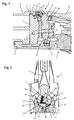
- FIG. 1 is a part of a hand gun designed here as Kipplaufgewehr with a tiltable on a system box or closure housing 1 arranged hook piece 2, a sliding on the closure housing 1 between a lower open position and an upper closed position closure block 3 and a rotatably mounted in the closure housing 1 locking lever 4 in longitudinal section ,
- the hook piece 2 receiving the rear ends of the barrels has on its rear side an upper hook-shaped extension 5 with an inner locking groove 6 for receiving an upper locking part 7 of the L-shaped closure block 3 in a side view.
- the closure lever 4 comprises a closure lever shaft 8 rotatably mounted in the closure housing 1 perpendicular to the longitudinal axis of the closure housing 1 and an operating handle 9 attached to the upper end of the closure lever shaft 8.
- the actuating device 10 for raising and lowering the closure block 3 contains two fork-shaped actuating elements 11 and 12 which are parallel to one another and displaceable transversely to the longitudinal axis of the closure lever shaft 8 and which are adjustable in opposite directions by rotation of the closure lever shaft 8 via a two-armed control lever 13.
- the adjusting block 3 is raised by moving the two actuating elements 11 and 12 together and lowered by moving apart of the two actuating elements 11 and 12.
- a traction element 14 which is displaceable transversely to the longitudinal axis of the closure lever shaft 8 is arranged in the upper region of the closure lever shaft 8, which contains a front engagement part 15 which engages in positive engagement with the closure block 3 and a rear control part 16 cooperating with the closure lever shaft 8.
- the formed in the form of a hook engaging member 15 is formed for engagement with an engaging part 17 on the upper side of the closure block 3.
- the control part 16 includes a passage opening with a cam 18, which is provided with an in FIG. 1 recognizable eccentric surface 19 in the upper region of the closure lever shaft 8 cooperates so that the tension member 14 is displaced by rotation of the closure lever shaft 8 in the longitudinal direction of the system or closure box 1 and transverse direction of displacement of the closure block 3.
- the eccentric surface 19 on the closure lever shaft 8 and the control curve 18 on the tension element 14 are adjusted such that the closure block 3 is only pulled against the closure housing 1 when the closure block 3 is placed on its underside by the two oppositely movable actuating elements 11 and 12.
- FIG. 1 partially shown handgun also has a in the FIGS. 2 to 4 in different positions shown locking mechanism for releasable mounting of the locking lever 4 in a desired locking position.
- the locking mechanism includes a locking lever 4 on the locking lever 4 transversely to the axis of rotation of the lock lever shaft 8 pivotally mounted locking lever 22 which has a detent 23 for latching engagement with a fixedly arranged on the closure housing 1 mating latch 24.
- the locking lever 22 is pivotable in the embodiment shown in a recess 20 of the locking lever 4 about an axis of rotation of the locking lever shaft 8 parallel axis of rotation 21.
- the detent 23 on the locking lever 22 is in the illustrated embodiment as a locking edge and the corresponding counter-latching 24 formed as a locking groove.
- the counter-latching 24 belonging to the latch 23 on the latching lever 22 is arranged in the embodiment shown on a separate latching element 25 which is fastened to the latching housing 1.
- the latching element 25 is designed in the manner of a half-shell-shaped insert and inserted into the closure housing 1.
- the closure housing 1 can be made, for example, of aluminum, while the detent element 25 can be produced with the counter-detent 24 made of steel or another high-strength material.
- the counter-latching 24 could, however, also be arranged directly on the closure housing 1.
- the formed here as a pin rotation axis 21 of the locking lever 22 is parallel and laterally offset from the axis of rotation of the lock lever shaft 8 in a placed on the upper end of the lock lever shaft 8 and secured by a transverse pin 26 against rotation front part 27 of the operating handle 9.
- a transverse bore 28 in the front part 27 of the actuating handle 9 a compression spring 29 is arranged, through which the free front end of the locking lever 22 is pressed with the catch 23 radially outward in the direction of the counter-latch 24.
- the unlocking pin 30 is arranged to be in the in FIG. 1 shown locked open position of the locking lever 4 with respect to a front end face 31 of the closure housing 1 protrudes.
- the longitudinal axis of the unlocking pin 30 extends perpendicular to the axis of rotation of the locking lever shaft 8 and is offset laterally relative to the axis of rotation 21 of the locking lever.
- the detent formed as a latching edge 23 engages the pressed by the compression spring 29 to the outside free end of the locking lever 22 in the predetermined detent position in the counter-latching 24 on the locking element 25 a.
- the shutter lever 4 in the in FIG. 3 shown locking position and the closure block 3 is held in a lower open position.
- the handgun can be closed after tilting the runs again, without the hook piece 2 runs on the closure block 3 when re-closing the weapon.
- the shutter lever 4, for example, for removing the shutter block 3 can also be rotated to a position pivoted beyond the detent position, without thereby the detent function is impaired.
Landscapes
- Engineering & Computer Science (AREA)
- General Engineering & Computer Science (AREA)
- Closures For Containers (AREA)
- Operating, Guiding And Securing Of Roll- Type Closing Members (AREA)
- Lock And Its Accessories (AREA)
Description
- Die Erfindung betrifft eine Handfeuerwaffe mit einem in einem Verschlussgehäuse drehbar gelagerten Verschlusshebel nach dem Oberbegriff des Anspruchs 1.
- Besonders bei Kipplaufgewehren wird die Betätigung des Verschlusses zur Verriegelung oder Entriegelung in der Regel über einen im Systemkasten bzw. im Verschlussgehäuse drehbar gelagerten Verschlusshebel bewirkt. Bei der Öffnung des Verschlusses und Abkippen der Läufe muss allerdings sichergestellt werden, dass der Verschlussblock oder der Verriegelungsmechanismus nicht selbsttätig in die Verriegelungsstellung gelangt, da das Hakenstück bzw. das Laufteil ansonsten beim erneuten Schließen auf den Verschlussmechanismus aufläuft und die Waffe sich somit nicht mehr schließen lässt.
- Bei einem aus der
DE 10 2007 044 993 B3 bekannten Kipplaufgewehr ist im Systemkasten ein federbelasteter Sperrstift angeordnet, der in eine entsprechende Nut des Verschlussblocks einrastet und dadurch den Verschlussblock beim Öffnen des Verschlusses in einer unteren Entriegelungsstellung hält. - Es sind auch bereits Verriegelungsmechanismen bekannt, bei denen der die Verriegelung betätigende Verschlusshebel beim Öffnen in einer vorgegeben Stellung gehalten wird, um zu verhindern, dass der Verriegelungsmechanismus noch vor dem Schließen der Waffe selbsttätig in die Verriegelungsstellung gelangt. Diese bekannten Verriegelungsmechanismen weisen in der Regel einen Sperrstift auf, der mit einer entsprechenden Bohrung oder einem federbelasteten Gegenstück im Systemkasten zusammenwirkt. Allerdings ist bei diesen Systemen die Verriegelungsposition festgelegt und kann nicht ohne weiteres verändert werden.
- Aufgabe der Erfindung ist es, eine Handfeuerwaffe der eingangs genannten Art zu schaffen, die eine einfache Veränderung der Raststellung des Verschlusshebels ermöglicht.
- Diese Aufgabe wird durch eine Handfeuerwaffe mit den Merkmalen des Anspruchs 1 gelöst.
- Die erfindungsgemäße Handfeuerwaffe weist einen Verriegelungsmechanismus zur lösbaren Halterung des Verschlusshebels in einer Raststellung auf, wobei der Verriegelungsmechanismus einen am Verschlusshebel oder am Verschlussgehäuse quer zur Drehachse der Verschlusshebelwelle schwenkbar gelagerten Rasthebel mit einer Rast und eine am Verschlussgehäuse bzw. am Verschlusshebel angeordnete Gegenrast zum Eingriff der Rast aufweist. Durch die Ausgestaltung des Rastelements als quer zur Drehachse der Verschlusshebelwelle schwenkbarer Rasthebel kann die Lage der Rastkante und damit die Raststellung des Verschlusshebels durch geringfügige Anpassung der Form des Rasthebels schnell und einfach verändert werden, ohne dass dadurch die Funktionsweise des Verriegelungsmechanismus verändert oder beeinträchtigt wird. Die Raststellung des Verschlusshebels kann so z.B. durch einfaches Abfeilen des Rasthebels auch ohne wesentliche Eingriffe und Beeinträchtigung der Funktionsweise angepasst bzw. verändert werden.
- Zweckmäßige Weiterbildungen und vorteilhafte Ausführungsformen der Erfindung sind Gegenstand der Unteransprüche.
- In einer konstruktiv besonders günstigen Ausführung sind der Rasthebel mit der Rast an dem Verschlusshebel und die zur Rast gehörende Gegenrast an dem Verschlussgehäuse angeordnet. Der Rasthebel könnte aber in entsprechender Weise auch an dem Verschlusskasten und die Gegenrast an dem Verschlusshebel angeordnet sein.
- In vorteilhafter Weise kann z.B. der Rasthebel um eine zur Drehachse der Verschlusshebelwelle parallele Drehachse schwenkbar sein.
- Das freie vordere Ende des Rasthebels mit der daran vorgesehenen Rast kann in einer weiteren zweckmäßigen Ausgestaltung durch eine Druckfeder in Richtung der Gegenrast gedrückt und durch einen Entriegelungsstift außer Eingriff mit der Gegenrast gebracht werden. Die Rast kann zweckmäßigerweise als Rastkante und die dazugehörige Gegenrast als Rastnut ausgebildet sein.
- In einer weiteren zweckmäßigen Ausgestaltung können der Rasthebel in einer Aussparung des Verschlusshebels und die Gegenrast an einem Rastelement am Verschlussgehäuse angeordnet sein. Das Rastelement mit der daran befindlichen Gegenrast kann so aus einem stabilen und festen Material hergestellt sein, während der Verschlusskasten z.B. aus Aluminium oder einem anderen leichten Material gefertigt sein kann.
- Weitere Besonderheiten und Vorzüge der Erfindung ergeben sich aus der folgenden Beschreibung eines bevorzugten Ausführungsbeispiels anhand der Zeichnung. Es zeigen:
- Figur 1
- einen Längsschnitt durch einen Teil einer Handfeuerwaffe mit einem Verschlussgehäuse und einem im Verschlussgehäuse drehbar gelagerten Verschlusshebel;
- Figur 2
- einen Querschnitt durch das Verschlussgehäuse und den Verschlusshebel in einer Schließstellung;
- Figur 3
- einen Querschnitt durch das Verschlussgehäuse und den Verschlusshebel in einer verrasteten Öffnungsstellung und
- Figur 4
- einen Querschnitt durch das Verschlussgehäuse und den Verschlusshebel in einer über die verrastete Öffnungsstellung hinaus verschwenkten Stellung.
- In
Figur 1 ist ein Teil einer hier als Kipplaufgewehr ausgebildeten Handfeuerwaffe mit einer an einem Systemkasten bzw. Verschlussgehäuse 1 kippbar angeordneten Hakenstück 2, einem am Verschlussgehäuse 1 zwischen einer unteren Öffnungsstellung und einer oberen Schließstellung verschiebbaren Verschlussblock 3 und einem im Verschlussgehäuse 1 drehbar gelagerten Verschlusshebel 4 im Längschnitt gezeigt. Das die hinteren Enden der Läufe aufnehmende Hakenstück 2 weist an seiner Rückseite eine obere hakenförmige Verlängerung 5 mit einer inneren Verriegelungsnut 6 zur Aufnahme eines oberen Verriegelungsteils 7 des in einer Seitenansicht L-förmigen Verschlussblocks 3 auf. - Der Verschlusshebel 4 umfasst eine im Verschlussgehäuse 1 senkrecht zur Längsachse des Verschlussgehäuses 1 drehbar gelagerte Verschlusshebelwelle 8 und einem am oberen Ende der Verschlusshebelwelle 8 befestigten Betätigungsgriff 9. Durch Drehung der Verschlusshebelwelle 8 mit Hilfe des Betätigungsgriffs 9 ist der parallel zur Längsachse der Verschlusshebelwelle 8 verschiebbare Verschlussblock 3 über eine Betätigungseinrichtung 10 zwischen einer unteren Öffnungsstellung und der in
Figur 1 gezeigten oberen Schließstellung bewegbar. Die Betätigungseinrichtung 10 zum Anheben und Ansenken des Verschlussblocks 3 enthält zwei zueinander parallele und quer zur Längsachse der Verschlusshebelwelle 8 verschiebbare, gabelförmige Betätigungselemente 11 und 12, die durch Drehung der Verschlusshebelwelle 8 über einen zweiarmigen Steuerhebel 13 entgegengesetzt zueinander verstellbar sind. Der Verstellblock 3 wird durch Zusammenfahren der beiden Betätigungselemente 11 und 12 angehoben und durch Auseinanderfahren der beiden Betätigungselemente 11 und 12 abgesenkt. - In dem Verschlussgehäuse 1 ist im oberen Bereich der Verschlusshebelwelle 8 ein quer zur Längsachse der Verschlusshebelwelle 8 verschiebbares Zugelement 14 angeordnet, das ein in formschlüssigen Eingriff mit dem Verschlussblock 3 gelangendes vorderes Eingriffsteil 15 und ein mit der Verschlusshebelwelle 8 zusammenwirkendes hinteres Steuerteil 16 enthält. Das in Form eines Hakens ausgebildete Eingriffsteil 15 ist zum Eingriff mit einem Angriffsteil 17 an der Oberseite des Verschlussblocks 3 ausgebildet. Das Steuerteil 16 enthält eine Durchgangsöffnung mit einer Steuerkurve 18, die mit einer in
Figur 1 erkennbaren Exzenterfläche 19 im oberen Bereich der Verschlusshebelwelle 8 so zusammenwirkt, dass das Zugelement 14 durch eine Drehung des Verschlusshebelwelle 8 in Längsrichtung des System- bzw. Verschlusskastens 1 bzw. quer Verschieberichtung des Verschlussblocks 3 verschoben wird. Die Exzenterfläche 19 an der Verschlusshebelwelle 8 und die Steuerkurve 18 am Zugelement 14 sind so abgestimmt, dass der Verschlussblock 3 erst dann gegen das Verschlussgehäuse 1 gezogen wird, wenn der Verschlussblock 3 an seiner Unterseite von den beiden entgegengesetzt beweglichen Betätigungselementen 11 und 12 unterstellt ist. - Die in
Figur 1 zum Teil dargestellte Handfeuerwaffe weist ferner einen in denFiguren 2 bis 4 in unterschiedlichen Stellungen gezeigten Verriegelungsmechanismus zur lösbaren Halterung des Verschlusshebels 4 in einer gewünschten Raststellung auf. - Wie aus
Figur 2 hervorgeht, enthält der Verriegelungsmechanismus einen am Verschlusshebel 4 quer zur Drehachse der Verschlusshebelwelle 8 schwenkbar gelagerten Rasthebel 22, der eine Rast 23 zum verrastenden Eingriff mit einer fest am Verschlussgehäuse 1 angeordneten Gegenrast 24 aufweist. Der Rasthebel 22 ist bei der gezeigten Ausführung in einer Ausnehmung 20 des Verschlusshebels 4 um eine zur Drehachse der Verschlusshebelwelle 8 parallele Drehachse 21 schwenkbar. Die Rast 23 an dem Rasthebel 22 ist bei dem dargestellten Ausführungsbeispiel als Rastkante und die entsprechende Gegenrast 24 als Rastnut ausgebildet. Die zur Rast 23 am Rasthebel 22 gehörende Gegenrast 24 ist bei der gezeigten Ausführung an einem gesonderten Rastelement 25 angeordnet, das am Verschlussgehäuse 1 befestigt ist. Das Rastelement 25 ist in Art eines halbschalenförmigen Einsatzes ausgebildet und in das Verschlussgehäuse 1 eingesetzt. Dadurch kann das Verschlussgehäuse 1 z.B. aus Aluminium gefertigt werden, während das Rastelement 25 mit der Gegenrast 24 aus Stahl oder einem anderen hochfesten Material hergestellt werden kann. Bei ausreichender Stabilität des Verschlussgehäuses 1 könnte die Gegenrast 24 aber auch unmittelbar an dem Verschlussgehäuse 1 angeordnet sein. - Die hier als Stift ausgebildete Drehachse 21 des Rasthebels 22 ist parallel und seitlich versetzt zur Drehachse der Verschlusshebelwelle 8 in einem auf das obere Ende der Verschlusshebelwelle 8 aufgesetzten und durch einem Querstift 26 gegen Verdrehung gesicherten vorderen Teil 27 des Betätigungsgriffs 9 angeordnet. In dem vorderen Teil 27 des Betätigungsgriffs 9 ist auch die Ausnehmung 20 für den Rasthebel 22 vorgesehen. Ferner ist in einer Querbohrung 28 in dem vorderen Teil 27 des Betätigungsgriffs 9 eine Druckfeder 29 angeordnet, durch die das freie vordere Ende des Rasthebels 22 mit der Rast 23 radial nach außen in Richtung der Gegenrast 24 gedrückt wird. Durch einen im Verschlussgehäuse 1 angeordneten Entriegelungsstift 30 kann das freie vordere Ende des Rasthebels 22 mit der Rast 23 entgegen der Kraft der Druckfeder 29 nach innen und aus der Verrastung herausgedrückt werden. Der Entriegelungsstift 30 ist derart angeordnet, dass er in der in
Figur 1 gezeigten verriegelten Öffnungsstellung des Verschlusshebels 4 gegenüber einer vorderen Stirnfläche 31 des Verschlussgehäuses 1 vorsteht. Die Längsachse des Entriegelungsstifts 30 verläuft senkrecht zur Drehachse der Verschlusshebelwelle 8 und ist gegenüber der Drehachse 21 des Rasthebels seitlich versetzt. - Wird der Verschlusshebel 4 aus seiner in
Figur 2 dargestellten Schließstellung gemäßFigur 3 in eine Öffnungsrichtung verschwenkt, rastet die als Rastkante ausgebildete Rast 23 an dem durch die Druckfeder 29 nach außen gedrückten freien Ende des Rasthebels 22 in der vorgegebenen Raststellung in die Gegenrast 24 am Rastelement 25 ein. Dadurch werden der Verschlusshebel 4 in der inFigur 3 gezeigten Raststellung und der Verschlussblock 3 in einer unteren Öffnungsstellung gehalten. Somit kann die Handfeuerwaffe nach dem Abkippen der Läufe wieder geschlossen werden, ohne dass das Hakenstück 2 beim erneuten Verschließen der Waffe auf den Verschlussblock 3 aufläuft. - Erst wenn das Hakenstück 2 wieder in die in
Figur 1 gezeigte Schließstellung gelangt, wird der Rasthebel 22 von dem Entriegelungsstift 30 entgegen der Kraft der Druckfeder 29 nach innen gedrückt, so dass die Rast 23 außer Eingriff mit der Gegenrast 24 gelangt und sich dadurch der Verschlusshebel 4 wieder in die inFigur 2 gezeigte Schließstellung bewegen kann. - Wie aus
Figur 4 ersichtlich ist, kann der Verschlusshebel 4 z.B. zur Entnahme des Verschlussblocks 3 auch in eine über die Raststellung hinaus verschwenkte Stellung gedreht werden, ohne dass dadurch die Rastfunktion beeinträchtigt wird.
Claims (11)
- Handfeuerwaffe mit einem Verschlussgehäuse (1), einem Verschlusshebel (4) mit einer im Verschlussgehäuse (1) drehbar gelagerten Verschlusshebelwelle (8) und einem Verriegelungsmechanismus (22, 23, 24) zur lösbaren Halterung des Verschlusshebels (4) in einer Raststellung, dadurch gekennzeichnet, dass der Verriegelungsmechanismus (22, 23, 24) einen am Verschlusshebel (4) oder am Verschlussgehäuse (1) quer zur Drehachse der Verschlusshebelwelle (8) schwenkbar gelagerten Rasthebel (22) mit einer Rast (23) und eine zur Rast gehörende Gegenrast (24) zum Eingriff der Rast (23) enthält.
- Handfeuerwaffe nach Anspruch 1, dadurch gekennzeichnet, dass der Rasthebel (22) mit der Rast (23) an dem Verschlusshebel (4) und die Gegenrast (24) an dem Verschlussgehäuse (1) oder der Rasthebel (22) mit der Rast (23) an dem Verschlussgehäuse (1) und die Gegenrast (24) an dem Verschlusshebel (4) angeordnet sind.
- Handfeuerwaffe nach Anspruch 1 oder 2, dadurch gekennzeichnet, dass der Rasthebel (22) um eine zur Drehachse der Verschlusshebelwelle (8) parallele Drehachse (21) schwenkbar ist.
- Handfeuerwaffe nach einem der Ansprüche 1 bis 3, dadurch gekennzeichnet, dass das freie vordere Ende des Rasthebels (22) mit der Rast (23) durch eine Druckfeder (29) in Richtung der Gegenrast (24) gedrückt wird.
- Handfeuerwaffe nach einem der Ansprüche 1 bis 4, dadurch gekennzeichnet, dass die Rast (23) am Rasthebel (22) durch einen Entriegelungsstift (30) außer Eingriff mit der Gegenrast (24) bringbar ist.
- Handfeuerwaffe nach einem der Ansprüche 1 bis 5, dadurch gekennzeichnet, dass die Rast (23) am Rasthebel (22) als Rastkante und die zur Rast (23) gehörende Gegenrast (24) als Rastnut ausgebildet ist.
- Handfeuerwaffe nach einem der Ansprüche 1 bis 6, dadurch gekennzeichnet, dass der Rasthebel (23) in einer Aussparung (20) des Verschlusshebels (4) und die Gegenrast (24) an einem Rastelement (25) am Verschlussgehäuse (1) angeordnet ist.
- Handfeuerwaffe nach Anspruch 7, dadurch gekennzeichnet, dass die Aussparung (20) für den Rasthebel (23) in einem auf das obere Ende der Verschlusshebelwelle (8) aufgesetzten und durch einem Querstift (26) gegen Verdrehung gesicherten vorderen Teil (27) eines Betätigungsgriffs (9) des Verschlusshebel (4) angeordnet ist.
- Handfeuerwaffe nach einem der Ansprüche 1 bis 8, dadurch gekennzeichnet, dass durch die Verschlusshebelwelle (8) ein Verschlussblock (3) über eine Betätigungseinrichtung (10) zwischen einer unteren Öffnungsstellung und einer oberen Schließstellung verschiebbar ist.
- Handfeuerwaffe nach Anspruch 9, dadurch gekennzeichnet, dass die Betätigungseinrichtung (10) zwei gegeneinander verschiebbare Betätigungselemente (11, 12) enthält.
- Handfeuerwaffe nach Anspruch 9 oder 10, dadurch gekennzeichnet, dass durch die Verschlusshebelwelle (8) ein am Verschlussblock (3) angreifendes Zugelement (14) mit einem in formschlüssigen Eingriff mit dem Verschlussblock (3) gelangenden vorderen Eingriffsteil (15) und einem mit der Verschlusshebelwelle (8) zusammenwirkenden hinteren Steuerteil (16) verschiebbar ist.
Applications Claiming Priority (1)
| Application Number | Priority Date | Filing Date | Title |
|---|---|---|---|
| DE201410102657 DE102014102657B3 (de) | 2014-02-28 | 2014-02-28 | Handfeuerwaffe mit Verschlusshebel |
Publications (2)
| Publication Number | Publication Date |
|---|---|
| EP2913620A1 EP2913620A1 (de) | 2015-09-02 |
| EP2913620B1 true EP2913620B1 (de) | 2016-03-23 |
Family
ID=52477655
Family Applications (1)
| Application Number | Title | Priority Date | Filing Date |
|---|---|---|---|
| EP15155524.0A Active EP2913620B1 (de) | 2014-02-28 | 2015-02-18 | Handfeuerwaffe mit Verschlusshebel |
Country Status (3)
| Country | Link |
|---|---|
| EP (1) | EP2913620B1 (de) |
| DE (1) | DE102014102657B3 (de) |
| RU (1) | RU2606247C2 (de) |
Family Cites Families (5)
| Publication number | Priority date | Publication date | Assignee | Title |
|---|---|---|---|---|
| FR2312753A1 (fr) * | 1975-05-28 | 1976-12-24 | Chapuis Paul | Perfectionnements apportes aux fusils de chasse ou autres armes a canons juxtaposes |
| US5459956A (en) * | 1993-12-30 | 1995-10-24 | Remington Arms Company, Inc. | Firearm ejector system |
| DE19909580B4 (de) * | 1999-03-04 | 2007-04-12 | Suhler Jagd- Und Sportwaffen Gmbh | Kipplaufwaffe mit herausnehmbarem Blockverschluß |
| DE10118046A1 (de) * | 2001-04-11 | 2002-10-24 | Blaser Horst Jagdwaffen | Schloßsystem für mehrläufige Gewehre |
| DE102007044993B3 (de) * | 2007-09-20 | 2009-01-08 | Blaser Finanzholding Gmbh | Kipplaufgewehr mit Blockverschluss |
-
2014
- 2014-02-28 DE DE201410102657 patent/DE102014102657B3/de not_active Expired - Fee Related
-
2015
- 2015-02-18 EP EP15155524.0A patent/EP2913620B1/de active Active
- 2015-02-26 RU RU2015106424A patent/RU2606247C2/ru active
Also Published As
| Publication number | Publication date |
|---|---|
| RU2015106424A (ru) | 2016-09-20 |
| RU2606247C2 (ru) | 2017-01-10 |
| EP2913620A1 (de) | 2015-09-02 |
| DE102014102657B3 (de) | 2015-04-30 |
Similar Documents
| Publication | Publication Date | Title |
|---|---|---|
| AT501774A1 (de) | Holster für handfeuerwaffen | |
| DE102012014075A1 (de) | Vorrichtung zur Montage einer Zieleinrichtung an einer Handfeuerwaffe | |
| DE102016120891A1 (de) | Verschluss für Schusswaffen | |
| DE1553916B2 (de) | Gewehr mit Fallblockverschluss | |
| DE102007044993B3 (de) | Kipplaufgewehr mit Blockverschluss | |
| EP3411547B1 (de) | Vorreiberverschluss mit einem in unterschiedlicher höhe an einer schliesswelle fixierbaren verschlusselement | |
| DE1653994B2 (de) | Kraftfahrzeugtürverschluß | |
| DE717308C (de) | Fallenschloss fuer Kraftwagentueren | |
| EP2774869A1 (de) | Behälterverschluss | |
| EP3183408B1 (de) | Steuerelement für eine beschlaganordnung | |
| DE102014102657B3 (de) | Handfeuerwaffe mit Verschlusshebel | |
| DE102015100945A1 (de) | Handgriffvorrichtung | |
| EP4045744B1 (de) | Beschlaganordnung | |
| DE202014100915U1 (de) | Handfeuerwaffe mit Verschlusshebel | |
| AT13131U1 (de) | Verschluss für eine Schusswaffe | |
| EP3205970B1 (de) | Kipplaufwaffe | |
| EP3287571B1 (de) | Campingfahrzeug mit einer markise sowie markise | |
| DE102005015515A1 (de) | Drehfallenverschluss | |
| EP2602413B1 (de) | Verriegelungseinrichtung zum Arretieren eines Fensterladens oder Türladens | |
| DE102014000724B4 (de) | Hubbett für Land-, Wasser- und Luftfahrzeuge mit Betätigungseinrichtung | |
| DE102014112072B4 (de) | Flügelheber | |
| EP2913621B1 (de) | Kipplaufgewehr mit Blockverschluss | |
| DE102007007519A1 (de) | Schließautomat für einen Tür- oder Fensterflügel | |
| DE102008004452B3 (de) | Verstellbarer Schraubenschlüssel | |
| EP2944746B1 (de) | Verschluss |
Legal Events
| Date | Code | Title | Description |
|---|---|---|---|
| PUAI | Public reference made under article 153(3) epc to a published international application that has entered the european phase |
Free format text: ORIGINAL CODE: 0009012 |
|
| 17P | Request for examination filed |
Effective date: 20150713 |
|
| AK | Designated contracting states |
Kind code of ref document: A1 Designated state(s): AL AT BE BG CH CY CZ DE DK EE ES FI FR GB GR HR HU IE IS IT LI LT LU LV MC MK MT NL NO PL PT RO RS SE SI SK SM TR |
|
| AX | Request for extension of the european patent |
Extension state: BA ME |
|
| GRAP | Despatch of communication of intention to grant a patent |
Free format text: ORIGINAL CODE: EPIDOSNIGR1 |
|
| RIC1 | Information provided on ipc code assigned before grant |
Ipc: F41A 3/58 20060101AFI20150928BHEP |
|
| INTG | Intention to grant announced |
Effective date: 20151026 |
|
| GRAS | Grant fee paid |
Free format text: ORIGINAL CODE: EPIDOSNIGR3 |
|
| GRAA | (expected) grant |
Free format text: ORIGINAL CODE: 0009210 |
|
| AK | Designated contracting states |
Kind code of ref document: B1 Designated state(s): AL AT BE BG CH CY CZ DE DK EE ES FI FR GB GR HR HU IE IS IT LI LT LU LV MC MK MT NL NO PL PT RO RS SE SI SK SM TR |
|
| REG | Reference to a national code |
Ref country code: GB Ref legal event code: FG4D Free format text: NOT ENGLISH |
|
| REG | Reference to a national code |
Ref country code: CH Ref legal event code: EP |
|
| REG | Reference to a national code |
Ref country code: AT Ref legal event code: REF Ref document number: 783578 Country of ref document: AT Kind code of ref document: T Effective date: 20160415 Ref country code: CH Ref legal event code: NV Representative=s name: LUCHS AND PARTNER AG PATENTANWAELTE, CH |
|
| REG | Reference to a national code |
Ref country code: IE Ref legal event code: FG4D Free format text: LANGUAGE OF EP DOCUMENT: GERMAN |
|
| REG | Reference to a national code |
Ref country code: DE Ref legal event code: R096 Ref document number: 502015000008 Country of ref document: DE |
|
| REG | Reference to a national code |
Ref country code: LT Ref legal event code: MG4D |
|
| REG | Reference to a national code |
Ref country code: NL Ref legal event code: MP Effective date: 20160323 |
|
| PG25 | Lapsed in a contracting state [announced via postgrant information from national office to epo] |
Ref country code: FI Free format text: LAPSE BECAUSE OF FAILURE TO SUBMIT A TRANSLATION OF THE DESCRIPTION OR TO PAY THE FEE WITHIN THE PRESCRIBED TIME-LIMIT Effective date: 20160323 Ref country code: GR Free format text: LAPSE BECAUSE OF FAILURE TO SUBMIT A TRANSLATION OF THE DESCRIPTION OR TO PAY THE FEE WITHIN THE PRESCRIBED TIME-LIMIT Effective date: 20160624 Ref country code: HR Free format text: LAPSE BECAUSE OF FAILURE TO SUBMIT A TRANSLATION OF THE DESCRIPTION OR TO PAY THE FEE WITHIN THE PRESCRIBED TIME-LIMIT Effective date: 20160323 Ref country code: NO Free format text: LAPSE BECAUSE OF FAILURE TO SUBMIT A TRANSLATION OF THE DESCRIPTION OR TO PAY THE FEE WITHIN THE PRESCRIBED TIME-LIMIT Effective date: 20160623 |
|
| PG25 | Lapsed in a contracting state [announced via postgrant information from national office to epo] |
Ref country code: LV Free format text: LAPSE BECAUSE OF FAILURE TO SUBMIT A TRANSLATION OF THE DESCRIPTION OR TO PAY THE FEE WITHIN THE PRESCRIBED TIME-LIMIT Effective date: 20160323 Ref country code: RS Free format text: LAPSE BECAUSE OF FAILURE TO SUBMIT A TRANSLATION OF THE DESCRIPTION OR TO PAY THE FEE WITHIN THE PRESCRIBED TIME-LIMIT Effective date: 20160323 Ref country code: SE Free format text: LAPSE BECAUSE OF FAILURE TO SUBMIT A TRANSLATION OF THE DESCRIPTION OR TO PAY THE FEE WITHIN THE PRESCRIBED TIME-LIMIT Effective date: 20160323 Ref country code: NL Free format text: LAPSE BECAUSE OF FAILURE TO SUBMIT A TRANSLATION OF THE DESCRIPTION OR TO PAY THE FEE WITHIN THE PRESCRIBED TIME-LIMIT Effective date: 20160323 Ref country code: LT Free format text: LAPSE BECAUSE OF FAILURE TO SUBMIT A TRANSLATION OF THE DESCRIPTION OR TO PAY THE FEE WITHIN THE PRESCRIBED TIME-LIMIT Effective date: 20160323 |
|
| PG25 | Lapsed in a contracting state [announced via postgrant information from national office to epo] |
Ref country code: PL Free format text: LAPSE BECAUSE OF FAILURE TO SUBMIT A TRANSLATION OF THE DESCRIPTION OR TO PAY THE FEE WITHIN THE PRESCRIBED TIME-LIMIT Effective date: 20160323 Ref country code: EE Free format text: LAPSE BECAUSE OF FAILURE TO SUBMIT A TRANSLATION OF THE DESCRIPTION OR TO PAY THE FEE WITHIN THE PRESCRIBED TIME-LIMIT Effective date: 20160323 Ref country code: IS Free format text: LAPSE BECAUSE OF FAILURE TO SUBMIT A TRANSLATION OF THE DESCRIPTION OR TO PAY THE FEE WITHIN THE PRESCRIBED TIME-LIMIT Effective date: 20160723 |
|
| PG25 | Lapsed in a contracting state [announced via postgrant information from national office to epo] |
Ref country code: CZ Free format text: LAPSE BECAUSE OF FAILURE TO SUBMIT A TRANSLATION OF THE DESCRIPTION OR TO PAY THE FEE WITHIN THE PRESCRIBED TIME-LIMIT Effective date: 20160323 Ref country code: PT Free format text: LAPSE BECAUSE OF FAILURE TO SUBMIT A TRANSLATION OF THE DESCRIPTION OR TO PAY THE FEE WITHIN THE PRESCRIBED TIME-LIMIT Effective date: 20160725 Ref country code: SM Free format text: LAPSE BECAUSE OF FAILURE TO SUBMIT A TRANSLATION OF THE DESCRIPTION OR TO PAY THE FEE WITHIN THE PRESCRIBED TIME-LIMIT Effective date: 20160323 Ref country code: SK Free format text: LAPSE BECAUSE OF FAILURE TO SUBMIT A TRANSLATION OF THE DESCRIPTION OR TO PAY THE FEE WITHIN THE PRESCRIBED TIME-LIMIT Effective date: 20160323 Ref country code: RO Free format text: LAPSE BECAUSE OF FAILURE TO SUBMIT A TRANSLATION OF THE DESCRIPTION OR TO PAY THE FEE WITHIN THE PRESCRIBED TIME-LIMIT Effective date: 20160323 Ref country code: ES Free format text: LAPSE BECAUSE OF FAILURE TO SUBMIT A TRANSLATION OF THE DESCRIPTION OR TO PAY THE FEE WITHIN THE PRESCRIBED TIME-LIMIT Effective date: 20160323 |
|
| PG25 | Lapsed in a contracting state [announced via postgrant information from national office to epo] |
Ref country code: IT Free format text: LAPSE BECAUSE OF FAILURE TO SUBMIT A TRANSLATION OF THE DESCRIPTION OR TO PAY THE FEE WITHIN THE PRESCRIBED TIME-LIMIT Effective date: 20160323 |
|
| REG | Reference to a national code |
Ref country code: DE Ref legal event code: R097 Ref document number: 502015000008 Country of ref document: DE |
|
| PLBE | No opposition filed within time limit |
Free format text: ORIGINAL CODE: 0009261 |
|
| STAA | Information on the status of an ep patent application or granted ep patent |
Free format text: STATUS: NO OPPOSITION FILED WITHIN TIME LIMIT |
|
| PG25 | Lapsed in a contracting state [announced via postgrant information from national office to epo] |
Ref country code: DK Free format text: LAPSE BECAUSE OF FAILURE TO SUBMIT A TRANSLATION OF THE DESCRIPTION OR TO PAY THE FEE WITHIN THE PRESCRIBED TIME-LIMIT Effective date: 20160323 |
|
| REG | Reference to a national code |
Ref country code: FR Ref legal event code: PLFP Year of fee payment: 3 |
|
| PG25 | Lapsed in a contracting state [announced via postgrant information from national office to epo] |
Ref country code: BG Free format text: LAPSE BECAUSE OF FAILURE TO SUBMIT A TRANSLATION OF THE DESCRIPTION OR TO PAY THE FEE WITHIN THE PRESCRIBED TIME-LIMIT Effective date: 20160623 |
|
| 26N | No opposition filed |
Effective date: 20170102 |
|
| PG25 | Lapsed in a contracting state [announced via postgrant information from national office to epo] |
Ref country code: BE Free format text: LAPSE BECAUSE OF NON-PAYMENT OF DUE FEES Effective date: 20170228 Ref country code: SI Free format text: LAPSE BECAUSE OF FAILURE TO SUBMIT A TRANSLATION OF THE DESCRIPTION OR TO PAY THE FEE WITHIN THE PRESCRIBED TIME-LIMIT Effective date: 20160323 |
|
| PG25 | Lapsed in a contracting state [announced via postgrant information from national office to epo] |
Ref country code: MC Free format text: LAPSE BECAUSE OF FAILURE TO SUBMIT A TRANSLATION OF THE DESCRIPTION OR TO PAY THE FEE WITHIN THE PRESCRIBED TIME-LIMIT Effective date: 20160323 |
|
| REG | Reference to a national code |
Ref country code: IE Ref legal event code: MM4A |
|
| REG | Reference to a national code |
Ref country code: FR Ref legal event code: PLFP Year of fee payment: 4 |
|
| PG25 | Lapsed in a contracting state [announced via postgrant information from national office to epo] |
Ref country code: LU Free format text: LAPSE BECAUSE OF NON-PAYMENT OF DUE FEES Effective date: 20170218 |
|
| REG | Reference to a national code |
Ref country code: BE Ref legal event code: MM Effective date: 20170228 |
|
| PG25 | Lapsed in a contracting state [announced via postgrant information from national office to epo] |
Ref country code: IE Free format text: LAPSE BECAUSE OF NON-PAYMENT OF DUE FEES Effective date: 20170218 |
|
| PG25 | Lapsed in a contracting state [announced via postgrant information from national office to epo] |
Ref country code: MT Free format text: LAPSE BECAUSE OF FAILURE TO SUBMIT A TRANSLATION OF THE DESCRIPTION OR TO PAY THE FEE WITHIN THE PRESCRIBED TIME-LIMIT Effective date: 20160323 |
|
| PG25 | Lapsed in a contracting state [announced via postgrant information from national office to epo] |
Ref country code: AL Free format text: LAPSE BECAUSE OF FAILURE TO SUBMIT A TRANSLATION OF THE DESCRIPTION OR TO PAY THE FEE WITHIN THE PRESCRIBED TIME-LIMIT Effective date: 20160323 |
|
| PG25 | Lapsed in a contracting state [announced via postgrant information from national office to epo] |
Ref country code: HU Free format text: LAPSE BECAUSE OF FAILURE TO SUBMIT A TRANSLATION OF THE DESCRIPTION OR TO PAY THE FEE WITHIN THE PRESCRIBED TIME-LIMIT; INVALID AB INITIO Effective date: 20150218 |
|
| GBPC | Gb: european patent ceased through non-payment of renewal fee |
Effective date: 20190218 |
|
| PG25 | Lapsed in a contracting state [announced via postgrant information from national office to epo] |
Ref country code: CY Free format text: LAPSE BECAUSE OF FAILURE TO SUBMIT A TRANSLATION OF THE DESCRIPTION OR TO PAY THE FEE WITHIN THE PRESCRIBED TIME-LIMIT Effective date: 20160323 |
|
| PG25 | Lapsed in a contracting state [announced via postgrant information from national office to epo] |
Ref country code: MK Free format text: LAPSE BECAUSE OF FAILURE TO SUBMIT A TRANSLATION OF THE DESCRIPTION OR TO PAY THE FEE WITHIN THE PRESCRIBED TIME-LIMIT Effective date: 20160323 |
|
| PG25 | Lapsed in a contracting state [announced via postgrant information from national office to epo] |
Ref country code: GB Free format text: LAPSE BECAUSE OF NON-PAYMENT OF DUE FEES Effective date: 20190218 |
|
| PG25 | Lapsed in a contracting state [announced via postgrant information from national office to epo] |
Ref country code: TR Free format text: LAPSE BECAUSE OF FAILURE TO SUBMIT A TRANSLATION OF THE DESCRIPTION OR TO PAY THE FEE WITHIN THE PRESCRIBED TIME-LIMIT Effective date: 20160323 |
|
| REG | Reference to a national code |
Ref country code: DE Ref legal event code: R081 Ref document number: 502015000008 Country of ref document: DE Owner name: BLASER GROUP GMBH, DE Free format text: FORMER OWNER: L&O HUNTING GROUP GMBH, 88316 ISNY, DE |
|
| REG | Reference to a national code |
Ref country code: CH Ref legal event code: U11 Free format text: ST27 STATUS EVENT CODE: U-0-0-U10-U11 (AS PROVIDED BY THE NATIONAL OFFICE) Effective date: 20260301 |
|
| PGFP | Annual fee paid to national office [announced via postgrant information from national office to epo] |
Ref country code: DE Payment date: 20260306 Year of fee payment: 12 |
|
| PGFP | Annual fee paid to national office [announced via postgrant information from national office to epo] |
Ref country code: AT Payment date: 20260216 Year of fee payment: 12 |
|
| PGFP | Annual fee paid to national office [announced via postgrant information from national office to epo] |
Ref country code: FR Payment date: 20260223 Year of fee payment: 12 |
|
| PGFP | Annual fee paid to national office [announced via postgrant information from national office to epo] |
Ref country code: CH Payment date: 20260301 Year of fee payment: 12 |